JP2012062008A - Vehicle seat - Google Patents

Vehicle seat Download PDF

Info

Publication number
JP2012062008A
JP2012062008A JP2010209494A JP2010209494A JP2012062008A JP 2012062008 A JP2012062008 A JP 2012062008A JP 2010209494 A JP2010209494 A JP 2010209494A JP 2010209494 A JP2010209494 A JP 2010209494A JP 2012062008 A JP2012062008 A JP 2012062008A
Authority
JP
Japan
Prior art keywords
seat
transmission block
load transmission
width direction
frame
Prior art date
Legal status (The legal status is an assumption and is not a legal conclusion. Google has not performed a legal analysis and makes no representation as to the accuracy of the status listed.)
Granted
Application number
JP2010209494A
Other languages
Japanese (ja)
Other versions
JP5538155B2 (en
Inventor
Jogen Yamaki
状元 山木
Hiroyuki Kaku
裕之 郭
Current Assignee (The listed assignees may be inaccurate. Google has not performed a legal analysis and makes no representation or warranty as to the accuracy of the list.)
Honda Motor Co Ltd
TS Tech Co Ltd
Original Assignee
Honda Motor Co Ltd
TS Tech Co Ltd
Priority date (The priority date is an assumption and is not a legal conclusion. Google has not performed a legal analysis and makes no representation as to the accuracy of the date listed.)
Filing date
Publication date
Application filed by Honda Motor Co Ltd, TS Tech Co Ltd filed Critical Honda Motor Co Ltd
Priority to JP2010209494A priority Critical patent/JP5538155B2/en
Publication of JP2012062008A publication Critical patent/JP2012062008A/en
Application granted granted Critical
Publication of JP5538155B2 publication Critical patent/JP5538155B2/en
Expired - Fee Related legal-status Critical Current
Anticipated expiration legal-status Critical

Links

Images

Landscapes

  • Seats For Vehicles (AREA)

Abstract

【課題】荷重伝達ブロックの背部側でのシート表皮の皺の発生を抑制して、外観品質の向上を図ることのできる車両用シートを提供する。
【解決手段】シートバックフレームの車幅方向外側の側部フレーム部13cに荷重伝達ブロック18を設け、側部フレーム部13cと荷重伝達ブロック18の外側をシート表皮28によって覆う。荷重伝達ブロック18の背面側にシート表皮28の形状だしを行うカバー部材45を設ける。
【選択図】図11
An object of the present invention is to provide a vehicle seat capable of suppressing the occurrence of wrinkles on the seat skin on the back side of a load transmission block and improving the appearance quality.
A load transmission block 18 is provided on a side frame portion 13c outside the seat back frame in the vehicle width direction, and the outside of the side frame portion 13c and the load transmission block 18 is covered with a seat skin 28. A cover member 45 is provided on the back side of the load transmission block 18 to shape the seat skin 28.
[Selection] Figure 11

Description

この発明は、車両側方から入力される衝撃荷重を車体の幅方向内側領域に伝達する機能を備えた車両用シートに関するものである。   The present invention relates to a vehicle seat having a function of transmitting an impact load input from the side of a vehicle to an inner region in the width direction of the vehicle body.

衝突時等に車両側方から入力される衝撃荷重を、シートを介して車体の幅方向内側に伝達するものが知られている(例えば、特許文献1参照)。   A device that transmits an impact load input from the side of a vehicle at the time of a collision or the like to the inner side in the width direction of the vehicle body via a seat is known (for example, see Patent Document 1).

この車両用シートは、シートバックの外側骨格部をなすシートバックフレームが矩形枠状に形成され、シートバックフレームの車幅方向外側の側部フレーム部に、シート幅方向の外側に突出して、車体側部から入力された衝撃荷重をシートバックフレームに伝達する荷重伝達ブロックが取り付けられている。また、シートバックフレームにはパッド材が取り付けられており、荷重伝達ブロックは、シートバックフレームやパッド材とともに外面側がシート表皮によって覆われている。   In this vehicle seat, a seat back frame forming an outer skeleton portion of the seat back is formed in a rectangular frame shape, and protrudes outward in the seat width direction on a side frame portion on the outer side in the vehicle width direction of the seat back frame. A load transmission block for transmitting an impact load input from the side portion to the seat back frame is attached. A pad material is attached to the seat back frame, and the load transmission block is covered with a seat skin on the outer surface side together with the seat back frame and the pad material.

特開平8−156668号公報JP-A-8-156668

しかし、この従来の車両用シートにおいては、荷重伝達ブロックが複数の金属成形品を接合して形成される場合等には、荷重伝達ブロックの背面から側方にかけてが複雑に入り組んだ凹凸形状となり易い。このため、従来の車両用シートにおいては、荷重伝達ブロックの背面側部分でシート表皮に皺ができ易く、見栄えの低下を生じることが懸念されている。   However, in this conventional vehicle seat, when the load transmission block is formed by joining a plurality of metal molded products, etc., it is easy to have a complicated uneven shape from the back to the side of the load transmission block. . For this reason, in the conventional vehicle seat, wrinkles are easily formed on the seat skin at the back side portion of the load transmission block, and there is a concern that the appearance may deteriorate.

そこでこの発明は、荷重伝達ブロックの背部側でのシート表皮の皺の発生を抑制して、外観品質の向上を図ることのできる車両用シートを提供しようとするものである。   Accordingly, the present invention is intended to provide a vehicle seat that can improve the appearance quality by suppressing the occurrence of wrinkles on the seat skin on the back side of the load transmission block.

この発明に係る車両用シートでは、上記課題を解決するために以下の手段を採用した。
請求項1に係る発明は、シートバック(例えば、実施形態のシートバック3)の外側骨格部をなすシートバックフレーム(例えば、実施形態のシートバックフレーム13)と、該シートバックフレームの車幅方向外側の側部フレーム部(例えば、実施形態の側部フレーム部13c)に設置されて、車体側部から入力された衝撃荷重を前記シートバックフレームに伝達する荷重伝達ブロック(例えば、実施形態の第1の荷重伝達ブロック18)と、前記シートバックフレームと前記荷重伝達ブロックの外側を覆うシート表皮(例えば、実施形態のシート表皮28)と、を備えた車両用シートにおいて、前記荷重伝達ブロックの背面側に前記シート表皮の形状だしを行うカバー部材(例えば、実施形態のカバー部材45)が設けられていることを特徴とするものである。
The vehicle seat according to the present invention employs the following means in order to solve the above problems.
According to a first aspect of the present invention, there is provided a seat back frame (for example, the seat back frame 13 of the embodiment) forming the outer skeleton part of the seat back (for example, the seat back 3 of the embodiment), and a vehicle width direction of the seat back frame. A load transmission block (for example, the first embodiment of the embodiment) which is installed on the outer side frame portion (for example, the side frame portion 13c of the embodiment) and transmits the impact load input from the vehicle body side portion to the seat back frame. 1, and a seat skin covering the outside of the load transmission block (for example, the seat skin 28 of the embodiment), the rear surface of the load transmission block. A cover member (for example, the cover member 45 of the embodiment) that performs the shape of the sheet skin is provided on the side. It is an butterfly.

請求項1に係る発明によれば、荷重伝達ブロックの背面側に設けられたカバー部材によってシート表皮の形状だしが行われるため、荷重伝達ブロックの背部側でのシート表皮の皺の発生をカバー部材によって防止し、外観品質を向上させることができる。   According to the first aspect of the present invention, since the shape of the seat cover is formed by the cover member provided on the back side of the load transmission block, it is possible to prevent generation of wrinkles on the seat skin on the back side of the load transmission block. Therefore, the appearance quality can be improved.

この発明の一実施形態の車両用シートを前方側から見た斜視図である。It is the perspective view which looked at the vehicle seat of one embodiment of this invention from the front side. この発明の一実施形態の車両用シートの骨格部を前方側から見た斜視図である。It is the perspective view which looked at the frame part of the vehicular seat of one embodiment of this invention from the front side. この発明の一実施形態の車両用シートの図2のA部をE方向から見た斜視図である。It is the perspective view which looked at the A section of Drawing 2 of the vehicle seat of one embodiment of this invention from the E direction. この発明の一実施形態の車両用シートの図2のA部の分解斜視図である。It is a disassembled perspective view of the A section of FIG. 2 of the vehicle seat of one embodiment of the present invention. この発明の一実施形態の車両用シートの図3のC−C断面に対応する断面図である。It is sectional drawing corresponding to CC cross section of FIG. 3 of the vehicle seat of one Embodiment of this invention. この発明の一実施形態の車両用シートの図2のB部に対応する部位の拡大斜視図である。It is an expansion perspective view of the site | part corresponding to the B section of FIG. 2 of the vehicle seat of one Embodiment of this invention. この発明の一実施形態の車両用シートの図6のD―D断面に対応する断面図である。It is sectional drawing corresponding to the DD cross section of FIG. 6 of the vehicle seat of one Embodiment of this invention. この発明の一実施形態の車両用シートの骨格部を後方側から見た分解斜視図である。It is the disassembled perspective view which looked at the frame part of the vehicular seat of one embodiment of this invention from the back side. この発明の一実施形態の車両用シートの骨格部を前方側から見た分解斜視図である。It is the disassembled perspective view which looked at the frame part of the vehicular seat of one embodiment of this invention from the front side. この発明の一実施形態の車両用シートの骨格部を後方側から見た分解斜視図である。It is the disassembled perspective view which looked at the frame part of the vehicular seat of one embodiment of this invention from the back side. この発明の一実施形態の車両用シートの図1のG−G断面に対応する断面図である。It is sectional drawing corresponding to the GG cross section of FIG. 1 of the vehicle seat of one Embodiment of this invention. この発明の他の実施形態の車両用シートの骨格部を後方側から見た分解斜視図である。It is the disassembled perspective view which looked at the frame | skeleton part of the vehicle seat of other embodiment of this invention from the back side. この発明の他の実施形態の車両用シートの骨格部を前方側から見た分解斜視図である。It is the disassembled perspective view which looked at the frame | skeleton part of the vehicle seat of other embodiment of this invention from the front side. この発明の他の実施形態の車両用シートの骨格部を前方側から見た分解斜視図である。It is the disassembled perspective view which looked at the frame | skeleton part of the vehicle seat of other embodiment of this invention from the front side. この発明の他の実施形態の車両用シートの図1のG−G断面に対応する断面図である。It is sectional drawing corresponding to the GG cross section of FIG. 1 of the vehicle seat of other embodiment of this invention.

以下、この発明の一実施形態を図面に基づいて説明する。なお、図面において、矢印Fは車両前方を指すものとする。
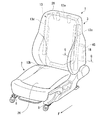
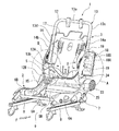
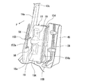
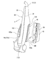
図1は、車両の前席左側に配置された車両用シート1を前部側斜め上方から見た斜視図であり、図2は、同車両用シート1の骨格部を前部側斜め上方から見た斜視図である。
車両用シート1は、乗員の臀部を支持するシートクッション2と、このシートクッション2の後端部に連結されて、乗員の腰部及び背部を支持するシートバック3と、そのシートバック3の上部に支持されて、乗員の頭部及び首部を支持する図示しないヘッドレストとを備えている。
Hereinafter, an embodiment of the present invention will be described with reference to the drawings. In the drawings, the arrow F indicates the front of the vehicle.
FIG. 1 is a perspective view of a vehicle seat 1 arranged on the left side of the front seat of the vehicle as seen from diagonally above the front side, and FIG. 2 shows the skeleton of the vehicle seat 1 from diagonally above the front side. FIG.
The vehicle seat 1 includes a seat cushion 2 that supports the occupant's buttocks, a seat back 3 that is connected to the rear end of the seat cushion 2 and supports the waist and back of the occupant, and an upper portion of the seat back 3. A headrest (not shown) that is supported and supports the head and neck of the occupant is provided.

シートクッション2は、図2に示すように、前後のパイプ材5A,5Bと側部のプレート材6A,6Bによって矩形枠状に形成されたクッションフレーム7を備え、そのクッションフレーム7がシートレール8,8を介して車体フロア9に前後スライド可能に取り付けられている。クッションフレーム7は、その上面側にウレタンフォーム等から成る図示しないパッド材が装着され、これらの外側が合成繊維や皮革等から成るシート表皮26(図1参照)によって覆われている。   As shown in FIG. 2, the seat cushion 2 includes a cushion frame 7 formed in a rectangular frame shape by front and rear pipe members 5A and 5B and side plate members 6A and 6B. The cushion frame 7 is a seat rail 8. , 8 is attached to the vehicle body floor 9 so as to be slidable back and forth. The cushion frame 7 is provided with a pad material (not shown) made of urethane foam or the like on the upper surface side, and the outside thereof is covered with a seat skin 26 (see FIG. 1) made of synthetic fiber or leather.

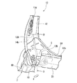
シートバック3は、図2に示すように、上部フレーム部13aと左右の側部フレーム部13c,13dと下部フレーム部13bとからなる略矩形枠形状のシートバックフレーム13を備えている。シートバックフレーム13は、その前面側にウレタンフォーム等から成るパッド材27(図11参照)が装着され、これらの外側が合成繊維や皮革等から成るシート表皮28(図1参照)によって覆われている。
上部フレーム部13aと下部フレーム部13bは車幅方向に延出するパイプ材によって形成され、左右の側部フレーム部13c,13dはパイプ材の外側に断面略コ字状のプレート材である側部プレート14a,14bが接合された構造とされている。各フレーム部13c,13a,13d,13bのパイプ材は一体の骨格パイプ12が略矩形状に曲げられて形成されている。
As shown in FIG. 2, the seat back 3 includes a substantially rectangular frame-shaped seat back frame 13 including an upper frame portion 13a, left and right side frame portions 13c and 13d, and a lower frame portion 13b. The seat back frame 13 is provided with a pad material 27 (see FIG. 11) made of urethane foam or the like on the front side thereof, and the outside thereof is covered with a seat skin 28 (see FIG. 1) made of synthetic fiber or leather. Yes.
The upper frame portion 13a and the lower frame portion 13b are formed of a pipe material extending in the vehicle width direction, and the left and right side frame portions 13c and 13d are side portions that are plate materials having a substantially U-shaped cross section outside the pipe material. The plates 14a and 14b are joined. The pipe material of each frame part 13c, 13a, 13d, 13b is formed by bending an integral skeleton pipe 12 into a substantially rectangular shape.

ただし、骨格パイプ12は、図2に示すように、一端12Aが車幅方向内側の側部フレーム部13d(以下、「内側側部フレーム部13d」と呼ぶ。)に位置され、他端12Bが下部フレーム部13bに位置され、その中間部が上部フレーム部13aと車幅方向外側の側部フレーム部13c(以下、「外側側部フレーム部13c」と呼ぶ。)に亙って延在しているが、骨格パイプ12の一端12Aは内側側部フレーム部13dの下端から所定距離上方に離間した位置から始まり、他端12Bは内側側部フレーム13dの手前で終わっている。つまり、骨格パイプ12の下部フレーム部13bを構成する部分は、内側側部フレーム部13dとの間に離間スペースSを形成している。
また、この実施形態の場合、外側側部フレーム部13cと内側側部フレーム部13dを構成する各側部プレート14a,14bは、それぞれ複数枚のプレート材が接合されて構成されている。
However, as shown in FIG. 2, the skeleton pipe 12 has one end 12 </ b> A positioned on the inner side frame portion 13 d (hereinafter referred to as “inner side portion frame portion 13 d”) and the other end 12 </ b> B. Located in the lower frame portion 13b, its intermediate portion extends over the upper frame portion 13a and the side frame portion 13c on the outer side in the vehicle width direction (hereinafter referred to as “outer side portion frame portion 13c”). However, one end 12A of the skeleton pipe 12 starts from a position spaced a predetermined distance above the lower end of the inner side frame portion 13d, and the other end 12B ends in front of the inner side frame 13d. That is, the part which comprises the lower frame part 13b of the frame | skeleton pipe 12 forms the separation space S between the inner side side frame parts 13d.
In the case of this embodiment, each of the side plates 14a and 14b constituting the outer side frame portion 13c and the inner side frame portion 13d is configured by joining a plurality of plate materials.

ところで、車幅方向外側と内側の各側部プレート14a,14bの下端は、下部フレーム部13bよりも下方まで延出しており、この各側部プレート14a,14bの下端の近傍が、クッションフレーム7の両側のプレート材6A,6Bの後端領域の内側に配置され、傾動軸15を介してクッションフレーム7の後端部に傾動可能に連結されている。この傾動軸15はリクライニング機構の軸を構成し、クッションフレーム7の両側のプレート材6A,6Bに跨るように車幅方向に沿って延出している。
なお、図中16,17は、シートバック3の図示しないパッド材を支持するために、外側側部フレーム部13cと内側側部フレーム部13dに取り付けられた支持マットと支持ワイヤである。
By the way, the lower ends of the side plates 14a and 14b on the outer side and the inner side in the vehicle width direction extend below the lower frame portion 13b, and the vicinity of the lower ends of the side plates 14a and 14b is the cushion frame 7. Are disposed inside the rear end regions of the plate members 6A and 6B on both sides thereof, and are connected to the rear end portions of the cushion frame 7 via the tilt shaft 15 so as to be tiltable. This tilting shaft 15 constitutes the axis of the reclining mechanism, and extends along the vehicle width direction so as to straddle the plate members 6A, 6B on both sides of the cushion frame 7.
Reference numerals 16 and 17 denote support mats and support wires attached to the outer side frame portion 13c and the inner side frame portion 13d in order to support a pad material (not shown) of the seat back 3.

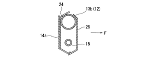
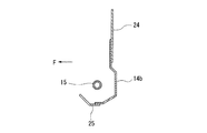
図3,図4は、外側側部フレーム部13cの下半領域と下部フレーム部13bの連設部の近傍を示す図であり、図5は、図3のC−C断面に対応する断面図である。また、図6は、内側側部フレーム部13dの下半領域と下部フレーム部13bの連設部の近傍を示す図であり、図7は、図6のD―D断面に対応する断面図である。
外側側部フレーム部13cを成す側部プレート14aの車幅方向外側の面には、車幅方向外側に突出して、側面衝突時等に車体側部(例えば、センターピラー)から入力された衝撃荷重をシートバックフレーム13に伝達する第1の荷重伝達ブロック18(荷重伝達ブロック)が取り付けられている。
3 and 4 are views showing the lower half region of the outer side frame portion 13c and the vicinity of the connecting portion of the lower frame portion 13b, and FIG. 5 is a cross-sectional view corresponding to the CC cross section of FIG. It is. FIG. 6 is a view showing the vicinity of the lower half region of the inner side frame portion 13d and the connecting portion of the lower frame portion 13b, and FIG. 7 is a cross-sectional view corresponding to the DD cross section of FIG. is there.
An impact load that protrudes outward in the vehicle width direction on the outer surface in the vehicle width direction of the side plate 14a forming the outer side frame portion 13c and is input from the vehicle body side portion (for example, the center pillar) at the time of a side collision or the like. Is attached to the seat back frame 13.

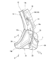
第1の荷重伝達ブロック18は、金属製の略矩形の半割り容器状の前部ブロック18Aと後部ブロック18Bの周縁部が相互に接合されて成り、上下方向に長い略長方形状の断面が車幅方向外側に向かって延出している。前部ブロック18Aの前面は、エアバッグ装置30(図1参照)が取り付けられる取付座18aとされ、また、前部ブロック18Aの車幅方向内側の縁部には上下に離間して一対の窪み部19,19が形成されている。前部ブロック18Aの内側の縁部はこの窪み部19,19によって上下方向に亙って波打ち、それによって車幅方向の剛性の向上が図られている。また、各窪み部19の底壁の車幅方向内側領域には、車幅方向内側に向かって突出する舌片部20(図4参照)が設けられている。
第1の荷重伝達ブロック18は、側部プレート14aの車幅方向外側の面に重ねられ、側部プレート14aとの当接部の周域が側部プレート14aに対して溶接によって固定されている。ただし、図4に示すように、側部プレート14a上の第1の荷重伝達ブロック18の舌片部20に対応する位置には、長孔状の貫通孔21,21が形成され、この貫通孔21,21を通して各舌片部20が骨格パイプ12に対して直接溶接固定されている。
The first load transmission block 18 is formed by joining the peripheral portions of a substantially rectangular half-divided container-shaped front block 18A and rear block 18B to each other, and has a substantially rectangular cross section that is long in the vertical direction. It extends outward in the width direction. The front surface of the front block 18A is a mounting seat 18a to which the airbag device 30 (see FIG. 1) is attached, and a pair of depressions are vertically spaced apart at the inner edge of the front block 18A in the vehicle width direction. Portions 19 and 19 are formed. The inner edge of the front block 18A is undulated in the vertical direction by the depressions 19 and 19, thereby improving the rigidity in the vehicle width direction. In addition, a tongue piece 20 (see FIG. 4) that protrudes inward in the vehicle width direction is provided in an inner region in the vehicle width direction of the bottom wall of each recess 19.
The first load transmission block 18 is overlaid on the outer surface of the side plate 14a in the vehicle width direction, and the peripheral area of the contact portion with the side plate 14a is fixed to the side plate 14a by welding. . However, as shown in FIG. 4, long hole-like through holes 21 and 21 are formed at positions corresponding to the tongue piece 20 of the first load transmitting block 18 on the side plate 14a. Each tongue piece 20 is directly fixed to the skeleton pipe 12 by welding through 21 and 21.

また、図4に示すように、クッションフレーム7の車幅方向外側のプレート材6Aの後端部には、傾動軸15の外周域を囲む円筒状のボス部22が突設され、このボス部22に第2の荷重伝達ブロック23が取り付けられている。この第2の荷重伝達ブロック23は、車両の側面衝突時等に車体側部の下部領域から入力された衝撃荷重をシートバックフレーム13の下端領域(傾動軸15の存在する領域)に直接伝達する部材であり、車幅方向に延出する複数の筒状断面が並列に配置されたハニカム構造とされ、全体が樹脂によって短軸円柱状に形成されている。   As shown in FIG. 4, a cylindrical boss portion 22 surrounding the outer peripheral area of the tilt shaft 15 protrudes from the rear end portion of the plate material 6 </ b> A on the outer side in the vehicle width direction of the cushion frame 7. A second load transmission block 23 is attached to 22. The second load transmission block 23 directly transmits the impact load input from the lower region of the side of the vehicle body to the lower end region of the seat back frame 13 (region where the tilting shaft 15 exists) at the time of a side collision of the vehicle. It is a member and has a honeycomb structure in which a plurality of cylindrical cross sections extending in the vehicle width direction are arranged in parallel, and the whole is formed into a short-axis columnar shape by a resin.

ところで、傾動軸15よりも上方に配置されている下部フレーム部13bには、シート幅方向の両縁部が外側側部フレーム部13cと内側側部フレーム部13dに結合された金属製のリヤアンダープレート24(板状強度部材)が結合されている。このリヤアンダープレート24は、上縁部が下部フレーム部13bの後部側上面に溶接固定され、図5に示すように、その溶接固定部から下方に延出する領域が傾動軸15の後方側を覆い、さらに下縁部が前方側に屈曲して傾動軸15の下方を覆うようになっている。この実施形態の場合、リヤアンダープレート24は傾動軸15よりも低い位置まで下端全域が延出している。また、リヤアンダープレート24の両側の下縁部は傾動軸15よりも低い位置を含む範囲で外側側部フレーム部13cと内側側部フレーム部13dの各側部プレート14a,14bに溶接固定されている。   By the way, the lower frame portion 13b disposed above the tilting shaft 15 has a metal rear underside in which both edges in the seat width direction are coupled to the outer side frame portion 13c and the inner side frame portion 13d. Plate 24 (plate-like strength member) is coupled. The rear under plate 24 is welded and fixed at the upper edge to the upper surface of the rear side of the lower frame portion 13b. As shown in FIG. 5, the region extending downward from the weld fixing portion is located on the rear side of the tilt shaft 15. Further, the lower edge portion is bent forward to cover the lower side of the tilting shaft 15. In the case of this embodiment, the rear lower plate 24 extends at its lower end to a position lower than the tilting shaft 15. Further, the lower edge portions of both sides of the rear under plate 24 are welded and fixed to the side plates 14a and 14b of the outer side frame portion 13c and the inner side frame portion 13d within a range including a position lower than the tilting shaft 15. Yes.

また、この実施形態の場合、下部フレーム部13bを構成する骨格パイプ12には、図3に示すように、外側側部フレーム部13c(側部プレート14a)に向かって斜め上方に屈曲する傾斜部12aが設けられている。リヤアンダープレート24の車幅方向外側の縁部は、この傾斜部12aに沿うようにその上端部の高さが側端部に向かって次第に高くなっている。なお、下部フレーム部13bを構成する骨格パイプ12の他端12Bは、図6に示すように、内側側部フレーム部13dまで延出していないが、リヤアンダープレート24の車幅方向内側の縁部は、車幅方向外側の縁部と同様に、その上端部の高さが側端部に向かって次第に高くなっている。   Further, in the case of this embodiment, the skeletal pipe 12 constituting the lower frame portion 13b has an inclined portion that bends obliquely upward toward the outer side frame portion 13c (side plate 14a) as shown in FIG. 12a is provided. The edge of the rear under plate 24 on the outer side in the vehicle width direction has its upper end gradually becoming higher toward the side end along the inclined portion 12a. As shown in FIG. 6, the other end 12B of the skeleton pipe 12 constituting the lower frame portion 13b does not extend to the inner side frame portion 13d. As with the outer edge in the vehicle width direction, the height of the upper end portion gradually increases toward the side end portion.

また、下部フレーム部13bと傾動軸15の前方側には、金属製のフロントアンダープレート25(板状補強部材)が配置されている。このフロントアンダープレート25は、図5に示すように、上端部が下部フレーム部13bの前部側上面に溶接固定されるとともに、シート幅方向の両縁部が外側側部フレーム部13cと内側側部フレーム部13dの各側部プレート14a,14bに溶接固定されている。なお、フロントアンダープレート25の上端部はリヤアンダープレート24の上端部に溶接固定するようにしても良い。そして、フロントアンダープレート25の下部フレーム部13bから下方に延出する領域は傾動軸15の前方側を覆い、さらに下縁部が傾動軸15よりも低い位置で後方側に屈曲して、傾動軸15の下方を覆う位置でリヤアンダープレート24の下端に溶接固定されている。なお、フロントアンダープレート25の車幅方向外側の縁部は、リヤアンダープレート24と同様に、その上端部の高さが側端部に向かって次第に高くなっているが、フロントアンダープレート25の車幅方向内側の縁部は、傾動軸15の前面から上面に亙る領域が切り欠かれている。   Further, a metal front under plate 25 (a plate-like reinforcing member) is disposed on the front side of the lower frame portion 13b and the tilting shaft 15. As shown in FIG. 5, the front under plate 25 has an upper end welded and fixed to the upper surface on the front side of the lower frame portion 13b, and both edges in the seat width direction are connected to the outer side frame portion 13c and the inner side. It is fixed by welding to each side plate 14a, 14b of the part frame part 13d. Note that the upper end portion of the front under plate 25 may be fixed to the upper end portion of the rear under plate 24 by welding. The region extending downward from the lower frame portion 13b of the front under plate 25 covers the front side of the tilt shaft 15, and the lower edge portion is bent backward at a position lower than the tilt shaft 15, so that the tilt shaft 15 is welded and fixed to the lower end of the rear under plate 24 at a position covering the lower portion of the rear under plate 24. Note that, as with the rear under plate 24, the edge of the front under plate 25 on the outer side in the vehicle width direction has an upper end that gradually increases in height toward the side end. A region extending from the front surface to the upper surface of the tilting shaft 15 is notched in the inner edge in the width direction.

フロントアンダープレート25は、図5に示すように、リヤアンダープレート24とともに車幅方向に延出する閉断面を構成している。このフロントアンダープレート25とリヤアンダープレート24とによる閉断面は、傾動軸15の周囲を覆い、かつ外側側部フレーム部13cと内側側部フレーム部13dの下端部同士を連結している。   As shown in FIG. 5, the front under plate 25 forms a closed cross section that extends in the vehicle width direction together with the rear under plate 24. The closed cross section of the front under plate 25 and the rear under plate 24 covers the periphery of the tilting shaft 15 and connects the lower end portions of the outer side frame portion 13c and the inner side frame portion 13d.

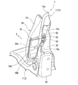
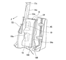
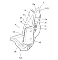
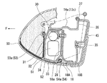
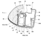
図8〜図10は、外側側部フレーム部13cと第1の荷重伝達ブロック18に他の部品が取り付けられる状態を示す斜視図であり、図11は、図1のG−G断面に対応する断面図である。
これらの図に示すように、第1の荷重伝達ブロック18の前面側にはエアバッグ装置30が取り付けられ、第1の荷重伝達ブロック18の後面側には、樹脂製のカバー部材45が取り付けられている。
8 to 10 are perspective views showing a state in which other components are attached to the outer side frame portion 13c and the first load transmission block 18, and FIG. 11 corresponds to the GG section of FIG. It is sectional drawing.
As shown in these drawings, an airbag device 30 is attached to the front side of the first load transmission block 18, and a resin cover member 45 is attached to the rear side of the first load transmission block 18. ing.

エアバッグ装置30は、図11に示すように、衝撃を感知してガスを発生するイフレータ31と、インフレータ31のガス圧を受けて展開する折り畳まれた袋体32を備え、これらが上下方向に長尺なバッグケース33に収容されている。バッグケース33は、車体前方に指向する前面が、袋体32の展開により、側部プレート14a側のコーナーをヒンジ支点として展開口34を前方側に開く蓋部とされている。バッグケース33は、その後面が第1の荷重伝達ブロック18の前部ブロック18Aの前面の取付座18aにボルトナット等の固定手段によって固定されている。   As shown in FIG. 11, the airbag device 30 includes an inflator 31 that generates a gas upon sensing an impact, and a folded bag body 32 that is expanded by receiving the gas pressure of the inflator 31, and these are vertically arranged. It is accommodated in a long bag case 33. The front surface of the bag case 33 directed to the front of the vehicle body is a lid portion that opens the deployment opening 34 forward with the corner on the side plate 14 a side as a hinge fulcrum by the deployment of the bag body 32. The rear surface of the bag case 33 is fixed to a mounting seat 18a on the front surface of the front block 18A of the first load transmission block 18 by a fixing means such as a bolt and nut.

一方、カバー部材45は、第1の荷重伝達ブロック18よりも一回り大きい正面視が略長方形状の半割りの箱型形状に形成され、第1の荷重伝達ブロック18の後面と周囲を覆った状態で第1の荷重伝達ブロック18の背面にビス35によって固定されるようになっている。カバー部材45の外面は滑らかな面によって形成されている。また、カバー部材45は、第1の荷重伝達ブロック18の背面にビス止めされるに際して、側部プレート14aの後部側の屈曲壁36の後面に跨って固定される。カバー部材45は、このようにして取り付けられると、側部プレート14aの後部からエアバッグ装置30のバッグケース33の外端部の近傍部にかけてを滑らかな面によって覆うことになる。   On the other hand, the cover member 45 is formed in a substantially rectangular half-box shape in front view that is slightly larger than the first load transmission block 18 and covers the rear surface and the periphery of the first load transmission block 18. In this state, it is fixed to the back surface of the first load transmission block 18 with screws 35. The outer surface of the cover member 45 is formed by a smooth surface. Further, when the cover member 45 is screwed to the back surface of the first load transmission block 18, the cover member 45 is fixed across the rear surface of the bent wall 36 on the rear side of the side plate 14a. When the cover member 45 is attached in this manner, the cover member 45 is covered with a smooth surface from the rear portion of the side plate 14a to the vicinity of the outer end portion of the bag case 33 of the airbag device 30.

ところで、側部プレート14aとエアバッグ装置30の前面側には、図11に示すようにパッド材27が配置され、このパッド材27の外面側がシート表皮28によって覆われている。そして、パッド材27を覆ったシート表皮28の車幅方向外側の端縁は、バッグケース33とカバー部材45の外側面をさらに覆い、側部プレート14aの後端に係止部材37を介して係止されている。このとき、カバー部材45は、エアバッグ装置30から側部プレート14aの後端に亙る領域においてシート表皮28の形状出しを行う(皺のない連続形状を作り出す)ように機能する。   Incidentally, as shown in FIG. 11, a pad material 27 is disposed on the side plate 14 a and the front side of the airbag device 30, and the outer surface side of the pad material 27 is covered with a seat skin 28. The outer edge of the seat skin 28 covering the pad material 27 in the vehicle width direction further covers the outer surfaces of the bag case 33 and the cover member 45, and the rear end of the side plate 14 a via the locking member 37. It is locked. At this time, the cover member 45 functions to shape the sheet skin 28 (create a continuous shape without wrinkles) in a region extending from the airbag device 30 to the rear end of the side plate 14a.

また、シート表皮28のうちのバッグケース33の展開口34の前方側位置には、図11に示すように、エアバッグ装置30の袋体32の展開時に、展開圧によって破断される破断境界部50が上下方向に沿うように設けられている。そして、シート表皮28の裏面のうちの、破断境界部50のシート幅方向内側の縁部と外側の縁部には、内側力布51と外側力布52がそれぞれ縫合されている。内側力布51と外側力布52は、エアバッグ装置30の展開時に破断境界部50の両縁に張力を付与して、破断境界部50からの破断を促すための布部材であり、これらの各基端部は内側支持ワイヤ53と外側支持ワイヤ54を介して外側側部フレーム部13cに連結されている。   Further, as shown in FIG. 11, at the position on the front side of the deployment opening 34 of the bag case 33 in the seat skin 28, a fracture boundary portion that is broken by the deployment pressure when the bag body 32 of the airbag device 30 is deployed. 50 is provided along the vertical direction. The inner force cloth 51 and the outer force cloth 52 are stitched to the inner edge and the outer edge of the breaking boundary 50 on the back surface of the sheet skin 28, respectively. The inner force cloth 51 and the outer force cloth 52 are cloth members for applying a tension to both edges of the break boundary portion 50 when the airbag device 30 is deployed to promote breakage from the break boundary portion 50. Each base end portion is connected to the outer side frame portion 13 c via the inner support wire 53 and the outer support wire 54.

外側側部フレーム部13cの側部プレート14aには、図8に示すように、シート幅方向の内側に膨出するように支持フレーム55が取り付けられ、この支持フレーム55に内側支持ワイヤ53と外側支持ワイヤ54の各基端部が固定されている。   As shown in FIG. 8, a support frame 55 is attached to the side plate 14a of the outer side frame portion 13c so as to bulge inward in the seat width direction, and the inner support wire 53 and the outer side are attached to the support frame 55. Each base end portion of the support wire 54 is fixed.

内側支持ワイヤ53は、図9に示すように、内側力布51が取り付けられる取付部53aが、側部プレート14aの前方側に配置されるとともに、取付部53aを挟む上下の端部が側部プレート14aの内側面に沿って後方側に延出し、その状態で後方側の支持フレーム55に固定されている。   As shown in FIG. 9, the inner support wire 53 has an attachment portion 53 a to which the inner force cloth 51 is attached disposed on the front side of the side plate 14 a and upper and lower ends sandwiching the attachment portion 53 a are side portions. The plate 14a extends rearward along the inner surface of the plate 14a, and is fixed to the rear support frame 55 in this state.

一方、外側支持ワイヤ54は、外側力布52が取り付けられる取付部54aが、第1の荷重伝達ブロック18の車幅方向外側の前端領域に配置されるとともに、取付部54aを挟む上下の端部が、第1の荷重伝達ブロック18の後面(後部ブロック18Bの後面)に這わせて後方側の支持フレーム55に固定されている。外側支持ワイヤ54の第1の荷重伝達ブロック18の後面に這わせる部分は、カバー部材45が第1の荷重伝達ブロック18に固定されるときに、カバー部材45と第1の荷重伝達ブロック18との間で挟持される。   On the other hand, the outer support wire 54 has an attachment portion 54a to which the outer force cloth 52 is attached disposed in a front end region on the outer side in the vehicle width direction of the first load transmission block 18, and upper and lower end portions sandwiching the attachment portion 54a. Is fixed to the support frame 55 on the rear side along the rear surface of the first load transmission block 18 (the rear surface of the rear block 18B). The portion of the outer support wire 54 that hangs on the rear surface of the first load transmission block 18 is configured such that when the cover member 45 is fixed to the first load transmission block 18, the cover member 45, the first load transmission block 18, Sandwiched between.

以上の構成において、車両の側面衝突時に衝撃荷重が車体側部に入力され、車体側部が車幅方向内側に変形すると、その変形した車体側部が第1の荷重伝達ブロック18と第2の荷重伝達ブロック23のうちの少なくとも一方に当接し、衝撃荷重がシートバックフレーム13の外側側部フレーム部13cに伝達される。   In the above configuration, when the impact load is input to the vehicle body side portion at the time of a side collision of the vehicle and the vehicle body side portion is deformed inward in the vehicle width direction, the deformed vehicle body side portion is connected to the first load transmission block 18 and the second load transmission block 18. It abuts against at least one of the load transmission blocks 23, and the impact load is transmitted to the outer side frame portion 13c of the seat back frame 13.

こうして、外側側部フレーム部13cに衝撃荷重が入力されると、車幅方向に延出するリヤアンダープレート24とフロントアンダープレート25が、その衝撃荷重を下部フレーム部13bとともに内側側部フレーム部13dの下端に伝達する。内側側部フレーム部13dに伝達された荷重は、シートバックフレーム13全体の車幅方向内側への移動とともに車幅方向中央のコンソールボックス(図示せず)を介してフロアトンネル(図示せず)に速やかに伝達される。   Thus, when an impact load is input to the outer side frame portion 13c, the rear under plate 24 and the front under plate 25 extending in the vehicle width direction cause the impact load to be applied to the inner side frame portion 13d together with the lower frame portion 13b. Is transmitted to the lower end. The load transmitted to the inner side frame portion 13d moves to the floor tunnel (not shown) through the console box (not shown) at the center in the vehicle width direction along with the movement of the entire seatback frame 13 toward the inside in the vehicle width direction. Promptly communicated.

一方、車両の側面衝突時に衝撃がセンサによって感知されると、エアバッグ装置30のインフレータ31がガスを発生して袋体32を前方に展開させる。こうして袋体32が展開すると、バッグケース33の展開口34が開いて袋体32が内側力布51と外側力布52の間を前進し、このときの展開圧が内側力布51と外側力布52を通してシート表皮28の破断境界部50に作用し、シート表皮28がこの部位で破断することになる。これにより、袋体32がシートバック3の車幅方向外側の側部で前方に展開し、シートに着座した乗員の側部が袋体32によって保護される。   On the other hand, when an impact is detected by the sensor at the time of a side collision of the vehicle, the inflator 31 of the airbag device 30 generates gas and deploys the bag body 32 forward. When the bag body 32 is deployed in this manner, the deployment port 34 of the bag case 33 is opened, and the bag body 32 advances between the inner force cloth 51 and the outer force cloth 52, and the unfolding pressure at this time is changed between the inner force cloth 51 and the outer force cloth 51. The cloth 52 acts on the break boundary portion 50 of the sheet skin 28, and the sheet skin 28 is broken at this portion. As a result, the bag body 32 is unfolded forward at the outer side of the seat back 3 in the vehicle width direction, and the side of the occupant seated on the seat is protected by the bag body 32.

以上のように、この車両用シート1は、第1の荷重伝達ブロック18が、複雑に入り組んだ凹凸形状を持つ金属成形品を組み合わせて構成されているにも拘わらず、この第1の荷重伝達ブロック18の背面側に樹脂製のカバー部材45が取付けられているため、第1の荷重伝達ブロック18の背部側から側方に亙る領域にシート表皮28の皺が発生するのを未然に防止することができる。したがって、車両用シート1を採用することにより、外観品質を向上させることができる。   As described above, the vehicle seat 1 has the first load transmission block 18 in spite of the fact that the first load transmission block 18 is configured by combining the metal moldings having complicated uneven shapes. Since the resin cover member 45 is attached to the back side of the block 18, it is possible to prevent the sheet skin 28 from being wrinkled in the region extending from the back side to the side of the first load transmission block 18. be able to. Therefore, by adopting the vehicle seat 1, the appearance quality can be improved.

図12〜図15は、この発明の他の実施形態を示すものである。この他の実施形態
は、内側力布51と外側力布52の取付部の構造が異なるだけで、他の部分は上記の実施形態とほぼ同様の構造とされている。したがって、上記の実施形態と同一部分に同一符号を付して重複する説明を省略するものとする。
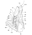
図12〜図14は、外側側部フレーム部13cと第1の荷重伝達ブロック18に他の部品が取り付けられる状態を示す斜視図であり、図15は、図1のG−G断面に対応する断面図である。
第1の荷重伝達ブロック18の前面側と後面側には、上記の実施形態と同様のエアバッグ装置30と樹脂製のカバー部材45がそれぞれ取り付けられている。
12 to 15 show another embodiment of the present invention. In this other embodiment, only the structure of the attachment portion of the inner force cloth 51 and the outer force cloth 52 is different, and the other parts are substantially the same as those in the above embodiment. Accordingly, the same parts as those in the above embodiment are denoted by the same reference numerals and redundant description is omitted.
12 to 14 are perspective views showing a state in which other parts are attached to the outer side frame portion 13c and the first load transmission block 18, and FIG. 15 corresponds to the GG section of FIG. It is sectional drawing.
The airbag device 30 and the resin cover member 45 similar to those of the above-described embodiment are attached to the front and rear surfaces of the first load transmission block 18, respectively.

図15に示すように、内側力布51と外側力布52の各端部は、内側支持ワイヤ153と外側支持ワイヤ154を介して外側側部フレーム部13cに支持されているが、内側支持ワイヤ153は外側側部フレーム部13cの側部プレート14aに係止固定され、外側支持ワイヤ154は第1の荷重伝達ブロック18に係止固定されている。   As shown in FIG. 15, each end portion of the inner force cloth 51 and the outer force cloth 52 is supported by the outer side frame portion 13c via the inner support wire 153 and the outer support wire 154. 153 is locked and fixed to the side plate 14 a of the outer side frame portion 13 c, and the outer support wire 154 is locked and fixed to the first load transmission block 18.

内側支持ワイヤ153は、図13に示すように、内側力布51が取り付けられる取付部153aが、側部プレート14aの前方側に配置されるとともに、取付部153aを挟む上下の端部が、側部プレート14aに設けられた一対の長孔状の係止孔56,56に車幅方向外側から挿入されている。側部プレート14aの係止孔156,156は、エアバッグ装置30に隣接する部位に上下に離間して設けられている。内側支持ワイヤ153の上下の各端部には、図15に示すように、略U字状の係止フック153bが設けられ、その各係止フック153bが対応する係止孔56の前側の縁部に係止されている。係止孔56,56は、内側支持ワイヤ153を側部プレート14a(外側側部フレーム部13c)の外側面に当接させた状態で係止するワイヤ係止部を構成している。内側支持ワイヤ153のうちの、係止孔56,56から車幅方向外側に引き出されて取付部153aに連続する部位は側部プレート14aの外側面に沿って前方に延出しているが、この部位は、図14に示すように、第1の荷重伝達ブロック18に固定されるエアバッグ装置30のバッグケース33と側部プレート14aとの間で挟持される。   As shown in FIG. 13, the inner support wire 153 has an attachment portion 153a to which the inner force cloth 51 is attached arranged on the front side of the side plate 14a, and upper and lower ends sandwiching the attachment portion 153a are on the side. A pair of elongated holes 56, 56 provided in the part plate 14a are inserted from the outside in the vehicle width direction. The locking holes 156 and 156 of the side plate 14 a are provided at a position adjacent to the airbag device 30 so as to be separated from each other in the vertical direction. As shown in FIG. 15, a substantially U-shaped locking hook 153b is provided at each of the upper and lower ends of the inner support wire 153, and each locking hook 153b has a front edge of the corresponding locking hole 56. It is locked to the part. The locking holes 56 and 56 constitute a wire locking portion that locks the inner support wire 153 in a state where the inner support wire 153 is in contact with the outer surface of the side plate 14a (outer side frame portion 13c). The portion of the inner support wire 153 that is drawn out from the locking holes 56 and 56 outward in the vehicle width direction and continues to the attachment portion 153a extends forward along the outer surface of the side plate 14a. As shown in FIG. 14, the portion is sandwiched between the bag case 33 of the airbag device 30 fixed to the first load transmission block 18 and the side plate 14a.

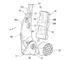
一方、外側支持ワイヤ154は、図12に示すように、外側力布52が取り付けられる取付部154aが、第1の荷重伝達ブロック18の車幅方向外側の前端領域に配置されるとともに、取付部154aを挟む上下の各端部が第1の荷重伝達ブロック18の後面(後部ブロック18Bの後面)に這わせて配置され、その各端部が第1の荷重伝達ブロック18の後面に係止固定されている。具体的には、外側支持ワイヤ154の各端部には、略L字状に屈曲した係止フック154bが設けられ、この各係止フック154bが第1の荷重伝達ブロック18の後部面に設けられた対応する係止孔57に挿入され、その各係止孔57の縁部に係止されている。   On the other hand, as shown in FIG. 12, the outer support wire 154 has an attachment portion 154 a to which the outer force cloth 52 is attached arranged in the front end region on the outer side in the vehicle width direction of the first load transmission block 18. The upper and lower ends sandwiching 154a are arranged over the rear surface of the first load transmission block 18 (the rear surface of the rear block 18B), and the respective end portions are locked and fixed to the rear surface of the first load transmission block 18. Has been. Specifically, each end portion of the outer support wire 154 is provided with a locking hook 154 b bent in a substantially L shape, and each locking hook 154 b is provided on the rear surface of the first load transmission block 18. It is inserted into the corresponding locking hole 57 and locked to the edge of each locking hole 57.

第1の荷重伝達ブロック18の後部面には、図12に示すように、上下に離間して一対の開口58,58が設けられている。上記の各係止孔57は、この各開口58に連続するように各開口58の車幅方向外側の辺に溝状に連続して形成されている。外側支持ワイヤ154の係止フック154bは開口58側から係止孔57内に案内され、各係止孔57の縁部に係止されている。外側支持ワイヤ154の第1の荷重伝達ブロック18の後面に這わせた部分は、カバー部材45が第1の荷重伝達ブロック18に固定されるときに、カバー部材45と第1の荷重伝達ブロック18との間で挟持される。
なお、カバー部材45の裏面(第1の荷重伝達ブロック18の後面に対向する側の面)には、図13に示すように、上下方向に延出する補強リブ59が設けられている。この補強リブ59は、カバー部材45が第1の荷重伝達ブロック18に固定されたときに、外側支持ワイヤ154の各係止フック154bの付根部の内側の近傍に配置され、各係止フック154bの開口58方向への変位を規制する。
As shown in FIG. 12, a pair of openings 58 and 58 are provided on the rear surface of the first load transmission block 18 so as to be spaced apart from each other in the vertical direction. Each of the locking holes 57 is continuously formed in a groove shape on the outer side in the vehicle width direction of each opening 58 so as to be continuous with each opening 58. The locking hook 154 b of the outer support wire 154 is guided into the locking hole 57 from the opening 58 side and locked to the edge of each locking hole 57. The portion of the outer support wire 154 that extends over the rear surface of the first load transmission block 18 is arranged such that when the cover member 45 is fixed to the first load transmission block 18, the cover member 45 and the first load transmission block 18. Is sandwiched between.
A reinforcing rib 59 extending in the vertical direction is provided on the back surface of the cover member 45 (the surface facing the rear surface of the first load transmission block 18), as shown in FIG. When the cover member 45 is fixed to the first load transmission block 18, the reinforcing rib 59 is disposed in the vicinity of the inside of the root portion of each locking hook 154b of the outer support wire 154, and each locking hook 154b. The displacement in the direction of the opening 58 is regulated.

ここで、上記の各実施形態から抽出し得る他の発明について以下に列記する。
(a) 特許請求の範囲の請求項1に記載の車両用シートにおいて、
前記シートバックフレームの車幅方向外側の側部フレーム部に設置されるとともに、前記荷重伝達ブロックよりも前方側に展開口(例えば、実施形態の展開口34)を有するエアバッグ装置(例えば、実施形態のエアバッグ装置30)を備え、
前記荷重伝達ブロックの前面に、前記エアバッグ装置の取付座(例えば、実施形態の取付座18a)が設けられていることを特徴とする車両用シート。
(b) 前記(a)に記載の車両用シートにおいて、
前記エアバッグ装置が、前記シートバックフレームと荷重伝達ブロックとともに前記シート表皮によって覆われるともに、
前記シート表皮の前記エアバッグ装置の前方位置に設けられて前記エアバッグ装置の展開により破断される破断境界部(例えば、実施形態の破断境界部50)と、
前記シート表皮の前記破断境界部のシート幅方向内側の縁部と前記車幅方向外側の側部フレーム部とを連結する内側力布(例えば、実施形態の内側力布51)と、
前記シート表皮の前記破断境界部のシート幅方向外側の縁部と前記車幅方向外側の側部フレーム部または前記荷重伝達ブロックとを連結する外側力布(例えば、実施形態の外側力布52)と、
前記外側力布を前記車幅方向外側の側部フレーム部または前記荷重伝達ブロックに係止させる支持ワイヤ(例えば、実施形態の外側支持ワイヤ54)と、を備え、
前記支持ワイヤが、前記荷重伝達ブロックと前記カバー部材の間から車幅方向外側に引き出され、当該支持ワイヤの引き出された部位に前記外側力布が支持されていることを特徴とする車両用シート。
Here, other inventions that can be extracted from each of the above embodiments are listed below.
(A) In the vehicle seat according to claim 1 of the claims,
An airbag device (for example, an implementation) that is installed on a side frame portion on the vehicle width direction outer side of the seat back frame and has a deployment port (for example, the deployment port 34 of the embodiment) on the front side of the load transmission block. An airbag device 30) in the form of
A vehicle seat, wherein a mounting seat (for example, the mounting seat 18a of the embodiment) of the airbag device is provided on the front surface of the load transmission block.
(B) In the vehicle seat according to (a),
While the airbag device is covered by the seat skin together with the seat back frame and the load transmission block,
A break boundary portion (for example, a break boundary portion 50 of the embodiment) provided at a position in front of the airbag device of the seat skin and broken by deployment of the airbag device;
An inner force cloth (for example, the inner force cloth 51 of the embodiment) that connects an edge portion in the seat width direction of the rupture boundary portion of the seat skin and a side frame portion on the outer side in the vehicle width direction;
An outer webbing (for example, the outer webbing 52 of the embodiment) that connects an edge on the outer side in the seat width direction of the rupture boundary part of the seat skin and the side frame part or the load transmission block on the outer side in the vehicle width direction. When,
A support wire (for example, the outer support wire 54 of the embodiment) for locking the outer force cloth to the side frame portion or the load transmission block on the outer side in the vehicle width direction,
The vehicle seat, wherein the support wire is pulled out in the vehicle width direction from between the load transmission block and the cover member, and the outer force cloth is supported at a portion where the support wire is pulled out. .

なお、この発明は上記の実施形態に限定されるものではなく、その要旨を逸脱しない範囲で種々の設計変更が可能である。   In addition, this invention is not limited to said embodiment, A various design change is possible in the range which does not deviate from the summary.

1…車両用シート
3…シートバック
13…シートバックフレーム
13c…側部フレーム部
18…第1の荷重伝達ブロック(荷重伝達ブロック)
28…シート表皮
45…カバー部材
DESCRIPTION OF SYMBOLS 1 ... Vehicle seat 3 ... Seat back 13 ... Seat back frame 13c ... Side part frame part 18 ... 1st load transmission block (load transmission block)
28 ... Sheet skin 45 ... Cover member

Claims (1)

シートバックの外側骨格部をなすシートバックフレームと、
該シートバックフレームの車幅方向外側の側部フレーム部に設置されて、車体側部から入力された衝撃荷重を前記シートバックフレームに伝達する荷重伝達ブロックと、
前記シートバックフレームと前記荷重伝達ブロックの外側を覆うシート表皮と、を備えた車両用シートにおいて、
前記荷重伝達ブロックの背面側に前記シート表皮の形状だしを行うカバー部材が設けられていることを特徴とする車両用シート。
A seat back frame forming the outer skeleton of the seat back;
A load transmission block that is installed on a side frame portion on the outer side in the vehicle width direction of the seat back frame and transmits an impact load input from a vehicle body side portion to the seat back frame;
In the vehicle seat comprising the seat back frame and a seat skin covering the outside of the load transmission block,
A vehicular seat characterized in that a cover member is provided on the back side of the load transmission block for performing the shape of the seat skin.
JP2010209494A 2010-09-17 2010-09-17 Vehicle seat Expired - Fee Related JP5538155B2 (en)

Priority Applications (1)

Application Number Priority Date Filing Date Title
JP2010209494A JP5538155B2 (en) 2010-09-17 2010-09-17 Vehicle seat

Applications Claiming Priority (1)

Application Number Priority Date Filing Date Title
JP2010209494A JP5538155B2 (en) 2010-09-17 2010-09-17 Vehicle seat

Publications (2)

Publication Number Publication Date
JP2012062008A true JP2012062008A (en) 2012-03-29
JP5538155B2 JP5538155B2 (en) 2014-07-02

Family

ID=46058166

Family Applications (1)

Application Number Title Priority Date Filing Date
JP2010209494A Expired - Fee Related JP5538155B2 (en) 2010-09-17 2010-09-17 Vehicle seat

Country Status (1)

Country Link
JP (1) JP5538155B2 (en)

Citations (2)

* Cited by examiner, † Cited by third party
Publication number Priority date Publication date Assignee Title
JP2003159161A (en) * 2001-11-29 2003-06-03 Tachi S Co Ltd Seat and back that can be tilted back and forth
JP2010018190A (en) * 2008-07-11 2010-01-28 Honda Motor Co Ltd Vehicle seat

Patent Citations (2)

* Cited by examiner, † Cited by third party
Publication number Priority date Publication date Assignee Title
JP2003159161A (en) * 2001-11-29 2003-06-03 Tachi S Co Ltd Seat and back that can be tilted back and forth
JP2010018190A (en) * 2008-07-11 2010-01-28 Honda Motor Co Ltd Vehicle seat

Also Published As

Publication number Publication date
JP5538155B2 (en) 2014-07-02

Similar Documents

Publication Publication Date Title
JP5550646B2 (en) Vehicle seat
CN102310794B (en) Seat back frame
US9849856B1 (en) Side airbag energy management system
JP2010018191A (en) Load transmission body for vehicle
JP2010228561A (en) Reinforcement structure
JP2019031166A (en) Vehicle seat
JP5564375B2 (en) Vehicle seat
JP5852709B2 (en) Vehicle seat
JP5538155B2 (en) Vehicle seat
JP5563393B2 (en) Vehicle seat
JP5538154B2 (en) Vehicle seat
JP2014028590A (en) Vehicle seat
JP5202580B2 (en) Vehicle seat
JP5410859B2 (en) Seat back frame for vehicle seat
JP5548515B2 (en) Vehicle seat
JP4673415B2 (en) Vehicle seat
JP2009154851A (en) Load transmission structure between vehicle seats
JP5277205B2 (en) Seat back frame structure
JP5123902B2 (en) Seat back frame for vehicle seat
JP5577204B2 (en) Vehicle seat
JP5572461B2 (en) Vehicle seat
JP7259735B2 (en) seat side shield
JP2011131755A (en) Mounting structure of side airbag
JP4712881B2 (en) Vehicle seat
JP2019031165A (en) Vehicle seat

Legal Events

Date Code Title Description
A621 Written request for application examination

Free format text: JAPANESE INTERMEDIATE CODE: A621

Effective date: 20121206

A977 Report on retrieval

Free format text: JAPANESE INTERMEDIATE CODE: A971007

Effective date: 20131227

A131 Notification of reasons for refusal

Free format text: JAPANESE INTERMEDIATE CODE: A131

Effective date: 20140107

A521 Request for written amendment filed

Free format text: JAPANESE INTERMEDIATE CODE: A523

Effective date: 20140310

TRDD Decision of grant or rejection written
A01 Written decision to grant a patent or to grant a registration (utility model)

Free format text: JAPANESE INTERMEDIATE CODE: A01

Effective date: 20140401

R150 Certificate of patent or registration of utility model

Ref document number: 5538155

Country of ref document: JP

Free format text: JAPANESE INTERMEDIATE CODE: R150

A61 First payment of annual fees (during grant procedure)

Free format text: JAPANESE INTERMEDIATE CODE: A61

Effective date: 20140428

R250 Receipt of annual fees

Free format text: JAPANESE INTERMEDIATE CODE: R250

R250 Receipt of annual fees

Free format text: JAPANESE INTERMEDIATE CODE: R250

R250 Receipt of annual fees

Free format text: JAPANESE INTERMEDIATE CODE: R250

R250 Receipt of annual fees

Free format text: JAPANESE INTERMEDIATE CODE: R250

R250 Receipt of annual fees

Free format text: JAPANESE INTERMEDIATE CODE: R250

R250 Receipt of annual fees

Free format text: JAPANESE INTERMEDIATE CODE: R250

LAPS Cancellation because of no payment of annual fees