JP2012058749A - Lubricant supply device, cleaning device, process cartridge, and image forming apparatus - Google Patents
Lubricant supply device, cleaning device, process cartridge, and image forming apparatus Download PDFInfo
- Publication number
- JP2012058749A JP2012058749A JP2011241964A JP2011241964A JP2012058749A JP 2012058749 A JP2012058749 A JP 2012058749A JP 2011241964 A JP2011241964 A JP 2011241964A JP 2011241964 A JP2011241964 A JP 2011241964A JP 2012058749 A JP2012058749 A JP 2012058749A
- Authority
- JP
- Japan
- Prior art keywords
- lubricant
- supply device
- brush
- lubricant supply
- image carrier
- Prior art date
- Legal status (The legal status is an assumption and is not a legal conclusion. Google has not performed a legal analysis and makes no representation as to the accuracy of the status listed.)
- Pending
Links
Images


Abstract
Description
この発明は、複写機、プリンタ、ファクシミリ、又は、それらの複合機等の電子写真方式を用いた画像形成装置に設置される感光体ドラム、感光体ベルト、中間転写ベルト等の像担持体上に潤滑剤を供給する潤滑剤供給装置と、それを備えたクリーニング装置、プロセスカートリッジ、及び、画像形成装置と、に関するものである。 The present invention is provided on an image carrier such as a photoconductor drum, a photoconductor belt, and an intermediate transfer belt installed in an image forming apparatus using an electrophotographic system such as a copying machine, a printer, a facsimile, or a composite machine thereof. The present invention relates to a lubricant supply device that supplies a lubricant, and a cleaning device, a process cartridge, and an image forming apparatus including the lubricant supply device.
従来から、複写機、プリンタ等の画像形成装置では、感光体ドラム等の像担持体上に付着する未転写トナー等の付着物をクリーニング装置で確実に清掃するとともに、像担持体やクリーニングブレード等の磨耗を低減するために、像担持体上に潤滑剤を供給する潤滑剤供給装置を用いる技術が知られている(例えば、特許文献1等参照。)。 2. Description of the Related Art Conventionally, in image forming apparatuses such as copying machines and printers, deposits such as untransferred toner adhering to an image carrier such as a photosensitive drum are reliably cleaned with a cleaning device, and an image carrier, a cleaning blade, and the like In order to reduce the wear of the toner, a technique using a lubricant supply device that supplies a lubricant onto the image carrier is known (see, for example, Patent Document 1).
詳しくは、転写工程後の像担持体上に残留する未転写トナーは、像担持体に当接するクリーニングブレード(クリーニング装置)によってすべて除去されるべきものである。しかし、クリーニングブレードが像担持体との当接によって経時劣化(磨耗)した場合には、未転写トナーが磨耗したクリーニングブレードと像担持体との隙間をすり抜けてクリーニング不良が生じることがあった。また、クリーニングブレードに劣化が生じていなくても、小粒径トナーや球形トナーを用いた場合には、そのトナーがクリーニングブレードと像担持体との僅かな隙間に入り込んでやがてその隙間をすり抜けてクリーニング不良が生じることがあった。さらに、トナーやトナー中に含まれる外添剤や紙粉等の付着物がクリーニングブレードと像担持体との隙間をすり抜けると、それが像担持体上に膜状に固着してフィルミングが生じることもあった。 Specifically, the untransferred toner remaining on the image carrier after the transfer process should be completely removed by a cleaning blade (cleaning device) that contacts the image carrier. However, when the cleaning blade deteriorates with time due to contact with the image carrier (abrasion), cleaning failure may occur due to slipping through the gap between the cleaning blade where the untransferred toner is worn and the image carrier. Even when the cleaning blade is not deteriorated, when small toner or spherical toner is used, the toner enters a slight gap between the cleaning blade and the image carrier and eventually passes through the gap. A cleaning failure sometimes occurred. Furthermore, if toner or an external additive or paper dust contained in the toner slips through the gap between the cleaning blade and the image carrier, it adheres to the image carrier and forms a film. There was also.
このような問題に対して、像担持体上に潤滑剤を塗布することで、像担持体上の摩擦係数が低下してクリーニングブレードや像担持体の劣化が低減されるとともに、像担持体上に付着する未転写トナー等の付着物の離脱性が向上されるために、経時におけるクリーニング不良やフィルミングの発生を抑止することができる。 In response to such a problem, by applying a lubricant on the image carrier, the friction coefficient on the image carrier is reduced, so that deterioration of the cleaning blade and the image carrier is reduced. Since the removability of deposits such as untransferred toner adhering to the toner is improved, it is possible to suppress the occurrence of poor cleaning and filming over time.
具体的に、特許文献1等において、潤滑剤供給装置(塗布部材)は、像担持体に摺接するブラシ状回転部材(ブラシ部)、ブラシ状回転部材に当接する固形潤滑剤、固形潤滑剤をブラシ状回転部材に向けて付勢するスプリング、等で構成される。そして、所定方向に回転するブラシ状回転部材によって固形潤滑剤から潤滑剤が徐々に削り取られて、ブラシ状回転部材によって削り取られた潤滑剤が像担持体の表面に塗布(供給)される。 Specifically, in Patent Document 1 and the like, the lubricant supply device (application member) includes a brush-like rotating member (brush portion) that makes sliding contact with the image carrier, a solid lubricant that contacts the brush-like rotating member, and a solid lubricant. It is composed of a spring that urges the brush-like rotating member. Then, the lubricant is gradually scraped off from the solid lubricant by the brush-like rotating member rotating in a predetermined direction, and the lubricant scraped off by the brush-like rotating member is applied (supplied) to the surface of the image carrier.
一方、特許文献2等には、中間転写ベルト上に潤滑剤を供給する潤滑剤供給装置であって、中間転写ベルトに当接するクリーニングブレードを用いて、ブラシ状回転部材(ブラシ)によって中間転写ベルトに供給された潤滑剤が飛散するのを防止する技術が開示されている。
On the other hand,
従来の潤滑剤供給装置において、ブラシ状回転部材に担持された潤滑剤は、そのすべてが像担持体上に供給されずに、一部がブラシ状回転部材から離脱して飛散してしまっていた。そして、飛散した潤滑剤が画像形成装置内を汚染してしまっていた。 In the conventional lubricant supply device, all of the lubricant carried on the brush-like rotating member is not supplied onto the image carrier, and a part of the lubricant is separated from the brush-like rotating member and scattered. . The scattered lubricant has contaminated the image forming apparatus.
一方、特許文献2等の技術は、中間転写ベルトに当接するクリーニングブレードを用いて、ブラシ状回転部材によって中間転写ベルトに供給された潤滑剤が飛散するのを防止しようとするものであるが、その効果の達成が不充分である可能性があった。
本願発明者は、潤滑剤の飛散が、ブラシ状回転部材と像担持体との摺接位置の近傍であってブラシ状回転部材の回転方向下流側で発生していることを知得した。したがって、特許文献2等の技術は、クリーニングブレードがブラシ状回転部材から離れた位置に配設されているために、摺接位置近傍で生じる潤滑剤の飛散を充分に防止することができない。また、特許文献2等の技術は、クリーニングブレードがブラシ状回転部材の回転方向上流側に配設されているために、ブラシ状回転部材の回転方向下流側で生じる潤滑剤の飛散を充分に防止することができない。
On the other hand, the technique of
The inventor of the present application has found that the scattering of the lubricant occurs in the vicinity of the sliding contact position between the brush-like rotating member and the image carrier and downstream in the rotation direction of the brush-like rotating member. Therefore, since the cleaning blade is disposed at a position away from the brush-like rotating member, the technique of
この発明は、上述のような課題を解決するためになされたもので、潤滑剤の飛散が確実に抑止される、潤滑剤供給装置、クリーニング装置、プロセスカートリッジ、及び、画像形成装置を提供することにある。 The present invention has been made to solve the above-described problems, and provides a lubricant supply device, a cleaning device, a process cartridge, and an image forming apparatus in which splashing of the lubricant is reliably suppressed. It is in.
本願発明者は、前記課題を解決するために研究を重ねた結果、次の事項を知るに至った。
すなわち、潤滑剤の飛散は、ブラシ状回転部材と像担持体との摺接位置の近傍であってブラシ状回転部材の回転方向下流側で発生している。
The inventor of the present application has come to know the following matters as a result of repeated studies to solve the above-mentioned problems.
In other words, the scattering of the lubricant occurs in the vicinity of the sliding contact position between the brush-like rotating member and the image carrier and on the downstream side in the rotation direction of the brush-like rotating member.
この発明は以上述べた事項に基づくものであり、すなわち、この発明の請求項1記載の発明にかかる潤滑剤供給装置は、像担持体上に潤滑剤を供給する潤滑剤供給装置であって、潤滑剤を担持するとともに前記像担持体上に摺接位置で摺接するブラシ毛が周設されたブラシ状回転部材と、前記ブラシ状回転部材の回転方向下流側であって前記摺接位置に近接するとともに、前記摺接位置の近傍で前記ブラシ状回転部材から離脱して前記像担持体以外の位置に向けて飛散する潤滑剤を規制する規制部材と、を備えたものである。 The present invention is based on the above-described matters, that is, the lubricant supply device according to the first aspect of the present invention is a lubricant supply device for supplying a lubricant onto the image carrier, A brush-like rotating member that carries a lubricant and that has brush bristles that are slidably contacted on the image bearing member at the sliding contact position, and is close to the sliding contact position on the downstream side in the rotation direction of the brush-shaped rotating member. And a regulating member that regulates the lubricant that is separated from the brush-like rotating member in the vicinity of the sliding contact position and scatters toward a position other than the image carrier.
また、請求項2記載の発明にかかる潤滑剤供給装置は、前記請求項1に記載の発明において、前記ブラシ状回転部材は、その回転方向が前記摺接位置において前記像担持体の走行方向と同方向であって、前記規制部材は、前記像担持体に当接するものである。 According to a second aspect of the present invention, there is provided the lubricant supply device according to the first aspect, wherein the brush-like rotating member has a rotational direction that is the same as the traveling direction of the image carrier at the sliding contact position. In the same direction, the restricting member comes into contact with the image carrier.
また、請求項3記載の発明にかかる潤滑剤供給装置は、前記請求項2に記載の発明において、前記規制部材は、ゴム材料からなるブレード状部材であって、前記像担持体上に供給された潤滑剤を薄層化するものである。 According to a third aspect of the present invention, in the lubricant supply device according to the second aspect, the regulating member is a blade-like member made of a rubber material and is supplied onto the image carrier. The lubricant is thinned.
また、請求項4記載の発明にかかる潤滑剤供給装置は、前記請求項1〜請求項3のいずれかに記載の発明において、前記規制部材は、導電性材料からなるとともに、所定の電圧が印加されるものである。 According to a fourth aspect of the present invention, in the lubricant supply device according to the first to third aspects, the regulating member is made of a conductive material and a predetermined voltage is applied. It is what is done.
また、請求項5記載の発明にかかる潤滑剤供給装置は、前記請求項1〜請求項4のいずれかに記載の発明において、前記ブラシ状回転部材の前記ブラシ毛に当接する固形潤滑剤をさらに備えたものである。 A lubricant supply device according to a fifth aspect of the present invention is the lubricant supply device according to any one of the first to fourth aspects, further comprising a solid lubricant that contacts the brush bristles of the brush-like rotating member. It is provided.
また、請求項6記載の発明にかかる潤滑剤供給装置は、前記請求項1〜請求項5のいずれかに記載の発明において、前記潤滑剤を、ステアリン酸亜鉛としたものである。 A lubricant supply device according to a sixth aspect of the present invention is the lubricant supply device according to any one of the first to fifth aspects, wherein the lubricant is zinc stearate.
また、請求項7記載の発明にかかる潤滑剤供給装置は、前記請求項1〜請求項6のいずれかに記載の発明において、前記像担持体は、架橋構造を有するとともに電荷輸送材を分散してなるバインダー樹脂で形成された保護層をその表面に具備したものである。 According to a seventh aspect of the present invention, in the lubricant supply device according to the first to sixth aspects, the image carrier has a crosslinked structure and a charge transport material is dispersed. A protective layer formed of a binder resin is provided on the surface.
また、請求項8記載の発明にかかる潤滑剤供給装置は、前記請求項1〜請求項7のいずれかに記載の発明において、前記像担持体上をクリーニングするクリーニング装置に対して前記像担持体の走行方向下流側に配設されたものである。 According to an eighth aspect of the present invention, there is provided the lubricant supply device according to any one of the first to seventh aspects, wherein the image carrier is used with respect to a cleaning device for cleaning the image carrier. It is arrange | positioned in the driving | running | working direction downstream.
また、請求項9記載の発明にかかる潤滑剤供給装置は、前記請求項1〜請求項7のいずれかに記載の発明において、前記像担持体上をクリーニングするクリーニング装置に内設されたものである。 According to a ninth aspect of the present invention, there is provided a lubricant supply device according to any one of the first to seventh aspects, wherein the lubricant supply device is provided in a cleaning device for cleaning the image carrier. is there.
また、この発明の請求項10記載の発明にかかるクリーニング装置は、像担持体上をクリーニングするクリーニング装置であって、請求項1〜請求項9のいずれかに記載の潤滑剤供給装置を備えたものである。 According to a tenth aspect of the present invention, there is provided a cleaning device for cleaning an image carrier, comprising the lubricant supply device according to any one of the first to ninth aspects. Is.
また、この発明の請求項11記載の発明にかかるプロセスカートリッジは、画像形成装置の装置本体に対して着脱自在に設置されるプロセスカートリッジであって、請求項1〜請求項9のいずれかに記載の潤滑剤供給装置と前記像担持体とが一体化されたものである。 A process cartridge according to an eleventh aspect of the present invention is a process cartridge which is detachably installed on the main body of the image forming apparatus, and is according to any one of the first to ninth aspects. The lubricant supply device and the image carrier are integrated.
また、この発明の請求項12記載の発明にかかる画像形成装置は、請求項1〜請求項9のいずれかに記載の潤滑剤供給装置と前記像担持体とを備えたものである。 An image forming apparatus according to a twelfth aspect of the present invention includes the lubricant supply device according to any one of the first to ninth aspects and the image carrier.
なお、本願において、「プロセスカートリッジ」とは、像担持体を帯電する帯電部と、像担持体上に形成された潜像を現像する現像部(現像装置)と、像担持体上をクリーニングするクリーニング部(クリーニング装置)とのうち、少なくとも1つと、像担持体とが、一体化されて、画像形成装置本体に対して着脱自在に設置されるユニットと定義する。 In the present application, the “process cartridge” refers to a charging unit that charges the image carrier, a developing unit (developing device) that develops a latent image formed on the image carrier, and a cleaning on the image carrier. It is defined as a unit in which at least one of the cleaning unit (cleaning device) and the image carrier are integrated and detachably installed on the image forming apparatus main body.
本発明は、ブラシ状回転部材と像担持体との摺接位置の近傍であってブラシ状回転部材の回転方向下流側に規制部材を設置しているために、潤滑剤の飛散が確実に抑止される、潤滑剤供給装置、クリーニング装置、プロセスカートリッジ、及び、画像形成装置を提供することができる。 In the present invention, since the regulating member is installed in the vicinity of the sliding contact position between the brush-like rotating member and the image carrier and on the downstream side in the rotation direction of the brush-like rotating member, the scattering of the lubricant is surely suppressed. A lubricant supply device, a cleaning device, a process cartridge, and an image forming apparatus can be provided.
以下、この発明を実施するための形態について、図面を参照して詳細に説明する。なお、各図中、同一又は相当する部分には同一の符号を付しており、その重複説明は適宜に簡略化ないし省略する。 Hereinafter, embodiments for carrying out the present invention will be described in detail with reference to the drawings. In addition, in each figure, the same code | symbol is attached | subjected to the part which is the same or it corresponds, The duplication description is simplified or abbreviate | omitted suitably.
実施の形態1.
図1〜図5にて、この発明の実施の形態1について詳細に説明する。
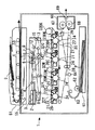
まず、図1にて、画像形成装置全体の構成・動作について説明する。
図1において、1は画像形成装置としてのカラー複写機の装置本体、2は入力画像情報に基づいたレーザ光を発する書込み部(露光部)、20Y、20M、20C、20BKは各色(イエロー、マゼンタ、シアン、ブラック)に対応したプロセスカートリッジ、21は各プロセスカートリッジ20Y、20M、20C、20BKにそれぞれ収容された像担持体としての感光体ドラム、22は感光体ドラム21上を帯電する帯電部、23Y、23M、23C、23BKは感光体ドラム21上に形成される静電潜像を現像する現像装置(現像部)、24は感光体ドラム21上に形成されたトナー像を中間転写ベルト27に転写する転写バイアスローラ、25は感光体ドラム21上の未転写トナーを回収するクリーニング装置(クリーニング部)、を示す。
Embodiment 1 FIG.
A first embodiment of the present invention will be described in detail with reference to FIGS.
First, the configuration and operation of the entire image forming apparatus will be described with reference to FIG.
In FIG. 1, 1 is an apparatus main body of a color copying machine as an image forming apparatus, 2 is a writing section (exposure section) that emits laser light based on input image information, and 20Y, 20M, 20C, and 20BK are colors (yellow, magenta). , Cyan, and black), 21 is a photosensitive drum as an image carrier accommodated in each of the
また、27は複数色のトナー像が重ねて転写される像担持体としての中間転写ベルト、28は中間転写ベルト27上に形成されたトナー像を記録媒体Pに転写する第2転写バイアスローラ、29は中間転写ベルト27上の未転写トナーを回収する中間転写ベルトクリーニング装置、30は4色カラーのトナー像が転写された記録媒体Pを搬送する搬送ベルト、32Y、32M、32C、32BKは各現像装置23Y、23M、23C、23BKに各色のトナーを補給するトナー補給部、51は原稿Dを原稿読込部55に搬送する原稿搬送部、55は原稿Dの画像情報を読み込む原稿読込部、61は転写紙等の記録媒体Pが収納される給紙部、66は記録媒体P上の未定着画像を定着する定着部、を示す。
ここで、各プロセスカートリッジ20Y、20M、20C、20BKは、それぞれ、感光体ドラム21、帯電部22、クリーニング装置25、潤滑剤供給装置45(図2を参照できる。)が、一体化されたものである。そして、各プロセスカートリッジ20Y、20M、20C、20BKは、装置本体1に対して所定の交換サイクルにて交換される。同様に、各現像装置23Y、23M、23C、23BKも、装置本体1に対して所定の交換サイクルにて交換される。
各プロセスカートリッジ20Y、20M、20C、20BKにおける感光体ドラム21上では、それぞれ、各色(イエロー、マゼンタ、シアン、ブラック)の画像形成がおこなわれる。
Here, each of the
Image formation of each color (yellow, magenta, cyan, black) is performed on the
以下、画像形成装置における、通常のカラー画像形成時の動作について説明する。
まず、原稿Dは、原稿搬送部51の搬送ローラによって、原稿台から図中の矢印方向に搬送されて、原稿読込部55のコンタクトガラス53上に載置される。そして、原稿読込部55で、コンタクトガラス53上に載置された原稿Dの画像情報が光学的に読み取られる。
Hereinafter, an operation during normal color image formation in the image forming apparatus will be described.
First, the document D is transported from the document table in the direction of the arrow in the drawing by the transport roller of the
詳しくは、原稿読込部55は、コンタクトガラス53上の原稿Dの画像に対して、照明ランプから発した光を照射しながら走査させる。そして、原稿Dにて反射した光を、ミラー群及びレンズを介して、カラーセンサに結像する。原稿Dのカラー画像情報は、カラーセンサにてRGB(レッド、グリーン、ブルー)の色分解光ごとに読み取られた後に、電気的な画像信号に変換される。さらに、RGBの色分解画像信号をもとにして画像処理部(不図示である。)で色変換処理、色補正処理、空間周波数補正処理等の処理をおこない、イエロー、マゼンタ、シアン、ブラックのカラー画像情報を得る。
Specifically, the
そして、イエロー、マゼンタ、シアン、ブラックの各色の画像情報は、書込み部2に送信される。そして、書込み部2からは、各色の画像情報に基づいたレーザ光(露光光)が、それぞれ、対応するプロセスカートリッジ20Y、20M、20C、20BKの感光体ドラム21上に向けて発せられる。
Then, the image information of each color of yellow, magenta, cyan, and black is transmitted to the
一方、4つの感光体ドラム21は、それぞれ、図1の時計方向に回転している。そして、まず、感光体ドラム21の表面は、帯電部22との対向位置で、一様に帯電される(帯電工程である。)。こうして、感光体ドラム21上には、帯電電位が形成される。その後、帯電された感光体ドラム21表面は、それぞれのレーザ光の照射位置に達する。
書込み部2において、光源から画像信号に対応したレーザ光が各色に対応して射出される。レーザ光は、ポリゴンミラー3に入射して反射した後に、レンズ4、5を透過する。レンズ4、5を透過した後のレーザ光は、イエロー、マゼンタ、シアン、ブラックの色成分ごとに別の光路を通過することになる(露光工程である。)。
On the other hand, the four
In the
イエロー成分に対応したレーザ光は、ミラー6〜8で反射された後に、紙面左側から1番目のプロセスカートリッジ20Yの感光体ドラム21表面に照射される。このとき、イエロー成分のレーザ光は、高速回転するポリゴンミラー3により、感光体ドラム21の回転軸方向(主走査方向)に走査される。こうして、帯電部22にて帯電された後の感光体ドラム21上には、イエロー成分に対応した静電潜像が形成される。
The laser beam corresponding to the yellow component is reflected by the mirrors 6 to 8 and then irradiated onto the surface of the
同様に、マゼンタ成分に対応したレーザ光は、ミラー9〜11で反射された後に、紙面左から2番目のプロセスカートリッジ20Mの感光体ドラム21表面に照射されて、マゼンタ成分に対応した静電潜像が形成される。シアン成分のレーザ光は、ミラー12〜14で反射された後に、紙面左から3番目のプロセスカートリッジ20Cの感光体ドラム212表面に照射されて、シアン成分の静電潜像が形成される。ブラック成分のレーザ光は、ミラー15で反射された後に、紙面左から4番目のプロセスカートリッジ20BKの感光体ドラム21表面に照射されて、ブラック成分の静電潜像が形成される。
Similarly, the laser beam corresponding to the magenta component is reflected by the mirrors 9 to 11 and then irradiated to the surface of the
その後、各色の静電潜像が形成された感光体ドラム21表面は、それぞれ、現像装置23Y、23M、23C、23BKとの対向位置に達する。そして、各現像装置23Y、23M、23C、23BKから感光体ドラム21上に各色のトナーが供給されて、感光体ドラム21上の潜像が現像される(現像工程である。)。
その後、現像工程後の感光体ドラム21表面は、それぞれ、フォトセンサ41(図2を参照できる。)との対向位置を通過した後に、中間転写ベルト27との対向位置に達する。ここで、それぞれの対向位置には、中間転写ベルト27の内周面に当接するように転写バイアスローラ24が設置されている。そして、転写バイアスローラ24の位置で、中間転写ベルト27上に、感光体ドラム21上に形成された各色の画像が、順次重ねて転写される(第1転写工程である。)。
Thereafter, the surface of the
Thereafter, the surface of the
そして、第1転写工程後の感光体ドラム21表面は、それぞれ、クリーニング装置25との対向位置に達する。そして、クリーニング装置25で、感光体ドラム21上に残存する未転写トナーが回収される(クリーニング工程である。)。
その後、感光体ドラム21表面は、不図示の除電部を通過して、感光体ドラム21における一連の作像プロセスが終了する。
Then, the surface of the
Thereafter, the surface of the
他方、感光体ドラム21上の各色の画像が重ねて転写された中間転写ベルト27(像担持体)表面は、図中の矢印方向に走行して、第2転写バイアスローラ28の位置に達する。そして、第2転写バイアスローラ28の位置で、記録媒体P上に中間転写ベルト27上のフルカラーの画像が2次転写される(第2転写工程である。)。
その後、中間転写ベルト27表面は、中間転写ベルトクリーニング部29の位置に達する。そして、中間転写ベルト27上の未転写トナーが中間転写ベルトクリーニング装置29に回収されて、中間転写ベルト27上の一連の転写プロセスが完了する。
On the other hand, the surface of the intermediate transfer belt 27 (image carrier) on which the images of the respective colors on the
Thereafter, the surface of the
ここで、第2転写バイアスローラ28位置の記録媒体Pは、給紙部61から搬送ガイド63、レジストローラ64等を経由して搬送されたものである。
詳しくは、記録媒体Pを収納する給紙部61から、給紙ローラ62により給送された転写紙Pが、搬送ガイド63を通過した後に、レジストローラ64に導かれる。レジストローラ64に達した記録媒体Pは、中間転写ベルト27上のトナー像とタイミングを合わせて、第2転写バイアスローラ28の位置に向けて搬送される。
Here, the recording medium P at the position of the second transfer bias roller 28 is transported from the
Specifically, the transfer paper P fed by the
その後、フルカラー画像が転写された記録媒体Pは、搬送ベルト30により、定着部66に導かれる。定着部66では、加熱ローラ67と加圧ローラ68とのニップにて、カラー画像が記録媒体P上に定着される。
そして、定着工程後の記録媒体Pは、排紙ローラ69によって、装置本体1外に出力画像として排出されて、一連の画像形成プロセスが完了する。
Thereafter, the recording medium P on which the full-color image is transferred is guided to the fixing
Then, the recording medium P after the fixing process is discharged as an output image by the
次に、図2にて、画像形成装置の作像部について詳述する。
図2は作像部を示す断面図である。なお、装置本体1に設置される4つの作像部は、作像プロセスに用いられるトナーTの色が異なる以外はほぼ同一構造であるので、プロセスカートリッジ及び現像装置及びトナー補給部における符号のアルファベット(Y、M、C、BK)を省略して図示する。
図2に示すように、プロセスカートリッジ20には、像担持体としての感光体ドラム21と、帯電部22と、クリーニング装置25と、潤滑剤供給装置45と、がケース26に一体的に収納されている。
Next, the image forming unit of the image forming apparatus will be described in detail with reference to FIG.
FIG. 2 is a cross-sectional view showing the image forming unit. The four image forming units installed in the apparatus main body 1 have substantially the same structure except that the color of the toner T used in the image forming process is different. Therefore, the alphabet of reference numerals in the process cartridge, the developing device, and the toner replenishing unit. (Y, M, C, BK) is omitted for illustration.
As shown in FIG. 2, in the
ここで、像担持体としての感光体ドラム21は、負帯電性の有機感光体であって、ドラム状導電性支持体上に感光層等を設けたものである。
図示は省略するが、感光体ドラム21は、基層としての導電性支持体上に、絶縁層である下引き層、感光層としての電荷発生層及び電荷輸送層、保護層(表面層)が順次積層されている。
感光体ドラム21の導電性支持体(基層)としては、体積抵抗が1010Ωcm以下の導電性材料を用いることができる。
Here, the
Although not shown, the
As the conductive support (base layer) of the
感光体ドラム21の感光層は、積層構造とすることもできるし、単層構造とすることもできる。
まず、感光層を電荷発生層と電荷輸送層とからなる積層構造とした場合について説明する。
電荷発生層は、電荷発生物質を主成分とする層である。電荷発生層には公知の電荷発生物質を用いることができる。具体的には、電荷発生物質として、モノアゾ顔料、ジスアゾ顔料、トリスアゾ顔料、ペリレン系顔料、ペリノン系顔料、キナクリドン系顔料、キノン系縮合多環化合物、スクアリック酸系染料、他のフタロシアニン系顔料、ナフタロシアニン系顔料、アズレニウム塩系染料等を用いることができる。これらの電荷発生物質は単独でも、2種以上混合して用いることもできる。
電荷発生層は、電荷発生物質を必要に応じて結着樹脂とともに適当な溶剤中にボールミル、アトライター、サンドミル、超音波等を用いて分散して、これを導電性支持体上(又は、下引き層上)に塗布して、乾燥することにより形成される。塗布液の塗工法としては、浸漬塗工法、スプレーコート、ビートコート、ノズルコート、スピナーコート、リングコート等の方法を用いることができる。電荷発生層の膜厚は、0.01〜5μm程度が適当である(さらに、好ましくは0.1〜2μm程度である。)。
The photosensitive layer of the
First, a case where the photosensitive layer has a laminated structure including a charge generation layer and a charge transport layer will be described.
The charge generation layer is a layer mainly composed of a charge generation material. A known charge generation material can be used for the charge generation layer. Specifically, as a charge generating substance, monoazo pigment, disazo pigment, trisazo pigment, perylene pigment, perinone pigment, quinacridone pigment, quinone condensed polycyclic compound, squalic acid dye, other phthalocyanine pigment, na A phthalocyanine pigment, an azulenium salt dye, or the like can be used. These charge generation materials can be used alone or in combination of two or more.
In the charge generation layer, the charge generation material is dispersed in a suitable solvent together with a binder resin as necessary using a ball mill, attritor, sand mill, ultrasonic wave, etc., and this is dispersed on the conductive support (or below). It is formed by applying on the pulling layer and drying. As a coating method for the coating solution, a dip coating method, spray coating, beat coating, nozzle coating, spinner coating, ring coating, or the like can be used. The thickness of the charge generation layer is suitably about 0.01 to 5 μm (more preferably about 0.1 to 2 μm).
電荷輸送層は、電荷輸送物質及び結着樹脂を適当な溶剤に溶解又は分散して、これを電荷発生層上に塗布、乾燥することにより形成できる。また、必要により単独又は2種以上の可塑剤、レベリング剤、酸化防止剤等を添加することもできる。電荷輸送物質の量は、結着樹脂100重量部に対して、20〜300重量部(好ましくは、40〜150重量部である。)が適当である。また、電荷輸送層の膜厚は解像度・応答性の点から25μm以下にすることが好ましい。下限値に関しては、作像プロセス(特に、帯電電位等である。)によって異なるが、5μm以上が好ましい。 The charge transport layer can be formed by dissolving or dispersing the charge transport material and the binder resin in a suitable solvent, and applying and drying the solution on the charge generation layer. If necessary, one or more plasticizers, leveling agents, antioxidants and the like can be added. The amount of the charge transport material is suitably 20 to 300 parts by weight (preferably 40 to 150 parts by weight) with respect to 100 parts by weight of the binder resin. The thickness of the charge transport layer is preferably 25 μm or less from the viewpoint of resolution and responsiveness. The lower limit varies depending on the image forming process (particularly, charging potential), but is preferably 5 μm or more.
次に、感光層を単層構造とした場合について説明する。
単層構造の感光層は、上述の電荷発生物質、電荷輸送物質、結着樹脂等を適当な溶剤に溶解又は分散して、これを導電性支持体上(又は、下引き層上)に塗布、乾燥することによって形成できる。電荷輸送物質を含有させずに、電荷発生物質と結着樹脂とから構成してもよい。また、必要により可塑剤やレベリング剤、酸化防止剤等を添加することもできる。
結着樹脂としては上述の電荷輸送層の形成時に用いる結着樹脂の他に、上述の電荷発生層の形成時に用いる結着樹脂を混合して用いてもよい。さらには、高分子電荷輸送物質も良好に使用できる。結着樹脂100重量部に対する電荷発生物質の量は5〜40重量部が好ましく、電荷輸送物質の量は0〜190重量部が好ましい(さらに好ましくは50〜150重量部である。)。
単層構造の感光層は、電荷発生物質、結着樹脂を電荷輸送物質とともにテトラヒドロフラン、ジオキサン、ジクロロエタン、シクロヘキサン等の溶媒を用いて分散機等で分散した塗工液を、浸漬塗工法やスプレーコート、ビードコート、リングコート等で塗工して形成できる。感光層の膜厚は、5〜25μm程度が適当である。
Next, a case where the photosensitive layer has a single layer structure will be described.
The photosensitive layer having a single-layer structure is obtained by dissolving or dispersing the above-described charge generating substance, charge transporting substance, binder resin, etc. in an appropriate solvent and coating it on a conductive support (or undercoat layer). It can be formed by drying. You may comprise from a charge generation material and binder resin, without containing a charge transport material. Moreover, a plasticizer, a leveling agent, antioxidant, etc. can also be added as needed.
As the binder resin, in addition to the binder resin used when the charge transport layer is formed, a binder resin used when the charge generation layer is formed may be mixed and used. Furthermore, polymer charge transport materials can also be used favorably. The amount of the charge generating material is preferably 5 to 40 parts by weight with respect to 100 parts by weight of the binder resin, and the amount of the charge transporting material is preferably 0 to 190 parts by weight (more preferably 50 to 150 parts by weight).
The photosensitive layer with a single-layer structure is a dip coating method or spray coating method in which a coating solution in which a charge generating material and a binder resin are dispersed together with a charge transporting material using a solvent such as tetrahydrofuran, dioxane, dichloroethane, and cyclohexane by a dispersing machine. It can be formed by coating with bead coat, ring coat or the like. The film thickness of the photosensitive layer is suitably about 5 to 25 μm.
感光体ドラム21の下引き層は、一般には樹脂を主成分とするが、これらの樹脂の上に感光層を溶剤で塗布することを考えると、一般の有機溶剤に対して耐溶剤性の高い樹脂であることが望ましい。このような樹脂としては、ポリビニルアルコール、カゼイン、ポリアクリル酸ナトリウム等の水溶性樹脂、共重合ナイロン、メトキシメチル化ナイロン等のアルコール可溶性樹脂、ポリウレタン、メラミン樹脂、フェノール樹脂、アルキッド−メラミン樹脂、エポキシ樹脂等、三次元網目構造を形成する硬化型樹脂等が挙げられる。下引き層には、モアレ防止、残留電位の低減等のために、酸化チタン、シリカ、アルミナ、酸化ジルコニウム、酸化スズ、酸化インジウム等の金属酸化物の微粉末顔料を加えてもよい。また、これらの下引き層は、上述した感光層と同様に、適当な溶媒及び塗工法を用いて形成することができる。下引き層の膜厚は、0〜5μm程度が適当である。
The undercoat layer of the
感光体ドラム21の保護層は、感光体ドラム21表面における機械的磨耗を軽減するためのものである。
本実施の形態1における保護層は、架橋構造を有するバインダー樹脂で形成されている。架橋構造は、1分子内に複数個の架橋性官能基を有する反応性モノマーを使用して、光や熱エネルギーを用いて架橋反応を生じさせることで形成される3次元の網目構造である。この網目構造を有するバインダー樹脂は、高い耐摩耗性を発揮することになる。さらに、本実施の形態1では、電気的な安定性、耐刷性、寿命の観点から、上述の反応性モノマーとして、全部又は一部に電荷輸送能を有するモノマーを使用している。このようなモノマーを使用することにより、網目構造中に電荷輸送部位が形成されて、保護層としての機能も充分に発揮される。
The protective layer of the
The protective layer in the first embodiment is formed of a binder resin having a crosslinked structure. The crosslinked structure is a three-dimensional network structure formed by using a reactive monomer having a plurality of crosslinking functional groups in one molecule and causing a crosslinking reaction using light or thermal energy. The binder resin having this network structure exhibits high wear resistance. Furthermore, in the first embodiment, from the viewpoint of electrical stability, printing durability, and lifetime, a monomer having a charge transporting ability is used as the above-mentioned reactive monomer in whole or in part. By using such a monomer, a charge transport site is formed in the network structure, and the function as a protective layer is sufficiently exhibited.
電荷輸送能を有する反応性モノマーとしては、同一分子中に電荷輸送性成分と加水分解性の置換基を有する珪素原子とをそれぞれ少なくとも1つ以上含有する化合物、同一分子中に電荷輸送性成分とヒドロキシル基とを含有する化合物、同一分子中に電荷輸送性成分とカルボキシル基とを含有する化合物、同一分子中に電荷輸送性成分とエポキシ基とを含有する化合物、同一分子中に電荷輸送性成分とイソシアネート基とを含有する化合物等を用いることができる。これら反応性基を有する電荷輸送性材料は、単独で用いてもよいし、2種以上併用してもよい。
また、電荷輸送能を有するモノマーとして、電気的・化学的安定性が高いこと、キャリアの移動度が速いこと等から、トリアリールアミン構造を有する反応性モノマーを用いることもできる。
さらに、塗工時の粘度調整、架橋型電荷輸送層の応力緩和、低表面エネルギー化や摩擦係数低減等の機能付与のために、1官能及び2官能の重合性モノマー及び重合性オリゴマーを併用することもできる。これらの重合性モノマー、オリゴマーとしては、公知のものが利用できる。
Examples of the reactive monomer having charge transporting ability include a compound containing at least one charge transporting component and a silicon atom having a hydrolyzable substituent in the same molecule, and a charge transporting component in the same molecule. A compound containing a hydroxyl group, a compound containing a charge transporting component and a carboxyl group in the same molecule, a compound containing a charge transporting component and an epoxy group in the same molecule, a charge transporting component in the same molecule And a compound containing an isocyanate group can be used. These charge transport materials having a reactive group may be used alone or in combination of two or more.
A reactive monomer having a triarylamine structure can also be used as the monomer having a charge transporting ability because of its high electrical and chemical stability and high carrier mobility.
In addition, monofunctional and bifunctional polymerizable monomers and polymerizable oligomers are used in combination for viscosity adjustment during coating, stress relaxation of the cross-linked charge transport layer, low surface energy, friction coefficient reduction, and other functions. You can also. As these polymerizable monomers and oligomers, known ones can be used.
保護層は、熱又は光を用いて正孔輸送性化合物の重合又は架橋をおこなって形成される。熱により重合反応を行う際には、熱エネルギーのみで重合反応が進行する場合と重合開始剤が必要となる場合とがあるが、より低い温度で効率よく反応を進行させるためには、開始剤を添加することが好ましい。光により重合させる場合は、光として紫外線を用いることが好ましいが、光エネルギーのみで反応が進行することはごく稀であり、一般には光重合開始剤が併用される。この場合の重合開始剤とは、主には波長400nm以下の紫外線を吸収してラジカルやイオン等の活性種を生成して、重合を開始させるものである。なお、上述した熱及び光重合開始剤を併用することも可能である。 The protective layer is formed by polymerizing or crosslinking the hole transporting compound using heat or light. When performing the polymerization reaction by heat, there are cases where the polymerization reaction proceeds only with thermal energy and a polymerization initiator is required, but in order to advance the reaction efficiently at a lower temperature, the initiator Is preferably added. In the case of polymerization by light, it is preferable to use ultraviolet light as light, but the reaction rarely proceeds only by light energy, and a photopolymerization initiator is generally used in combination. The polymerization initiator in this case mainly absorbs ultraviolet rays having a wavelength of 400 nm or less, generates active species such as radicals and ions, and initiates polymerization. In addition, it is also possible to use together the heat | fever and photoinitiator mentioned above.
このように形成した網目構造を有する保護層は、耐摩耗性が高い反面、架橋反応時に体積収縮が大きく、あまり厚膜化するとクラックなどを生じる場合がある。このような場合には、保護層を積層構造として、下層(感光層側)には低分子分散ポリマーからなる保護層を形成して、上層(表面側)には架橋構造を有する保護層を形成しても良い。
以上述べたように、本実施の形態1では、感光体ドラム21の表面に、架橋構造を有するとともに電荷郵輸送材を分散してなるバインダー樹脂で形成された硬い保護層を設けているために、感光体ドラム21としての機能を損なわずに、クリーニングブレード25a、クリーニングブラシ25b等による感光体膜削れを防止することができる。
The protective layer having a network structure formed in this manner has high wear resistance, but has a large volume shrinkage during the crosslinking reaction, and may become cracked if it is too thick. In such a case, the protective layer has a laminated structure, a protective layer made of a low molecular weight dispersion polymer is formed on the lower layer (photosensitive layer side), and a protective layer having a crosslinked structure is formed on the upper layer (surface side). You may do it.
As described above, in the first embodiment, the surface of the
図2を参照して、帯電部22は、導電性芯金の外周に中抵抗の弾性層を被覆してなる帯電ローラである。帯電ローラ22には不図示の電源部から所定の電圧が印加されて、これにより対向する感光体ドラム21の表面を一様に帯電する。
Referring to FIG. 2, the charging
現像装置(現像部)23は、主として、感光体ドラム21に対向する現像ローラ23aと、現像ローラ23aに対向する第1搬送スクリュ23bと、仕切部材23eを介して第1搬送スクリュ23bに対向する第2搬送スクリュ23cと、現像ローラ23aに対向するドクターブレード23dと、で構成される。現像ローラ23aは、内部に固設されてローラ周面に磁極を形成するマグネットと、マグネットの周囲を回転するスリーブと、で構成される。マグネットによって現像ローラ23a(スリーブ)上に複数の磁極が形成されて、現像ローラ23a上に現像剤Gが担持されることになる。
The developing device (developing unit) 23 mainly faces the first conveying
現像装置23内には、キャリアCとトナーTとからなる2成分現像剤Gが収容されている。
トナーTは、画質向上のために、円形度が0.98以上の球形トナーを使用している。「円形度」は、フロー式粒子像分析装置「FPIA−2000」(東亜医用電子社製)により計測した平均円形度である。具体的には、容器中の予め不純固形物を除去した水100〜150ml中に、分散剤として界面活性剤(好ましくは、アルキルベンゼンスルホン酸塩である。)を0.1〜0.5ml加えて、さらに測定試料(トナー)を0.1〜0.5g程度加える。その後、このトナーが分散した懸濁液を、超音波分散器で約1〜3分間分散処理して、分散液濃度が3000〜10000個/μlとなるようにしたものを上述の分析装置にセットして、トナーの形状及び分布を測定する。
In the developing
As the toner T, a spherical toner having a circularity of 0.98 or more is used to improve the image quality. The “circularity” is an average circularity measured by a flow type particle image analyzer “FPIA-2000” (manufactured by Toa Medical Electronics Co., Ltd.). Specifically, 0.1 to 0.5 ml of a surfactant (preferably an alkylbenzene sulfonate) is added as a dispersant to 100 to 150 ml of water from which impure solids have been removed in advance. Further, about 0.1 to 0.5 g of a measurement sample (toner) is added. Thereafter, the suspension in which the toner is dispersed is subjected to a dispersion treatment with an ultrasonic disperser for about 1 to 3 minutes, and the dispersion liquid concentration is set to 3000 to 10000 / μl in the above-described analyzer. Then, the shape and distribution of the toner are measured.
球形トナーとしては、従来から広く用いられている粉砕法によって形状が歪な異形のトナー(粉砕トナー)を加熱処理等して球形化したものや、重合法により製造されたもの等を用いることができる。
このような球形トナーを用いる場合、従来は、クリーニングブレード25aと感光体ドラム21との僅かな隙間に入り込んでやがてその隙間をすり抜けてクリーニング不良が生じることがあった。しかし、本実施の形態1では、潤滑剤供給装置45によって潤滑剤を感光体ドラム21表面に塗布して、感光体ドラム21上におけるトナー剥離性(除去性)を向上させるために、クリーニング不良の発生が抑止される。
As the spherical toner, it is possible to use an irregularly shaped toner (pulverized toner) whose shape is distorted by a pulverization method that has been widely used so far, which is spheroidized by heat treatment or the like, or a toner manufactured by a polymerization method. it can.
When such a spherical toner is used, conventionally, there is a case where a slight gap between the
クリーニング装置25は、感光体ドラム21に当接して感光体ドラム21表面をクリーニングするクリーニングブレード25a、感光体ドラム21に摺接するクリーニングブラシ25b、等で構成される。
クリーニングブレード25aは、ウレタンゴム等のゴム材料からなり、感光体ドラム21表面に所定角度かつ所定圧力で当接している。これにより、感光体ドラム21上に付着する未転写トナー等の付着物が機械的に掻き取られてクリーニング装置25内に回収されることになる。
The
The
クリーニングブラシ25bは、芯金の外周にブラシ毛を巻装したものであって、そのブラシ毛が感光体ドラム21表面に当接した状態で、図2の時計方向に回転する。そして、感光体ドラム21上に付着する未転写トナー等の付着物は、クリーニングブラシ25bに掻き取られた後に、クリーニング装置25内に回収される。ここで、感光体ドラム21上に付着する付着物としては、未転写トナーの他に、記録媒体P(用紙)から生じる紙粉、帯電部22による放電時に感光体ドラム21上に生じる放電生成物、トナーに添加されている添加剤、等がある。
The cleaning
潤滑剤供給装置45は、感光体ドラム21に摺接するブラシ毛が周設されて感光体ドラム21上に潤滑剤を供給するブラシ状回転部材としての塗布ブラシ45b、塗布ブラシ45bに当接する固形潤滑剤45c、固形潤滑剤45cを塗布ブラシ45bに向けて付勢する圧縮スプリング45d、感光体ドラム21に当接して感光体ドラム21上に供給された潤滑剤を薄層化する塗布ブレード45a(薄層化ブレード)、潤滑剤の飛散を規制する規制部材45e、等で構成される。潤滑剤供給装置45は、クリーニング装置25(クリーニングブレード25a)に対して感光体ドラム21の回転方向下流側(走行方向下流側)であって、帯電部22に対して感光体ドラム21の回転方向上流側に配設されている。
The
図3及び図4を参照して、ブラシ状回転部材としての塗布ブラシ45b(供給ブラシ)は、芯金の外周にブラシ毛を巻装したものであって、そのブラシ毛が感光体ドラム21表面に当接した状態で、図2の反時計方向に回転する。これにより、固形潤滑剤45から塗布ブラシ45bを介して感光体ドラム21上に潤滑剤が供給される。
Referring to FIGS. 3 and 4, an
塗布ブラシ45bは、長さ(毛足)が0.2〜20mm(好ましくは、0.5〜10mm)の範囲のブラシ毛が基布上に植毛されたものを芯金上にスパイラル状に巻き付けたものである。ブラシ毛の長さが20mmを超えると、経時における感光体ドラム21との繰り返し摺擦によって、ブラシ毛が所定方向に倒毛して、固形潤滑剤45の掻取性や感光体ドラム21への潤滑剤供給性が低下してしまう。これに対して、ブラシ毛の長さが0.2mm未満であると、固形潤滑剤45cや感光体ドラム21に対する物理的な当接力が不足してしまう。したがって、ブラシ毛の長さは上述の範囲であることが好ましい。
塗布ブラシ45bのブラシ毛としては、ナイロン、レーヨン、アクリル、ビニロン、ポリエステル、塩化ビニル等の樹脂繊維を用いることができ、必要に応じてカーボン等の導電付与剤が混入された導電繊維を用いることができる。また、ブラシ毛は、ブラシ密度が1〜50万本/inch2、ブラシ抵抗が10-2〜1012Ω・cmのものを用いることが好ましい。
本実施の形態1における塗布ブラシ45bのブラシ毛は、ブラシの長さが3mm、ブラシ密度が10万本/inch2、ブラシ抵抗が105Ω・cmに設定されている。
The
As the bristles of the
The brush bristles of the
塗布ブラシ45bは、図2の時計方向に回転する感光体ドラム21に対して順方向で接触するように回転する(図2の反時計方向の回転である。)。すなわち、塗布ブラシ45bの回転方向は、感光体ドラム21との摺接位置において、感光体ドラム21の回転方向(走行方向)と同方向になるように構成されている。
また、塗布ブラシ45bは、固形潤滑剤45cと感光体ドラム21とに摺接するように配置されていて、塗布ブラシ45bが回転することによって固形潤滑剤45cから潤滑剤を掻き取り、その潤滑剤を感光体ドラム21上に塗布する。また、塗布ブラシ45bの回転方向下流側であって摺接位置(塗布ブラシ45bが感光体ドラム21に摺接する位置である。)の近傍には、規制部材45eが設置されている。なお、潤滑剤が感光体ドラム21上に供給されるメカニズムと規制部材45eとについては、後で詳しく説明する。
固形潤滑剤45cの後方部には、塗布ブラシ45bと固形潤滑剤45との接触ムラをなくすために圧縮スプリング45dが配置されていて、固形潤滑剤45cを塗布ブラシ45bに付勢している。
The
The
A
本実施の形態1では、固形潤滑剤45cをステアリン酸亜鉛で形成している。詳しくは、固形潤滑剤45cは、ステアリン酸亜鉛を主成分とする潤滑油添加剤を溶解したもので、塗りすぎによる副作用がなく、充分な潤滑性があるものが好適である。
ステアリン酸亜鉛は、代表的なラメラ結晶紛体である。ラメラ結晶は両親媒性分子が自己組織化した層状構造を有していて、せん断力が加わると層間にそって結晶が割れて滑りやすい。したがって、感光体ドラム21表面を低摩擦係化することができる。すなわち、せん断力を受けて均一に感光体ドラム21表面を覆っていくラメラ結晶によって、少量の潤滑剤によって効果的に感光体ドラム21表面を覆うことができる。
In the first embodiment, the
Zinc stearate is a typical lamellar crystal powder. A lamellar crystal has a layered structure in which amphiphilic molecules are self-organized, and when a shearing force is applied, the crystal breaks along the layers and is slippery. Therefore, the surface of the
なお、固形潤滑剤45cとしては、ステアリン酸亜鉛の他にも、ステアリン酸バリウム、ステアリン酸鉄、ステアリン酸ニッケル、ステアリン酸コバルト、ステアリン酸銅、ステアリン酸ストロンチュウム、ステアリン酸カルシウム等のステアリン酸基を有するものを用いることができる。また、同じ脂肪酸基であるオレイン酸亜鉛、オレイン酸バリウム、オレイン酸鉛、以下、ステアリン酸と同様の化合物や、パルチミン酸亜鉛、パルチミン酸バリウム、パルチミン酸鉛、以下、ステアリン酸と同様の化合物を使用して良い。他にも、脂肪酸基として、カプリル酸、リノレン酸、コリノレン酸等を使用することができる。さらに、カンデリラワックス、カンルナウバワックス、ライスワックス、木ろう、おおば油、みつろう、ラノリン等のワックスを使用することもできる。これらは有機系の固形潤滑剤となりやすく、トナーとの相性が良い。
As the
塗布ブレード45aは、ウレタンゴム等のゴム材料からなるブレード状部材であって、感光体ドラム21表面に所定角度かつ所定圧力で当接している。塗布ブレード45aは、クリーニングブレード25aに対して、感光体ドラム21の回転方向下流側(走行方向下流側)に配設されている。そして、塗布ブラシ45bによって感光体ドラム21上に供給された潤滑剤は、塗布ブレード45aによって、感光体ドラム21上に均一かつ適量に薄層化される。
固形潤滑剤45cを塗布ブラシ45bを介して感光体ドラム21表面に塗布すると、感光体ドラム21表面には粉体状の潤滑剤が塗布されるが、この状態のままでは潤滑性は充分に発揮されないため、塗布ブレード45aが潤滑剤を薄層化・均一化する部材として機能することになる。塗布ブレード45aにより、感光体ドラム21上での潤滑剤の皮膜化がおこなわれて、潤滑剤はその潤滑性を充分に発揮することになる。
The
When the
このように、本実施の形態1では、クリーニングブレード25aと塗布ブレード45a(薄層化手段)とを別々に設けているために、クリーニング性と潤滑剤塗布性とを良好に維持することができるとともに、感光体ドラム21への潤滑剤供給によって双方のブレード25a、45aの磨耗・劣化を軽減することができる。
なお、本実施の形態1において、クリーニングブレード25aと塗布ブレード45aとを、それぞれ感光体ドラム21に対して接離自在に構成することもできる。これにより、経時において双方のブレード25a、45aが塑性変形してしまって双方のブレード25a、45aの機能が低下するという不具合が生じるのを抑止することができる。さらに、画像形成装置の高速化にともない感光体ドラム21の移動速度(回転速度)が高速化した場合であっても、双方のブレード25a、45aの耐久性が低下するという不具合が生じるのを抑止することができる。
As described above, in the first embodiment, since the
In the first embodiment, the
図2にて、先に述べた作像プロセスをさらに詳しく説明する。
現像ローラ23aは、図2中の矢印方向に回転している。現像装置23内の現像剤Gは、間に仕切部材23eを介在するように配設された第1搬送スクリュ23b及び第2搬送スクリュ23cの矢印方向の回転によって、トナー補給部32からトナー補給口23fを介して補給されたトナーTとともに撹拌混合されながら長手方向に循環する(図2の紙面垂直方向である。)。
The image forming process described above will be described in more detail with reference to FIG.
The developing
そして、摩擦帯電してキャリアCに吸着したトナーTは、キャリアCとともに現像ローラ23a上に担持される。現像ローラ23a上に担持された現像剤Gは、その後にドクターブレード23dの位置に達する。そして、現像ローラ23a上の現像剤Gは、ドクターブレード23dの位置で適量に調整された後に、感光体ドラム21との対向位置(現像領域である。)に達する。
Then, the toner T that is frictionally charged and adsorbed on the carrier C is carried on the developing
その後、現像領域において、現像剤G中のトナーTが、感光体ドラム21表面に形成された静電潜像に付着する。詳しくは、レーザ光Lが照射された画像部の潜像電位(露光電位)と、現像ローラ23aに印加された現像バイアスとの、電位差(現像ポテンシャル)によって形成される電界によって、トナーTが潜像に付着する。
Thereafter, in the development area, the toner T in the developer G adheres to the electrostatic latent image formed on the surface of the
その後、現像工程にて感光体ドラム21に付着したトナーTは、そのほとんどが中間転写ベルト27上に転写される。そして、感光体ドラム21上に残存した未転写のトナーTが、クリーニングブレード25a及びクリーニングブラシ25bによってクリーニング装置25内に回収される。その後、クリーニング工程後の感光体ドラム21表面は、潤滑剤供給装置45、除電部(除電光Hの照射位置)を順次通過して、一連の作像プロセスが終了する。
Thereafter, most of the toner T adhering to the
ここで、装置本体1に設けられたトナー補給部32は、交換自在に構成されたトナーボトル33と、トナーボトル33を保持・回転駆動するとともに現像装置23に新品トナーTを補給するトナーホッパ部34と、で構成されている。また、トナーボトル33内には、新品のトナーT(イエロー、マゼンタ、シアン、ブラックのいずれかである。)が収容されている。また、トナーボトル33の内周面には、螺旋状の突起が形成されている。
Here, a
なお、トナーボトル33内の新品トナーTは、現像装置23内のトナーT(既設のトナーである。)の消費にともない、トナー補給口23fから現像装置23内に適宜に補給されるものである。現像装置23内のトナーTの消費は、感光体ドラム21に対向する反射型フォトセンサ41と、現像装置23の第2搬送スクリュ23cの下方に設置された磁気センサ40と、によって間接的又は直接的に検知される。
The new toner T in the
ここで、本実施の形態1では、トナー濃度(TC)が所定の範囲内になるように制御されている。具体的には、磁気センサ40や反射型フォトセンサ41の検知結果が上述したトナー濃度(現像剤G中のトナーTの割合である。)の範囲に対応する出力値になるように、トナー補給部32からトナー補給口23fを介して現像装置23にトナーが補給される。
Here, in the first embodiment, the toner density (TC) is controlled to be within a predetermined range. Specifically, toner replenishment is performed so that the detection results of the
以下、本実施の形態1において特徴的な、規制部材45eの構成・動作について説明する。
まず、潤滑剤が担持された塗布ブラシ45b(ブラシ状回転部材)によって感光体ドラム21上に潤滑剤が供給されるメカニズムと、潤滑剤が飛散するメカニズムと、について説明する。
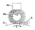
図5を参照して、矢印B方向に回転する塗布ブラシ45bは、固形潤滑剤45cに摺接して潤滑剤を削り取って、ブラシ毛中に潤滑剤Kを担持する。潤滑剤Kを担持した塗布ブラシ45bのブラシ毛は、感光体ドラム21との摺接位置(ニップ部)で、回転方向とは異なる方向に倒毛する。ここで、塗布ブラシ45bは、そのブラシ毛が感光体ドラム21との摺接位置で一定量食い込むように配設されていて、感光体ドラム21との間に所望のニップを形成している。
そして、回転方向とは異なる方向に倒毛したブラシ毛は、塗布ブラシ45bの回転に沿って摺接位置を通過した直後(感光体ドラム21との当接が開放された直後)に、その復元力によって矢印C方向に勢いよく変位する。この反発力によってブラシ毛に担持されていた潤滑剤Kが塗布ブラシ45bから離脱・飛翔して、矢印A方向に回転する感光体ドラム21上に付着(塗布)される。
Hereinafter, the configuration / operation of the regulating
First, a mechanism for supplying the lubricant onto the
Referring to FIG. 5,
Then, the bristles that fall in a direction different from the rotation direction are restored immediately after passing the sliding contact position along the rotation of the
ここで、摺接位置の近傍で塗布ブラシ45bから離脱・飛翔する潤滑剤K(図5の破線で囲んだ潤滑剤Kである。)は、そのすべてが感光体ドラム21上に供給されることはなく、その一部が感光体ドラム21以外の位置に向けて飛散してしまう。そして、潤滑剤供給装置45の外部にまで飛散した潤滑剤は、画像形成装置本体1内を汚染してしまうことになる。さらには、感光体ドラム21への潤滑剤の供給効率(供給量)を低下させてしまう。
このような潤滑剤の飛散は、塗布ブラシ45bによって固形潤滑剤45cから削り取られる潤滑剤の量が多くなって塗布ブラシ45b上に担持される潤滑剤の量が多くなってしまう場合や、摺接位置における塗布ブラシ45bのブラシ毛の倒れ量が大きくなって摺接位置を通過した直後のブラシ毛の反発力が大きくなってしまう場合、等に特に生じやすくなる。
Here, all of the lubricant K (lubricant K surrounded by a broken line in FIG. 5) that is separated from the
Such scattering of the lubricant may occur when the amount of lubricant scraped off from the
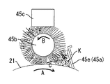
これに対して、本実施の形態1では、図4を参照して、規制部材45eを、塗布ブラシ45bの回転方向下流側であって摺接位置に近接させている。規制部材45eの幅方向(図4の紙面垂直方向である。)の長さは、塗布ブラシ45bの幅方向の長さと同等かそれ以上に設定されている。これによって、摺接位置の近傍で塗布ブラシ45bから離脱して感光体ドラム21以外の位置に向けて飛散する潤滑剤Kが規制されることになる。すなわち、感光体ドラム21以外の位置に向けて飛散しようとする潤滑剤Kは、規制部材45eによってその飛散の経路が遮断される。具体的に、感光体ドラム21以外の位置に向けて飛散しようとする潤滑剤Kは、規制部材45eに衝突して、その後に進路を変えて感光体ドラム21上に付着する。したがって、感光体ドラム21への潤滑剤Kの供給効率も向上することになる。
なお、本実施の形態1では規制部材45eを板状部材としたが、規制部材45eの形状はこれに限定されることなく、飛散する潤滑剤をせき止めて潤滑剤の進路を感光体ドラム21側に向けられるようなものであればよい。また、規制部材45eの材料としては、潤滑剤Kが付着しにくいものが好ましく、金属材料であっても樹脂材料であってもよい。
On the other hand, in the first embodiment, referring to FIG. 4, the regulating
In the first embodiment, the regulating
以上説明したように、本実施の形態1によれば、塗布ブラシ45b(ブラシ状回転部材)と感光体ドラム21(像担持体)との摺接位置の近傍であって塗布ブラシ45bの回転方向下流側に規制部材45eを設置しているために、潤滑剤Kの飛散を確実に抑止することができる。
As described above, according to the first embodiment, the rotation direction of the
なお、本実施の形態1では、クリーニング装置25及び潤滑剤供給装置45を、感光体ドラム21及び帯電部22と一体化してプロセスカートリッジ20を構成して、作像部のコンパクト化とメンテナンス作業性の向上とを図っている。
なお、クリーニング装置25や潤滑剤供給装置45を、プロセスカートリッジの構成部材とせずに、それぞれ単体で装置本体1に交換自在に設置されるように構成することもできる。さらには、クリーニング装置25と潤滑剤供給装置45とのみを、1つのユニット(クリーニング装置)として構成することもできる。その際、潤滑剤供給装置45をクリーニング装置25に内設して、塗布ブラシ45bとクリーニングブラシ25bとを共通化することもできる。これらのような場合にも、本実施の形態1と同様の効果を得ることができる。
また、本実施の形態1では、2成分現像剤を用いる2成分現像方式の現像装置23が搭載された画像形成装置に対して本発明を適用したが、1成分現像剤を用いる1成分現像方式の現像装置23が搭載された画像形成装置に対しても当然に本発明を適用することができる。
さらに、本実施の形態1では、像担持体としての感光体ドラム21に潤滑剤を供給する潤滑剤供給装置に対して本発明を適用したが、像担持体としての感光体ベルトに潤滑剤を供給する潤滑剤供給装置に対しても当然に本発明を適用することができる。さらには、本実施の形態1における像担持体としての中間転写ベルト27に潤滑剤を供給する潤滑剤供給装置に対しても当然に本発明を適用することができる。
In the first embodiment, the
In addition, the
In the first embodiment, the present invention is applied to the image forming apparatus equipped with the two-component developing
Further, in the first embodiment, the present invention is applied to the lubricant supply device that supplies the lubricant to the
実施の形態2.
図6にて、この発明の実施の形態2について詳細に説明する。
図6は、実施の形態2における潤滑剤供給装置の要部を示す概略図であって、前記実施の形態1における図4に相当する図である。本実施の形態2における潤滑剤供給装置は、規制部材45eが像担持体21に当接している点が、前記実施の形態1のものとは相違する。
A second embodiment of the present invention will be described in detail with reference to FIG.
FIG. 6 is a schematic view showing a main part of the lubricant supply device according to the second embodiment, and corresponds to FIG. 4 in the first embodiment. The lubricant supply device according to the second embodiment is different from that according to the first embodiment in that the regulating
図6を参照して、本実施の形態2における潤滑剤供給装置45も、前記実施の形態1のものと同様に、塗布ブラシ45bの回転方向が感光体ドラム21の回転方向とは逆になるように構成されている。また、本実施の形態2における潤滑剤供給装置45も、前記実施の形態1のものと同様に、塗布ブラシ45bと感光体ドラム21との摺接位置の近傍であって塗布ブラシ45bの回転方向下流側に規制部材45eが設置されている。
Referring to FIG. 6, in the
ここで、本実施の形態2では、前記実施の形態1とは異なり、規制部材45eが感光体ドラム21に所定角度かつ所定圧力で当接している。規制部材45eは、ウレタンゴム等のゴム材料からなるブレード状部材であって、塗布ブラシ45bによって感光体ドラム21上に供給された潤滑剤を薄層化する。すなわち、規制部材45eは、摺接位置近傍から飛散する潤滑剤を規制するとともに、前記実施の形態1における塗布ブレード45aの機能を果たすことになる。したがって、本実施の形態2の構成によれば、塗布ブレード45aを別に設置する必要がなくなって部品点数を軽減することができる。
Here, in the second embodiment, unlike the first embodiment, the regulating
以上説明したように、本実施の形態2によれば、前記実施の形態1と同様に、塗布ブラシ45b(ブラシ状回転部材)と感光体ドラム21(像担持体)との摺接位置の近傍であって塗布ブラシ45bの回転方向下流側に規制部材45eを設置しているために、潤滑剤Kの飛散を確実に抑止することができる。
As described above, according to the second embodiment, as in the first embodiment, the vicinity of the sliding contact position between the
実施の形態3.
図7にて、この発明の実施の形態3について詳細に説明する。
図7は、実施の形態3における潤滑剤供給装置の要部を示す概略図であって、前記実施の形態1における図4に相当する図である。本実施の形態3における潤滑剤供給装置は、導電性材料からなる規制部材45eに電圧が印加されている点が、前記実施の形態1のものとは相違する。
Embodiment 3 FIG.
A third embodiment of the present invention will be described in detail with reference to FIG.
FIG. 7 is a schematic diagram showing a main part of the lubricant supply device in the third embodiment, which corresponds to FIG. 4 in the first embodiment. The lubricant supply device according to the third embodiment is different from that according to the first embodiment in that a voltage is applied to a regulating
図7を参照して、本実施の形態3における潤滑剤供給装置45も、前記各実施の形態のものと同様に、塗布ブラシ45bと感光体ドラム21との摺接位置の近傍であって塗布ブラシ45bの回転方向下流側に規制部材45eが設置されている。
Referring to FIG. 7, the
ここで、本実施の形態3では、前記各実施の形態とは異なり、規制部材45eが導電性材料で形成されていて所定の電圧が印加されている。詳しくは、塗布ブラシ45bから感光体ドラム21に供給される潤滑剤Kは、感光体ドラム21やブラシ毛との摩擦によって帯電している。そして、その潤滑剤の帯電極性と同じ極性の電圧を、電源部70から導電性を有する規制部材45eに印加している。
これにより、規制部材45e上には飛翔した潤滑剤Kが静電的に付着しにくくなる。したがって、規制部材45e上への潤滑剤の堆積が軽減されて、感光体ドラム21上に供給される潤滑剤量が低下する不具合を抑止することができる。
Here, in the third embodiment, unlike the above-described embodiments, the regulating
As a result, the flying lubricant K is less likely to adhere electrostatically on the regulating
以上説明したように、本実施の形態3によれば、前記各実施の形態と同様に、塗布ブラシ45b(ブラシ状回転部材)と感光体ドラム21(像担持体)との摺接位置の近傍であって塗布ブラシ45bの回転方向下流側に規制部材45eを設置しているために、潤滑剤Kの飛散を確実に抑止することができる。
As described above, according to the third embodiment, as in each of the above embodiments, the vicinity of the sliding contact position between the
実施の形態4.
図8にて、この発明の実施の形態4について詳細に説明する。
図8は、実施の形態4における潤滑剤供給装置の要部を示す概略図であって、前記実施の形態1における図4に相当する図である。本実施の形態4における潤滑剤供給装置は、ブラシ状回転部材45bの回転方向が、前記実施の形態1のものとは相違する。
Embodiment 4 FIG.
A fourth embodiment of the present invention will be described in detail with reference to FIG.
FIG. 8 is a schematic view showing a main part of the lubricant supply device in the fourth embodiment, and corresponds to FIG. 4 in the first embodiment. In the lubricant supply device in the fourth embodiment, the rotation direction of the brush-like rotating
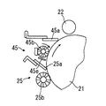
図8を参照して、本実施の形態4における潤滑剤供給装置45は、前記各実施の形態1のものとは異なり、塗布ブラシ45bの回転方向が感光体ドラム21の回転方向と同方向になるように構成されている。すなわち、塗布ブラシ45bの回転方向は、感光体ドラム21との摺接位置において、感光体ドラム21の回転方向(走行方向)と逆方向(カウンタ方向)になるように構成されている。
Referring to FIG. 8, the
このような場合にも、前記各実施の形態と同様のメカニズムで感光体ドラム21上への潤滑剤の供給がおこなわれ、潤滑剤の飛散が生じる。すなわち、潤滑剤Kを担持した塗布ブラシ45bのブラシ毛は、感光体ドラム21との摺接位置で、回転方向とは異なる方向に倒毛する。そして、回転方向とは異なる方向に倒毛したブラシ毛は、塗布ブラシ45bの回転に沿って摺接位置を通過した直後に、その復元力によって感光体ドラム21の回転方向上流側に勢いよく変位する。この反発力によってブラシ毛に担持されていた潤滑剤Kが塗布ブラシ45bから離脱・飛翔して、摺接位置に対して感光体ドラム回転方向上流側(塗布ブラシ45b回転方向下流側)で感光体ドラム21上に付着する。
このとき、摺接位置の近傍で塗布ブラシ45bから離脱・飛翔する潤滑剤Kは、その一部が感光体ドラム21以外の位置に向けて飛翔する。ところが、本実施の形態4における潤滑剤供給装置45においても、塗布ブラシ45bと感光体ドラム21との摺接位置の近傍であって塗布ブラシ45bの回転方向下流側に規制部材45eが設置されている。これにより、感光体ドラム21以外の位置に向けて飛翔する潤滑剤の進路を感光体ドラム21側に変えることができる。
Even in such a case, the lubricant is supplied onto the
At this time, a part of the lubricant K that detaches and flies from the
なお、本実施の形態4では、塗布ブラシ45bの回転方向が前記各実施の形態のものとは異なるために、感光体ドラム21上に供給された潤滑剤は、感光体ドラム21の回転に沿って再び塗布ブラシ45bとの当接位置(摺接位置)に達する。これにより、感光体ドラム21上に供給された潤滑剤は、塗布ブラシ45bの押圧されて、感光体ドラム21上に適度に薄層化されることになる。したがって、本実施の形態4における構成によれば、塗布ブレード45aを別に設置する必要がなくなって部品点数を軽減することができる。
In the fourth embodiment, since the rotation direction of the
以上説明したように、本実施の形態4によれば、前記各実施の形態と同様に、塗布ブラシ45b(ブラシ状回転部材)と感光体ドラム21(像担持体)との摺接位置の近傍であって塗布ブラシ45bの回転方向下流側に規制部材45eを設置しているために、潤滑剤Kの飛散を確実に抑止することができる。
As described above, according to the fourth embodiment, as in each of the above-described embodiments, the vicinity of the sliding contact position between the
なお、本発明が前記各実施の形態に限定されず、本発明の技術思想の範囲内において、前記各実施の形態の中で示唆した以外にも、前記各実施の形態は適宜変更され得ることは明らかである。また、前記構成部材の数、位置、形状等は前記各実施の形態に限定されず、本発明を実施する上で好適な数、位置、形状等にすることができる。 It should be noted that the present invention is not limited to the above-described embodiments, and within the scope of the technical idea of the present invention, the embodiments can be modified as appropriate in addition to those suggested in the embodiments. Is clear. In addition, the number, position, shape, and the like of the constituent members are not limited to the above embodiments, and can be set to a number, position, shape, and the like that are suitable for carrying out the present invention.
1 画像形成装置本体(装置本体)、
20、20Y、20M、20C、20BK プロセスカートリッジ、
21 感光体ドラム(像担持体)、 22 帯電部、
23、23Y、23M、23C、23BK 現像装置、
25 クリーニング装置、
25a クリーニングブレード、 25b クリーニングブラシ、
45 潤滑剤供給装置、
45a 塗布ブレード、
45b 塗布ブラシ(ブラシ状回転部材)、
45c 固形潤滑剤、 45d 圧縮スプリング、
45e 規制部材。
1 image forming apparatus body (apparatus body),
20, 20Y, 20M, 20C, 20BK Process cartridge,
21 photosensitive drum (image carrier), 22 charging unit,
23, 23Y, 23M, 23C, 23BK developing device,
25 Cleaning device,
25a cleaning blade, 25b cleaning brush,
45 Lubricant supply device,
45a coating blade,
45b Application brush (brush-like rotating member),
45c solid lubricant, 45d compression spring,
45e Restricting member.
この発明は以上述べた事項に基づくものであり、すなわち、この発明の請求項1記載の発明にかかる潤滑剤供給装置は、像担持体上に潤滑剤を供給する潤滑剤供給装置であって、潤滑剤を担持するとともに前記像担持体上に摺接位置で摺接するブラシ毛が周設されたブラシ状回転部材と、前記ブラシ状回転部材の回転方向下流側であって前記摺接位置に近接するとともに、前記摺接位置の近傍で前記ブラシ状回転部材から離脱して前記像担持体以外の位置に向けて飛散する潤滑剤を規制する規制部材と、を備え、前記規制部材は、導電性材料からなるとともに、潤滑剤の帯電極性と同じ極性の電圧が印加されるものである。 The present invention is based on the above-described matters, that is, the lubricant supply device according to the first aspect of the present invention is a lubricant supply device for supplying a lubricant onto the image carrier, A brush-like rotating member that carries a lubricant and that has brush bristles that are slidably contacted on the image bearing member at the sliding contact position, and is close to the sliding contact position on the downstream side in the rotation direction of the brush-shaped rotating member. And a regulating member that regulates the lubricant that separates from the brush-like rotating member near the sliding contact position and scatters toward a position other than the image carrier, and the regulating member is conductive. It is made of a material and is applied with a voltage having the same polarity as the charging polarity of the lubricant .
また、請求項4記載の発明にかかる潤滑剤供給装置は、前記請求項1〜請求項3のいずれかに記載の発明において、前記ブラシ状回転部材の前記ブラシ毛に当接する固形潤滑剤をさらに備えたものである。 According to a fourth aspect of the present invention, there is provided the lubricant supply device according to any one of the first to third aspects, further comprising a solid lubricant that contacts the brush bristles of the brush-like rotating member. It is provided.
また、請求項5記載の発明にかかる潤滑剤供給装置は、前記請求項1〜請求項4のいずれかに記載の発明において、前記潤滑剤を、ステアリン酸亜鉛としたものである。 A lubricant supply device according to a fifth aspect of the present invention is the lubricant supply device according to any one of the first to fourth aspects, wherein the lubricant is zinc stearate.
また、請求項6記載の発明にかかる潤滑剤供給装置は、前記請求項1〜請求項5のいずれかに記載の発明において、前記像担持体は、架橋構造を有するとともに電荷輸送材を分散してなるバインダー樹脂で形成された保護層をその表面に具備したものである。 According to a sixth aspect of the present invention, there is provided the lubricant supply device according to any one of the first to fifth aspects, wherein the image carrier has a crosslinked structure and a charge transport material is dispersed. A protective layer formed of a binder resin is provided on the surface.
また、請求項7記載の発明にかかる潤滑剤供給装置は、前記請求項1〜請求項6のいずれかに記載の発明において、前記像担持体上をクリーニングするクリーニング装置に対して前記像担持体の走行方向下流側に配設されたものである。 According to a seventh aspect of the present invention, there is provided the lubricant supply device according to any one of the first to sixth aspects, wherein the image carrier is used with respect to a cleaning device for cleaning the image carrier. It is arrange | positioned in the driving | running | working direction downstream.
また、請求項8記載の発明にかかる潤滑剤供給装置は、前記請求項1〜請求項6のいずれかに記載の発明において、前記像担持体上をクリーニングするクリーニング装置に内設されたものである。 According to an eighth aspect of the present invention, there is provided a lubricant supply device according to any one of the first to sixth aspects , wherein the lubricant supply device is installed in a cleaning device for cleaning the image carrier. is there.
また、請求項9記載の発明にかかるクリーニング装置は、像担持体上をクリーニングするクリーニング装置であって、請求項1〜請求項8のいずれかに記載の潤滑剤供給装置を備えたものである。 According to a ninth aspect of the present invention, there is provided a cleaning device for cleaning an image bearing member, comprising the lubricant supply device according to any one of the first to eighth aspects. .
また、この発明の請求項10記載の発明にかかるプロセスカートリッジは、画像形成装置の装置本体に対して着脱自在に設置されるプロセスカートリッジであって、請求項1〜請求項8のいずれかに記載の潤滑剤供給装置と前記像担持体とが一体化されたものである。 A process cartridge according to a tenth aspect of the present invention is a process cartridge that is detachably attached to the apparatus main body of the image forming apparatus, and is according to any one of the first to eighth aspects. The lubricant supply device and the image carrier are integrated.
また、この発明の請求項11記載の発明にかかる画像形成装置は、請求項1〜請求項8のいずれかに記載の潤滑剤供給装置と前記像担持体とを備えたものである。 An image forming apparatus according to an eleventh aspect of the present invention includes the lubricant supply device according to any one of the first to eighth aspects and the image carrier.
Claims (12)
潤滑剤を担持するとともに前記像担持体上に摺接位置で摺接するブラシ毛が周設されたブラシ状回転部材と、
前記ブラシ状回転部材の回転方向下流側であって前記摺接位置に近接するとともに、前記摺接位置の近傍で前記ブラシ状回転部材から離脱して前記像担持体以外の位置に向けて飛散する潤滑剤を規制する規制部材と、
を備えたことを特徴とする潤滑剤供給装置。 A lubricant supply device for supplying a lubricant onto an image carrier,
A brush-like rotating member around which brush bristles that carry a lubricant and are slidably contacted at a sliding contact position on the image carrier;
The brush-like rotating member is downstream in the rotation direction and close to the sliding contact position, and is separated from the brush-like rotating member in the vicinity of the sliding contact position and scattered toward a position other than the image carrier. A regulating member that regulates the lubricant;
A lubricant supply device comprising:
前記規制部材は、前記像担持体に当接することを特徴とする請求項1に記載の潤滑剤供給装置。 The rotation direction of the brush-like rotating member is the same as the traveling direction of the image carrier at the sliding contact position,
The lubricant supply device according to claim 1, wherein the regulating member is in contact with the image carrier.
請求項1〜請求項9のいずれかに記載の潤滑剤供給装置を備えたことを特徴とするクリーニング装置。 A cleaning device for cleaning an image carrier,
A cleaning device comprising the lubricant supply device according to claim 1.
請求項1〜請求項9のいずれかに記載の潤滑剤供給装置と前記像担持体とが一体化されたことを特徴とするプロセスカートリッジ。 A process cartridge that is detachably installed on the main body of the image forming apparatus,
10. A process cartridge, wherein the lubricant supply device according to claim 1 and the image carrier are integrated.
Priority Applications (1)
| Application Number | Priority Date | Filing Date | Title |
|---|---|---|---|
| JP2011241964A JP2012058749A (en) | 2011-11-04 | 2011-11-04 | Lubricant supply device, cleaning device, process cartridge, and image forming apparatus |
Applications Claiming Priority (1)
| Application Number | Priority Date | Filing Date | Title |
|---|---|---|---|
| JP2011241964A JP2012058749A (en) | 2011-11-04 | 2011-11-04 | Lubricant supply device, cleaning device, process cartridge, and image forming apparatus |
Related Parent Applications (1)
| Application Number | Title | Priority Date | Filing Date |
|---|---|---|---|
| JP2006205722A Division JP2008032966A (en) | 2006-07-28 | 2006-07-28 | Lubricant supply device, cleaning device, process cartridge and image forming apparatus |
Publications (1)
| Publication Number | Publication Date |
|---|---|
| JP2012058749A true JP2012058749A (en) | 2012-03-22 |
Family
ID=46055840
Family Applications (1)
| Application Number | Title | Priority Date | Filing Date |
|---|---|---|---|
| JP2011241964A Pending JP2012058749A (en) | 2011-11-04 | 2011-11-04 | Lubricant supply device, cleaning device, process cartridge, and image forming apparatus |
Country Status (1)
| Country | Link |
|---|---|
| JP (1) | JP2012058749A (en) |
Citations (6)
| Publication number | Priority date | Publication date | Assignee | Title |
|---|---|---|---|---|
| JPS5532080A (en) * | 1978-08-29 | 1980-03-06 | Ricoh Co Ltd | Toner scatter preventive device in electrophotographic copier |
| JPS57108264U (en) * | 1980-12-25 | 1982-07-03 | ||
| JP2003029550A (en) * | 2001-07-13 | 2003-01-31 | Ricoh Co Ltd | Image forming device |
| JP2005018047A (en) * | 2003-06-06 | 2005-01-20 | Ricoh Co Ltd | Image forming apparatus and process cartridge |
| JP2006163318A (en) * | 2004-12-10 | 2006-06-22 | Ricoh Co Ltd | Image forming apparatus |
| JP2006195348A (en) * | 2005-01-17 | 2006-07-27 | Ricoh Co Ltd | Process unit and image forming apparatus |
-
2011
- 2011-11-04 JP JP2011241964A patent/JP2012058749A/en active Pending
Patent Citations (6)
| Publication number | Priority date | Publication date | Assignee | Title |
|---|---|---|---|---|
| JPS5532080A (en) * | 1978-08-29 | 1980-03-06 | Ricoh Co Ltd | Toner scatter preventive device in electrophotographic copier |
| JPS57108264U (en) * | 1980-12-25 | 1982-07-03 | ||
| JP2003029550A (en) * | 2001-07-13 | 2003-01-31 | Ricoh Co Ltd | Image forming device |
| JP2005018047A (en) * | 2003-06-06 | 2005-01-20 | Ricoh Co Ltd | Image forming apparatus and process cartridge |
| JP2006163318A (en) * | 2004-12-10 | 2006-06-22 | Ricoh Co Ltd | Image forming apparatus |
| JP2006195348A (en) * | 2005-01-17 | 2006-07-27 | Ricoh Co Ltd | Process unit and image forming apparatus |
Similar Documents
| Publication | Publication Date | Title |
|---|---|---|
| JP4756548B2 (en) | Lubricant supply device, cleaning device, process cartridge, and image forming apparatus | |
| JP5454905B2 (en) | Image forming apparatus | |
| EP0726503B1 (en) | Image-forming method and image-forming apparatus | |
| JP5532395B2 (en) | Lubricant supply device, cleaning device, process cartridge, and image forming apparatus | |
| JP2004109631A (en) | Image forming apparatus and processing cartridge | |
| JP2004117389A (en) | Transfer method, image forming method and image forming apparatus | |
| JP5610151B2 (en) | Cleaning device, process cartridge, and image forming apparatus | |
| JP2008129098A (en) | Image forming apparatus | |
| JP2008032966A (en) | Lubricant supply device, cleaning device, process cartridge and image forming apparatus | |
| JP2006276158A (en) | Process cartridge, image forming device, cleaning method, and cleaning apparatus | |
| JP5233576B2 (en) | Lubricant supply device, cleaning device, process cartridge, and image forming apparatus | |
| JP2008008925A (en) | Lubricant supply device, cleaning device, process cartridge and image forming apparatus | |
| JP2013182126A (en) | Lubricant supply device, cleaning device, process cartridge, and image forming apparatus | |
| JP2007240894A (en) | Lubricant supply device, cleaning device, processing cartridge, and image forming apparatus | |
| JP5100106B2 (en) | Lubricant supply device, process cartridge, and image forming apparatus | |
| JP4220804B2 (en) | Image forming apparatus | |
| JP2004093849A (en) | Image forming apparatus and process cartridge | |
| JP2009276482A (en) | Lubricant supplying device, cleaning device, process cartridge, and image forming apparatus | |
| JP2009139604A (en) | Lubricant supplying device, cleaning device, process cartridge, and image forming apparatus | |
| JP5803078B2 (en) | Image forming apparatus | |
| JP2012103297A (en) | Lubricant unit, lubricant supply device, process cartridge, and image forming apparatus | |
| JP2016038424A (en) | Image forming apparatus and process cartridge | |
| JP2012058749A (en) | Lubricant supply device, cleaning device, process cartridge, and image forming apparatus | |
| JP3769526B2 (en) | Image forming apparatus and process cartridge | |
| JP4220764B2 (en) | Image forming apparatus and process cartridge |
Legal Events
| Date | Code | Title | Description |
|---|---|---|---|
| A131 | Notification of reasons for refusal |
Free format text: JAPANESE INTERMEDIATE CODE: A131 Effective date: 20120330 |
|
| A521 | Written amendment |
Free format text: JAPANESE INTERMEDIATE CODE: A523 Effective date: 20120515 |
|
| A131 | Notification of reasons for refusal |
Free format text: JAPANESE INTERMEDIATE CODE: A131 Effective date: 20121122 |
|
| A02 | Decision of refusal |
Free format text: JAPANESE INTERMEDIATE CODE: A02 Effective date: 20130925 |