JP2012049376A - Plasma processing apparatus and plasma processing method - Google Patents
Plasma processing apparatus and plasma processing method Download PDFInfo
- Publication number
- JP2012049376A JP2012049376A JP2010190969A JP2010190969A JP2012049376A JP 2012049376 A JP2012049376 A JP 2012049376A JP 2010190969 A JP2010190969 A JP 2010190969A JP 2010190969 A JP2010190969 A JP 2010190969A JP 2012049376 A JP2012049376 A JP 2012049376A
- Authority
- JP
- Japan
- Prior art keywords
- etching gas
- etching
- supply means
- processing chamber
- gas
- Prior art date
- Legal status (The legal status is an assumption and is not a legal conclusion. Google has not performed a legal analysis and makes no representation as to the accuracy of the status listed.)
- Pending
Links
Images


Abstract
Description
本発明は、プラズマ処理装置およびプラズマ処理方法であり、特に半導体素子基板等の被処理材を、プラズマを用いてエッチング処理を施すのに好適なプラズマ処理装置およびプラズマ処理方法に関するものである。 The present invention relates to a plasma processing apparatus and a plasma processing method, and more particularly to a plasma processing apparatus and a plasma processing method suitable for performing an etching process on a material to be processed such as a semiconductor element substrate using plasma.
半導体製造工程では、一般にプラズマを用いたドライエッチングが行われている。ドライエッチングを行うためのプラズマ処理装置は様々な方式が使用されている。 In the semiconductor manufacturing process, dry etching using plasma is generally performed. Various types of plasma processing apparatuses for performing dry etching are used.
一般に、プラズマ処理装置は、真空処理室、これに接続されたガス供給装置、真空処理室内の圧力を所望の値に維持する真空排気系、被処理材であるウエハを載置する電極、真空処理室内にプラズマを発生させるためのプラズマ発生手段などから構成されている。プラズマ発生手段によりシャワープレート等から真空処理室内に供給された処理ガスをプラズマ状態とすることで、ウエハ載置用電極に保持されたウエハのエッチング処理が行われる。 In general, a plasma processing apparatus includes a vacuum processing chamber, a gas supply device connected to the vacuum processing chamber, an evacuation system for maintaining the pressure in the vacuum processing chamber at a desired value, an electrode on which a wafer as a processing object is placed, a vacuum processing It comprises plasma generating means for generating plasma in the room. The processing gas supplied from the shower plate or the like into the vacuum processing chamber by the plasma generating means is changed to a plasma state, whereby the wafer held by the wafer mounting electrode is etched.
近年、半導体デバイスの集積度の向上に伴い、微細加工つまり加工精度の向上が要求されるとともに、エッチングレートの面内均一性あるいはエッチング形状におけるCD値(Critical Dimension)の面内の均一性等の向上が要求されている。また被エッチング材料も単層膜から多層膜に変化し、各層膜あるいは膜の処理中にエッチング条件を変化させる多段ステップのエッチングが多用されるようになった。これは、エッチングレートやエッチング形状の面内均一性に影響を与える要因が各層膜を構成する材料特性で異なることに起因する。被エッチング材料の面内エッチングレートの均一性は、以下の影響を受けやすい。プラズマ密度分布、ラジカル分布、ガス流れ分布、被エッチング材料のエッチング処理中の面内温度分布、エッチング反応による反応生成物分布、処理室側壁の温度設定等。これらの分布の影響は各層膜の材料特性に依存し、プラズマエッチングの場合は、エッチング処理の条件(例えば、プラズマの励起電力、使用ガスの種類、使用ガスの混合比、ガス圧力、バイアスRF電力、電極あるいはリアクタ壁等の温度設定等)を各膜層の材料によって最適化する必要がある。よって多層膜のエッチングの完了時点でエッチングレートやエッチング形状(例えばCD)の高精度の面内均一性を得ることは難しくなっている。さらに最近の半導体加工においては微細化に伴いエッチング特性の均一性はナノメートルまたはサブナノメートルのオーダーで要求されている。このため処理室内部のガス流れ分布、反応生成物流れ分布を各加工ステップにおいて最適となるように制御する必要がある。 In recent years, with the improvement in the degree of integration of semiconductor devices, fine processing, that is, improvement in processing accuracy is required, and in-plane uniformity of etching rate or in-plane uniformity of CD value (Critical Dimension) in etching shape, etc. Improvement is required. In addition, the material to be etched is also changed from a single layer film to a multilayer film, and multi-step etching that changes etching conditions during the processing of each layer film or film is frequently used. This is because the factors that affect the in-plane uniformity of the etching rate and the etching shape are different in the material characteristics constituting each layer film. The uniformity of the in-plane etching rate of the material to be etched is susceptible to the following effects. Plasma density distribution, radical distribution, gas flow distribution, in-plane temperature distribution during etching of the material to be etched, reaction product distribution due to etching reaction, temperature setting of processing chamber side wall, etc. The influence of these distributions depends on the material characteristics of each layer film. In the case of plasma etching, the conditions of the etching process (for example, plasma excitation power, type of gas used, gas mixture ratio, gas pressure, bias RF power) It is necessary to optimize the temperature setting of the electrode or reactor wall etc. according to the material of each film layer. Therefore, it is difficult to obtain highly accurate in-plane uniformity of the etching rate and the etching shape (for example, CD) at the time when the etching of the multilayer film is completed. Further, in recent semiconductor processing, with the miniaturization, uniformity of etching characteristics is required on the order of nanometers or sub-nanometers. For this reason, it is necessary to control the gas flow distribution and the reaction product flow distribution in the processing chamber so as to be optimized in each processing step.
従来のプラズマ処理装置におけるエッチングガス供給手段としては、非特許文献1記載のように、ウエハの中心部の上方に設けられた処理室上面からのエッチングガス供給手段からのみエッチングガスを供給するものが一般的である。さらに、特許文献1には、プラズマ中のイオンやラジカルの面内均一性の改善を目的とした技術として、処理室上面の複数箇所からエッチングガスを導入する技術などが知られている(特開昭62-290885号公報)。
As an etching gas supply means in a conventional plasma processing apparatus, as described in Non-Patent
従来のプラズマ処理装置におけるエッチングガス供給手段では、処理室内のガス流れ分布、反応生成物流れ分布を制御するために、処理室上面からのエッチングガス供給手段を用いるもの、処理室上面の複数箇所からエッチングガスを導入するものなどが知られている。 In the etching gas supply means in the conventional plasma processing apparatus, the etching gas supply means from the upper surface of the processing chamber is used to control the gas flow distribution and reaction product flow distribution in the processing chamber. One that introduces an etching gas is known.
しかし処理室上面からエッチングガスを供給しても、処理室内部のガス流れ分布、反応生成物流れ分布を制御できる範囲は極めて小さい。なぜなら処理室上面からのエッチングガス供給手段からのみエッチングガスを供給する場合、エッチングガスの濃度、また反応生成物濃度は、ウエハの中心部で高く、外周部で低くなることが多く、その濃度分布を変化させたり、また分布を反転させたりするようなガス流れ、反応生成物流れを形成することは難しい。さらにウエハ上に堆積させた各膜の種類によって処理ガス種、処理ガス圧力、プラズマ分布は大きく変化し、それに伴い各膜層に最適なガス流れ分布、反応生成物流れ分布も大きく変化するため、これらの制御範囲を広くしておく必要がある。処理室上面の複数箇所からエッチングガスを導入する装置でも、ウエハと処理室上面が離れているため、ウエハ近傍のガス流れ分布、反応生成物流れ分布を制御することは難しく、その制御範囲が極めて狭いという問題がある。 However, even if the etching gas is supplied from the upper surface of the processing chamber, the range in which the gas flow distribution and the reaction product flow distribution in the processing chamber can be controlled is extremely small. This is because when the etching gas is supplied only from the etching gas supply means from the upper surface of the processing chamber, the concentration of the etching gas and the reaction product concentration are often high in the central portion of the wafer and low in the outer peripheral portion. It is difficult to form a gas flow or reaction product flow that changes the flow rate or reverses the distribution. Furthermore, depending on the type of each film deposited on the wafer, the processing gas type, processing gas pressure, and plasma distribution change greatly, and accordingly, the optimal gas flow distribution and reaction product flow distribution for each film layer also change greatly. It is necessary to widen these control ranges. Even in an apparatus that introduces an etching gas from a plurality of locations on the upper surface of the processing chamber, since the wafer and the upper surface of the processing chamber are separated, it is difficult to control the gas flow distribution and reaction product flow distribution in the vicinity of the wafer, and the control range is extremely large. There is a problem of being narrow.
さらに、ウエハ上に複数の材料を堆積させた積層膜をエッチング処理する場合には、各膜の材料に最適な条件(処理ガス種、処理ガス圧力、プラズマ分布、ウエハ処理温度など)で順次エッチング処理を行う必要がある。所望のエッチング処理を施すとき、あらかじめ決められた順序に従い、エッチング処理の各段階(以下ステップと呼ぶ)を順次、進めていくエッチング処理(以下ステップエッチングと呼ぶ)において、各膜の材料によって最適なエッチング処理条件は異なり、プラズマ処理中の各膜に最適なガス流れ分布、反応生成物流れ分布も大きく変化する。従来のように処理室上面からエッチングガスを供給する場合、処理室内部のガス流れ、反応生成物流れを制御できる範囲は極めて小さい。また処理室上面の複数箇所からエッチングガスを導入する装置でも、ウエハと処理室上面が離れているため、ウエハ近傍のガス流れ分布、反応生成物流れ分布を制御することは難しく、その制御範囲は極めて狭い。各ステップ間で各堆積膜に最適となるように、高精度にエッチングガス流れ分布、反応生成物流れ分布を変化させることができない。 In addition, when etching a laminated film in which multiple materials are deposited on a wafer, etching is performed sequentially under the optimum conditions (processing gas type, processing gas pressure, plasma distribution, wafer processing temperature, etc.) for each film material. It is necessary to perform processing. When a desired etching process is performed, each stage of the etching process (hereinafter referred to as a step) is sequentially performed according to a predetermined order. The etching process conditions are different, and the optimum gas flow distribution and reaction product flow distribution for each film during the plasma processing change greatly. When the etching gas is supplied from the upper surface of the processing chamber as in the prior art, the range in which the gas flow and the reaction product flow in the processing chamber can be controlled is extremely small. Even in an apparatus that introduces etching gas from multiple locations on the upper surface of the processing chamber, it is difficult to control the gas flow distribution and reaction product flow distribution in the vicinity of the wafer because the wafer and the upper surface of the processing chamber are separated from each other. Very narrow. The etching gas flow distribution and reaction product flow distribution cannot be changed with high accuracy so as to be optimal for each deposited film between the steps.
一方、ウエハ径がΦ300mmと大きくなるとともに、ウエハ面内のプラズマ分布や反応生成物分布などが不均一になりやすくなってきている。この対応として、ガス流れ分布や反応生成物流れ分布を面内で均一にするのではなく、エッチング特性が均一になるように面内でガス流れ分布や反応生成物流れを制御する方法も必要とされている。すなわち、ウエハ近傍での高精度なガス流れ制御、反応生成物流れ制御も必要となってきている。 On the other hand, as the wafer diameter becomes as large as Φ300 mm, the plasma distribution, reaction product distribution, etc. within the wafer surface tend to be non-uniform. As a countermeasure, a method for controlling the gas flow distribution and the reaction product flow in the plane so that the etching characteristics are uniform is required instead of making the gas flow distribution and the reaction product flow distribution uniform in the plane. Has been. In other words, highly accurate gas flow control and reaction product flow control in the vicinity of the wafer are required.
そこで本発明では、処理ガス種、処理圧力、プラズマ分布、ウエハ温度分布などの変化に応じてガス流れ分布、反応生成物流れ分布を制御することができ、さらに制御できるガス流れ分布の範囲、反応生成物流れ分布の範囲を広くすることができるプラズマ処理装置およびプラズマ処理方法を供給することを目的とする。 Therefore, in the present invention, the gas flow distribution and the reaction product flow distribution can be controlled in accordance with changes in the processing gas type, processing pressure, plasma distribution, wafer temperature distribution, etc. An object of the present invention is to provide a plasma processing apparatus and a plasma processing method capable of widening the range of product flow distribution.
さらに、ウエハ上の積層膜をプラズマ処理する際、あらかじめ決められた順序に従い、プラズマ処理の各ステップを順次、進めていくステップ処理において、各ステップ間で高精度にガス流れ分布、反応生成物流れ分布を変化させることを目的とする。 Further, when plasma processing is performed on the laminated film on the wafer, the gas flow distribution and the reaction product flow are accurately performed between the steps in the step processing in which the plasma processing steps are sequentially performed according to a predetermined order. The purpose is to change the distribution.
本発明では、処理ガス種、処理圧力、プラズマ分布、ウエハ温度分布などの変化に応じて処理室内のガス流れ分布、反応生成物流れを制御し、さらに制御できるガス流れ分布の範囲、反応生成物流れ分布の範囲を広くするため、第一のエッチングガス供給手段と第二のエッチングガス供給手段を設け、それぞれの供給手段から導入されるエッチングガスを調整することで、処理室内のガス流れ分布、反応生成物流れ分布を高精度に制御することができる。 In the present invention, the gas flow distribution and reaction product flow in the processing chamber are controlled in accordance with changes in the processing gas type, processing pressure, plasma distribution, wafer temperature distribution, etc., and the range of the gas flow distribution that can be further controlled, the reaction product In order to widen the range of the flow distribution, the first etching gas supply means and the second etching gas supply means are provided, and the gas flow distribution in the processing chamber is adjusted by adjusting the etching gas introduced from each supply means, The reaction product flow distribution can be controlled with high accuracy.
また第一のエッチングガス供給手段は、1種類以上のエッチングガスを供給するための1種類以上のガスボンベと、前記1種類以上のエッチングガスを導入するための前記1種類以上のガスボンベに対応したガス配管とガスバルブと、前記1種類以上のエッチングガスの供給量を制御するための前記1種類以上のエッチングガスに対応した1種類以上のガス流量制御器と、前記1種類以上の供給量を制御されたエッチングガスを混合し処理室に導入するためのガス配管とから構成され、かつ前記第一のエッチングガス供給手段とは別に、第二のエッチングガス供給手段は、1種類以上のエッチングガスを供給するための1種類以上のガスボンベと、前記1種類以上のエッチングガスを導入するための前記1種類以上のガスボンベに対応したガス配管とガスバルブと、前記1種類以上のエッチングガスの供給量を制御するための前記1種類以上のエッチングガスに対応した1種類以上のガス流量制御器と、前記1種類以上の供給量を制御されたエッチングガスを混合し処理室に導入するためのガス配管とから構成される。 The first etching gas supply means includes one or more types of gas cylinders for supplying one or more types of etching gas and a gas corresponding to the one or more types of gas cylinders for introducing the one or more types of etching gas. A pipe, a gas valve, one or more types of gas flow controllers corresponding to the one or more types of etching gas for controlling the supply amount of the one or more types of etching gas, and the one or more types of supply amounts are controlled. In addition to the first etching gas supply means, the second etching gas supply means supplies one or more types of etching gases. One or more types of gas cylinders for performing the above and one or more types of gas cylinders for introducing the one or more types of etching gas. A pipe, a gas valve, one or more types of gas flow controllers corresponding to the one or more types of etching gas for controlling the supply amount of the one or more types of etching gas, and the one or more types of supply amounts are controlled. And a gas pipe for mixing and introducing the etching gas into the processing chamber.
以上の構成により、それぞれのエッチングガス供給手段から導入されるエッチングガスの、それぞれのガス種、ガス流量、ガス混合比を制御できる。また第二のエッチングガス供給手段は、前記被処理材の載置用電極の周辺に設けられたサセプタに接続し、エッチングガスを前記被処理材の周辺からも導入できるようにしてもよく、より高精度に、より広い制御範囲で、処理室内のガス流れ分布、反応生成物流れ分布を制御することができる。 With the above configuration, each gas type, gas flow rate, and gas mixture ratio of the etching gas introduced from each etching gas supply means can be controlled. The second etching gas supply means may be connected to a susceptor provided around the electrode for mounting the material to be processed so that the etching gas can be introduced from the periphery of the material to be processed. The gas flow distribution and reaction product flow distribution in the processing chamber can be controlled with high accuracy and in a wider control range.
さらに、以上の手段により、ウエハ上の積層膜をエッチング処理する際、あらかじめ決められた順序に従い、エッチング処理の各ステップを順次、進めていくステップエッチングにおいても、各ステップ間で高精度に処理室内のガス流れ分布、反応生成物流れ分布を変化させることが可能となる。 Further, when etching the laminated film on the wafer by the above means, even in the step etching in which each step of the etching process is sequentially advanced according to a predetermined order, the processing chamber is highly accurate between each step. It is possible to change the gas flow distribution and the reaction product flow distribution.
本発明のプラズマ処理装置および処理方法では、処理ガス種、処理圧力、プラズマ分布、ウエハ温度分布などの変化に応じて処理室内のガス流れ分布、反応生成物流れを制御し、さらに制御できるガス流れ分布の範囲、反応生成物流れ分布の範囲を広くできるという効果がある。本発明では、第一のエッチングガス供給手段と第二のエッチングガス供給手段を設け、それぞれの供給手段から導入されるエッチングガスを調整することができ、処理室内のガス流れ分布、反応生成物流れ分布を制御することができるという効果がある。 In the plasma processing apparatus and the processing method of the present invention, the gas flow that can control and further control the gas flow distribution and reaction product flow in the processing chamber in accordance with changes in the processing gas type, processing pressure, plasma distribution, wafer temperature distribution, and the like. There is an effect that the range of distribution and the range of reaction product flow distribution can be widened. In the present invention, the first etching gas supply means and the second etching gas supply means are provided, and the etching gas introduced from each supply means can be adjusted, and the gas flow distribution in the processing chamber, the reaction product flow There is an effect that the distribution can be controlled.
また第一のエッチングガス供給手段は、1種類以上のエッチングガスを供給するための1種類以上のガスボンベと、前記1種類以上のエッチングガスを導入するための前記1種類以上のガスボンベに対応したガス配管とガスバルブと、前記1種類以上のエッチングガスの供給量を制御するための前記1種類以上のエッチングガスに対応した1種類以上のガス流量制御器と、前記1種類以上の供給量を制御されたエッチングガスを混合し処理室に導入するためのガス配管とから構成され、かつ前記第一のエッチングガス供給手段とは別に、第二のエッチングガス供給手段は、1種類以上のエッチングガスを供給するための1種類以上のガスボンベと、前記1種類以上のエッチングガスを導入するための前記1種類以上のガスボンベに対応したガス配管とガスバルブと、前記1種類以上のエッチングガスの供給量を制御するための前記1種類以上のエッチングガスに対応した1種類以上のガス流量制御器と、前記1種類以上の供給量を制御されたエッチングガスを混合し処理室に導入するためのガス配管とから構成される。これによりそれぞれのエッチングガス供給手段から導入されるエッチングガスの、それぞれのガス種、ガス流量、ガス混合比を制御できるという効果がある。また第二のエッチングガス供給手段は、前記被処理材の載置用電極の周辺に設けられたサセプタに接続し、エッチングガスを前記被処理材の周辺からも導入できるようにしてもよく、より高精度に、より広い制御範囲で、処理室内のガス流れ分布、反応生成物流れ分布を制御できるという効果がある。 The first etching gas supply means includes one or more types of gas cylinders for supplying one or more types of etching gas and a gas corresponding to the one or more types of gas cylinders for introducing the one or more types of etching gas. A pipe, a gas valve, one or more types of gas flow controllers corresponding to the one or more types of etching gas for controlling the supply amount of the one or more types of etching gas, and the one or more types of supply amounts are controlled. In addition to the first etching gas supply means, the second etching gas supply means supplies one or more types of etching gases. One or more types of gas cylinders for performing the above and one or more types of gas cylinders for introducing the one or more types of etching gas. A pipe, a gas valve, one or more types of gas flow controllers corresponding to the one or more types of etching gas for controlling the supply amount of the one or more types of etching gas, and the one or more types of supply amounts are controlled. And a gas pipe for mixing and introducing the etching gas into the processing chamber. Thereby, there is an effect that each gas type, gas flow rate, and gas mixture ratio of the etching gas introduced from each etching gas supply means can be controlled. The second etching gas supply means may be connected to a susceptor provided around the electrode for mounting the material to be processed so that the etching gas can be introduced from the periphery of the material to be processed. There is an effect that the gas flow distribution and the reaction product flow distribution in the processing chamber can be controlled with high accuracy and in a wider control range.
上記の本発明においては、ウエハ上の積層膜をエッチング処理する際、あらかじめ決められた順序に従い、エッチング処理の各ステップを順次、進めていくステップエッチングにおいても、各ステップ間で高精度に処理室内のガス流れ分布、反応生成物流れ分布を変化させることが可能となるという効果がある。 In the above-mentioned present invention, when etching the laminated film on the wafer, even in the step etching in which each step of the etching process is sequentially advanced according to a predetermined order, the processing chamber is highly accurate between the steps. It is possible to change the gas flow distribution and the reaction product flow distribution.
(実施例1)
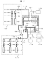
以下、本発明の一実施例であるマイクロ波ECR(Electron Cyclotron Resonance)エッチング装置を図1により説明する。上部が開放された真空容器101の上部に、真空容器101内にエッチングガスを封入するための誘電体窓103(例えば石英製)を設置することにより処理室104を形成する。また、真空容器101には真空排気口106を介し真空排気装置(図示省略)が接続されている。
Example 1
A microwave ECR (Electron Cyclotron Resonance) etching apparatus according to an embodiment of the present invention will be described below with reference to FIG. A processing chamber 104 is formed by installing a dielectric window 103 (for example, made of quartz) for enclosing an etching gas in the vacuum vessel 101 on the upper portion of the vacuum vessel 101 whose top is opened. In addition, a vacuum exhaust device (not shown) is connected to the vacuum vessel 101 via a
プラズマを生成するための電力を処理室104に伝送するため、誘電体窓103の上方には電磁波を放射する導波管107(またはアンテナ)が設けられる。導波管107(またはアンテナ)へ伝送される電磁波は電磁波発生用電源109から発振させる。電磁波の周波数は特に限定されないが、本実施例では2.45GHzのマイクロ波を使用する。処理室104の外周部には、磁場を形成する磁場発生コイル110が設けてあり、電磁波発生用電源109より発振された電力は、形成された磁場との相互作用により、処理室104内に高密度プラズマを生成する。
A waveguide 107 (or an antenna) that radiates electromagnetic waves is provided above the dielectric window 103 in order to transmit power for generating plasma to the processing chamber 104. The electromagnetic wave transmitted to the waveguide 107 (or antenna) is oscillated from the electromagnetic wave generating
また、誘電体窓103に対向して真空容器101の下部にはウエハ載置用電極111が設けられる。ウエハ載置用電極111は電極表面が溶射膜(図示省略)で被覆されており、高周波フィルター115を介して直流電源116が接続されている。さらに、ウエハ載置用電源111には、マッチング回路113を介して高周波電源114が接続される。 Further, a wafer mounting electrode 111 is provided below the vacuum vessel 101 so as to face the dielectric window 103. The wafer mounting electrode 111 has an electrode surface covered with a sprayed film (not shown), and a DC power supply 116 is connected through a high frequency filter 115. Further, a high frequency power supply 114 is connected to the wafer mounting power supply 111 via a matching circuit 113.
処理室104内に搬送されたウエハ112は、直流電源116から印加される直流電圧の静電気力でウエハ載置用電極111上に吸着され、処理室104内に所望のエッチングガスを供給した後、真空容器101内を所定の圧力とし、処理室104内にプラズマを発生させる。ウエハ載置用電極111に接続された高周波電源114から高周波電力を印加することにより、プラズマからウエハへイオンを引き込み、ウエハ112がエッチング処理される。 The wafer 112 transferred into the processing chamber 104 is adsorbed on the wafer mounting electrode 111 by the electrostatic force of the DC voltage applied from the DC power supply 116, and after supplying a desired etching gas into the processing chamber 104, The inside of the vacuum chamber 101 is set to a predetermined pressure, and plasma is generated in the processing chamber 104. By applying a high frequency power from a high frequency power source 114 connected to the wafer mounting electrode 111, ions are drawn from the plasma into the wafer, and the wafer 112 is etched.
次に、本実施例におけるエッチングガス供給手段120,130を図1により説明する。本実施例のプラズマ処理装置に用いられる第一のエッチングガス供給手段120には、処理室104にエッチングガスを導入するためのシャワープレート102(例えば石英製)と、第一のエッチングガスを供給する配管121、第一のエッチングガスを供給するバルブ122、第一のエッチングガスにおいてそれぞれのガスの供給量を制御するガス流量制御器123、第一のエッチングガスにおいてそれぞれのガスを供給するバルブ124、各ガスボンベ125が接続される。エッチングガスを導入するためのシャワープレート102は、真空容器101の上部に設けられることが多く、本実施例では、誘電体窓103の直下に設置してある。各ガスボンベ125は、1種類以上で複数のガスボンベで構成され、被処理材料(以下、実施例の説明においては、「ウエハ」として統一する)に最適な混合ガスが配管121により処理室104内に供給される。
Next, the etching gas supply means 120 and 130 in this embodiment will be described with reference to FIG. The first etching gas supply means 120 used in the plasma processing apparatus of this embodiment is supplied with a shower plate 102 (for example, made of quartz) for introducing the etching gas into the processing chamber 104 and the first etching gas. A pipe 121, a
また第二のエッチングガス供給手段130には、真空容器101下部のウエハ載置用電極111の周辺から処理室104にエッチングガスを導入するためのガス導入部136と、第二のエッチングガスを供給する配管131、第二のエッチングガスを供給するバルブ132、第二のエッチングガスにおいてそれぞれのガスの供給量を制御するガス流量制御器133、第二のエッチングガスにおいてそれぞれのガスを供給するバルブ134、各ガスボンベ135が接続される。本実施例では、ウエハ載置用電極111の周りに設置されたサセプタ105(例えば石英製)内にエッチングガスを導入するためのガス導入部136を設け、第二のエッチングガスを供給する配管が接続される。第二のエッチングガスは3系統のガスの混合ガスから構成され、1系統目はエッチングを促進させるガス(例えば、塩素ガス)、2系統目はエッチングを抑制させるガス(例えば、四フッ化炭素ガス)、3系統目はエッチングに影響を及ぼさない不活性ガス(例えば、アルゴンガス)としている。第一のエッチングガス供給手段120から導入されたエッチングガスは、シャワープレート102付近では、シャワープレートからウエハ112への方向のガス流線を持っているが、ウエハ112近傍ではウエハ112の中心からウエハ112の外周方向のガス流線を持つ。ウエハ112のエッチング反応は、ウエハ112近傍のエッチングガス雰囲気によってエッチング速度やエッチング形状が決定される。
The second etching gas supply means 130 is supplied with a
第一のエッチングガスのウエハ112近傍でのガス流線に影響を与えられるように、第二のエッチングガスは、第二のエッチングガスを導入するためのガス導入部136からウエハ112の中心方向へ向かう流線を持つようにする。つまり第二のエッチングガスを導入するためのガス導入部136は、図6(A)に示すように、第二のエッチングガスをウエハに対して概略平行方向にウエハ外周から概略中心方向へ吹き出すような形状が望ましい。よって本実施例では、サセプタ105の内径部の全周にスリット状の開口を設けている。また、図6(B)に示すように、スリット状の開口部から導入されるガスを中心方向から傾けて放射させる構成とすることで、開口部の内側近傍におけるガス溜まりを防止するよう構成してもよい。
The second etching gas is directed from the
本実施例では図1に示すように、サセプタ105内にガス導入部136を設けているが、サセプタ105とガス導入部136を独立させウエハ載置用電極111の周辺に設けても同様の効果が得られる。また第一のエッチングガス供給手段120と第二のエッチングガス供給手段130において、それぞれガスボンベ125,135を独立に設けてあるが、各ガスボンベからの配管を分岐し、第一のエッチングガスを供給する手段120と第二のエッチングガスを供給する手段130に接続してもよい。さらに第二のエッチングガスを供給する配管は3系統に限られず、複数のガス配管を接続してもよい。
In this embodiment, as shown in FIG. 1, the
ガス導入部136の一例は、その斜視図を図7(A)に示すが、ウエハにおけるエッチングレートやエッチング形状の均一性を著しく低下させない限り、スリット状の開口を全周に設ける必要はなく、1個以上複数のスリット状の開口部や1個以上複数のホール状開口部を設けてもよい。
An example of the
さらに図2に示すように、第二のエッチングガス供給手段130を接続しているサセプタ内にコンダクタンスを与えるためのガスだまり201を設けてもよく、この場合サセプタの開口部において第二のエッチングガス供給手段130から導入されたエッチングガスが全周方向に均一に噴出すという効果がある。その一例は、その斜視図を図7(B)に示す。また第二のエッチングガス供給手段130はサセプタ105に1箇所から接続する必要はなく、1個以上複数の接続箇所を設けてもよい。この場合もサセプタの開口部から導入されるエッチングガスの均一性が向上し、処理室104内部のガス流れ分布、反応生成物流れ分布の周方向均一性が向上するという効果が得られる。
Further, as shown in FIG. 2, a
サセプタ105の材料は、石英材に限られるものではない。例えば、アルミナ材といったセラミックス材でも同様の効果を得られる。さらにサセプタ105はその内部に第二のエッチングガス供給手段130から導入されたエッチングガスを流す流路を形成する必要があるが、この流路を形成するため、サセプタ105の構造は、複数の部品からなる構造でも、さらには複数の部品を貼り合わせた構造でもよい。 The material of the susceptor 105 is not limited to quartz material. For example, the same effect can be obtained with a ceramic material such as an alumina material. Furthermore, the susceptor 105 needs to form a flow path for flowing the etching gas introduced from the second etching gas supply means 130 therein. In order to form this flow path, the structure of the susceptor 105 has a plurality of components. Or a structure in which a plurality of components are bonded together.
サセプタ105の構造が複数の部品からなる場合は、部材のコストを下げられる効果があり、また複数の部品を貼り合わせた構造の場合には、第二のエッチングガス供給手段130から導入されたエッチングガスを流す流路からのガスの漏れを少なくし、またサセプタの開口部から導入するガスの周方向均一性を向上するという効果が得られる。 When the structure of the susceptor 105 is composed of a plurality of parts, there is an effect that the cost of the member can be reduced. In the case of a structure in which a plurality of parts are bonded together, the etching introduced from the second etching gas supply means 130 The effects of reducing gas leakage from the gas flow path and improving the circumferential uniformity of the gas introduced from the opening of the susceptor are obtained.
上記の本発明の実施例では、第一のエッチングガスの供給手段120におけるシャワープレート102のエッチングガス導入穴の配置を同心円の円環状、または円形状としている。さらに第二のエッチングガスの供給手段130におけるガス導入部136の配置も同心円の円環状としている。同心円の円環状、円形状とすることで、エッチングガス流れ分布をウエハ112に対して中心軸対称とすることができ、例えばウエハ面内のエッチングレート分布、エッチング形状(CDを含む)を制御しやすいという効果がある。
In the embodiment of the present invention described above, the arrangement of the etching gas introduction holes of the shower plate 102 in the first etching gas supply means 120 is a concentric annular shape or a circular shape. Furthermore, the arrangement of the
また第二のエッチングガス供給手段130から導入されたエッチングガスをサセプタ105の内径部から導入できるように内径部に設けた開口部の位置が、径方向においてウエハ112の最外周の位置よりも大きく、さらに径方向にウエハ112の最外周の位置から1mmから30mm以内の位置とすることで、高精度に処理室内のエッチングガス流れ分布、反応生成物流れ分布を制御できるという効果がある。第二のエッチングガス供給手段130のガス導入部136がウエハ112から例えば30mm以上に遠くなると、ウエハ112近傍のエッチングガス流れ、反応生成物流れを制御できない。
Further, the position of the opening provided in the inner diameter portion so that the etching gas introduced from the second etching gas supply means 130 can be introduced from the inner diameter portion of the susceptor 105 is larger than the position of the outermost periphery of the wafer 112 in the radial direction. Further, by setting the position within 1 mm to 30 mm from the position of the outermost periphery of the wafer 112 in the radial direction, there is an effect that the etching gas flow distribution and the reaction product flow distribution in the processing chamber can be controlled with high accuracy. If the
プラズマ処理を行う場合は、第一のエッチングガス供給手段の各バルブ124を開け、各ガスボンベ125からエッチング用ガス(例えば、塩素ガス、臭化水素ガス、四フッ化メタンガス、三フッ化メタン、二フッ化メタン、アルゴンガス、ヘリウムガス、酸素ガス、窒素ガス、二酸化炭素、一酸化炭素、水素、アンモニア、八フッ化プロパン、三フッ化窒素、六フッ化硫黄ガス、メタンガス、四フッ化シリコンガス、四塩化シリコンガス等)を供給し、所望のエッチングガス混合比となるようそれぞれのガス流量制御器123を制御する。第二のエッチングガス供給手段130も同様に各バルブ134を開け、各ガスボンベ135からエッチング用ガス(例えば、塩素ガス、臭化水素ガス、四フッ化メタンガス、アルゴンガス、ヘリウムガス、酸素ガス、窒素ガス、六フッ化硫黄ガス、メタンガス、CHF3ガス、NF3ガス、SiF4ガス、SiCl4ガス等)を供給し、所望のエッチングガス混合比となるようにそれぞれのガス流量制御器133を制御する。
When plasma processing is performed, each
従来のプラズマ処理装置のように第一のエッチングガス供給手段120しか設けられていない場合、処理室104内部のガス流れ、反応生成物流れを高精度に制御することは困難である。これに対して、本実施例のプラズマ処理装置のように第二のエッチングガス供給手段130を設けることで、処理室104内部のガス流れ、反応生成物流れを各加工ステップで最適に制御することができる。また処理室内部のガス流れ、反応生成物流れを高精度に制御できるため、被エッチング材料面内のエッチングレート、エッチング形状の分布を凸分布や凹分布といったように、任意に制御することが可能となる。 When only the first etching gas supply means 120 is provided as in the conventional plasma processing apparatus, it is difficult to control the gas flow and the reaction product flow inside the processing chamber 104 with high accuracy. In contrast, by providing the second etching gas supply means 130 as in the plasma processing apparatus of the present embodiment, the gas flow and reaction product flow inside the processing chamber 104 can be optimally controlled in each processing step. Can do. In addition, since the gas flow and reaction product flow inside the processing chamber can be controlled with high accuracy, the etching rate and etching shape distribution within the surface of the material to be etched can be controlled arbitrarily, such as a convex distribution or a concave distribution. It becomes.
また、本実施例においては、エッチングガスの供給手段を第一と第二の2系統としたが、2系統以上の複数のエッチングガス供給手段を設けることにより、さらに高精度にウエハ面内のエッチングレート、エッチング形状(CDを含む)を制御することが可能となる。 In this embodiment, the first and second etching gas supply means are two systems, but by providing a plurality of two or more etching gas supply means, etching in the wafer surface can be performed with higher accuracy. The rate and etching shape (including CD) can be controlled.
次に、図3で実際のエッチングレート結果を示す。本実施例においては、被エッチング材料をポリシリコン膜とし、エッチングガスとして例えば、塩素ガス、四フッ化メタンガス、アルゴンガスが用いられる。曲線301は、第一のエッチングガス供給手段120のみを用いてエッチングした場合のエッチングレートのウエハ面内分布、つまり均一性を示す。曲線302は、第二のエッチングガス供給手段130より塩素ガスを導入し、それ以外のエッチングガスを第一のエッチングガス供給手段120より導入した場合のエッチングレートのウエハ面内分布を示す。曲線303は、第二のエッチングガス供給手段130より四フッ化メタンガスを導入し、それ以外のエッチングガス、塩素ガスおよび、アルゴンガス、を第一のエッチングガス供給手段120より導入した場合のエッチングレートのウエハ面内分布を示す。 Next, FIG. 3 shows an actual etching rate result. In the present embodiment, the material to be etched is a polysilicon film, and, for example, chlorine gas, tetrafluoromethane gas, or argon gas is used as an etching gas. A curve 301 indicates the distribution in the wafer surface of the etching rate when etching is performed using only the first etching gas supply unit 120, that is, uniformity. A curve 302 shows the in-wafer distribution of the etching rate when chlorine gas is introduced from the second etching gas supply means 130 and other etching gas is introduced from the first etching gas supply means 120. A curve 303 indicates an etching rate when tetrafluoromethane gas is introduced from the second etching gas supply means 130 and other etching gas, chlorine gas, and argon gas are introduced from the first etching gas supply means 120. The wafer in-plane distribution is shown.
曲線301が示すように、第一のエッチングガス供給手段120のみを用いてエッチングガスを供給した場合、ウエハ面内のエッチングレートはほぼ均一な分布となっている。これに対して、曲線302が示すようにエッチングレート性能においてエッチングレートを促進させる特性を持つガス(例えば塩素ガス)をウエハ外周より導入すると、ウエハ外周部のエッチングレートが増加している。さらに曲線303が示すようにエッチングレート性能においてエッチングレートを抑制させる特性を持つガス(例えば四フッ化メタンガス)をウエハ外周より導入すると、ウエハ外周部のエッチングレートが低下している。第二のエッチングガス供給手段130を用いてエッチングガスを供給することでエッチングレートのウエハ面内での均一性分布を制御できることがわかる。 As indicated by a curve 301, when the etching gas is supplied using only the first etching gas supply means 120, the etching rate in the wafer surface has a substantially uniform distribution. On the other hand, as shown by the curve 302, when a gas (for example, chlorine gas) having a characteristic of promoting the etching rate in the etching rate performance is introduced from the outer periphery of the wafer, the etching rate at the outer peripheral portion of the wafer is increased. Furthermore, as shown by the curve 303, when a gas (for example, tetrafluoromethane gas) having a characteristic of suppressing the etching rate in the etching rate performance is introduced from the outer periphery of the wafer, the etching rate at the outer peripheral portion of the wafer is lowered. It can be seen that the uniformity of the etching rate within the wafer surface can be controlled by supplying the etching gas using the second etching gas supply means 130.
本実施例では、第二のエッチングガス供給手段130を用いて所望のエッチングガスを所望の流量で導入することができ、処理室104内部のガス流れを任意に制御できるという効果がある。また処理室104内部のガス流れを任意に制御することで、処理室104内部の反応生成物流れも高精度に制御することができるという効果がある。図3のエッチングレート結果では、エッチングレートを促進させる特性を持つガスまたは抑制させる特性を持つガスをそれぞれ第二のエッチングガス供給手段130のみから導入したが、それぞれのガスを第一のエッチングガス供給手段120と第二のエッチングガス供給手段130から任意のガス流量で供給しても、エッチングレートのウエハ面内での均一性分布を制御することができる。さらに直接ウエハ表面での化学反応に寄与しない不活性ガス(例えばアルゴンガス)を第二のエッチングガス供給手段130から導入してもエッチングレートのウエハ面内での均一性分布を制御できる。これは不活性ガスを第二のエッチングガス供給手段130から供給することによる第一のエッチングガス供給手段120より導入されたエッチングガスの処理室内部ガス流れ、反応生成物流れが変化するためと考えられる。 In this embodiment, a desired etching gas can be introduced at a desired flow rate by using the second etching gas supply means 130, and the gas flow inside the processing chamber 104 can be arbitrarily controlled. Further, by arbitrarily controlling the gas flow inside the processing chamber 104, there is an effect that the reaction product flow inside the processing chamber 104 can also be controlled with high accuracy. In the etching rate result of FIG. 3, the gas having the characteristic of promoting the etching rate or the gas having the characteristic of suppressing is introduced from only the second etching gas supply means 130, but each gas is supplied to the first etching gas. Even if the gas is supplied from the means 120 and the second etching gas supply means 130 at an arbitrary gas flow rate, the uniformity distribution of the etching rate in the wafer surface can be controlled. Further, even if an inert gas (for example, argon gas) that does not directly contribute to the chemical reaction on the wafer surface is introduced from the second etching gas supply means 130, the uniformity distribution of the etching rate within the wafer surface can be controlled. This is thought to be because the gas flow inside the processing chamber of the etching gas introduced from the first etching gas supply means 120 and the reaction product flow change by supplying the inert gas from the second etching gas supply means 130. It is done.
実際のエッチングにおいてはプラズマ分布、ウエハ面内の温度分布や反応生成物の分布の影響により、エッチングレートの均一性を曲線301のように面内で均一にしても、エッチング形状、例えば線幅(CD)がウエハ面内で均一にならない場合がある。むしろ曲線202や曲線203のようにウエハ面内のエッチングレート分布を凹分布あるいは凸分布とした場合にウエハ面内のエッチング形状、例えば線幅(CD)が均一となる場合もある。このような場合においても、本実施例では、第二のエッチングガス供給手段130を用いて所望のエッチングガスを所望の流量で導入することでウエハ面内のエッチングレート分布を任意に制御でき、ウエハ面内のエッチング特性、特にエッチング形状や線幅(CD)をウエハ面内で高制度に均一化できるという効果がある。 In actual etching, even if the uniformity of the etching rate is made uniform in the surface as shown by the curve 301 due to the influence of the plasma distribution, the temperature distribution in the wafer surface and the distribution of reaction products, the etching shape, for example, the line width ( CD) may not be uniform in the wafer plane. Rather, when the etching rate distribution in the wafer surface is a concave distribution or a convex distribution as in the curve 202 and the curve 203, the etching shape in the wafer surface, for example, the line width (CD) may be uniform. Even in such a case, in this embodiment, the etching rate distribution in the wafer surface can be arbitrarily controlled by introducing a desired etching gas at a desired flow rate using the second etching gas supply means 130, and the wafer In-plane etching characteristics, in particular, the etching shape and line width (CD) can be uniformized in a highly precise manner within the wafer surface.
以上のように第一のエッチングガス供給手段120と第二のエッチングガス供給手段130を用いることで、本実施例のように構成された装置では、ウエハ面内のエッチングレート分布を任意に制御することが可能となる。これにより、所望のエッチング形状を得るとき、あらかじめ決められた順序に従い、エッチング処理の各ステップを順次進めていくステップエッチングにおいて、各ステップでのウエハ面内のエッチングレート分布を最適化することが可能となる。これにより、高精度のエッチング処理が可能となり、装置稼働率向上、デバイスの歩留まりを向上できるという効果がある。 As described above, by using the first etching gas supply means 120 and the second etching gas supply means 130, the apparatus configured as in the present embodiment arbitrarily controls the etching rate distribution in the wafer surface. It becomes possible. This makes it possible to optimize the etching rate distribution in the wafer surface at each step in the step etching in which the steps of the etching process are sequentially advanced according to a predetermined order when a desired etching shape is obtained. It becomes. Thereby, it is possible to perform highly accurate etching processing, and there is an effect that the apparatus operating rate can be improved and the device yield can be improved.
本実施例では、被エッチング材料をポリシリコン膜とし、エッチングガスとして例えば、塩素ガス、四フッ化メタンガス、アルゴンガスを用いたが、被エッチング材料としては、ポリシリコン膜だけでなく、フォトレジスト膜、反射防止有機膜、反射防止無機膜、有機系材料、無機系材料、シリコン酸化膜、窒化シリコン酸化膜、窒化シリコン膜、Low-k材料、High-k材料、アモルファスカーボン膜、Si基板、メタル材料等においても同等の効果が得られる。 In this embodiment, the material to be etched is a polysilicon film, and for example, chlorine gas, tetrafluoromethane gas, or argon gas is used as an etching gas. However, the material to be etched is not only a polysilicon film but also a photoresist film. Anti-reflective organic film, anti-reflective inorganic film, organic material, inorganic material, silicon oxide film, silicon nitride oxide film, silicon nitride film, low-k material, high-k material, amorphous carbon film, Si substrate, metal The same effect can be obtained with materials and the like.
またエッチングを促進するガスとしては、例えば、塩素ガス、臭化水素ガス、四フッ化メタンガス、三フッ化メタン、二フッ化メタン、酸素ガス、窒素ガス、二酸化炭素、一酸化炭素、水素、アンモニア、八フッ化プロパン、三フッ化窒素、六フッ化硫黄ガス、メタンガス、四フッ化シリコンガス、四塩化シリコンガス等が使用でき、エッチングを抑制するガスとしては、例えば、塩素ガス、臭化水素ガス、四フッ化メタンガス、三フッ化メタン、二フッ化メタン、酸素ガス、窒素ガス、二酸化炭素、一酸化炭素、水素、アンモニア、八フッ化プロパン、三フッ化窒素、六フッ化硫黄ガス、メタンガス、四フッ化シリコンガス、四塩化シリコンガス等が使用でき、不活性ガスとしては、例えばアルゴンガス、ヘリウムガス、ネオンガス、クリプトンガス、キセノンガス、ラドンガス等が使用できる。 Examples of gases that promote etching include chlorine gas, hydrogen bromide gas, tetrafluoromethane gas, trifluoromethane, difluoride methane, oxygen gas, nitrogen gas, carbon dioxide, carbon monoxide, hydrogen, and ammonia. , Octafluoropropane, nitrogen trifluoride, sulfur hexafluoride gas, methane gas, silicon tetrafluoride gas, silicon tetrachloride gas, etc. can be used. Examples of gases that suppress etching include chlorine gas and hydrogen bromide. Gas, tetrafluoromethane gas, trifluoride methane, difluoride methane, oxygen gas, nitrogen gas, carbon dioxide, carbon monoxide, hydrogen, ammonia, propane octafluoride, nitrogen trifluoride, sulfur hexafluoride gas, Methane gas, silicon tetrafluoride gas, silicon tetrachloride gas, etc. can be used. Examples of the inert gas include argon gas, helium gas, neon gas, and clear gas. Tongasu, xenon gas, radon gas or the like can be used.
また、このようなエッチング処理装置においては、ウエハ上に複数の材料を堆積させ形成した積層膜をエッチング処理することが多い。各膜の材料によって最適なプラズマ処理条件は異なり、プラズマ処理中のウエハ面内のエッチング性能分布は大きく変化する。特にCD(Critical Dimension)のウエハ面内分布は、プラズマ処理中のエッチングガス流れ分布、反応生成物分布に強く依存し影響を受けやすい。このため、複数の材料を堆積させ形成した積層膜のプラズマ処理では、各膜の材料によって最適なプラズマ処理条件の各ステップを順次、進めていくステップエッチングが有効となる。本実施例のように構成された装置では、第一のエッチングガス供給手段120と第二のエッチングガス供給手段130を用いることで、ウエハ面内のエッチングレート分布を任意に制御することが可能となるため、ステップエッチングにおける各ステップに対応して高精度に処理室104内のガス流れ、反応生成物流れを制御できる。つまり、所望のCD分布となるよう制御することができるという効果がある。 Also, in such an etching processing apparatus, a laminated film formed by depositing a plurality of materials on a wafer is often etched. The optimum plasma processing conditions differ depending on the material of each film, and the etching performance distribution in the wafer surface during the plasma processing varies greatly. In particular, the in-plane distribution of CD (Critical Dimension) is strongly dependent on the etching gas flow distribution and the reaction product distribution during the plasma processing and is easily affected. For this reason, in the plasma treatment of a laminated film formed by depositing a plurality of materials, step etching in which the steps of the optimum plasma treatment conditions are sequentially advanced depending on the material of each film is effective. In the apparatus configured as in this embodiment, it is possible to arbitrarily control the etching rate distribution in the wafer surface by using the first etching gas supply means 120 and the second etching gas supply means 130. Therefore, the gas flow and the reaction product flow in the processing chamber 104 can be controlled with high accuracy corresponding to each step in the step etching. In other words, there is an effect that it is possible to control so as to obtain a desired CD distribution.
前述の積層膜をステップエッチング処理する場合の一実施例を図4により説明する。図4は、本発明のプラズマ処理方法の一例を説明するシーケンス図である。まず、ウエハ載置用電極111にウエハ112を載置する(ステップS401)。次に、処理室104内にエッチングガスを導入する。第一または第二のエッチングガス供給手段を用いて、所望のエッチングガスを所望の流量、処理室104内に導入し、処理室内のガス流れ分布または反応生成物流れ分布となるようにする。(ステップS402)。次に、処理室104内にプラズマを発生させ、ウエハ112がエッチング処理される(ステップ404)。ウエハ上の積層膜をエッチング処理する場合、各膜の材料により最適なプラズマ処理条件は異なる。よって各膜に最適なプラズマ処理条件で各ステップを順次進めるステップエッチングの場合(ステップ405)、各ステップにおけるプラズマ処理中のウエハ面内のガス流れ分布、反応生成物流れ分布も大きく変化するため、各ステップに対応して高精度にガス流れ分布、反応生成物流れ分布を制御する必要がある。つまり、次の膜をエッチング処理するために、第一または第二のエッチングガス供給手段120,130から導入されるエッチングガスそれぞれのエッチングガス種、流量、混合比を再度所望の値に調節しなければならない。次のステップエッチングに移行する場合は、最初に、プラズマを停止させ(ステップ405、必ずしも停止させる必要はなく、停止しなくても同等の効果が得られる)、処理室104内部のエッチングガスを排気または維持する(ステップ406)。次に再度、第一または第二のエッチングガス供給手段120,130を用いて、所望のエッチングガスを所望の流量、処理室104内に導入し、処理室内のガス流れ分布または反応生成物流れ分布となるようにする。すべてのステップエッチング処理が終了した場合(ステップ404)は、静電吸着用電極への直流電圧の印加を停止し(ステップ407)、プラズマを停止(ステップS408)、エッチングガスを排気する(ステップS409)。最後にウエハ112をウエハ載置用電極111から取り外して処理室外に搬出する(ステップS410)。上述のプラズマ処理方法では、ステップエッチング処理を施す場合、ステップ間でプラズマを停止(ステップS406)していたが、必ずしもステップ間でプラズマを停止させる必要はなく、プラズマ処理を継続したまま、第一または第二のエッチングガス供給手段120,130より導入されるエッチングガス種、流量、混合比を変化させてもよい。
One embodiment in the case of performing the step etching process on the above laminated film will be described with reference to FIG. FIG. 4 is a sequence diagram for explaining an example of the plasma processing method of the present invention. First, the wafer 112 is mounted on the wafer mounting electrode 111 (step S401). Next, an etching gas is introduced into the processing chamber 104. Using the first or second etching gas supply means, a desired etching gas is introduced into the processing chamber 104 at a desired flow rate so that a gas flow distribution or a reaction product flow distribution in the processing chamber is obtained. (Step S402). Next, plasma is generated in the processing chamber 104, and the wafer 112 is etched (step 404). When etching a laminated film on a wafer, optimum plasma processing conditions differ depending on the material of each film. Therefore, in the case of step etching in which each step is sequentially advanced under the optimum plasma processing conditions for each film (step 405), the gas flow distribution and reaction product flow distribution in the wafer surface during the plasma processing in each step also change greatly. It is necessary to control the gas flow distribution and the reaction product flow distribution with high accuracy corresponding to each step. That is, in order to etch the next film, the etching gas type, flow rate, and mixing ratio of the etching gas introduced from the first or second etching gas supply means 120 and 130 must be adjusted to desired values again. I must. When shifting to the next step etching, first, the plasma is stopped (
本実施例で示したようなプラズマ処理方法では、第一のエッチングガス供給手段120と第二のエッチングガス供給手段130を用いることで、ウエハ面内のエッチングレート分布を任意に制御することが可能となるため、ステップエッチングにおける各ステップに対応して高精度に処理室内のガス流れ、反応生成物流れを制御でき、所望のエッチング形状、特に所望のエッチングCD分布となるようプラズマ処理することができるという効果がある。 In the plasma processing method as shown in the present embodiment, the etching rate distribution in the wafer surface can be arbitrarily controlled by using the first etching gas supply means 120 and the second etching gas supply means 130. Therefore, the gas flow and reaction product flow in the processing chamber can be controlled with high precision corresponding to each step in step etching, and plasma processing can be performed so as to obtain a desired etching shape, particularly a desired etching CD distribution. There is an effect.
またウエハ周辺部の構造、例えばサセプタ105内径部とウエハ112最外周との隙間では、プラズマ処理を行うことで堆積物が形成される場合がある。このような堆積物はデバイスの製造工程において歩留まりの低下を招く可能性がある。たとえば異物等として処理室104内に拡散し、ウエハまたはデバイスの表面に付着することで、その性能を著しく低下させる。しかし、本実施例によれば、サセプタ105内径部とウエハ112最外周との隙間に第二のエッチングガス供給手段130を用いてエッチングガスを前記隙間に流すことができ、堆積物の形成を抑制させることができる。これによりエッチング処理において、エッチング性能の安定性向上、さらに歩留まりの向上という効果がある。 In addition, deposits may be formed by performing plasma treatment in the structure of the periphery of the wafer, for example, in the gap between the inner diameter of the susceptor 105 and the outermost periphery of the wafer 112. Such deposits may lead to a decrease in yield in the device manufacturing process. For example, it diffuses into the processing chamber 104 as foreign matter and adheres to the surface of the wafer or device, thereby significantly reducing its performance. However, according to the present embodiment, the etching gas can be caused to flow into the gap between the inner diameter portion of the susceptor 105 and the outermost periphery of the wafer 112 by using the second etching gas supply means 130, thereby suppressing the formation of deposits. Can be made. As a result, the etching process has the effect of improving the stability of the etching performance and further improving the yield.
以上の実施例ではマイクロ波ECR放電を利用したエッチング装置を例に説明したが、他の放電(有磁場UHF放電、容量結合型放電、誘導結合型放電、マグネトロン放電、表面波励起放電、トランスファー・カップルド放電)を利用したドライエッチング装置においても同様の作用効果がある。また上記各実施例では、エッチング装置について述べたが、プラズマ処理を行うその他のプラズマ処理装置、例えばプラズマCVD装置、アッシング装置、表面改質装置等についても同様の作用効果がある。 In the above embodiments, an etching apparatus using microwave ECR discharge has been described as an example, but other discharges (magnetic field UHF discharge, capacitively coupled discharge, inductively coupled discharge, magnetron discharge, surface wave excited discharge, The same effect can be obtained in a dry etching apparatus using a coupled discharge). In each of the above embodiments, the etching apparatus has been described. However, other plasma processing apparatuses that perform plasma processing, such as a plasma CVD apparatus, an ashing apparatus, and a surface modification apparatus, have similar operational effects.
(実施例2)
本実施例の第2の実施例を図5を用いて説明する。本図が図1と異なる点を以下に説明する。下記相違点以外は実施例1と実質的に同一である。
(Example 2)
A second embodiment of the present embodiment will be described with reference to FIG. The difference between this figure and FIG. 1 will be described below. Except for the following differences, this embodiment is substantially the same as the first embodiment.
本実施例のプラズマ処理装置では、処理室104、ウエハ112、ウエハ載置用電極111、真空排気口106、真空排気装置(図示省略)は同軸に配置されている。これにより処理室104内部のガス流れ分布、反応生成物流れ分布は軸対称となる。よって本発明による第一と第二のエッチングガス供給手段120、130によって導入されたエッチングガスによって制御される処理室104内部のガス流れ分布、反応生成物流れ分布も軸対称となり、従来の装置と比較しさらに高精度にガス流れ分布、反応生成物流れ分布を制御可能となり、ウエハ面内のエッチングレート分布、エッチング形状の分布(CDを含む)を高精度にかつ広範囲に制御できるという効果がある。
In the plasma processing apparatus of this embodiment, the processing chamber 104, the wafer 112, the wafer mounting electrode 111, the
101・・・真空容器、102・・・シャワープレート、103・・・誘電体窓、104・・・処理室、105・・・サセプタ、106・・・真空排気口、107・・・導波管、109・・・電磁波発生用電源、110・・・磁場発生コイル、111・・・ウエハ載置用電極、112・・・ウエハ、113・・・マッチング回路、114・・・高周波電源、120・・・第一のエッチングガス供給手段、121・・・配管、122・・・ガスバルブ、123・・・流量調整器、124・・・ガスバルブ、125・・・ガスボンベ、130・・・第二のエッチングガス供給手段、131・・・配管、132・・・ガスバルブ、133・・・流量調整器、134・・・ガスバルブ、135・・・ガスボンベ、136・・・ガス導入口、201・・・ガスだまり、301、302、303・・・エッチングレート分布。
DESCRIPTION OF SYMBOLS 101 ... Vacuum container, 102 ... Shower plate, 103 ... Dielectric window, 104 ... Processing chamber, 105 ... Susceptor, 106 ... Vacuum exhaust port, 107 ...
Claims (18)
前記処理室にエッチングガスを供給する第一のエッチングガス供給手段と、該第一のエッチングガス供給手段とは別に設けられた第二のエッチングガス供給手段を設け、前記処理室内のエッチングガス流れ分布、反応生成物流れ分布を制御することを特徴とするプラズマ処理装置。 The temperature of the processing chamber to which a vacuum exhaust device is connected and the inside of which can be reduced, a device for supplying gas into the processing chamber, a plasma generating means for generating plasma in the processing chamber, and a wafer as a processing target are controlled. In a plasma processing apparatus comprising means for adsorbing and fixing on an electrode by electrostatic force,
A first etching gas supply means for supplying an etching gas to the processing chamber and a second etching gas supply means provided separately from the first etching gas supply means are provided, and an etching gas flow distribution in the processing chamber is provided. A plasma processing apparatus for controlling a reaction product flow distribution.
1種類以上のエッチングガスを供給するための1種類以上のガスボンベと、前記1種類以上のエッチングガスを導入するための前記1種類以上のガスボンベに対応したガス配管とガスバルブと、前記1種類以上のエッチングガスの供給量を制御するための前記1種類以上のエッチングガスに対応した1種類以上のガス流量制御器と、前記1種類以上の供給量を制御されたエッチングガスを混合し処理室に導入するためのガス配管とガスバルブからなる第一のエッチングガス供給手段が設けられ、
該第一のエッチングガス供給手段とは別に、1種類以上のエッチングガスを供給するための1種類以上のガスボンベと、前記1種類以上のエッチングガスを導入するための前記1種類以上のガスボンベに対応したガス配管とガスバルブと、前記1種類以上のエッチングガスの供給量を制御するための前記1種類以上のエッチングガスに対応した1種類以上のガス流量制御器と、前記1種類以上の供給量を制御されたエッチングガスを混合し処理室に導入するためのガス配管とガスバルブからなる第二のエッチングガス供給手段が設けられ、
前記処理室内のエッチングガス流れ分布、反応生成物流れ分布を制御することを特徴とするプラズマ処理装置。 A processing chamber to which an evacuation apparatus is connected and the inside of which can be depressurized, a device for supplying gas into the processing chamber, a plasma generating means for generating plasma in the processing chamber, and a temperature-controlled electrode of the material to be processed In a plasma processing apparatus comprising means for adsorbing and fixing to an electrostatic force,
One or more types of gas cylinders for supplying one or more types of etching gas, gas pipes and gas valves corresponding to the one or more types of gas cylinders for introducing the one or more types of etching gases, and the one or more types of gas cylinders. One or more types of gas flow controllers corresponding to the one or more types of etching gas for controlling the supply amount of the etching gas and the etching gas of which the one or more types of supply amount are controlled are mixed and introduced into the processing chamber. A first etching gas supply means comprising a gas pipe and a gas valve for performing
Apart from the first etching gas supply means, it corresponds to one or more types of gas cylinders for supplying one or more types of etching gas and the one or more types of gas cylinders for introducing the one or more types of etching gas. Gas pipes and gas valves, one or more gas flow controllers corresponding to the one or more etching gases for controlling the supply of the one or more etching gases, and the one or more supply amounts. A second etching gas supply means comprising a gas pipe and a gas valve for mixing and introducing the controlled etching gas into the processing chamber;
A plasma processing apparatus for controlling an etching gas flow distribution and a reaction product flow distribution in the processing chamber.
前記処理室内にガスを供給する装置がエッチングガスを供給する第一のエッチングガス供給手段と、該第一のエッチングガス供給手段とは別に設けられた第二のエッチングガス供給手段から構成され、該第二のエッチングガス供給手段を前記被処理材の載置用電極の周辺に設けられたサセプタに接続し、エッチングガスを前記被処理材の周辺からも導入できるようにし、
前記処理室内のエッチングガス流れ分布、反応生成物流れ分布を制御することを特徴とするプラズマ処理装置。 A processing chamber to which an evacuation apparatus is connected and the inside of which can be depressurized, a device for supplying gas into the processing chamber, a plasma generating means for generating plasma in the processing chamber, and a temperature-controlled electrode of the material to be processed In a plasma processing apparatus comprising means for adsorbing and fixing to an electrostatic force,
The apparatus for supplying a gas into the processing chamber comprises a first etching gas supply means for supplying an etching gas, and a second etching gas supply means provided separately from the first etching gas supply means, The second etching gas supply means is connected to a susceptor provided around the electrode for placing the material to be processed, so that the etching gas can be introduced also from the periphery of the material to be processed,
A plasma processing apparatus for controlling an etching gas flow distribution and a reaction product flow distribution in the processing chamber.
前記第二のエッチングガス供給手段から導入されたエッチングガスを被処理材に対して概略平行方向でかつ被処理材の外周から概略中心方向に導入することを特徴とするプラズマ処理装置。 In the plasma processing apparatus according to any one of claims 1 to 3,
A plasma processing apparatus, wherein the etching gas introduced from the second etching gas supply means is introduced in a direction substantially parallel to the material to be treated and from the outer periphery of the material to be treated to a substantially central direction.
前記第一のエッチングガス供給手段を前記処理室上面に設け、前記第一のエッチングガス供給手段から導入されたエッチングガスが被処理材に対向する前記処理室上面から供給されることを特徴とするプラズマ処理装置。 In the plasma processing apparatus according to any one of claims 1 to 3,
The first etching gas supply means is provided on the upper surface of the processing chamber, and the etching gas introduced from the first etching gas supply means is supplied from the upper surface of the processing chamber facing the material to be processed. Plasma processing equipment.
前記第一のエッチングガス供給手段と前記第二のエッチングガス供給手段においてそれぞれエッチングガス供給手段に接続されるエッチングガスボンベを前記第一のエッチングガス供給手段と前記第二のエッチング供給手段において共通のものとしたことを特徴とするプラズマ処理装置。 In the plasma processing apparatus according to any one of claims 1 to 3,
Etching gas cylinders connected to the etching gas supply means in the first etching gas supply means and the second etching gas supply means, respectively, are common to the first etching gas supply means and the second etching supply means. A plasma processing apparatus characterized by the above.
前記処理室、前記第一のエッチングガス供給手段と前記第二のエッチングガス供給手段、前記プラズマ発生手段、被処理材載置用電極、および真空排気手段を前記処理室の中心軸に対して同軸上に配置したことを特徴とするプラズマ処理装置。 In the plasma processing apparatus according to any one of claims 1 to 3,
The processing chamber, the first etching gas supply means and the second etching gas supply means, the plasma generating means, the electrode for placing the material to be processed, and the vacuum exhaust means are coaxial with respect to the central axis of the processing chamber. A plasma processing apparatus, which is disposed above.
あらかじめ決められた順序に従い、前記被処理材にプラズマ処理の各段階を順次進める場合に、各段階で前記第一のエッチングガス供給手段と前記第二のエッチングガス供給手段を調整し、
前記処理室内のエッチングガス流れ分布、反応生成物流れ分布を各段階で制御することを特徴とするプラズマ処理装置。 In the plasma processing apparatus according to any one of claims 1 to 3,
According to a predetermined order, when sequentially proceeding to each stage of the plasma processing on the material to be processed, the first etching gas supply means and the second etching gas supply means are adjusted at each stage,
An etching gas flow distribution and a reaction product flow distribution in the processing chamber are controlled at each stage.
前記第二のエッチングガス供給手段から導入されたエッチングガスを前記サセプタの内径部から導入できるように該内径部の全周に1個以上複数の概略スリット状の開口、あるいはホール状の開口を設けたことを特徴とするプラズマ処理装置。 The plasma processing apparatus according to claim 3, wherein
In order to allow the etching gas introduced from the second etching gas supply means to be introduced from the inner diameter portion of the susceptor, one or more substantially slit-shaped openings or hole-shaped openings are provided on the entire circumference of the inner diameter portion. A plasma processing apparatus.
前記第二のエッチングガス供給手段から導入されたエッチングガスを前記サセプタの内径部から導入できるように前記内径部に設けた開口部の位置が、径方向において被処理材の最外周の位置よりも大きく、さらに被処理材の最外周の位置から径方向に1mmから30mm以内の位置とすることを特徴とするプラズマ処理装置。 The plasma processing apparatus according to claim 3, wherein
The position of the opening provided in the inner diameter portion so that the etching gas introduced from the second etching gas supply means can be introduced from the inner diameter portion of the susceptor is larger than the position of the outermost periphery of the workpiece in the radial direction. A plasma processing apparatus having a large size and a position within 1 mm to 30 mm in the radial direction from the position of the outermost periphery of the material to be processed.
前記サセプタ内部にガスだまりを設け、前期第二のエッチングガス供給手段を前記ガスだまりに接続することを特徴とするプラズマ処理装置。 The plasma processing apparatus according to claim 3, wherein
A plasma processing apparatus, wherein a gas reservoir is provided inside the susceptor, and a second etching gas supply means is connected to the gas reservoir.
前記サセプタが複数の部材からなることを特徴とするプラズマ処理装置。 The plasma processing apparatus according to claim 3, wherein
The plasma processing apparatus, wherein the susceptor comprises a plurality of members.
前記サセプタが複数の部材を貼合わせた構造であることを特徴とするプラズマ処理装置。 The plasma processing apparatus according to claim 3, wherein
The plasma processing apparatus, wherein the susceptor has a structure in which a plurality of members are bonded together.
前記処理室にエッチングガスを供給する第一のエッチングガス供給手段と、該第一のエッチングガス供給手段とは別に設けられた1個以上の複数のエッチングガス供給手段とを設け、前記処理室内のエッチングガス流れ分布、反応生成物流れ分布を制御することを特徴とするプラズマ処理装置。 A processing chamber to which an evacuation apparatus is connected and whose inside can be depressurized, a device for supplying gas into the processing chamber, a plasma generating means for generating plasma in the processing chamber, and an electrode whose temperature is adjusted for the material to be processed In the plasma processing apparatus consisting of means for adsorbing and fixing on the surface by electrostatic force,
A first etching gas supply means for supplying an etching gas to the processing chamber; and one or more etching gas supply means provided separately from the first etching gas supply means; A plasma processing apparatus for controlling an etching gas flow distribution and a reaction product flow distribution.
前記処理室にエッチングガスを供給する第一のエッチングガス供給手段と、該第一のエッチングガス供給手段とは別に設けられた第二のエッチングガス供給手段を用い、前記第一のエッチングガス供給手段と、前記第二のエッチングガス供給手段とのそれぞれのエッチングガス種、エッチングガス流量、エッチングガスの流量比を調整し、
前記処理室内のエッチングガス流れ分布、反応生成物流れ分布を制御することを特徴とするプラズマ処理方法。 The inside of the processing chamber is depressurized by a vacuum exhaust device, gas is supplied into the processing chamber, plasma is generated in the processing chamber, and the material to be processed is adsorbed on the temperature-controlled electrode by electrostatic force, and the processing target In a method of plasma processing a material,
First etching gas supply means for supplying an etching gas to the processing chamber, and second etching gas supply means provided separately from the first etching gas supply means, the first etching gas supply means And adjusting each etching gas type, etching gas flow rate, and etching gas flow rate ratio with the second etching gas supply means,
A plasma processing method comprising controlling an etching gas flow distribution and a reaction product flow distribution in the processing chamber.
前記処理室にエッチングガスを供給する第一のエッチングガス供給手段と、該第一のエッチングガス供給手段とは別に設けられた第二のエッチングガス供給手段を用い、該第二のエッチングガス供給手段から導入されるエッチングガスとして被処理材のエッチングを促進または抑制させるガス、および不活性ガスを導入し、
前記処理室内のエッチングガス流れ分布、反応生成物流れ分布を制御することを特徴とするプラズマ処理方法。 The inside of the processing chamber is depressurized by a vacuum exhaust device, gas is supplied into the processing chamber, plasma is generated in the processing chamber, and the material to be processed is adsorbed on the temperature-controlled electrode by electrostatic force, and the processing target In a method of plasma processing a material,
First etching gas supply means for supplying an etching gas to the processing chamber, and second etching gas supply means provided separately from the first etching gas supply means, the second etching gas supply means Introducing a gas that promotes or suppresses etching of the material to be treated as an etching gas introduced from the above, and an inert gas
A plasma processing method comprising controlling an etching gas flow distribution and a reaction product flow distribution in the processing chamber.
あらかじめ決められた順序に従い、前記被処理材のプラズマ処理の各段階を順次進める場合に、前記第一のエッチングガス供給手段と前記第二のエッチングガス供給手段を各段階で調整することにより、前記処理室内のエッチングガス流れ分布、反応生成物流れ分布を各段階で制御することを特徴とするプラズマ処理方法。 The plasma processing method according to claim 16, wherein
According to a predetermined order, when sequentially proceeding with each stage of the plasma treatment of the material to be processed, by adjusting the first etching gas supply means and the second etching gas supply means in each stage, An etching gas flow distribution and a reaction product flow distribution in a processing chamber are controlled at each stage.
前記処理室内のエッチングガス流れ分布、反応生成物流れを制御することで、被処理材のエッチングレート分布やエッチング形状分布を制御することを特徴とするプラズマ処理装置。 A processing chamber to which an evacuation apparatus is connected and the inside of which can be depressurized, a device for supplying gas into the processing chamber, a plasma generating means for generating plasma in the processing chamber, and a temperature-controlled electrode of the material to be processed In a plasma processing apparatus comprising means for adsorbing and fixing to an electrostatic force,
A plasma processing apparatus, wherein an etching rate distribution and an etching shape distribution of a material to be processed are controlled by controlling an etching gas flow distribution and a reaction product flow in the processing chamber.
Priority Applications (1)
| Application Number | Priority Date | Filing Date | Title |
|---|---|---|---|
| JP2010190969A JP2012049376A (en) | 2010-08-27 | 2010-08-27 | Plasma processing apparatus and plasma processing method |
Applications Claiming Priority (1)
| Application Number | Priority Date | Filing Date | Title |
|---|---|---|---|
| JP2010190969A JP2012049376A (en) | 2010-08-27 | 2010-08-27 | Plasma processing apparatus and plasma processing method |
Publications (2)
| Publication Number | Publication Date |
|---|---|
| JP2012049376A true JP2012049376A (en) | 2012-03-08 |
| JP2012049376A5 JP2012049376A5 (en) | 2013-09-05 |
Family
ID=45903901
Family Applications (1)
| Application Number | Title | Priority Date | Filing Date |
|---|---|---|---|
| JP2010190969A Pending JP2012049376A (en) | 2010-08-27 | 2010-08-27 | Plasma processing apparatus and plasma processing method |
Country Status (1)
| Country | Link |
|---|---|
| JP (1) | JP2012049376A (en) |
Cited By (7)
| Publication number | Priority date | Publication date | Assignee | Title |
|---|---|---|---|---|
| JP2014022605A (en) * | 2012-07-19 | 2014-02-03 | Phoeton Corp | Laser anneal device |
| CN104602436A (en) * | 2013-10-31 | 2015-05-06 | 细美事有限公司 | Substrate treating apparatus and method |
| US9054342B2 (en) | 2013-05-29 | 2015-06-09 | Samsung Display Co., Ltd. | Apparatus and method for etching organic layer |
| JPWO2014129488A1 (en) * | 2013-02-21 | 2017-02-02 | 日本ゼオン株式会社 | High purity 1H-heptafluorocyclopentene |
| JP2017120847A (en) * | 2015-12-28 | 2017-07-06 | 株式会社日立ハイテクノロジーズ | Plasma processing device |
| JP2018032854A (en) * | 2016-08-19 | 2018-03-01 | ラム リサーチ コーポレーションLam Research Corporation | Control of on-wafer cd uniformity with movable edge ring and gas injection adjustment |
| US11342163B2 (en) | 2016-02-12 | 2022-05-24 | Lam Research Corporation | Variable depth edge ring for etch uniformity control |
Citations (8)
| Publication number | Priority date | Publication date | Assignee | Title |
|---|---|---|---|---|
| JPH0634242U (en) * | 1992-09-30 | 1994-05-06 | 住友金属工業株式会社 | Microwave plasma processing equipment |
| JPH11204505A (en) * | 1998-01-19 | 1999-07-30 | Sony Corp | Method and apparatus for dry-etching |
| JP2002110627A (en) * | 2000-09-28 | 2002-04-12 | Dainippon Screen Mfg Co Ltd | Substrate surface-treating apparatus and method |
| JP2002217171A (en) * | 2001-01-17 | 2002-08-02 | Sony Corp | Etching equipment |
| US20080194112A1 (en) * | 2007-02-09 | 2008-08-14 | International Business Machines Corporation | Method and system for plasma etching having improved across-wafer etch uniformity |
| JP2009065153A (en) * | 2007-09-05 | 2009-03-26 | Applied Materials Inc | Cathode liner adapted for injecting gas at wafer edge in plasma reactor chamber |
| JP2009527921A (en) * | 2006-02-21 | 2009-07-30 | ラム リサーチ コーポレーション | Process adjustment gas injection from the edge of the substrate |
| WO2012002232A1 (en) * | 2010-06-28 | 2012-01-05 | 東京エレクトロン株式会社 | Plasma processing apparatus and plasma processing method |
-
2010
- 2010-08-27 JP JP2010190969A patent/JP2012049376A/en active Pending
Patent Citations (8)
| Publication number | Priority date | Publication date | Assignee | Title |
|---|---|---|---|---|
| JPH0634242U (en) * | 1992-09-30 | 1994-05-06 | 住友金属工業株式会社 | Microwave plasma processing equipment |
| JPH11204505A (en) * | 1998-01-19 | 1999-07-30 | Sony Corp | Method and apparatus for dry-etching |
| JP2002110627A (en) * | 2000-09-28 | 2002-04-12 | Dainippon Screen Mfg Co Ltd | Substrate surface-treating apparatus and method |
| JP2002217171A (en) * | 2001-01-17 | 2002-08-02 | Sony Corp | Etching equipment |
| JP2009527921A (en) * | 2006-02-21 | 2009-07-30 | ラム リサーチ コーポレーション | Process adjustment gas injection from the edge of the substrate |
| US20080194112A1 (en) * | 2007-02-09 | 2008-08-14 | International Business Machines Corporation | Method and system for plasma etching having improved across-wafer etch uniformity |
| JP2009065153A (en) * | 2007-09-05 | 2009-03-26 | Applied Materials Inc | Cathode liner adapted for injecting gas at wafer edge in plasma reactor chamber |
| WO2012002232A1 (en) * | 2010-06-28 | 2012-01-05 | 東京エレクトロン株式会社 | Plasma processing apparatus and plasma processing method |
Cited By (10)
| Publication number | Priority date | Publication date | Assignee | Title |
|---|---|---|---|---|
| JP2014022605A (en) * | 2012-07-19 | 2014-02-03 | Phoeton Corp | Laser anneal device |
| JPWO2014129488A1 (en) * | 2013-02-21 | 2017-02-02 | 日本ゼオン株式会社 | High purity 1H-heptafluorocyclopentene |
| JP2018093233A (en) * | 2013-02-21 | 2018-06-14 | 日本ゼオン株式会社 | Dry etching method |
| US9054342B2 (en) | 2013-05-29 | 2015-06-09 | Samsung Display Co., Ltd. | Apparatus and method for etching organic layer |
| CN104602436A (en) * | 2013-10-31 | 2015-05-06 | 细美事有限公司 | Substrate treating apparatus and method |
| JP2017120847A (en) * | 2015-12-28 | 2017-07-06 | 株式会社日立ハイテクノロジーズ | Plasma processing device |
| US11342163B2 (en) | 2016-02-12 | 2022-05-24 | Lam Research Corporation | Variable depth edge ring for etch uniformity control |
| JP2018032854A (en) * | 2016-08-19 | 2018-03-01 | ラム リサーチ コーポレーションLam Research Corporation | Control of on-wafer cd uniformity with movable edge ring and gas injection adjustment |
| JP7060344B2 (en) | 2016-08-19 | 2022-04-26 | ラム リサーチ コーポレーション | Control of CD uniformity on wafer with movable edge ring and gas injection adjustment |
| US11424103B2 (en) | 2016-08-19 | 2022-08-23 | Lam Research Corporation | Control of on-wafer cd uniformity with movable edge ring and gas injection adjustment |
Similar Documents
| Publication | Publication Date | Title |
|---|---|---|
| TWI802347B (en) | Tapered upper electrode for uniformity control in plasma processing | |
| JP4388020B2 (en) | Semiconductor plasma processing apparatus and method | |
| TWI469238B (en) | Plasma etching treatment device and plasma etching treatment method | |
| US9595425B2 (en) | Antenna, dielectric window, plasma processing apparatus and plasma processing method | |
| JP4815298B2 (en) | Plasma processing method | |
| US20070186972A1 (en) | Plasma processing apparatus | |
| US10418224B2 (en) | Plasma etching method | |
| JP2012049376A (en) | Plasma processing apparatus and plasma processing method | |
| JP2013042160A (en) | Gas jet for uniformly etching semiconductor substrate | |
| US20140141619A1 (en) | Capacitively coupled plasma equipment with uniform plasma density | |
| KR20130114607A (en) | Plasma processing apparatus and plasma processing method | |
| JP6807775B2 (en) | Film formation method and plasma processing equipment | |
| US20190189396A1 (en) | Plasma processing apparatus | |
| KR101898079B1 (en) | Plasma processing apparatus | |
| KR20210057669A (en) | Plasma processing apparatus | |
| KR20180086151A (en) | Plasma processing apparatus | |
| CN112534552B (en) | Plasma processing apparatus | |
| JP2018195817A (en) | Method for cleaning plasma processing device | |
| KR20200051505A (en) | Placing table and substrate processing apparatus | |
| WO2013191108A1 (en) | Plasma processing apparatus and plasma processing method | |
| JP3408994B2 (en) | Plasma processing apparatus and control method for plasma processing apparatus | |
| JP5893260B2 (en) | Plasma processing apparatus and processing method | |
| TWI822918B (en) | Plasma processing method and plasma processing apparatus | |
| JP2019009403A (en) | Plasma processing method and plasma processing device | |
| CN115668462A (en) | High aspect ratio dielectric etch with chlorine |
Legal Events
| Date | Code | Title | Description |
|---|---|---|---|
| A521 | Written amendment |
Free format text: JAPANESE INTERMEDIATE CODE: A523 Effective date: 20130718 |
|
| A621 | Written request for application examination |
Free format text: JAPANESE INTERMEDIATE CODE: A621 Effective date: 20130718 |
|
| A977 | Report on retrieval |
Free format text: JAPANESE INTERMEDIATE CODE: A971007 Effective date: 20140425 |
|
| A131 | Notification of reasons for refusal |
Free format text: JAPANESE INTERMEDIATE CODE: A131 Effective date: 20140513 |
|
| A521 | Written amendment |
Free format text: JAPANESE INTERMEDIATE CODE: A523 Effective date: 20140626 |
|
| A02 | Decision of refusal |
Free format text: JAPANESE INTERMEDIATE CODE: A02 Effective date: 20140722 |