JP2012045614A5 - - Google Patents
Download PDFInfo
- Publication number
- JP2012045614A5 JP2012045614A5 JP2010192751A JP2010192751A JP2012045614A5 JP 2012045614 A5 JP2012045614 A5 JP 2012045614A5 JP 2010192751 A JP2010192751 A JP 2010192751A JP 2010192751 A JP2010192751 A JP 2010192751A JP 2012045614 A5 JP2012045614 A5 JP 2012045614A5
- Authority
- JP
- Japan
- Prior art keywords
- rolling
- rod
- coating
- rod material
- manufacturing
- Prior art date
- Legal status (The legal status is an assumption and is not a legal conclusion. Google has not performed a legal analysis and makes no representation as to the accuracy of the status listed.)
- Granted
Links
Images


Description
本発明の他の態様によると、好ましくは、前記転造加工する工程の後に、さらに前記ロッド素材を表面研磨する工程を備える。 According to another aspect of the present invention, preferably, the method further comprises a step of polishing the surface of the rod material after the step of rolling.
本発明の他の態様によると、好ましくは、前記転造加工する工程において、前記ロッド素材を基台で支持することを含む。 According to another aspect of the present invention, preferably, in the step of the rolling process includes supporting the rod material at the base.
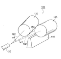
図4は、ロッド素材20に溝を形成するための転造加工装置の概略構成図を示す。図5は、転造加工装置の上面図である。転造加工装置100は、ロッド素材20を挟圧し転造加工するための第1転造ダイス120と第2転造ダイス130、ロッド素材20を支持する基台140を備える。第1転造ダイス120と第2転造ダイス130は、略円柱状の形状を有しており、それぞれの主軸122、132を回転中心として回転する。主軸の長さは、一般的に100〜500mmである。第1転造ダイス120と第2転造ダイス130は、ロッド素材20に溝を形成するため、溝形状を反転した複数の凸条の外周面を有する。第1転造ダイス120と第2転造ダイス130には、ロッド素材20の進入側から退出側に向けて、食い付き部、平行部、逃げ部が形成される。食い付き部では、転造ダイスの端部から平行部に向けて、転造ダイスの外径が漸増する。平行部では、転造ダイスの外径は実質的に等しい。逃げ部では、平行部から転造ダイスの端部に向けて、転造ダイスの外径が漸減する。
FIG. 4 is a schematic configuration diagram of a rolling processing apparatus for forming grooves in the
第1転造ダイス120は、ロッド素材20の軸方向150に対して主軸122の水平方向の閉じ角α1が実質的に0.25°以上0.35°以下となるように配置される。第1転造ダイス120と同様に、第2転造ダイス130は、ロッド素材20の軸方向150に対して主軸132の水平方向の閉じ角α2が実質的に0.25°以上0.35°以下となるように配置される。閉じ角α1と閉じ角α2は、好ましくは同じ角度である。ロッド素材20の軸方向150に対する転造ダイスの主軸の水平方向の閉じ角とは、ロッド素材20の進入側で、(1)主軸122・132と、(2)ロッド素材20の軸方向150と平行で主軸122・132と実質同じ高さの直線とで成す角を意味する。
The first rolling
このため、閉じ角が0.25°を下回ると、実際に転造している時、入口ではロッド素材20が転造ダイス120・130を外側に押し出す状態となる。つまり、一対の転造ダイス120・130が入口で開いた状態、出口で閉じた状態で、ロッド素材20に転造加工が行われる。その結果として、転造ダイス120・130の出口側でのみロッド素材20に転造が行なわれることになる。
For this reason, when the closing angle is less than 0.25 °, the
一方、閉じ角が0.35°を上回ると、転造時も一対の転造ダイス120・130が入口で閉じた状態、出口で開いた状態となる。そのため、転造ダイス120・130の入口側のみでロッド素材20に転造加工が行われることになる。
On the other hand, when the closing angle exceeds 0.35 °, the pair of rolling
図7は、転造加工装置の平面図を示す。ロッド素材20を挟圧する圧力を調整するため、第1転造ダイス120と第2転造ダイス130の間の距離(間隔)X、及び第1転造ダイス120と第2転造ダイス130の主軸とロッド素材20の中心軸22の高さ方向の距離(間隔)Yが調整される。距離Xを調整することにより、一対の転造ダイス120・130のロッド素材20への押し込み量(転造圧)が調整される。距離Yを調整することにより、ワーク高さが調整される。ここでワーク高さとはダイスの主軸122・132を基準とした、ワークの鉛直方向の位置を意味する。
FIG. 7 shows a plan view of the rolling processing apparatus. In order to adjust the pressure with which the
転造加工された塗工用ロッドの表面を研磨装置により、研磨することができる。なお、転造した後に表面を研磨するまでの間に、鍍金その他の表面処理工程が入ってもかまわない。鍍金とは、クロム鍍金やニッケル鍍金、その他複合金属鍍金やダイヤモンドライクカーボン処理などを指し、化学気相成長法やスパッタリング法などによって実施される。図8は研磨装置の断面図を示す。研磨部31、ロッド回転部(不図示)、ロッドシフト部(不図示)を備える。研磨部31は、塗工用ロッド12を上下方向から挟むように保持する多数のラッパ35と、これらラッパ35を保持する保持台36と、ラッパ35と塗工用ロッド12との接触面に研磨剤37を供給する研磨剤供給部38とを備える。 The surface of the coating rod that has been rolled can be polished by a polishing apparatus. In addition, plating and other surface treatment steps may be inserted before the surface is polished after rolling. The plating refers to chromium plating, nickel plating, other composite metal plating, diamond-like carbon treatment, and the like, and is performed by chemical vapor deposition or sputtering. FIG. 8 shows a sectional view of the polishing apparatus. A polishing unit 31, a rod rotating unit (not shown) , and a rod shift unit (not shown) are provided. The polishing unit 31 polishes a large number of trumpet 35 that holds the coating rod 12 so as to sandwich the coating rod 12 from above and below, a holding base 36 that holds these trumpet 35, and a contact surface between the trumpet 35 and the coating rod 12 And an abrasive supply unit 38 for supplying the agent 37.
転造ムラについて、その評価を説明する。図9は塗工用ロッドの外周面の拡大図である。まず、外周表面の山部同士の軸方向に直交する高さの最大値Z1と最小値Z2を求め、最大値Z1と最小値Z2との差Z12を求める。同様に、外周表面の谷部同士の軸方向に直交する高さの最大値Z3と最小値Z4を求め、最大値Z3と最小値Z4との差Z34を求める。差Z12と差Z34の何れか大きい値を転造ムラZ(μm)とした。基準線は、例えば定盤の上に置くことで設定される。この場合、Z4=0となる。 The evaluation of rolling unevenness will be described. FIG. 9 is an enlarged view of the outer peripheral surface of the coating rod. First, the maximum value Z1 and the minimum value Z2 of the height orthogonal to the axial direction of the crests on the outer peripheral surface are obtained, and the difference Z12 between the maximum value Z1 and the minimum value Z2 is obtained. Similarly, the maximum value Z3 and the minimum value Z4 of the height orthogonal to the axial direction of the valleys on the outer peripheral surface are obtained, and the difference Z34 between the maximum value Z3 and the minimum value Z4 is obtained. Any larger value of the difference Z12 and difference Z34 was rolling unevenness Z (μ m). The reference line is set by placing it on a surface plate, for example. In this case, Z4 = 0.

塗工用ロッドの外周面の研磨前に関して、表1によれば、閉じ角を0.25°以上0.35°以下とすることにより、転造ムラが0.3〜0.5(μm)の範囲であった。その結果、スリキズ評価、及び塗布ムラについて、○以上の評価を得た。
For the previous polishing of the outer circumferential surface of the coating rod, according to Table 1, the closing angle by a 0.25 ° or 0.35 ° or less, rolling unevenness 0.3 to 0.5 ([mu] m) Range. As a result, evaluations of ◯ or higher were obtained for scratch evaluation and coating unevenness.
転造後に研磨処理を行なうことで、条件1及び3ではスリキズ評価が1段階向上した。同様に条件4〜6でもスリキズ評価は向上した。しかしながら、条件4〜6について、研磨処理により局所的に溝部の形状が変化することで溝部の断面積のバラつきが増大した。その結果、条件4〜6では塗布ムラが発生した。 By performing the polishing treatment after rolling, the scratch evaluation was improved by one step under conditions 1 and 3 . Similarly, in the conditions 4 to 6 , the scratch evaluation was improved. However, with respect to the conditions 4 to 6 , the variation in the cross-sectional area of the groove portion was increased by locally changing the shape of the groove portion by the polishing treatment. As a result, coating unevenness occurred under conditions 4 to 6 .
Claims (4)
ロッド素材を準備する工程と、
複数の凸条を有する一対の転造ダイスを、前記ロッド素材の軸方向に対して各々の前記転造ダイスの主軸の水平方向の閉じ角が実質的に0.25°以上0.35°以下となるよう配置する工程と、
前記ロッド素材を軸方向に沿って送り出し、前記一対の転造ダイスにより前記ロッド素材を挟圧しながら、主軸を中心に前記一対の転造ダイスを回転させて転造加工する工程と、
を備える塗工用ロッドの製造方法。 A manufacturing method of a coating rod,
Preparing the rod material;
In a pair of rolling dies having a plurality of ridges, the horizontal closing angle of the main axis of each rolling die with respect to the axial direction of the rod material is substantially 0.25 ° to 0.35 °. A step of arranging so that
Sending the rod material along the axial direction, and rolling the pair of rolling dies around the main shaft while pressing the rod material with the pair of rolling dies;
The manufacturing method of the rod for coating provided with.
Priority Applications (3)
| Application Number | Priority Date | Filing Date | Title |
|---|---|---|---|
| JP2010192751A JP5758094B2 (en) | 2010-08-30 | 2010-08-30 | Method for manufacturing coating rod |
| EP20110176923 EP2422899B1 (en) | 2010-08-30 | 2011-08-09 | Method for manufacturing coating rod |
| US13/207,580 US8904840B2 (en) | 2010-08-30 | 2011-08-11 | Method for manufacturing coating rod |
Applications Claiming Priority (1)
| Application Number | Priority Date | Filing Date | Title |
|---|---|---|---|
| JP2010192751A JP5758094B2 (en) | 2010-08-30 | 2010-08-30 | Method for manufacturing coating rod |
Publications (3)
| Publication Number | Publication Date |
|---|---|
| JP2012045614A JP2012045614A (en) | 2012-03-08 |
| JP2012045614A5 true JP2012045614A5 (en) | 2013-03-07 |
| JP5758094B2 JP5758094B2 (en) | 2015-08-05 |
Family
ID=44582353
Family Applications (1)
| Application Number | Title | Priority Date | Filing Date |
|---|---|---|---|
| JP2010192751A Active JP5758094B2 (en) | 2010-08-30 | 2010-08-30 | Method for manufacturing coating rod |
Country Status (3)
| Country | Link |
|---|---|
| US (1) | US8904840B2 (en) |
| EP (1) | EP2422899B1 (en) |
| JP (1) | JP5758094B2 (en) |
Families Citing this family (3)
| Publication number | Priority date | Publication date | Assignee | Title |
|---|---|---|---|---|
| US8739728B2 (en) * | 2011-04-07 | 2014-06-03 | Dynamic Micro Systems, Semiconductor Equipment Gmbh | Methods and apparatuses for roll-on coating |
| CN108097525A (en) * | 2017-12-25 | 2018-06-01 | 五邑大学 | A kind of height-adjustable paint daubs |
| CN112642647B (en) * | 2020-12-09 | 2022-07-22 | 常州方耀自动化科技有限公司 | Coating equipment for processing conductive fabric |
Family Cites Families (12)
| Publication number | Priority date | Publication date | Assignee | Title |
|---|---|---|---|---|
| US412082A (en) * | 1889-10-01 | Apparatus for making spiral screw-threads | ||
| GB443541A (en) * | 1935-09-21 | 1936-03-02 | Timken Roller Bearing Co | An improved process of and means for producing profiled articles of circular section |
| US2243608A (en) * | 1939-08-02 | 1941-05-27 | Werner T Schaurte | Process of making plug gauges |
| GB719821A (en) * | 1952-04-28 | 1954-12-08 | Hans Kruse | Method and apparatus for rolling profiles |
| US3058196A (en) * | 1959-03-09 | 1962-10-16 | Nat Acme Co | Roll head |
| JPH02224840A (en) * | 1988-09-29 | 1990-09-06 | Aisin Seiki Co Ltd | Gear form rolling device |
| JP2676634B2 (en) * | 1989-10-20 | 1997-11-17 | 富士写真フイルム株式会社 | Method for manufacturing coating device rod |
| JP3393822B2 (en) * | 1999-01-22 | 2003-04-07 | オーエスジー株式会社 | Method and apparatus for manufacturing helical rod |
| JP4397071B2 (en) * | 1999-06-18 | 2010-01-13 | 富士フイルム株式会社 | Rod for coating equipment |
| US6708544B2 (en) * | 2001-02-16 | 2004-03-23 | Nsk Ltd. | Thread rolling die and process for the production thereof |
| JP2004089825A (en) * | 2002-08-30 | 2004-03-25 | Osg Corp | Coating rod and its manufacturing method |
| JP4460257B2 (en) * | 2003-10-02 | 2010-05-12 | 富士フイルム株式会社 | Coating rod and manufacturing method thereof |
-
2010
- 2010-08-30 JP JP2010192751A patent/JP5758094B2/en active Active
-
2011
- 2011-08-09 EP EP20110176923 patent/EP2422899B1/en not_active Not-in-force
- 2011-08-11 US US13/207,580 patent/US8904840B2/en not_active Expired - Fee Related
Similar Documents
| Publication | Publication Date | Title |
|---|---|---|
| CN107587086B (en) | A kind of making Nano surface of metal material is modified and the preparation method of nano-micrometre gradient-structure | |
| JP2012045614A5 (en) | ||
| KR102184437B1 (en) | Embossing for electric discharge textured sheets | |
| JP2013099818A (en) | Superfinishing device, superfinishing method, and outer race of bearing with superfinished raceway surface | |
| JP2018526222A (en) | Method for manufacturing a part having a steel core | |
| JP5758094B2 (en) | Method for manufacturing coating rod | |
| JP2005111299A (en) | Coating rod and method for manufacturing the same | |
| JP5610962B2 (en) | Method for manufacturing coating rod | |
| CN100491625C (en) | Bimetal metallurgy combined high precision roller components and manufacturing method thereof | |
| CN207695480U (en) | Bar section of stainless steel shaping diameter-setting equipment | |
| JPH0139849B2 (en) | ||
| JP4196990B2 (en) | Cr-plated mandrel bar for hot seamless pipes and method for producing the same | |
| CN114043328A (en) | Automatic high-efficient production facility of shape chain round pin axle wire rod of preapring for an unfavorable turn of events | |
| EP2500119A2 (en) | Rolling die and method of producing coating rod using the same | |
| JP3288631B2 (en) | Manufacturing method of stainless steel pre-treated steel strip for cold rolling | |
| RU2410185C1 (en) | Procedure for blank rotary smoothing with block of planetary moving rollers | |
| CN111570508B (en) | Frosted surface stainless steel and cold rolling method thereof | |
| CN212399203U (en) | Automatic burnishing device of thin wall tubular product internal diameter | |
| RU2716329C1 (en) | Method of hardening of hard-alloy tool | |
| JP2013507256A (en) | Screw rolling device | |
| CN108326716B (en) | Sheet polishing mechanism driven by drilling machine and polishing method | |
| JPH03234465A (en) | Manufacture of cylinder body and lapping device | |
| CN115283443A (en) | Finishing machine roller and preparation method thereof | |
| JPH1199456A (en) | Finishing-polish method of metal pipe inner surface | |
| GB2520040A (en) | Tablet Tooling surface treatment |