JP2012032094A - Refrigerator-freezer - Google Patents
Refrigerator-freezer Download PDFInfo
- Publication number
- JP2012032094A JP2012032094A JP2010172538A JP2010172538A JP2012032094A JP 2012032094 A JP2012032094 A JP 2012032094A JP 2010172538 A JP2010172538 A JP 2010172538A JP 2010172538 A JP2010172538 A JP 2010172538A JP 2012032094 A JP2012032094 A JP 2012032094A
- Authority
- JP
- Japan
- Prior art keywords
- cooler
- fin
- tube
- refrigerator
- freezer
- Prior art date
- Legal status (The legal status is an assumption and is not a legal conclusion. Google has not performed a legal analysis and makes no representation as to the accuracy of the status listed.)
- Pending
Links
Images


Abstract
Description
本発明は、冷凍サイクルに組み込まれて冷却を行う冷却器を備えた冷凍冷蔵庫に関するものである。 The present invention relates to a refrigerator-freezer provided with a cooler that is incorporated in a refrigeration cycle and cools.
従来の冷凍冷蔵庫の冷却器は、内部に冷媒が流れる伝熱管、及びその伝熱管の管軸方向に互いに間隔をとりながら伝熱管に貫通される形で固定された平板形状フィンからなるフィンアンドチューブ型冷却器と、前記と同様の伝熱管、及びその外周に螺旋状に巻き付けられたフィンからなるスパイラル型冷却器とで構成され、スパイラルフィンチューブ型熱交換器はフィンアンドチューブ型冷却器より風向の上流側に配置されている(例えば、特許文献1参照)。 A conventional refrigerator for a refrigerator is a fin-and-tube comprising a heat transfer tube through which a refrigerant flows and flat plate-like fins fixed in such a manner as to penetrate the heat transfer tube while being spaced apart from each other in the tube axis direction of the heat transfer tube Type cooler, heat transfer tube similar to the above, and a spiral type cooler composed of fins spirally wound around its outer periphery, and the spiral fin tube type heat exchanger has a wind direction higher than that of the fin and tube type cooler. (See, for example, Patent Document 1).
しかしながら、前述した従来の冷凍冷蔵庫では、フィンアンドチューブ型冷却器の風向の上流側に配置されたスパイラルフィンチューブ型熱交換器は、フィンアンドチューブ型冷却器と比較すると非常に高価であった。近年、省エネルギー性が求められているが、それと同時に売価ダウンの影響より原価低減も合わせて求められており、スパイラルフィンチューブ型熱交換器を用いると費用対省エネルギー性効果が薄まってしまい、量産導入が困難なものであった。 However, in the above-described conventional refrigerator-freezer, the spiral fin tube type heat exchanger disposed on the upstream side of the wind direction of the fin and tube type cooler is very expensive compared to the fin and tube type cooler. In recent years, energy savings have been demanded, but at the same time, cost reductions have also been demanded due to the effect of selling prices down, and the use of spiral fin tube heat exchangers has diminished the cost-saving effect and introduced mass production. It was difficult.
本発明は、前述のような課題を解決するためになされたものであり、安価で、熱交換効率の高い冷凍冷蔵庫を提供することを目的とする。 The present invention has been made to solve the above-described problems, and an object thereof is to provide a refrigerator-freezer that is inexpensive and has high heat exchange efficiency.
本発明に係る冷凍冷蔵庫は、流入する冷媒により周囲を冷却する伝熱管、及びその伝熱管に貫通されて固定された複数の平板状フィンより構成された第1のフィンアンドチューブ型冷却器と、流入する冷媒により周囲を冷却する伝熱管、及びその伝熱管に貫通されて固定された複数の平板状フィンより構成された第2のフィンアンドチューブ型冷却器とを備え、第2のフィンアンドチューブ型冷却器は、第1のフィンアンドチューブ型冷却器より小型で、その第1のフィンアンドチューブ型冷却器より空気の流れの上流側に配置されている。 The refrigerator-freezer according to the present invention includes a first fin-and-tube type cooler configured of a heat transfer tube that cools the surroundings with an inflowing refrigerant, and a plurality of plate-like fins that are penetrated and fixed to the heat transfer tube, A second fin and tube comprising a heat transfer tube that cools the surroundings with an inflowing refrigerant, and a second fin-and-tube type cooler composed of a plurality of plate-like fins that are passed through and fixed to the heat transfer tube The mold cooler is smaller than the first fin-and-tube cooler, and is disposed on the upstream side of the air flow from the first fin-and-tube cooler.
本発明においては、第2のフィンアンドチューブ型冷却器を、第1のフィンアンドチューブ型冷却器より空気の流れの上流側に配置したので、冷凍冷蔵庫の動作によって発生する霜の付着箇所が主に第2のフィンアンドチューブ型冷却器となり、第1のフィンアンドチューブ型冷却器への霜の付着量を低下させることが可能になる。これに伴って、第1のフィンアンドチューブ型冷却器の平板状フィン間が霜により閉塞されることがなくなり、気流の熱交換効率の低下を抑えることが可能になり、安価な冷凍冷蔵庫を提供できる。 In the present invention, since the second fin-and-tube cooler is arranged upstream of the air flow from the first fin-and-tube cooler, the location of frost generated by the operation of the refrigerator-freezer is mainly used. It becomes a 2nd fin and tube type cooler, and it becomes possible to reduce the adhesion amount of the frost to the 1st fin and tube type cooler. Accordingly, the flat fins of the first fin-and-tube cooler are not blocked by frost, and it is possible to suppress a reduction in the heat exchange efficiency of the air flow, and provide an inexpensive refrigerator-freezer it can.
実施の形態1.
図1は本発明の実施の形態1に係る冷凍冷蔵庫の正面図、図2は本発明の実施の形態1に係る冷凍冷蔵庫の側面を切断して示す断面図、図3は図2の冷凍冷蔵庫の冷却器室を拡大して示す断面図である。
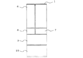
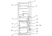
実施の形態1における冷凍冷蔵庫の本体1には、最上段に冷蔵室2が設けられ、その下に切替室3及び製氷室(図示せず)が隣接して設けられ、最下段に野菜室5が設けられ、その上に冷凍室4が設けられている。なお、本体1に設けられた各室の配置は限定されるものではない。冷蔵室2の開口部には、例えば観音式の扉6が取り付けられている。切替室3及び製氷室、冷凍室4、野菜室5の各開口部には、例えば引き出し式の扉7、8,9,10が設けられている。なお、冷蔵室2の扉6を観音式としたが、片開き式の扉でもよい。
Embodiment 1 FIG.
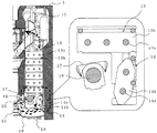
1 is a front view of a refrigerator-freezer according to Embodiment 1 of the present invention, FIG. 2 is a cross-sectional view of the refrigerator-freezer according to Embodiment 1 of the present invention, cut along a side surface, and FIG. 3 is a refrigerator-freezer of FIG. It is sectional drawing which expands and shows the cooler chamber of this.
The main body 1 of the refrigerator-freezer in Embodiment 1 is provided with a refrigeration room 2 at the top, a
本体1の背面の最下部には圧縮機11が設置されている。圧縮機11は、本体1の有する冷凍サイクルを構成する一部品で、冷凍サイクル内の冷媒を圧縮する作用を有している。圧縮機11により圧縮された冷媒は凝縮器(図示せず)で凝縮される。凝縮された状態の冷媒は毛細管(図示せず)によって減圧される。
A
圧縮機11の上方には冷却器室12が設けられている。その冷却器室12には、第1のフィンアンドチューブ型冷却器13(以下、「第1の冷却器13」という)と、第2のフィンアンドチューブ型冷却器14(以下、「第2の冷却器14」という)と、冷却用ファン15と、ラジアントヒーター16と、ヒーターカバー17と、排水孔19を有するドレンパン18と、冷凍室戻り口20と、冷蔵室戻り口21とが設けられている。
A
第1の冷却器13は、伝熱管13aと、伝熱管13aに貫通されて固定された複数の平板状フィン13bより構成されている。第2の冷却器14は、前記と同様に、伝熱管14aと、伝熱管14aに貫通されて固定された複数の平板状フィン14bより構成されている。第2の冷却器14は、図3に示すように、第1の冷却器13より小型で、第1の冷却器13より空気の流れの上流側に配置されている。また、第2の冷却器14の伝熱管14aには、例えば新疎水や親水性の有する物質によってコーティングされている。これは、霜取り時の霜及び水分の保持量を減少させるためである。
The
第1及び第2の冷却器13、14は、本体1の有する冷凍サイクルを構成する一部品で、同一配管にて接続されている。その冷却器13、14は、前述の毛細管により減圧された冷媒を蒸発させ、その蒸発時の吸熱作用により周辺を冷却する。冷却用ファン15は、第1及び第2の冷却器13、14の上方に設けられ、その第1及び第2の冷却器13、14により冷却された冷気を吸引し、本体1の各室に送っている。
The 1st and
ラジアントヒーター16は、第1の冷却器13の下方に配置され、第1及び第2の冷却器13、14に付着した霜を融解する。ヒーターカバー17は、第1の冷却器13とラジアントヒーター16との間に設けられている。そのヒーターカバー17は、ラジアントヒーター16による第1及び第2の冷却器13、14の霜取り時に滴下する水が直接かからないようにするために設けられている。ドレンパン18は、冷却器室12の底部に設けられ、第1及び第2の冷却器13、14から滴下するドレン水を受容する。そのドレン水は、ドレンパン18の底部に設けられた排水孔19から排出される。
The
冷凍室戻り口20は、冷凍室4と冷却器室12の間の風路であり、冷蔵室戻り口21は、冷蔵室2と冷却器室12の間の風路である。冷却用ファン15の運転中は冷凍室4から冷却器室12の方向に冷気が流れる。冷却用ファン15の運転が停止したときには、周辺の温度バランスによって、冷却器室12から冷凍室4へと対流が生じることがある。
The freezer
前記のように構成された冷凍冷蔵庫においては、冷却運転中、第1及び第2の冷却器13、14により冷却された冷気は、冷却用ファン15によって各室に送り込まれ、冷却器室12内に戻る。その冷気の循環により、第1の冷却器13より空気の流れの上流側に配置された第2の冷却器14に霜の付着量が多くなり、第2の冷却器14より下流側に配置された第1の冷却器13には霜の付着量が少なくなる。
In the refrigerator-freezer configured as described above, during the cooling operation, the cold air cooled by the first and
このように、第2の冷却器14を、第1の冷却器13より空気の流れの上流側に配置しているので、第1の冷却器13より第2の冷却器14の方が霜の付着量が多くなる。そのため、第1の冷却器13の平板状フィン13b間が霜により閉塞されることがなくなり、気流の熱交換効率の低下を抑えることが可能になっている。
Thus, since the
また、霜が付着していない冷却運転時においては、第2の冷却器14の追加により、気流の熱交換効率の低下を抑えることができるので、第1及び第2の冷却器13、14全体の熱交換量が増加し、トータルで冷凍冷蔵庫の消費電力量の低減効果が大きくなっている。さらに、第2の冷却器14のフィン14bを平板形状としているので、スパイラルフィンを用いた従来と比べコストの低減を図ることができる。
In addition, during the cooling operation in which frost is not attached, the addition of the
実施の形態2.
図4は本発明の実施の形態2に係る冷凍冷蔵庫の冷却器室を拡大して示す断面図である。なお、実施の形態1と同様の部分には同じ符号を付している。
実施の形態2においては、第2のフィンアンドチューブ型冷却器14(以下、「第2の冷却器14」という)は、図中に示すように、第1のフィンアンドチューブ型冷却器13(以下、「第1の冷却器13」という)より小型で、その第1の冷却器13より空気の流れの上流側に配置されている。また、第2の冷却器14の取付け角度は、第1の冷却器13の平板状フィン13bに対して45度〜90度の範囲内に傾けられている。第2の冷却器14の角度は、冷凍室戻り口20及び冷蔵室戻り口21から冷却器室12内に流入する冷気の風向きに合わせている。
Embodiment 2. FIG.
FIG. 4 is an enlarged cross-sectional view of the refrigerator room of the refrigerator-freezer according to Embodiment 2 of the present invention. In addition, the same code | symbol is attached | subjected to the part similar to Embodiment 1. FIG.
In the second embodiment, the second fin-and-tube cooler 14 (hereinafter, referred to as “second cooler 14”) includes the first fin-and-tube cooler 13 ( Hereinafter, it is smaller than the
これにより、冷却器室12内に流入する冷気と第2の冷却器14の平板状フィン14bとが接触している時間が実施の形態1と比べ長くなる。そのため、第2の冷却器14の熱交換効率がより改善され、第2の冷却器14の平板状フィン14bに付着する霜の量が増加し、省エネルギー性に優れた冷凍冷蔵庫を市場に提供することが可能となる。
As a result, the time during which the cold air flowing into the
実施の形態3.
図5は本発明の実施の形態3に係る冷凍冷蔵庫の冷却器室を拡大して示す断面図である。なお、実施の形態1と同様の部分には同じ符号を付している。
実施の形態3においては、第2のフィンアンドチューブ型冷却器14(以下、「第2の冷却器14」という)は、図中に示すように、第1のフィンアンドチューブ型冷却器13(以下、「第1の冷却器13」という)より小型で、その第1の冷却器13より空気の流れの上流側に配置されている。また、第2の冷却器14の取付け角度は、冷凍室戻り口20及び冷蔵室戻り口21から冷却器室12内に流入する冷気の風向きに合わせるために、第1の冷却器13の平板状フィン13bに対して45度〜90度の範囲内に傾けられている。
FIG. 5 is an enlarged cross-sectional view showing a refrigerator room of a refrigerator-freezer according to
In the third embodiment, the second fin-and-tube cooler 14 (hereinafter referred to as “second cooler 14”) includes a first fin-and-tube cooler 13 ( Hereinafter, it is smaller than the
また、第2の冷却器14に付着する霜は、平板状フィン14bの前縁と冷気が衝突する範囲に成長し易いという現象を踏まえて、平板状フィン14bの前縁面積を拡大している。つまり、平板状フィン14bの形状を例えば八角形形状にして、第2の冷却器14本来の機能である着霜を促進させるようにしている。
これにより、第2の冷却器14の八角形状の平板状フィン14bに付着する霜の量がより増加し、省エネルギー性に優れた冷凍冷蔵庫を市場に提供することが可能となる。
なお、第2の冷却器14の平板状フィン14bの形状を八角形形状としたが、これに限定されるものではない。例えば、その平板状フィン14bの形状は楕円形あるいは三日月形でもよい。
Moreover, the frost adhering to the
Thereby, the quantity of the frost adhering to the octagonal
In addition, although the shape of the
1 本体、2 冷蔵室、3 切替室、4 冷凍室、5 野菜室、6 観音式の扉、7、8,9,10 引き出し式の扉、11 圧縮機、12 冷却器室、13 第1のフィンアンドチューブ型冷却器、13a 伝熱管、13b 平板状フィン、14 第2のフィンアンドチューブ型冷却器、14a 伝熱管、14b 平板状フィン、15 冷却用ファン、16 ラジアントヒーター、17 ヒーターカバー、18 ドレンパン、19 排水孔、20 冷凍室戻り口、21 冷蔵室戻り口。 DESCRIPTION OF SYMBOLS 1 Main body, 2 Refrigeration room, 3 Switching room, 4 Freezing room, 5 Vegetable room, 6 Kannon type door, 7, 8, 9, 10 Pull-out type door, 11 Compressor, 12 Cooler room, 13 1st Fin and tube type cooler, 13a Heat transfer tube, 13b Flat fin, 14 Second fin and tube type cooler, 14a Heat transfer tube, 14b Flat fin, 15 Cooling fan, 16 Radiant heater, 17 Heater cover, 18 Drain pan, 19 drain hole, 20 freezer compartment return, 21 refrigerator compartment return.
Claims (6)
流入する冷媒により周囲を冷却する伝熱管、及び該伝熱管に貫通されて固定された複数の平板状フィンより構成された第2のフィンアンドチューブ型冷却器とを備え、
前記第2のフィンアンドチューブ型冷却器は、前記第1のフィンアンドチューブ型冷却器より小型で、前記第1のフィンアンドチューブ型冷却器より空気の流れの上流側に配置されていることを特徴とする冷凍冷蔵庫。 A first fin-and-tube type cooler composed of a heat transfer tube that cools the surroundings with an inflowing refrigerant, and a plurality of plate-like fins that are passed through and fixed to the heat transfer tube;
A heat transfer tube that cools the surroundings with an inflowing refrigerant, and a second fin-and-tube cooler configured by a plurality of flat fins that are penetrated and fixed to the heat transfer tube,
The second fin-and-tube cooler is smaller than the first fin-and-tube cooler and is arranged upstream of the air flow from the first fin-and-tube cooler. A featured refrigerator-freezer.
Priority Applications (5)
| Application Number | Priority Date | Filing Date | Title |
|---|---|---|---|
| JP2010172538A JP2012032094A (en) | 2010-07-30 | 2010-07-30 | Refrigerator-freezer |
| TW100108474A TWI414738B (en) | 2010-07-30 | 2011-03-14 | Freezer-refrigerator |
| SG2011020807A SG177809A1 (en) | 2010-07-30 | 2011-03-23 | Freezer-refrigerator |
| CN201110094838.8A CN102345957B (en) | 2010-07-30 | 2011-04-15 | Freezing and refrigerating chamber |
| HK12104597.5A HK1163796A1 (en) | 2010-07-30 | 2012-05-10 | Freezer-refrigerator |
Applications Claiming Priority (1)
| Application Number | Priority Date | Filing Date | Title |
|---|---|---|---|
| JP2010172538A JP2012032094A (en) | 2010-07-30 | 2010-07-30 | Refrigerator-freezer |
Publications (2)
| Publication Number | Publication Date |
|---|---|
| JP2012032094A true JP2012032094A (en) | 2012-02-16 |
| JP2012032094A5 JP2012032094A5 (en) | 2012-08-30 |
Family
ID=45544854
Family Applications (1)
| Application Number | Title | Priority Date | Filing Date |
|---|---|---|---|
| JP2010172538A Pending JP2012032094A (en) | 2010-07-30 | 2010-07-30 | Refrigerator-freezer |
Country Status (5)
| Country | Link |
|---|---|
| JP (1) | JP2012032094A (en) |
| CN (1) | CN102345957B (en) |
| HK (1) | HK1163796A1 (en) |
| SG (1) | SG177809A1 (en) |
| TW (1) | TWI414738B (en) |
Cited By (3)
| Publication number | Priority date | Publication date | Assignee | Title |
|---|---|---|---|---|
| JP2012042192A (en) * | 2011-05-24 | 2012-03-01 | Mitsubishi Electric Corp | Refrigerator |
| WO2017002768A1 (en) * | 2015-06-30 | 2017-01-05 | 三菱電機株式会社 | Refrigerator |
| JP2018036010A (en) * | 2016-09-01 | 2018-03-08 | アクア株式会社 | refrigerator |
Citations (3)
| Publication number | Priority date | Publication date | Assignee | Title |
|---|---|---|---|---|
| JPS57139263A (en) * | 1981-02-23 | 1982-08-28 | Fuji Electric Co Ltd | Cooler for open showcase |
| JPH1114191A (en) * | 1997-06-20 | 1999-01-22 | Matsushita Refrig Co Ltd | Heat exchanger |
| JPH11264632A (en) * | 1998-03-19 | 1999-09-28 | Sanyo Electric Co Ltd | Heat exchanger and manufacture thereof |
Family Cites Families (3)
| Publication number | Priority date | Publication date | Assignee | Title |
|---|---|---|---|---|
| JP4459145B2 (en) * | 2005-09-26 | 2010-04-28 | 株式会社東芝 | refrigerator |
| CN2847176Y (en) * | 2005-11-30 | 2006-12-13 | 海信集团有限公司 | Integrated energy saving silencing refrigerator refrigeration system |
| JP4950906B2 (en) * | 2008-01-17 | 2012-06-13 | 株式会社東芝 | refrigerator |
-
2010
- 2010-07-30 JP JP2010172538A patent/JP2012032094A/en active Pending
-
2011
- 2011-03-14 TW TW100108474A patent/TWI414738B/en not_active IP Right Cessation
- 2011-03-23 SG SG2011020807A patent/SG177809A1/en unknown
- 2011-04-15 CN CN201110094838.8A patent/CN102345957B/en active Active
-
2012
- 2012-05-10 HK HK12104597.5A patent/HK1163796A1/en unknown
Patent Citations (3)
| Publication number | Priority date | Publication date | Assignee | Title |
|---|---|---|---|---|
| JPS57139263A (en) * | 1981-02-23 | 1982-08-28 | Fuji Electric Co Ltd | Cooler for open showcase |
| JPH1114191A (en) * | 1997-06-20 | 1999-01-22 | Matsushita Refrig Co Ltd | Heat exchanger |
| JPH11264632A (en) * | 1998-03-19 | 1999-09-28 | Sanyo Electric Co Ltd | Heat exchanger and manufacture thereof |
Cited By (4)
| Publication number | Priority date | Publication date | Assignee | Title |
|---|---|---|---|---|
| JP2012042192A (en) * | 2011-05-24 | 2012-03-01 | Mitsubishi Electric Corp | Refrigerator |
| WO2017002768A1 (en) * | 2015-06-30 | 2017-01-05 | 三菱電機株式会社 | Refrigerator |
| JP6121076B1 (en) * | 2015-06-30 | 2017-04-26 | 三菱電機株式会社 | refrigerator |
| JP2018036010A (en) * | 2016-09-01 | 2018-03-08 | アクア株式会社 | refrigerator |
Also Published As
| Publication number | Publication date |
|---|---|
| TW201205018A (en) | 2012-02-01 |
| SG177809A1 (en) | 2012-02-28 |
| CN102345957A (en) | 2012-02-08 |
| CN102345957B (en) | 2015-01-14 |
| TWI414738B (en) | 2013-11-11 |
| HK1163796A1 (en) | 2012-09-14 |
Similar Documents
| Publication | Publication Date | Title |
|---|---|---|
| JP4895958B2 (en) | refrigerator | |
| JP2008202823A (en) | Refrigerator | |
| KR20030004899A (en) | Refrigerator with condenser and backcover in one | |
| JP5847198B2 (en) | refrigerator | |
| JP5369157B2 (en) | Freezer refrigerator | |
| JP2011158250A (en) | Heat exchanger and refrigerator-freezer mounted with the heat exchanger | |
| JP2012032094A (en) | Refrigerator-freezer | |
| JP2018071874A (en) | refrigerator | |
| CN104823010A (en) | Refrigerator | |
| JP2014137166A (en) | Radiation type air conditioner | |
| CN113803941B (en) | Air duct structure, refrigerating unit, control method and storage medium | |
| JP2020133933A (en) | Defrosting device and refrigerator including the same | |
| JP2010230212A (en) | Refrigerator | |
| JP6490221B2 (en) | refrigerator | |
| JP2018048799A (en) | refrigerator | |
| JP5020159B2 (en) | Heat exchanger, refrigerator and air conditioner | |
| JP2003314947A (en) | Heat exchanger unit and refrigerator | |
| CN112113381A (en) | Refrigerator with special-shaped evaporator | |
| JP2011080692A (en) | Refrigerator | |
| JP2012087952A (en) | Refrigerator freezer | |
| JP4837068B2 (en) | Freezer refrigerator | |
| JP2019027649A (en) | refrigerator | |
| WO2023063165A1 (en) | Refrigerator | |
| JP2012013269A (en) | Heat exchanger, refrigerating cycle device using the same, air conditioner using the refrigerating cycle device, and heat pump hot water supply machine | |
| JP2003121085A (en) | Heat exchanger, heat exchange unit, and cooling storage |
Legal Events
| Date | Code | Title | Description |
|---|---|---|---|
| A521 | Written amendment |
Free format text: JAPANESE INTERMEDIATE CODE: A523 Effective date: 20120711 |
|
| A621 | Written request for application examination |
Free format text: JAPANESE INTERMEDIATE CODE: A621 Effective date: 20120711 |
|
| A977 | Report on retrieval |
Free format text: JAPANESE INTERMEDIATE CODE: A971007 Effective date: 20121217 |
|
| A131 | Notification of reasons for refusal |
Free format text: JAPANESE INTERMEDIATE CODE: A131 Effective date: 20130108 |
|
| A02 | Decision of refusal |
Free format text: JAPANESE INTERMEDIATE CODE: A02 Effective date: 20130514 |