JP2012024979A - Plate cylinder, printing apparatus, and method of forming plate cylinder - Google Patents
Plate cylinder, printing apparatus, and method of forming plate cylinder Download PDFInfo
- Publication number
- JP2012024979A JP2012024979A JP2010163993A JP2010163993A JP2012024979A JP 2012024979 A JP2012024979 A JP 2012024979A JP 2010163993 A JP2010163993 A JP 2010163993A JP 2010163993 A JP2010163993 A JP 2010163993A JP 2012024979 A JP2012024979 A JP 2012024979A
- Authority
- JP
- Japan
- Prior art keywords
- cylindrical member
- pattern forming
- pattern
- plate cylinder
- plate
- Prior art date
- Legal status (The legal status is an assumption and is not a legal conclusion. Google has not performed a legal analysis and makes no representation as to the accuracy of the status listed.)
- Pending
Links
Images


Classifications
-
- B—PERFORMING OPERATIONS; TRANSPORTING
- B41—PRINTING; LINING MACHINES; TYPEWRITERS; STAMPS
- B41F—PRINTING MACHINES OR PRESSES
- B41F13/00—Common details of rotary presses or machines
- B41F13/08—Cylinders
- B41F13/10—Forme cylinders
-
- B—PERFORMING OPERATIONS; TRANSPORTING
- B41—PRINTING; LINING MACHINES; TYPEWRITERS; STAMPS
- B41C—PROCESSES FOR THE MANUFACTURE OR REPRODUCTION OF PRINTING SURFACES
- B41C1/00—Forme preparation
- B41C1/02—Engraving; Heads therefor
- B41C1/025—Engraving; Heads therefor characterised by means for the liquid etching of substrates for the manufacturing of relief or intaglio printing forms, already provided with resist pattern
-
- B—PERFORMING OPERATIONS; TRANSPORTING
- B29—WORKING OF PLASTICS; WORKING OF SUBSTANCES IN A PLASTIC STATE IN GENERAL
- B29C—SHAPING OR JOINING OF PLASTICS; SHAPING OF MATERIAL IN A PLASTIC STATE, NOT OTHERWISE PROVIDED FOR; AFTER-TREATMENT OF THE SHAPED PRODUCTS, e.g. REPAIRING
- B29C59/00—Surface shaping of articles, e.g. embossing; Apparatus therefor
- B29C59/02—Surface shaping of articles, e.g. embossing; Apparatus therefor by mechanical means, e.g. pressing
- B29C59/04—Surface shaping of articles, e.g. embossing; Apparatus therefor by mechanical means, e.g. pressing using rollers or endless belts
-
- B—PERFORMING OPERATIONS; TRANSPORTING
- B41—PRINTING; LINING MACHINES; TYPEWRITERS; STAMPS
- B41F—PRINTING MACHINES OR PRESSES
- B41F3/00—Cylinder presses, i.e. presses essentially comprising at least one cylinder co-operating with at least one flat type-bed
- B41F3/18—Cylinder presses, i.e. presses essentially comprising at least one cylinder co-operating with at least one flat type-bed of special construction or for particular purposes
- B41F3/36—Cylinder presses, i.e. presses essentially comprising at least one cylinder co-operating with at least one flat type-bed of special construction or for particular purposes for intaglio or heliogravure printing
-
- B—PERFORMING OPERATIONS; TRANSPORTING
- B41—PRINTING; LINING MACHINES; TYPEWRITERS; STAMPS
- B41N—PRINTING PLATES OR FOILS; MATERIALS FOR SURFACES USED IN PRINTING MACHINES FOR PRINTING, INKING, DAMPING, OR THE LIKE; PREPARING SUCH SURFACES FOR USE AND CONSERVING THEM
- B41N1/00—Printing plates or foils; Materials therefor
- B41N1/04—Printing plates or foils; Materials therefor metallic
- B41N1/06—Printing plates or foils; Materials therefor metallic for relief printing or intaglio printing
-
- B—PERFORMING OPERATIONS; TRANSPORTING
- B41—PRINTING; LINING MACHINES; TYPEWRITERS; STAMPS
- B41N—PRINTING PLATES OR FOILS; MATERIALS FOR SURFACES USED IN PRINTING MACHINES FOR PRINTING, INKING, DAMPING, OR THE LIKE; PREPARING SUCH SURFACES FOR USE AND CONSERVING THEM
- B41N1/00—Printing plates or foils; Materials therefor
- B41N1/12—Printing plates or foils; Materials therefor non-metallic other than stone, e.g. printing plates or foils comprising inorganic materials in an organic matrix
Landscapes
- Engineering & Computer Science (AREA)
- Mechanical Engineering (AREA)
- Manufacturing & Machinery (AREA)
- Printing Plates And Materials Therefor (AREA)
- Manufacture Or Reproduction Of Printing Formes (AREA)
- Electroluminescent Light Sources (AREA)
Abstract
Description
本発明は版胴、印刷装置及び版胴の成形方法についての技術分野に関する。詳しくは、微細加工によって印刷用の所定のパターンが形成されたパターン形成板を円筒部材の外周面に巻き付けて接合し、製造コストの高騰を来たすことなく精密な印刷用のパターンを形成する技術分野に関する。 The present invention relates to a technical field of a plate cylinder, a printing apparatus, and a method for forming a plate cylinder. Specifically, a technical field in which a pattern forming plate on which a predetermined pattern for printing is formed by microfabrication is wound around and joined to the outer peripheral surface of a cylindrical member to form a precise pattern for printing without causing an increase in manufacturing cost. About.
液晶ディスプレイ(Liquid Crystal Display:LCD )、プラズマディスプレイパネル(Plasma Display Panel:PDP)、EL(Electro Luminescence)ディスプレイ等のフラットパネルディスプレイ(ガラス基板)に対して微細な配線パターンを形成する装置がある。 There is an apparatus that forms a fine wiring pattern on a flat panel display (glass substrate) such as a liquid crystal display (LCD), a plasma display panel (PDP), and an EL (Electro Luminescence) display.
このような装置には、半導体の製造工程であるフォトリソグラフィー技術やエッチング技術を応用したものがあるが、これらの装置は高度な露光部を備えたり真空技術を使用するため複雑な構成とされている。 Some of these devices apply photolithography technology and etching technology, which are semiconductor manufacturing processes, but these devices have complicated structures because they are equipped with advanced exposure parts or use vacuum technology. Yes.
そこで、近年、印刷により微細な配線パターンを形成するプリンタブルエレクトロニクス技術を用いた印刷装置が開発されている。 Therefore, in recent years, printing apparatuses using printable electronics technology for forming fine wiring patterns by printing have been developed.
プリンタブルエレクトロニクス技術を用いた印刷装置には、例えば、グラビアオフセット印刷を行う装置があり、このような印刷装置においては、外周面に所定のパターンが形成された円筒状の版胴が回転されブランケットロールを介して被印刷物に対してインクが転写されて印刷が行われる。 Printing apparatuses using printable electronics technology include, for example, an apparatus that performs gravure offset printing. In such a printing apparatus, a cylindrical plate cylinder having a predetermined pattern formed on its outer peripheral surface is rotated to blanket rolls. The ink is transferred to the printing material through the printing, and printing is performed.
版胴は、一般に、円筒状のガラス部材の外周面に配線パターンを形成するための印刷用の所定のパターンが形成されて成る(例えば、特許文献1参照)。版胴のパターンは、版胴となる円筒状の母材の外周面にレジストを塗布し、塗布したレジストを露光、現像、加熱硬化することにより形成される。 The plate cylinder is generally formed by forming a predetermined pattern for printing on the outer peripheral surface of a cylindrical glass member (see, for example, Patent Document 1). The pattern of the plate cylinder is formed by applying a resist to the outer peripheral surface of a cylindrical base material that becomes the plate cylinder, and exposing, developing, and heat-curing the applied resist.
ところで、近年、液晶ディスプレイ等に用いられるガラス基板は大型化の傾向にあるが、配線パターンの印刷精度として1μm〜数μm程度の高い印刷精度が要求される。 By the way, in recent years, glass substrates used for liquid crystal displays and the like tend to be enlarged, but high printing accuracy of about 1 μm to several μm is required as wiring pattern printing accuracy.
ところが、上記したように、版胴となる円筒状の母材の外周面にレジストを塗布して露光等を行うことにより配線パターンを形成する方法にあっては、レジストを円周状の表面に塗布するため、レジストの均一性を確保することが容易ではなく、パターンの加工精度が低下し易いと言う問題がある。 However, as described above, in the method of forming a wiring pattern by applying a resist to the outer peripheral surface of a cylindrical base material that becomes a plate cylinder and performing exposure or the like, the resist is applied to the circumferential surface. Since it is applied, it is not easy to ensure the uniformity of the resist, and there is a problem that the processing accuracy of the pattern tends to be lowered.
また、円筒状の表面に対して露光や現像を行うことも困難な作業であり、製造コストも高くなってしまうと言う問題もある。 In addition, it is difficult to perform exposure and development on the cylindrical surface, and there is a problem that the manufacturing cost is increased.
そこで、本発明版胴、印刷装置及び版胴の成形方法は、上記した問題点を克服し、製造コストの高騰を来たすことなく精密な印刷用のパターンを形成することを課題とする。 Accordingly, it is an object of the present invention to overcome the above-described problems and form a precise printing pattern without increasing the manufacturing cost.
版胴は、上記した課題を解決するために、円筒部材と、平板状の基板に微細加工によって印刷用の所定のパターンが形成されて成るパターン形成板とを備え、前記パターン形成板が屈曲され前記円筒部材の外周面に巻き付けられて接合されることにより構成されたものである。 In order to solve the above-described problems, the plate cylinder includes a cylindrical member and a pattern forming plate in which a predetermined pattern for printing is formed by fine processing on a flat substrate, and the pattern forming plate is bent. It is configured by being wound around and joined to the outer peripheral surface of the cylindrical member.
従って、版胴にあっては、印刷用のパターンが平板状の基板に微細加工によって形成される。 Therefore, in the plate cylinder, a printing pattern is formed on a flat substrate by fine processing.
上記した版胴においては、前記円筒部材と前記パターン形成板がガラス材料によって形成されることが望ましい。 In the plate cylinder described above, it is desirable that the cylindrical member and the pattern forming plate are formed of a glass material.
円筒部材とパターン形成板がガラス材料によって形成されることにより、円筒部材とパターン形成板の熱膨張係数が小さくなる。 By forming the cylindrical member and the pattern forming plate from a glass material, the thermal expansion coefficients of the cylindrical member and the pattern forming plate are reduced.
上記した版胴においては、前記円筒部材と前記パターン形成板が同じ材料によって形成されることが望ましい。 In the plate cylinder described above, it is desirable that the cylindrical member and the pattern forming plate are formed of the same material.
円筒部材とパターン形成板が同じ材料によって形成されることにより、円筒部材とパターン形成板の熱膨張係数が同じになる。 By forming the cylindrical member and the pattern forming plate from the same material, the thermal expansion coefficients of the cylindrical member and the pattern forming plate are the same.
上記した版胴においては、前記基板をエッチングすることにより厚みを薄くして前記パターン形成板を成形することが望ましい。 In the plate cylinder described above, it is desirable that the pattern forming plate be formed by reducing the thickness by etching the substrate.
基板をエッチングすることにより厚みを薄くしてパターン形成板を成形することにより、基板がエッチングされて薄型化される。 The substrate is etched and thinned by forming the pattern forming plate by reducing the thickness by etching the substrate.
上記した版胴においては、前記パターン形成板を、剥離剤の添加、紫外線の照射又は加熱若しくは冷却により接着力が低下する接着剤によって前記円筒部材の外周面に接合することが望ましい。 In the plate cylinder described above, it is desirable that the pattern forming plate be bonded to the outer peripheral surface of the cylindrical member with an adhesive whose adhesive strength is reduced by adding a release agent, irradiating ultraviolet rays, or heating or cooling.
パターン形成板を、剥離剤の添加、紫外線の照射又は加熱若しくは冷却により接着力が低下する接着剤によって前記円筒部材の外周面に接合することにより、接着剤に対して剥離剤の添加、紫外線の照射、加熱又は冷却を行うことによりパターン形成板が円筒部材から剥離可能とされる。 The pattern forming plate is bonded to the outer peripheral surface of the cylindrical member with an adhesive whose adhesive strength is reduced by addition of a release agent, irradiation of ultraviolet rays, or heating or cooling. By performing irradiation, heating or cooling, the pattern forming plate can be peeled from the cylindrical member.
上記した版胴においては、前記所定のパターンが前記円筒部材の外周面に連通された複数の凹部によって形成され、前記凹部に充填されるインクに対して前記パターン形成板の付着力が前記円筒部材の付着力より小さくされることが望ましい。 In the plate cylinder described above, the predetermined pattern is formed by a plurality of recesses communicating with the outer peripheral surface of the cylindrical member, and the adhesion force of the pattern forming plate to the ink filled in the recess is the cylindrical member. It is desirable to make it smaller than the adhesion force.
所定のパターンの凹部に充填されるインクに対してパターン形成板の付着力が円筒部材の付着力より小さくされることにより、版胴からのインクの転写性が向上する。 By making the adhesive force of the pattern forming plate smaller than the adhesive force of the cylindrical member with respect to the ink filled in the concave portion of the predetermined pattern, the transferability of the ink from the plate cylinder is improved.
印刷装置は、上記した課題を解決するために、円筒部材と、平板状の基板に微細加工によって印刷用の所定のパターンが形成されて成るパターン形成板とを有し、前記パターン形成板が屈曲され前記円筒部材の外周面に巻き付けられて接合されることにより構成された版胴を備え、前記版胴が回転されることにより被印刷物に対して印刷を行ったものである。 In order to solve the above-described problems, the printing apparatus includes a cylindrical member and a pattern forming plate in which a predetermined pattern for printing is formed on a flat substrate by fine processing, and the pattern forming plate is bent. And a printing drum formed by being wound around and joined to the outer peripheral surface of the cylindrical member, and printing is performed on the printing object by rotating the printing drum.
従って、印刷装置にあっては、印刷用のパターンが平板状の基板に微細加工によって形成される。 Therefore, in the printing apparatus, a printing pattern is formed on a flat substrate by fine processing.
版胴の成形方法は、上記した課題を解決するために、平板状の基板に微細加工によって印刷用の所定のパターンを形成してパターン形成板を成形し、円筒部材の外周面に前記パターン形成板を屈曲させ巻き付けて接合して成形したものである。 In order to solve the above-described problems, the plate cylinder forming method forms a predetermined pattern for printing on a flat substrate by fine processing to form a pattern forming plate, and forms the pattern on the outer peripheral surface of the cylindrical member. A plate is bent and wound and joined to form.
従って、版胴の成形方法にあっては、平板状の基板に微細加工によって形成された印刷用のパターンを有するパターン形成板が円筒部材の外周面に巻き付けられる。 Therefore, in the method of forming a plate cylinder, a pattern forming plate having a printing pattern formed on a flat substrate by fine processing is wound around the outer peripheral surface of the cylindrical member.
本発明版胴は、円筒部材と、平板状の基板に微細加工によって印刷用の所定のパターンが形成されて成るパターン形成板とを備え、前記パターン形成板が屈曲され前記円筒部材の外周面に巻き付けられて接合されることにより構成されている。 The plate cylinder of the present invention includes a cylindrical member, and a pattern forming plate formed by forming a predetermined pattern for printing on a flat substrate by fine processing, and the pattern forming plate is bent on the outer peripheral surface of the cylindrical member. It is configured by being wound and joined.
従って、平板状の基板に印刷用のパターンを形成すればよく、円筒状の母材の外周面に印刷用のパターンを形成する必要がないため、製造コストの高騰を来たすことなく精密な印刷用のパターンを形成することができる。 Therefore, it is only necessary to form a printing pattern on a flat substrate, and it is not necessary to form a printing pattern on the outer peripheral surface of the cylindrical base material. Therefore, for precise printing without increasing the manufacturing cost. The pattern can be formed.
請求項2に記載した発明にあっては、前記円筒部材と前記パターン形成板がガラス材料によって形成されている。
In the invention described in
従って、温度変化による膨張及び収縮を抑制して加工精度の向上及びパターンの精密な精度を確保することができると共にパターン形成板の破損や割れの抑制を図ることができる。 Therefore, expansion and contraction due to temperature changes can be suppressed to improve processing accuracy and ensure the accuracy of the pattern, and it is possible to suppress damage and cracking of the pattern forming plate.
請求項3に記載した発明にあっては、前記円筒部材と前記パターン形成板が同じ材料によって形成されている。 In the invention described in claim 3, the cylindrical member and the pattern forming plate are formed of the same material.
従って、円筒部材とパターン形成板の熱膨張係数が同じにされ、円筒部材とパターン形成板において温度変化による膨張率及び収縮率の差異が生じなくなるため、加工精度の向上及び歩留まりの低下を図ることができる。 Accordingly, the thermal expansion coefficients of the cylindrical member and the pattern forming plate are made the same, and the difference between the expansion rate and the shrinkage rate due to temperature change does not occur between the cylindrical member and the pattern forming plate, so that the processing accuracy is improved and the yield is reduced. Can do.
請求項4に記載した発明にあっては、前記基板をエッチングすることにより厚みを薄くして前記パターン形成板を成形している。
In the invention described in
従って、パターン形成板の成形及び薄型化を容易に行うことができる共にパターン形成板の厚みに関し設計の自由度の向上を図ることができる。 Therefore, the pattern forming plate can be easily formed and thinned, and the degree of design freedom can be improved with respect to the thickness of the pattern forming plate.
請求項5に記載した発明にあっては、前記パターン形成板を、剥離剤の添加、紫外線の照射又は加熱若しくは冷却により接着力が低下する接着剤によって前記円筒部材の外周面に接合している。
In the invention described in
従って、パターン形成板に破損や損傷が生じたときに、版胴の交換を行う必要がなく、パターン形成板のみを交換すればよく、版胴による印刷作業におけるコストの低減を図ることができる。 Therefore, when the pattern forming plate is broken or damaged, it is not necessary to replace the plate cylinder, and only the pattern forming plate needs to be replaced, and the cost for printing work using the plate cylinder can be reduced.
請求項6に記載した発明にあっては、前記所定のパターンが前記円筒部材の外周面に連通された複数の凹部によって形成され、前記凹部に充填されるインクに対して前記パターン形成板の付着力が前記円筒部材の付着力より小さくされている。
In the invention described in
従って、版胴からのインクの良好な転写性が確保され、被印刷物に対する良好な印刷精度を確保することができる。 Therefore, good transferability of ink from the plate cylinder is ensured, and good printing accuracy for the printing material can be ensured.
本発明印刷装置は、円筒部材と、平板状の基板に微細加工によって印刷用の所定のパターンが形成されて成るパターン形成板とを有し、前記パターン形成板が屈曲され前記円筒部材の外周面に巻き付けられて接合されることにより構成された版胴を備え、前記版胴が回転されることにより被印刷物に対して印刷を行っている。 The printing apparatus of the present invention has a cylindrical member and a pattern forming plate formed by forming a predetermined pattern for printing on a flat substrate by fine processing, and the outer peripheral surface of the cylindrical member is bent by the pattern forming plate. And a printing cylinder formed by being wound around and bonded to each other, and printing is performed on the substrate by rotating the printing cylinder.
従って、平板状の基板に印刷用のパターンを形成すればよく、円筒状の母材の外周面に印刷用のパターンを形成する必要がないため、製造コストの高騰を来たすことなく精密な印刷用のパターンを形成することができる。 Therefore, it is only necessary to form a printing pattern on a flat substrate, and it is not necessary to form a printing pattern on the outer peripheral surface of the cylindrical base material. Therefore, for precise printing without increasing the manufacturing cost. The pattern can be formed.
本発明版胴の成形方法は、平板状の基板に微細加工によって印刷用の所定のパターンを形成してパターン形成板を成形し、円筒部材の外周面に前記パターン形成板を屈曲させ巻き付けて接合して成形している。 According to the present invention, the plate cylinder is formed by forming a predetermined pattern for printing on a flat substrate by fine processing to form a pattern forming plate, and bending and winding the pattern forming plate around the outer peripheral surface of a cylindrical member. And molded.
従って、平板状の基板に印刷用のパターンを形成すればよく、円筒状の母材の外周面に印刷用のパターンを形成する必要がないため、製造コストの高騰を来たすことなく精密な印刷用のパターンを形成することができる。 Therefore, it is only necessary to form a printing pattern on a flat substrate, and it is not necessary to form a printing pattern on the outer peripheral surface of the cylindrical base material. Therefore, for precise printing without increasing the manufacturing cost. The pattern can be formed.
以下に、本発明版胴、印刷装置及び版胴の成形方法の実施の形態を添付図面を参照して説明する。 Embodiments of a plate cylinder, a printing apparatus, and a plate cylinder forming method of the present invention will be described below with reference to the accompanying drawings.
以下に示した最良の形態は、本発明印刷装置をグラビアオフセット印刷を行う印刷装置に適用し、本発明版胴をグラビアオフセット印刷を行う印刷装置に設けられる版胴に適用し、本発明版胴の成形方法をグラビアオフセット印刷を行う印刷装置に設けられる版胴の成形方法に適用したものである。 In the best mode shown below, the printing apparatus of the present invention is applied to a printing apparatus that performs gravure offset printing, the plate cylinder of the present invention is applied to a plate cylinder provided in a printing apparatus that performs gravure offset printing, and the plate cylinder of the present invention is applied. Is applied to a plate cylinder forming method provided in a printing apparatus that performs gravure offset printing.
尚、本発明版胴、印刷装置及び版胴の成形方法の適用範囲はそれぞれグラビアオフセット印刷を行う印刷装置、この印刷装置に設けられる版胴及びこの版胴の成形方法に限られることはない。本発明印刷装置、版胴及び版胴の成形方法は、版胴の回転により印刷を行う各種の印刷装置、これらの各種の印刷装置に設けられる版胴及びこれらの版胴の成形方法に広く適用することができる。 The scope of application of the plate cylinder, printing apparatus, and plate cylinder forming method of the present invention is not limited to a printing apparatus that performs gravure offset printing, a plate cylinder provided in the printing apparatus, and a method for forming the plate cylinder. The printing apparatus, plate cylinder, and plate cylinder forming method of the present invention are widely applied to various printing apparatuses that perform printing by rotating the plate cylinder, plate cylinders provided in these various printing apparatuses, and methods for forming these plate cylinders. can do.
以下の説明にあっては、例として、ガラス基板等の被印刷物が上下方向を向く向きで配置された状態で方向を示すが、本発明の実施に関しては、これらの方向に限定されることはない。 In the following description, as an example, the direction in which the substrate such as a glass substrate is arranged in a direction facing the up-down direction is shown, but the implementation of the present invention is limited to these directions. Absent.
[印刷装置の構成]
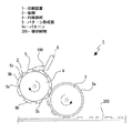
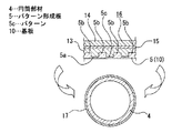
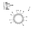
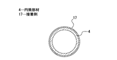
印刷装置1は、円筒状の版胴2と版胴2の回転に伴って回転されるブランケットロール3とを備えている(図1参照)。
[Configuration of printing device]
The
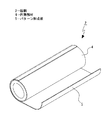
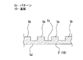
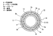
版胴2は円筒部材4と円筒部材4の外周面に巻き付けられて接着剤によって接合されたパターン形成板5とから成る(図1及び図2参照)。
The
円筒部材4は、例えば、石英ガラス等のガラス材料によって形成されている。
The
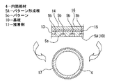
パターン形成板5は円筒部材と同じ材料、例えば、石英ガラス等のガラス材料によって形成されている。パターン形成板5は円筒部材4側に位置するベース部5aとベース部5aから外方へ突出された複数の突部5b、5b、・・・とによって構成され、突部5b、5b、・・・間の複数の凹部によって所定のパターン5cが形成される。
The
パターン5cの各凹部には印刷用のインク100が充填される。インク100は図示しないインク供給装置から供給されてパターン5cの各凹部に充填され、不要なインク100はブレード6によって掻き取られる。
尚、円筒部材4とパターン形成板5は同じ材料であることが望ましいが、熱膨張係数が略同じであれば異なる材料によって形成することも可能である。また、円筒部材4とパターン形成板5の熱膨張係数は同じであることが望ましく、円筒部材4とパターン形成板5をガラス材料以外の他の材料、例えば、金属材料やセラミック材料によって形成することも可能である。
The
但し、円筒部材4とパターン形成板5は熱膨張係数が低い材料によって形成されることがより望ましく、低い熱膨張係数を確保すると共に破損や割れを生じ難い材料としてガラス材料を用いることが最適である。円筒部材4とパターン形成板5がガラス材料によって形成されることにより、温度変化による膨張及び収縮を抑制して加工精度の向上及びパターン5cの精密な精度を確保することができると共にパターン形成板5の破損や割れの抑制を図ることができる。
However, it is more desirable that the
また、円筒部材4とパターン形成板5が同じ材料によって形成されることにより、円筒部材4とパターン形成板5の熱膨張係数が同じにされ、円筒部材4とパターン形成板5において温度変化による膨張率及び収縮率の差異が生じなくなるため、加工精度の向上及び歩留まりの低下を図ることができる。
Further, since the
ブランケットロール3は円筒状に形成され、外周部にゴム等の材料によって形成された転写部3aを有している。ブランケットロール3は版胴2の回転に伴って回転され、版胴2と同じ角速度で回転される。ブランケットロール3が回転されると、版胴2におけるパターン5cの各凹部に充填されたインク100が転写部3aに受理される。
The blanket roll 3 is formed in a cylindrical shape, and has a
版胴2とブランケットロール3とブレード6は上下方向及び左右方向(印刷方向)へ一体になって移動可能とされている。
The
被印刷物200は、例えば、液晶ディスプレイ等に用いられる透明なガラス板であり、被印刷物200に対して印刷装置1によって配線パターンが印刷される。尚、被印刷物200としては、例えば、樹脂や金属によって形成された平板状の部材を用いることも可能である。但し、被印刷物200としては版胴2及びブランケットロール3と同一材料又は熱膨張係数が略同じである材料を用いることが望ましく、特に、熱膨張係数が低いガラス材料を用いることがより望ましい。
The
上記のように構成された印刷装置1において、パターン5cの各凹部にインク100が充填された版胴2が回転されると、ブランケットロール3が版胴2の回転に伴って回転されると共に一体になって印刷方向(左方)へ移動される。
In the
版胴2とブランケットロール3の回転に伴ってインク100がブランケットロール3に受理され、ブランケットロール3に受理されたインク100が被印刷物200に転写されて印刷パターンが形成される。
As the
尚、上記には、印刷装置1の構成としてブランケットロール3を有するオフセット印刷用の装置を例として示したが、印刷装置としては、ブランケットロール3を有しないオフセット印刷用以外の装置であってもよい。
In the above description, the offset printing apparatus having the blanket roll 3 is shown as an example of the configuration of the
[版胴の成形方法]
以下に、版胴2の成形方法について説明する(図3乃至図17参照)。
[Method of forming plate cylinder]
Below, the shaping | molding method of the
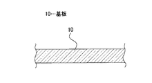
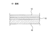
先ず、パターン形成板5を成形するための基板10を準備し(図3参照)、洗浄する。基板10の厚みは、例えば、2mmとされている。
First, a
基板10としては、上記したように、熱膨張係数を考慮してガラス材料を用いることが望ましい。但し、ガラス材料の種類によっても熱膨張係数が異なるため、基板10の材料としては円筒部材4と同じ材料を用いることがより望ましい。また、特に、大型の被印刷物200に対して印刷する場合に印刷の精度に大きく影響しないようするために、円筒部材4とパターン形成板5の材料を被印刷物200の材料と同じにすることがより望ましい。
As described above, it is desirable to use a glass material for the
また、上記したように、ガラス材料の種類によっても熱膨張係数が異なるため、温度変化による膨張及び収縮を抑制するためには、円筒部材4及びパターン形成板5のガラス材料として熱膨張係数が小さい材料を用いることが望ましい。例えば、ガラス材料において、石英ガラス(合成石英)の熱膨張係数は0.51μm/m・°Cと低いため、円筒部材4及びパターン形成板5のガラス材料として石英ガラスを用いることが好適である。
Further, as described above, since the thermal expansion coefficient varies depending on the type of glass material, the thermal expansion coefficient is small as the glass material of the
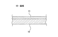
次に、基板10上にクロム膜11の膜付け(成膜)を、例えば、スパッタリング法によって行う(図4参照)。スパッタリング法による膜付けは、真空中で不活性ガスを導入しながら基板10とクロム膜11間に直流の高電圧を印加し、イオン化した不活性ガスをクロムに衝突させて飛散させ基板10にクロム膜11を成膜することにより行う。
Next, the
次いで、クロム膜11上にスピンコーターを用いてレジスト12を塗布し(図5参照)、レジスト12の溶剤を蒸発させて硬化させるために加熱し乾燥させるプリベイクを行う。
Next, a resist 12 is applied on the
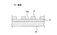
次に、レジスト12に紫外線を照射して露光を行い、続いて現像液によって現像を行ってレジスト12の一部を除去し後述する印刷用のパターンのベースとなるパターン12aを形成する(図6参照)。現像後にはリンスを行い洗浄する。パターン12aを形成した後には、水分等を蒸発させてレジスト12を焼成するための加熱乾燥工程であるポストベークを行う。
Next, exposure is performed by irradiating the resist 12 with ultraviolet rays, followed by development with a developing solution to remove a part of the resist 12 to form a
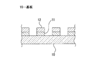
次いで、レジスト12をマスクとして用い、クロム膜11のエッチングを行う(図7参照)。エッチングとしてはドライエッチングを用いてもよく、又は、クロム膜除去液等を使用してウエットエッチングを用いてもよい。
Next, the
続いて、レジスト12をプラズマアッシングにより剥離する(図8参照)。プラズマアッシングは、酸素ガスを可視光線やマイクロ波等の非電離放射線によってプラズマ化し、レジスト12をプラズマ中の酸素ラジカルと結合させて蒸発させることにより行う。 Subsequently, the resist 12 is removed by plasma ashing (see FIG. 8). The plasma ashing is performed by converting oxygen gas into plasma by non-ionizing radiation such as visible light or microwave and combining the resist 12 with oxygen radicals in the plasma to evaporate.
次に、プラズマエッチング装置を用いて基板(石英ガラス)10をエッチング(ドライエッチング)する(図9参照)。尚、レジストをマスクとしてエッチングする方法も存在するが、基板10として石英ガラスを用いた場合には、レジストをマスクとしたときに選択比がとれないため、クロム膜11をマスクとしてエッチングを行うことが望ましい。
Next, the substrate (quartz glass) 10 is etched (dry etching) using a plasma etching apparatus (see FIG. 9). Although there is a method of etching using a resist as a mask, when quartz glass is used as the
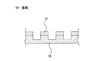
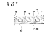
次いで、クロム膜除去液等を使用してウエットエッチングを行い、クロム膜11を除去する(図10参照)。クロム膜11を除去することにより基板10のみが残存し、パターン形成板5′が形成される。パターン形成板5′は下方側に位置する平板状のベース部5a′とベース部5a′から上方へ突出された複数の突部5b、5b、・・・とによって構成され、突部5b、5b、・・・間の複数の凹部によって所定のパターン5cが形成される。
Next, wet etching is performed using a chromium film removing solution or the like to remove the chromium film 11 (see FIG. 10). By removing the
次に、パターン形成板5′の面上にスピンコーターを用いてレジスト13を塗布し(図11参照)、レジスト13の溶剤を蒸発させて硬化させるために加熱し乾燥させるプリベイクを行う。レジスト13としては、リフトオフ加工用の有機溶剤による除去効果が大きいものを用いる。
Next, a resist 13 is applied onto the surface of the
続いて、レジスト13の表面に保護シート14を接着剤15によって貼り着ける(図12参照)。保護シート14は、後述するように、パターン形成板5′を薄型化したときのハンドリング等の際のパターン形成板5の割れを防止する機能を有する。保護シート14としては、例えば、ポリエチレンナフタレートフィルムを用い、接着剤15としては、例えば、紫外線硬化型接着剤を用いる。
Subsequently, the
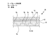
次に、パターン形成板5′の下面(レジスト13が塗布された側と反対側の面)をバブリングの機能を有するフッ酸溶液に浸漬し、エッチバックを行ってパターン形成板5′のベース部5a′を薄型化する(図13参照)。パターン形成板5′のベース部5a′がエッチバックされて薄型化されることによりパターン形成板5が形成され、パターン形成板5が、例えば、30μmの厚さにされる。尚、基板10として石英ガラス等のフッ酸のエッチングレートが遅い材料が用いられている場合には、例えば、予め、研磨装置を用いてベース部5a′を研磨し、例えば、厚さを0.7mmにし、その後にフッ酸溶液を用いてエッチバックを行って薄型化してもよい。上記のようにエッチバックを行ってパターン形成板5′を薄型化してパターン形成板5を形成することにより、パターン形成板5にレジスト13や保護シート14が被着されて成る巻回体16が構成される。
Next, the lower surface of the
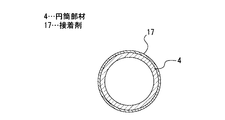
次いで、円筒部材4を準備する(図14参照)。円筒部材4は、例えば、直径が150mm、軸方向における長さが300mmとされている。準備した円筒部材4の外周面に接着剤17、例えば、紫外線硬化型接着剤を塗布する。
Next, the
続いて、巻回体16を屈曲させて円筒部材4に巻き付ける(図15参照)。このとき、円筒部材4に巻回体16を高い位置精度で巻き付けることが必要であり、例えば、巻回体16に予めレーザー光を照射して位置決め孔を形成し、円筒部材4にも予め位置決め孔を形成しておくことが望ましい。このように巻回体16と円筒部材4にそれぞれ位置決め孔を形成しておくことにより、ガラス製の位置決めピン(テーパーピン)を双方の位置決め孔に挿入し巻回体16の円筒部材4に対する正確な位置決めを行うことができる。
Subsequently, the
次に、巻回体16の外周面側から紫外線を照射して接着剤17を硬化させて巻回体16を円筒部材4に接合する(図16参照)。巻回体16の円筒部材4に対する接合の後には、位置決めピンを位置決め孔から引き抜く。
Next, the
次いで、巻回体16及び円筒部材4をアセトン又はレジスト剥離剤を充填した超音波洗浄槽に浸漬させ、リフトオフ用のレジスト13を除去する(図17参照)。レジスト13の除去時には、同時に保護シート14も剥離される。このように巻回体16のレジスト13が除去され保護シート14が剥離されることにより、印刷用のパターン5cが形成されたパターン形成板5が残存し、円筒部材4にパターン形成板5が巻き付けられて接合された版胴2が成形される。
Next, the
版胴2が成形された状態において、版胴2の強度の向上や被印刷物200に対するインク100の転写性の向上を図るために、パターン形成板5の表面にダイヤモンドライクカーボン等のコーティングを施すようにしてもよい。
In the state where the
尚、上記には、パターン形成板5をエッチバックして薄型化し版胴2を成形する例を示したが、例えば、始めから厚さ30μmの基板を準備し、エッチバックを行うことなく、上記と同様の方法により巻回体を形成し巻回体を円筒部材4に巻き付けて版胴2を成形することも可能である。
In the above, an example in which the
また、上記した版胴2の成形方法においては、接着剤17を用いて巻回体16を円筒部材4に接合しているが、接着剤17として、例えば、剥離剤の添加、紫外線の照射、加熱又は冷却によって接着力が低下するタイプを用いてもよい。
Moreover, in the molding method of the
このように接着剤17として剥離剤の添加、紫外線の照射、加熱又は冷却によって接着力が低下するタイプを用いることにより、例えば、パターン形成板5に破損や損傷が生じたときに、接着剤17に対して剥離剤の添加、紫外線の照射、加熱又は冷却を行うことによりパターン形成板5を円筒部材4から剥離し、新たなパターン形成板5を円筒部材4に接合することが可能である。新たなパターン形成板5を円筒部材4に接合することにより、パターン形成板5に破損や損傷が生じたときに、版胴2の交換を行う必要がなく、パターン形成板5のみを交換すればよく、版胴2による印刷作業におけるコストの低減を図ることができる。
Thus, by using a type in which the adhesive strength is reduced by adding a release agent, irradiating ultraviolet rays, heating or cooling as the adhesive 17, for example, when the
また、上記には、基板10にパターン5cを形成する方法として、プラズマエッチング装置を用いてエッチング(ドライエッチング)する例を示したが、基板10にパターン5cを形成する方法はプラズマエッチング装置を用いたドライエッチングに限られることはない。例えば、パターン5cを形成する方法として、ミーリングマシーン等の6軸NC(Numerical Control)工作機械を用いて基板10を削る方法やフッ酸エッチングにより基板10をエッチングする方法を用いることも可能である。
In the above, as an example of the method of forming the
[版胴の成形方法の変形例]
以下に、版胴2の成形方法の変形例について説明する(図3乃至図12、図18乃至図23参照)。
[Variation of plate cylinder molding method]
Below, the modification of the shaping | molding method of the
尚、以下に示す成形方法の変形例は、エッチバックを行う前の工程については上記した成形方法の各工程(図3乃至図12参照)と同様であるため、以下には、エッチバックを行う工程以降の工程についてのみ説明する。 In the modification of the molding method shown below, the steps before the etch back are the same as the respective steps of the molding method described above (see FIGS. 3 to 12). Only the steps after the step will be described.
版胴2の成形方法の変形例については、円筒部材4と基板10が異なる材料によって形成され、円筒部材4と基板10の各材料としては、印刷に用いられるインク100に対する付着力に関して基板10が円筒部材4より小さくなるような材料が用いられている。
As for a modification of the molding method of the
レジスト13の表面に保護シート14を接着剤15によって貼り着け(図12参照)、その後、パターン形成板5′の下面(レジスト13が塗布された側と反対側の面)をバブリングの機能を有するフッ酸溶液に浸漬し、エッチバックを行ってパターン形成板5′のベース部5a′を除去する(図18参照)。パターン形成板5′のベース部5a′がエッチバックされ除去されることによりパターン形成板5Aが形成され、パターン形成板5Aが、例えば、5μmの厚さにされる。尚、基板10として石英ガラス等のフッ酸のエッチングレートが遅い材料が用いられている場合には、例えば、予め、研磨装置を用いてベース部5a′を研磨し、その後にフッ酸溶液を用いてエッチバックを行うようにしてもよい。上記のようにエッチバックを行ってパターン形成板5′を薄型化してパターン形成板5Aを形成することにより、パターン形成板5Aにレジスト13や保護シート14が被着されて成る巻回体16Aが構成される。
A
次いで、円筒部材4を準備する(図19参照)。円筒部材4は、例えば、直径が150mm、軸方向における長さが300mmとされている。準備した円筒部材4の外周面に接着剤17、例えば、紫外線硬化型接着剤を塗布する。
Next, the
続いて、巻回体16Aを屈曲させて円筒部材4に巻き付ける(図20参照)。このとき、円筒部材4に巻回体16Aを高い位置精度で巻き付けることが必要であり、例えば、巻回体16Aに予めレーザー光を照射して位置決め孔を形成し、円筒部材4にも予め位置決め孔を形成しておくことが望ましい。このように巻回体16Aと円筒部材4にそれぞれ位置決め孔を形成しておくことにより、ガラス製の位置決めピン(テーパーピン)を双方の位置決め孔に挿入し巻回体16Aの円筒部材4に対する正確な位置決めを行うことができる。
Subsequently, the
次に、巻回体16Aの外周面側から紫外線を照射して接着剤17を硬化させて巻回体16Aを円筒部材4に接合する(図19参照)。巻回体16Aの円筒部材4に対する接合の後には、位置決めピンを位置決め孔から引き抜く。
Next, the
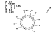
次いで、巻回体16A及び円筒部材4をアセトン又はレジスト剥離剤を充填した超音波洗浄槽に浸漬させ、リフトオフ用のレジスト13を除去する(図22参照)。レジスト13の除去時には、同時に保護シート14も剥離され、パターン5cに位置する接着剤15も除去される。このように巻回体16Aのレジスト13が除去され保護シート14が剥離されることにより、印刷用のパターン5cが形成されたパターン形成板5Aが残存し、円筒部材4にパターン形成板5Aが巻き付けられて接合された版胴2Aが成形される。
Next, the
版胴2Aが成形された状態において、版胴2Aの強度の向上や被印刷物200に対するインク100の転写性の向上を図るために、パターン形成板5Aの表面にダイヤモンドライクカーボン等のコーティングを施すようにしてもよい。
In the state where the
尚、上記した版胴2Aの成形方法においては、接着剤17を用いて巻回体16Aを円筒部材4に接合しているが、接着剤17として、例えば、剥離剤の添加、紫外線の照射、加熱又は冷却によって接着力が低下するタイプを用いてもよい。
In the molding method of the
このように接着剤17として剥離剤の添加、紫外線の照射、加熱又は冷却によって接着力が低下するタイプを用いることにより、例えば、パターン形成板5Aに破損や損傷が生じたときに、接着剤17に対して剥離剤の添加、紫外線の照射、加熱又は冷却を行うことによりパターン形成板5Aを円筒部材4から剥離し、新たなパターン形成板5Aを円筒部材4に接合することが可能である。新たなパターン形成板5Aを円筒部材4に接合することにより、パターン形成板5Aに破損や損傷が生じたときに、版胴2Aの交換を行う必要がなく、パターン形成板5Aのみを交換すればよく、版胴2Aによる印刷作業におけるコストの低減を図ることができる。
Thus, by using a type in which the adhesive strength is reduced by adding a release agent, irradiating ultraviolet rays, heating or cooling as the adhesive 17, for example, when the
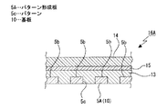
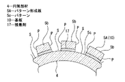
上記したように、版胴2Aはパターン形成板5Aが突部5b、5b、・・・のみによって構成されるため、図23に示すように、パターン5cの各凹部が突部5b、5b、・・・の各側面P、P、・・・と円筒部材4の外周面S、S、・・・とによって形成される。このとき、上記したように、円筒部材4と基板10の各材料として、印刷に用いられるインク100に対する付着力に関して基板10が円筒部材4より小さくなるような材料が用いられている。
As described above, the
従って、パターン5cのインク100に対する付着力に関して側面P、P、・・・の方が外周面S、S、・・・より小さくされるため、ブランケットロール3に対するインク100の良好な受理性(転写性)が確保され、被印刷物200に対する良好な印刷精度を確保することができる。
Accordingly, since the side surfaces P, P,... Are made smaller than the outer peripheral surfaces S, S,... With respect to the adhesion force of the
[まとめ]
以上に記載した通り、版胴2、2Aにあっては、パターン形成板5、5Aが屈曲され円筒部材4の外周面に巻き付けられて接合されることにより構成されている。
[Summary]
As described above, in the
従って、平板状の基板10に印刷用のパターン5cを形成すればよく、円筒状の母材の外周面に印刷用のパターンを形成する必要がないため、製造コストの高騰を来たすことなく精密な印刷用のパターン5cを形成することができる。
Therefore, it is only necessary to form the
また、基板10をエッチング(エッチバック)することにより厚みを薄くしてパターン形成板5、5Aを成形しているため、パターン形成板5、5Aの成形及び薄型化を容易に行うことができる共にパターン形成板5、5Aの厚みに関し設計の自由度の向上を図ることができる。
Further, since the
上記した最良の形態において示した各部の具体的な形状及び構造は、何れも本発明を実施する際の具体化のほんの一例を示したものにすぎず、これらによって本発明の技術的範囲が限定的に解釈されることがあってはならないものである。 The specific shapes and structures of the respective parts shown in the above-described best mode are merely examples of the implementation of the present invention, and the technical scope of the present invention is limited by these. It should not be interpreted in a general way.
1…印刷装置、2…版胴、4…円筒部材、5…パターン形成板、5c…パターン、2A…版胴、5A…パターン形成板、10…基板、17…接着剤、200…被印刷物
DESCRIPTION OF
Claims (8)
平板状の基板に微細加工によって印刷用の所定のパターンが形成されて成るパターン形成板とを備え、
前記パターン形成板が屈曲され前記円筒部材の外周面に巻き付けられて接合されることにより構成された
版胴。 A cylindrical member;
A pattern forming plate in which a predetermined pattern for printing is formed on a flat substrate by fine processing;
A plate cylinder configured by bending the pattern forming plate and winding it around the outer peripheral surface of the cylindrical member.
請求項1に記載の版胴。 The plate cylinder according to claim 1, wherein the cylindrical member and the pattern forming plate are formed of a glass material.
請求項1に記載の版胴。 The plate cylinder according to claim 1, wherein the cylindrical member and the pattern forming plate are formed of the same material.
請求項1に記載の版胴。 The plate cylinder according to claim 1, wherein the pattern forming plate is formed by reducing the thickness by etching the substrate.
請求項1に記載の版胴。 The plate cylinder according to claim 1, wherein the pattern forming plate is bonded to the outer peripheral surface of the cylindrical member with an adhesive whose adhesive strength is reduced by adding a release agent, irradiating ultraviolet rays, or heating or cooling.
前記凹部に充填されるインクに対して前記パターン形成板の付着力が前記円筒部材の付着力より小さくされた
請求項1に記載の版胴。 The predetermined pattern is formed by a plurality of recesses communicating with the outer peripheral surface of the cylindrical member;
The plate cylinder according to claim 1, wherein the adhesive force of the pattern forming plate is smaller than the adhesive force of the cylindrical member with respect to the ink filled in the concave portion.
前記版胴が回転されることにより被印刷物に対して印刷を行う
印刷装置。 A cylindrical member and a pattern forming plate formed by forming a predetermined pattern for printing on a flat substrate by fine processing, and the pattern forming plate is bent and wound around the outer peripheral surface of the cylindrical member to be joined. A plate cylinder constituted by
A printing apparatus that performs printing on an object to be printed by rotating the plate cylinder.
円筒部材の外周面に前記パターン形成板を屈曲させ巻き付けて接合して成形した
版胴の成形方法。 A pattern forming plate is formed by forming a predetermined pattern for printing on a flat substrate by fine processing,
A method of forming a plate cylinder, wherein the pattern forming plate is bent and wound around an outer peripheral surface of a cylindrical member and then joined.
Priority Applications (5)
| Application Number | Priority Date | Filing Date | Title |
|---|---|---|---|
| JP2010163993A JP2012024979A (en) | 2010-07-21 | 2010-07-21 | Plate cylinder, printing apparatus, and method of forming plate cylinder |
| TW100124606A TW201233563A (en) | 2010-07-21 | 2011-07-12 | Plate cylinder, printing apparatus, and method of forming plate cylinder |
| KR1020110069505A KR20120010137A (en) | 2010-07-21 | 2011-07-13 | Plate cylinder, printing device and method of forming plate cylinder |
| US13/181,929 US20120017788A1 (en) | 2010-07-21 | 2011-07-13 | Plate cylinder, printing apparatus, and method of forming plate cylinder |
| CN2011102016265A CN102343706A (en) | 2010-07-21 | 2011-07-14 | Plate cylinder, printing apparatus, and method of forming plate cylinder |
Applications Claiming Priority (1)
| Application Number | Priority Date | Filing Date | Title |
|---|---|---|---|
| JP2010163993A JP2012024979A (en) | 2010-07-21 | 2010-07-21 | Plate cylinder, printing apparatus, and method of forming plate cylinder |
Publications (1)
| Publication Number | Publication Date |
|---|---|
| JP2012024979A true JP2012024979A (en) | 2012-02-09 |
Family
ID=45492491
Family Applications (1)
| Application Number | Title | Priority Date | Filing Date |
|---|---|---|---|
| JP2010163993A Pending JP2012024979A (en) | 2010-07-21 | 2010-07-21 | Plate cylinder, printing apparatus, and method of forming plate cylinder |
Country Status (5)
| Country | Link |
|---|---|
| US (1) | US20120017788A1 (en) |
| JP (1) | JP2012024979A (en) |
| KR (1) | KR20120010137A (en) |
| CN (1) | CN102343706A (en) |
| TW (1) | TW201233563A (en) |
Cited By (1)
| Publication number | Priority date | Publication date | Assignee | Title |
|---|---|---|---|---|
| WO2013171895A1 (en) * | 2012-05-18 | 2013-11-21 | Sakamoto Jun | Printer, printing device, and printing method |
Families Citing this family (6)
| Publication number | Priority date | Publication date | Assignee | Title |
|---|---|---|---|---|
| KR102080731B1 (en) * | 2013-05-28 | 2020-02-25 | 삼성디스플레이 주식회사 | Method for preparing organic electroluminescence device |
| CN105068324B (en) * | 2015-08-28 | 2019-02-22 | 武汉华星光电技术有限公司 | The manufacturing method and glue frame of liquid crystal display panel solidify the manufacturing method of mask plate |
| CN105700249B (en) * | 2016-04-29 | 2019-03-15 | 京东方科技集团股份有限公司 | Alignment plate production device and alignment plate production method |
| JP6969156B2 (en) * | 2016-05-30 | 2021-11-24 | Agc株式会社 | Board with printed layer, its manufacturing method, and display device |
| CN108121118A (en) * | 2017-12-28 | 2018-06-05 | 武汉华星光电技术有限公司 | Liquid crystal coating equipment |
| TWI742901B (en) * | 2020-10-30 | 2021-10-11 | 光群雷射科技股份有限公司 | Manufacturing method of transfer roller and manufacturing method of transfer film |
-
2010
- 2010-07-21 JP JP2010163993A patent/JP2012024979A/en active Pending
-
2011
- 2011-07-12 TW TW100124606A patent/TW201233563A/en unknown
- 2011-07-13 KR KR1020110069505A patent/KR20120010137A/en not_active Withdrawn
- 2011-07-13 US US13/181,929 patent/US20120017788A1/en not_active Abandoned
- 2011-07-14 CN CN2011102016265A patent/CN102343706A/en active Pending
Cited By (2)
| Publication number | Priority date | Publication date | Assignee | Title |
|---|---|---|---|---|
| WO2013171895A1 (en) * | 2012-05-18 | 2013-11-21 | Sakamoto Jun | Printer, printing device, and printing method |
| CN104302480A (en) * | 2012-05-18 | 2015-01-21 | 阪本顺 | Printer, printing device, and printing method |
Also Published As
| Publication number | Publication date |
|---|---|
| CN102343706A (en) | 2012-02-08 |
| TW201233563A (en) | 2012-08-16 |
| KR20120010137A (en) | 2012-02-02 |
| US20120017788A1 (en) | 2012-01-26 |
Similar Documents
| Publication | Publication Date | Title |
|---|---|---|
| JP2012024979A (en) | Plate cylinder, printing apparatus, and method of forming plate cylinder | |
| CN104838485B (en) | Detachable substrate on support plate | |
| KR101444604B1 (en) | Cliche and printing apparatus comprising the same | |
| JP6357777B2 (en) | Method for manufacturing laminated mask | |
| JP6256000B2 (en) | Method for manufacturing vapor deposition mask device | |
| JP2009034913A (en) | Flexographic printing plate, method for producing the same, thin film, and method for producing liquid crystal display element | |
| JP5899585B2 (en) | Mask manufacturing method | |
| US20070062639A1 (en) | Method for manufacturing a flexible display | |
| CN103415381B (en) | The manufacture method of mould, mould and the manufacture method of nano impression film | |
| KR20170126862A (en) | Manufacturing method for relief pattern forming body and imprint apparatus | |
| JP2011005768A (en) | Master plate used for manufacturing of stamp for micro contact print, method of manufacturing the same, stamp for micro contact print, method of manufacturing of the same and pattern forming method using stamp for micro contact print | |
| KR20090019200A (en) | Imprint master, its manufacturing method and imprint method using the master | |
| CN104391614B (en) | Intaglio plate micro-shifting prints the method for making touch panel sensor | |
| JP4588041B2 (en) | Printing plate manufacturing method using resin mold | |
| KR20110003084A (en) | Offset printing intaglio and manufacturing method thereof | |
| CN112689797A (en) | Method for manufacturing a stamp for imprint lithography, imprint roller, and roll-to-roll substrate processing apparatus | |
| CN104220647B (en) | Continuous plating pattern formation roller and its manufacture method | |
| KR20100028330A (en) | Fablicating method of cylinder having fine patterns | |
| JP6358488B2 (en) | Method for producing offset printing cliché and offset printing cliché | |
| JP6497596B2 (en) | Intermediate of vapor deposition mask device | |
| KR20160145952A (en) | Master mold and a method of manufacturing the same | |
| JP7219999B1 (en) | FLEXOGRAPHIC PLATE, ITS MANUFACTURING METHOD AND HEAT CUT DEVICE | |
| JP2007093839A (en) | Versions and how to play them | |
| JP2024103953A (en) | Flexographic plate, its manufacturing method and heat cutting device | |
| JP7493704B2 (en) | Printing device and printing method |