JP2012024976A - Lug member insertion device and method of setting vulcanized lug member - Google Patents
Lug member insertion device and method of setting vulcanized lug member Download PDFInfo
- Publication number
- JP2012024976A JP2012024976A JP2010163932A JP2010163932A JP2012024976A JP 2012024976 A JP2012024976 A JP 2012024976A JP 2010163932 A JP2010163932 A JP 2010163932A JP 2010163932 A JP2010163932 A JP 2010163932A JP 2012024976 A JP2012024976 A JP 2012024976A
- Authority
- JP
- Japan
- Prior art keywords
- lug
- lug member
- insertion device
- center post
- vulcanized
- Prior art date
- Legal status (The legal status is an assumption and is not a legal conclusion. Google has not performed a legal analysis and makes no representation as to the accuracy of the status listed.)
- Granted
Links
Images
Landscapes
- Moulds For Moulding Plastics Or The Like (AREA)
- Tyre Moulding (AREA)
Abstract
Description
本発明は、ラグタイヤを製造するに当たり、あらかじめ加硫を施した加硫済みラグ部材を用いる場合に使用される、加硫モールドに対するラグ部材の挿入装置、及びこのラグ部材挿入装置を用いた加硫済みラグ部材のセット方法に関するものである。 The present invention relates to an apparatus for inserting a lug member into a vulcanization mold, and a vulcanization using the lug member insertion apparatus, which are used when a vulcanized lug member that has been vulcanized in advance is used in manufacturing a lag tire. The present invention relates to a method for setting a finished lug member.
ラグタイヤを製造するに当たっては、各個のラグに対応する溝を設けた加硫モールドに生タイヤを装填し、型締め成形によって生タイヤのゴムを加硫モールドの溝内に流入させて、タイヤのトレッドにラグを突出形成することが広く一般に行われている(例えば特許文献1参照)。 In manufacturing lag tires, raw tires are loaded into a vulcanization mold provided with grooves corresponding to each lug, and rubber of the raw tire is caused to flow into the grooves of the vulcanization mold by mold clamping, so that the tire tread In general, the lug is formed in a protruding manner (see, for example, Patent Document 1).
上記のようにして製造されるラグタイヤでは、生タイヤのゴムが加硫モールドの溝内に流入するに伴って、タイヤトレッドのラグの周辺部では、各ラグが大きな体積を占めるが故に、大きな変形が生じ、タイヤの表面に不要の凹凸が発生することがあり、また、ラグ周辺部のタイヤ内部では、カーカスプライやベルトによれが発生して、タイヤの性能に影響を与えることもあった。 In the lag tire manufactured as described above, as the rubber of the raw tire flows into the groove of the vulcanization mold, the lag of the tire tread has a large volume at the periphery of the lug of the tire tread. As a result, unnecessary irregularities may occur on the surface of the tire, and carcass plies and belts may occur inside the tire around the lug, affecting the performance of the tire.
このような問題に対応するものとして、あらかじめ加硫を施した加硫済みラグ部材を準備しておき、このラグ部材を加硫モールドのラグ形成溝内に挿入した後、生タイヤを加硫モールドに装入して加硫成形を行って、ラグ部材と生タイヤとを相互に結合させる方法が検討されている。これによれば、加硫モールドの溝内へのゴムの流れ込みは抑えられることになるが、各ラグ部材を所定の溝内に位置決め配置するに当たっては、加硫モールドの内側に手を入れる作業が必要となるという安全上の問題があり、また、ラグ部材を1個ずつ溝内に挿入することに時間がかかってしまうため作業性が悪く、さらに、ラグ部材の、加硫モールドへの手作業による挿入作業は、生タイヤと接合するラグ部材のベースに手が触れて汚れてしまい、接着力が低下して生タイヤとの結合が阻害される懸念もあったので、これらの問題を有効に解決することが望まれていた。 In order to cope with such a problem, a vulcanized lug member that has been vulcanized in advance is prepared, and after this lug member is inserted into the lug forming groove of the vulcanization mold, the raw tire is vulcanized. A method is being studied in which the lug member and the green tire are bonded to each other by charging into a vulcanized product and performing vulcanization molding. According to this, the flow of rubber into the groove of the vulcanization mold can be suppressed, but when positioning and arranging each lug member within the predetermined groove, an operation of putting a hand inside the vulcanization mold is required. There is a safety problem that it is necessary, and it takes time to insert lug members into the groove one by one, so that workability is poor, and furthermore, manual work of the lug member to the vulcanization mold The insertion work by, because there is a concern that the hand touches the base of the lug member to be joined with the raw tire, and there is a concern that the adhesion force will be reduced and the connection with the raw tire will be hindered. It was hoped that this would be solved.
本発明の課題は、加硫モールド内に、作業者の手作業によらずに、加硫済みの複数のラグ部材を、所要の位置に所期した通りに自動的にセットすることができ、それゆえ、ラグ部材のベースに手が触れるおそれがなく、また複数のラグ部材を一度に、同時に位置決め配置することを可能とする、簡単な構造のラグ部材挿入装置、及びこのラグ部材装置を用いた加硫済みラグ部材のセット方法を提供することにある。 The object of the present invention is to automatically set a plurality of vulcanized lug members in a vulcanization mold as expected at a required position without depending on the manual work of an operator. Therefore, there is no possibility that the hand touches the base of the lug member, and it is possible to position and arrange a plurality of lug members at the same time, and to use this lug member device. Another object of the present invention is to provide a method for setting a vulcanized lug member.
本発明は、タイヤの、上下の加硫モールド間に配置され、両加硫モールドの閉作動に伴って、ラグタイヤの加硫済みラグ部材を、加硫モールドのラグ形成溝内に挿入配置するラグ部材挿入装置であって、
上下の伸長方向に付勢され、前記加硫モールドの開閉作動に伴って伸縮変形されるセンターポストと、該センターポストの上下の端部に一端をヒンジ連結され、他端部に掛合爪を有する、上下に対をなす揺動アームと、該センターポストの中間部から突設されて該加硫モールドの半径方向外方に向けて水平姿勢で付勢され、該揺動アーム対との協働下で、先端に前記加硫済みラグ部材を付勢力に抗して掛合保持する押し込みロッドとを具えてなる、ラグ部材挿入装置である。
The present invention is a lug which is arranged between upper and lower vulcanization molds of a tire and which inserts and arranges a vulcanized lug member of a rug tire into a lug forming groove of the vulcanization mold in accordance with the closing operation of both vulcanization molds. A member insertion device comprising:
A center post that is urged in an up-and-down extension direction and expands and contracts in accordance with the opening and closing operation of the vulcanization mold, one end is hinge-connected to the upper and lower ends of the center post, and a hooking claw is provided at the other end The upper and lower swing arms and the center post projecting from an intermediate portion of the center post and urged in a horizontal posture outwardly in the radial direction of the vulcanization mold. Below, it is a lag member insertion apparatus provided with the pushing rod which latches and hold | maintains the said vulcanized lag member against an urging | biasing force at the front-end | tip.
またこの装置では、センターポストの上部及び下部の少なくとも一方に配設されて、センターポストの中心軸線の周りに間隔をおいて複数配設したそれぞれの揺動アーム間に嵌まり込んで、揺動アームの相互間の角度間隔を特定する位置合わせ部材を設けることが好ましい。 In this device, the center post is disposed on at least one of the upper part and the lower part of the center post, and is fitted between the plurality of swing arms arranged at intervals around the center axis of the center post. It is preferable to provide an alignment member that specifies the angular interval between the arms.
ところで、前記押し込みロッドは、前記センターポストの中心軸線の周りに、上下方向に間隔をおく千鳥状に設けることが好ましい。 By the way, it is preferable that the push rods are provided in a zigzag shape with a space in the vertical direction around the center axis of the center post.
この発明の、加硫済みラグ部材のセット方法は、先に述べた何れかのラグ部材挿入装置を用いて、加硫済みラグ部材を加硫モールドの所定位置にセットするに当たり、
複数の加硫済みラグ部材を該ラグ部材挿入装置に装着し、次いで、該ラグ部材挿入装置を上下の加硫モールド間に配置し、その後、該加硫モールドの閉作動に伴って該ラグ部材挿入装置が保持する複数の加硫済みラグ部材を該加硫モールドのラグ形成溝内に挿入し、さらに、該ラグ部材挿入装置を、該加硫モールドの開放姿勢下で加硫モールドから取り出すにある。
The method of setting the vulcanized lug member of the present invention uses any of the lug member insertion devices described above to set the vulcanized lug member at a predetermined position of the vulcanization mold.
A plurality of vulcanized lug members are mounted on the lug member insertion device, and then the lug member insertion device is disposed between the upper and lower vulcanization molds, and then the lug member is operated along with the closing operation of the vulcanization mold. Inserting a plurality of vulcanized lug members held by the insertion device into the lug forming groove of the vulcanization mold, and further removing the lag member insertion device from the vulcanization mold with the vulcanization mold open. is there.
この発明のラグ部材挿入装置では、特に、伸長方向に付勢される押し込みロッドの先端に揺動アーム対との協働下で、加硫済みラグ部材を、そのロッドの付勢力に抗して掛合保持した状態でラグ部材挿入装置を加硫モールド内に配置し、この加硫モールドを閉作動させることで、複数のラグ部材を、加硫モールドの所定の位置へ自動的に同時にかつ所期した通りに正確に挿入することができる。従ってこの装置によれば、個々のラグ部材を、作業者の手作業によらずにセットできるので、ラグ部材の取り付け作業性を改善させることができる。 In the lug member insertion device of the present invention, in particular, the vulcanized lug member is resisted against the urging force of the rod in cooperation with the swing arm pair at the tip of the push rod urged in the extending direction. By placing the lug member insertion device in the vulcanization mold while being hooked and holding, and closing the vulcanization mold, a plurality of lug members are automatically and simultaneously brought into a predetermined position of the vulcanization mold. You can insert exactly as you did. Therefore, according to this device, the individual lug members can be set without depending on the manual operation of the operator, so that the workability of attaching the lug members can be improved.
またこの装置で、各揺動アームの間に嵌まり込んで、揺動アームの相互間の角度間隔を特定する位置合わせ部材を設けた場合は、加硫モールドの作動に基づいて装置が作用している間でも、揺動アームのがたつき等に起因する位置精度の低下を抑制することができる。従ってこれによれば、簡易な構造の下で、揺動アームの、経時的な精度低下をも含む各種の精度低下を有効に吸収することができる。 In addition, when this apparatus is provided with an alignment member that fits between the swing arms and specifies the angular interval between the swing arms, the apparatus operates based on the operation of the vulcanization mold. Even during this time, it is possible to suppress a decrease in positional accuracy due to the shaking of the swing arm. Therefore, according to this, under the simple structure, it is possible to effectively absorb various accuracy reductions including the temporal accuracy deterioration of the swing arm.
ここで、押し込みロッドをセンターポストの中心軸線の周りに、上下方向に間隔をおく千鳥状に設けた時は、ラグを、トレッド幅方向に左右交互の千鳥状配置とするラグタイヤにあっても、ラグ部材を一度に挿入することができる。従ってこの装置によれば、押し込みロッド高さが異なる複数の装置によらず、1つの装置で、全ての加硫済み部材を一度に挿入することができる。 Here, when the push rods are provided in a zigzag shape with a space in the vertical direction around the center axis of the center post, even if the lugs are in a staggered arrangement of left and right alternating in the tread width direction, The lug members can be inserted at once. Therefore, according to this device, it is possible to insert all the vulcanized members at one time with one device regardless of a plurality of devices having different push rod heights.
さらにこの装置を用いて加硫済みラグ部材を加硫モールドの所定位置にセットするに当たっては、複数の加硫済みラグ部材を装着したラグ部材挿入装置を、加硫モールド間に配置して加硫モールドを閉作動させるだけで、それらの各ラグ部材を所定の位置へ自動的に挿入することができる。従ってこの装置によれば、加硫モールドの内側に作業者が手を入れる必要がなくなり、ラグ部材の挿入作業を安全に行うことができるとともに、複数のラグ部材を、一度に、所期した通りに正確に位置決め配置することができる。 Furthermore, when setting the vulcanized lug member at a predetermined position of the vulcanization mold using this apparatus, a lag member insertion device equipped with a plurality of vulcanized lug members is arranged between the vulcanization molds and vulcanized. Each lug member can be automatically inserted into a predetermined position simply by closing the mold. Therefore, according to this apparatus, it is not necessary for an operator to put a hand inside the vulcanization mold, the lug member can be inserted safely, and a plurality of lug members can be attached at a time as expected. Can be positioned accurately.
以下、図面を参照して、本発明をより具体的に説明する。 Hereinafter, the present invention will be described more specifically with reference to the drawings.
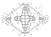
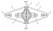
図1に示すところにおいて、1は、ラグ部材挿入装置の全体である。ラグ部材挿入装置1は、その中央に起立するセンターポスト2と、センターポスト2の上下の端部に一端をヒンジ連結され、他端部に掛合爪を有する、上下に対をなす揺動アーム3の複数対と、センターポスト2の中間部から水平方向に突出させて設けた押し込みロッド4とを具えている。対をなす揺動アーム3の掛合爪と押し込みロッド4との間には、後述するようにして、加硫済みのラグ部材5を保持することができる。
In FIG. 1, 1 is the whole lug member insertion apparatus. The lug
センターポスト2は、上下方向に伸縮するテレスコピックとなっており、さらに伸長方向に付勢力を有している。具体的な構造は、例えば図1に示すように、上部先端に先端ロッド2aを設け、この先端ロッド2aから下方に向けて筒体2b乃至2eを順に配置する。先端ロッド2aの下端には、先端ロッド2aの中間部よりも大径となる抜け止めストッパー2a1が設けられている。抜け止めストッパー2a1の外側は、筒体2bで取り囲まれており、筒体2bの下端にはこの筒体2bよりも大径となる底壁2b1が設けられ、筒体2bの上端には、中央に先端ロッド2aの中間部が貫通する孔を形成した天壁2b2が設けられている。また抜け止めストッパー2a1と底壁2b1との間には、ばねS1が設けられており、先端ロッド2aは、上下に摺動可能であるとともに上方へ向けて常時付勢されている。筒体2c、2d、2eも、筒体2bと同様の構成で配置されており、さらに筒体2eの下方には、上記2a乃至2eと対称となるように、2a´乃至2e´が設けられている。
The
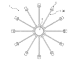
揺動アーム3は、上下に対をなして配置されており、上部に位置する上側揺動アーム3aの一端である支持部3a1を、先端ロッド2aの上端フランジにヒンジ連結し、下部に位置する下側揺動アーム3a´の一端である支持部3a´1を、先端ロッド2a´の下端フランジにヒンジ連結している。また例えば、上側揺動アーム3a及び下側揺動アーム3a´は、互いに近づく向き(図1に示す矢印の向き)に付勢力を受けている。付勢力の付与は、例えば支持部3a1及び3a´1の近傍に、ねじりばねや、ひげばね、板ばね等を設けることで実現される。また上側揺動アーム3a及び下側揺動アーム3a´の他端には、それぞれ鉤状の掛合爪3a2及び3a´2が設けられており、ラグ部材挿入装置1の初期姿勢(センターポスト2が伸びた姿勢)において、それぞれ下方及び上方に延びている。図2に示すように揺動アーム3は、センターポスト2を中心として、放射状に複数(図示の例では12本)設けられている。
The
押し込みロッド4は、センターポスト2の中間部より、半径方向外方に向けて水平姿勢でもって突設された、水平方向に伸縮するテレスコピックとなっており、さらに伸長方向に付勢力を有している。具体的な構造は、センターポスト2と同様の構成とすることができ、例えば図1に示すように、押し込みロッド4の半径方向最も外方の先端ロッド4aから筒体4eに至るまで、相互間にばねS2を配置し、互いを摺動可能に、かつ半径方向外方に向けて常時付勢させている。ここで、押し込みロッド4のばねS2全体の付勢力は、センターポスト2のばねS1全体の付勢力に対して小さくなっている。このため、図1に示す初期姿勢においては、センターポスト2は伸びた状態となっている一方、押し込みロッド4は、縮んだ状態となっている。また、図2に示すように押し込みロッド4は、揺動アーム3と同様に、センターポスト2を中心として、放射状に複数(図示の例では12本)設けられている。
The
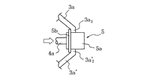
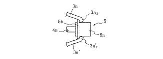
ラグ部材5は、ラグタイヤのラグに相当するラグ本体5aと、ラグ部材5と生タイヤとの接合部となるベース5bからなり、ベース5bがラグ本体5aからフランジ状に突出している。図1に示す初期姿勢の状態で、ラグ部材5は、図3に詳細に示すように、ベース5bの裏面(ラグ本体5aが突出する側とは反対の面)が、先端ロッド4aの先端フランジ部と当接して、半径方向外方に向かう付勢力が付与されている一方、ベース5bの表面に、揺動アーム3の掛合爪3a2及び3a´2が、先端ロッド4aの伸長方向と略直交する向きに掛合してこの付勢力に抗しており、先端ロッド4aと掛合爪3a2及び3a´2の間で保持されている。
The
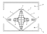
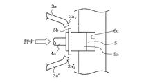
ラグ部材挿入装置1を用いて加硫済みラグ部材のセットを行うに当たっては、まずラグ部材挿入装置1に所定の数のラグ部材5を保持しておき、このラグ部材挿入装置1を、例えばローダー等の作用によって、図4に示すように、加硫モールド6の上型6aと下型6bの間に、位置決め配置する。その後加硫モールド6を閉じていくと、ラグ部材挿入装置1のセンターポスト2が縮んでいき、ラグ部材5は、押し込みロッド4の内蔵ばねの付勢力に基づいて、加硫モールド6の半径方向外方へ移動していく。さらに加硫モールド6を閉じると、図5に示すように、センターポスト2は収縮変形し、これに連動して、揺動アーム3は水平方向に近づく向きに揺動し、揺動アーム3の各掛合爪3a2、3a´2の鉤状先端は、半径方向外方に向けて変位する。このときラグ部材5は、押し込みロッド4に押されて、掛合爪3a2、3a´2とともに半径方向外方に向けて変位し、図6に示すように、掛合爪3a2、3a´2それ自体が、先端ロッド4aの伸長方向と平行に近づく向きに傾いていく。このため掛合爪3a2、3a´2が、さらに平行に近づいていくと、押し込みロッド4の付勢力を阻止することができず、ラグ部材5は、図7に示すように揺動アーム3から外れ、押し込みロッド4によってそれぞれのラグ形成溝6c内に押し込まれる。次いで加硫モールド6を開き、ラグ部材挿入装置1を加硫モールド6からローダー等で取り出し、ラグ部材5のセットが完了する。しかる後は、加硫モールド6内に生タイヤを装入し、ラグタイヤ全体の加硫を行って、ラグ部材5を生タイヤに一体連結させてなる製品タイヤとする。これにより、加硫モールド6に手を入れる必要がなくなり、それ故ラグ形成溝6cへの取り付け時に、ラグ部材5のベース5bに手が触れるおそれがなくなる。さらに複数のラグ部材5を、ラグ形成溝6cに一度に配置することが可能となる。
In setting the vulcanized lug member using the lug
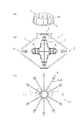
ラグ部材挿入装置1を上述したように機能させるに当たっては、図8(a)に示す、位置合わせ部材7を設けてなることが好ましい。図示のように位置合わせ部材7は、基部7aが複数の突起7bを具えており、この位置合わせ部材7は、所定の位置、方向等の特定下で、センターポスト2の上部及び下部の少なくとも一方に配置される。このとき突起7bは、図8(b)、(c)に示すように、隣り合う揺動アーム3の相互間に嵌まり込んで、角度間隔が特定される。このため、装置に経時的な誤差等が発生しても揺動アーム3のがたつきが抑制され、確実に周方向の位置決めを行うことができる。位置合わせ部材7を、上部及び下部の両方に配置する場合は、より確実に位置決めを行うことができる。
In order to make the lug
ところで、現実のラグタイヤのラグの形成態様を考慮したときは、押し込みロッド4を、センターポスト2の軸周りに、上下に間隔をおく千鳥状に設けることが好ましい。ラグを、トレッド幅方向に左右交互の千鳥状配置とするラグタイヤに対しても、押し込みロッド高さの異なる複数のラグ部材挿入装置1を用いることなく、1つのラグ部材挿入装置1によってラグ部材5を挿入することができる。
By the way, when considering the form of the lug of an actual lug tire, it is preferable to provide the
なお、揺動アーム3は、センターポスト2とのヒンジ連結に代えてセンターポスト2と固着させて、片持ちばりとして機能するようにしてもよい。
The
また、図示の例でセンターポスト2及び押し込みロッド4は、複数のばねを用いた場合を示したが、例えば筒体2bの底壁2b1をはじめとする各中間の筒体の底壁に、ばねを通す穴を設け、先端から根元まで延びる1本のばねで付勢力を与えるようにしてもよい。
Further, in the illustrated example, the
1 ラグ部材挿入装置
2 センターポスト
3 揺動アーム
4 押し込みロッド
5 ラグ部材
5a ラグ本体
5b ベース
6 加硫モールド
6a 上型
6b 下型
6c ラグ形成溝
7 位置合わせ部材
7a 基部
7b 突起
S1 ばね
S2 ばね
1 lug
Claims (4)
上下の伸長方向に付勢され、前記加硫モールドの開閉作動に伴って伸縮変形されるセンターポストと、該センターポストの上下の端部に一端をヒンジ連結され、他端部に掛合爪を有する、上下に対をなす揺動アームと、該センターポストの中間部から突設されて該加硫モールドの半径方向外方に向けて水平姿勢で付勢され、該揺動アーム対との協働下で、先端に前記加硫済みラグ部材を付勢力に抗して掛合保持する押し込みロッドとを具えてなる、ラグ部材挿入装置。 A lug member insertion device that is disposed between upper and lower vulcanization molds of a tire and inserts and arranges a vulcanized lug member of a lag tire into a lug forming groove of the vulcanization mold in accordance with the closing operation of both vulcanization molds. There,
A center post that is urged in an up-and-down extension direction and expands and contracts in accordance with the opening and closing operation of the vulcanization mold, one end is hinge-connected to the upper and lower ends of the center post, and a hooking claw is provided at the other end The upper and lower swing arms and the center post projecting from an intermediate portion of the center post and urged in a horizontal posture outwardly in the radial direction of the vulcanization mold. A lug member insertion device comprising a push rod that holds the vulcanized lug member at the tip thereof against an urging force.
複数の加硫済みラグ部材を該ラグ部材挿入装置に装着し、次いで、該ラグ部材挿入装置を上下の加硫モールド間に配置し、その後、該加硫モールドの閉作動に伴って該ラグ部材挿入装置が保持する複数の加硫済みラグ部材を該加硫モールドのラグ形成溝内に挿入し、さらに、該ラグ部材挿入装置を、該加硫モールドの開放姿勢下で加硫モールドから取り出す、加硫済みラグ部材のセット方法。 A method for setting a vulcanized lug member using the lug member insertion device according to any one of claims 1 to 3,
A plurality of vulcanized lug members are mounted on the lug member insertion device, and then the lug member insertion device is disposed between the upper and lower vulcanization molds, and then the lug member is operated along with the closing operation of the vulcanization mold. Inserting a plurality of vulcanized lug members held by the insertion device into the lag forming groove of the vulcanization mold, and further removing the lag member insertion device from the vulcanization mold under the open posture of the vulcanization mold; Setting method of vulcanized lug member.
Priority Applications (1)
| Application Number | Priority Date | Filing Date | Title |
|---|---|---|---|
| JP2010163932A JP5503443B2 (en) | 2010-07-21 | 2010-07-21 | Lug member insertion device and method for setting vulcanized lug member |
Applications Claiming Priority (1)
| Application Number | Priority Date | Filing Date | Title |
|---|---|---|---|
| JP2010163932A JP5503443B2 (en) | 2010-07-21 | 2010-07-21 | Lug member insertion device and method for setting vulcanized lug member |
Publications (2)
| Publication Number | Publication Date |
|---|---|
| JP2012024976A true JP2012024976A (en) | 2012-02-09 |
| JP5503443B2 JP5503443B2 (en) | 2014-05-28 |
Family
ID=45778521
Family Applications (1)
| Application Number | Title | Priority Date | Filing Date |
|---|---|---|---|
| JP2010163932A Expired - Fee Related JP5503443B2 (en) | 2010-07-21 | 2010-07-21 | Lug member insertion device and method for setting vulcanized lug member |
Country Status (1)
| Country | Link |
|---|---|
| JP (1) | JP5503443B2 (en) |
Cited By (1)
| Publication number | Priority date | Publication date | Assignee | Title |
|---|---|---|---|---|
| JP2013000971A (en) * | 2011-06-16 | 2013-01-07 | Bridgestone Corp | Tire vulcanizing apparatus |
Citations (3)
| Publication number | Priority date | Publication date | Assignee | Title |
|---|---|---|---|---|
| JPS60184831A (en) * | 1984-03-03 | 1985-09-20 | Ohtsu Tire & Rubber Co Ltd | Manufacture of pneumatic tire with lug |
| JPH08207056A (en) * | 1995-02-07 | 1996-08-13 | Bridgestone Corp | Plasma forming apparatus for washing vulcanizing mold and electrode thereof |
| JP2006088664A (en) * | 2004-09-27 | 2006-04-06 | Bridgestone Corp | Manufacturing method of rubber crawler |
-
2010
- 2010-07-21 JP JP2010163932A patent/JP5503443B2/en not_active Expired - Fee Related
Patent Citations (3)
| Publication number | Priority date | Publication date | Assignee | Title |
|---|---|---|---|---|
| JPS60184831A (en) * | 1984-03-03 | 1985-09-20 | Ohtsu Tire & Rubber Co Ltd | Manufacture of pneumatic tire with lug |
| JPH08207056A (en) * | 1995-02-07 | 1996-08-13 | Bridgestone Corp | Plasma forming apparatus for washing vulcanizing mold and electrode thereof |
| JP2006088664A (en) * | 2004-09-27 | 2006-04-06 | Bridgestone Corp | Manufacturing method of rubber crawler |
Cited By (1)
| Publication number | Priority date | Publication date | Assignee | Title |
|---|---|---|---|---|
| JP2013000971A (en) * | 2011-06-16 | 2013-01-07 | Bridgestone Corp | Tire vulcanizing apparatus |
Also Published As
| Publication number | Publication date |
|---|---|
| JP5503443B2 (en) | 2014-05-28 |
Similar Documents
| Publication | Publication Date | Title |
|---|---|---|
| US9046445B2 (en) | Rim assembly, tire testing machine, and rim assembly replacement method | |
| JP6372035B2 (en) | Tire mounting mechanism | |
| BRPI0917296B1 (en) | METHOD AND DEVICE FOR TRANSFERING AND PLACING TIPS AND SPACER TO BE USED WITH THE SAME | |
| JPWO2016167018A1 (en) | Fuel tank | |
| JP5503443B2 (en) | Lug member insertion device and method for setting vulcanized lug member | |
| CN103373186A (en) | A tyre removal tool for a tyre removing machine and a tyre removing machine | |
| US20120061028A1 (en) | Working tool orienting device in tire demounting machine | |
| PT2155464E (en) | Demolding device for demolding a tool from a mold | |
| US20150144273A1 (en) | Device for demounting a tired wheel as well as a machine including such device | |
| CN102712151B (en) | Pressurized vulcanizer | |
| KR101873874B1 (en) | Bobbin for wire winding | |
| CN206034130U (en) | Clothes hanger that dries in air goes up and down to connect fixed establishment | |
| BR202017022646U2 (en) | SUPPORT PLATE FOR A SPRING IN A VEHICLE SUSPENSION | |
| CN203553488U (en) | Positioning device | |
| CN109129272B (en) | A clamp structure for assembling a handle lock | |
| JP6281643B2 (en) | Method and apparatus for manufacturing tire vulcanization bladder assembly | |
| CN206344725U (en) | A kind of headrest assemblies and electric vehicle | |
| JP4416326B2 (en) | Suspension device for tire carcass with vertical axis | |
| CN205499077U (en) | Fixed knot of bonnet vaulting pole constructs | |
| KR101958212B1 (en) | Apparatus and method for manufacturing normal member | |
| JP6372289B2 (en) | Method and apparatus for conveying bead member | |
| CN217941574U (en) | Automobile silencer cone mould | |
| CN216471707U (en) | Developer lifting and transferring head | |
| CN111386182A (en) | Apparatus and method for overmolding glass sheets and inserts, and inserts used by the apparatus and method | |
| CN217255821U (en) | Car body top cover split charging positioning assembly |
Legal Events
| Date | Code | Title | Description |
|---|---|---|---|
| A621 | Written request for application examination |
Free format text: JAPANESE INTERMEDIATE CODE: A621 Effective date: 20130618 |
|
| A977 | Report on retrieval |
Free format text: JAPANESE INTERMEDIATE CODE: A971007 Effective date: 20140205 |
|
| TRDD | Decision of grant or rejection written | ||
| A01 | Written decision to grant a patent or to grant a registration (utility model) |
Free format text: JAPANESE INTERMEDIATE CODE: A01 Effective date: 20140212 |
|
| A61 | First payment of annual fees (during grant procedure) |
Free format text: JAPANESE INTERMEDIATE CODE: A61 Effective date: 20140314 |
|
| R150 | Certificate of patent or registration of utility model |
Ref document number: 5503443 Country of ref document: JP Free format text: JAPANESE INTERMEDIATE CODE: R150 |
|
| R250 | Receipt of annual fees |
Free format text: JAPANESE INTERMEDIATE CODE: R250 |
|
| R250 | Receipt of annual fees |
Free format text: JAPANESE INTERMEDIATE CODE: R250 |
|
| R250 | Receipt of annual fees |
Free format text: JAPANESE INTERMEDIATE CODE: R250 |
|
| R250 | Receipt of annual fees |
Free format text: JAPANESE INTERMEDIATE CODE: R250 |
|
| LAPS | Cancellation because of no payment of annual fees |