JP2012024941A - Method for thickness control of stretched blow molding film - Google Patents
Method for thickness control of stretched blow molding film Download PDFInfo
- Publication number
- JP2012024941A JP2012024941A JP2010162900A JP2010162900A JP2012024941A JP 2012024941 A JP2012024941 A JP 2012024941A JP 2010162900 A JP2010162900 A JP 2010162900A JP 2010162900 A JP2010162900 A JP 2010162900A JP 2012024941 A JP2012024941 A JP 2012024941A
- Authority
- JP
- Japan
- Prior art keywords
- film
- thickness
- section
- film thickness
- controlling
- Prior art date
- Legal status (The legal status is an assumption and is not a legal conclusion. Google has not performed a legal analysis and makes no representation as to the accuracy of the status listed.)
- Granted
Links
Images
Landscapes
- Shaping By String And By Release Of Stress In Plastics And The Like (AREA)
Abstract
【課題】フィルムブロー設備において製造されたフィルムを平坦化後にストレッチ設備において、最終フィルムがフィルム中央からフィルム縁辺部に向かって可能な限り小さな厚さ増幅部を有する厚さ断面を有するように、機械方向において一軸に延伸することを可能にする解決手段を提供することである。
【解決手段】フィルムブロー設備(1)において製造されたチューブラフィルム(6)のフィルム厚さ断面を、ストレッチングにより、フィルム幅全体にわたって平均的なフィルム厚さから可能な限り小さな偏差を有する厚さ横断面を持ったフィルムが製造されるように制御するようにした。
【選択図】なしIn a stretch facility after flattening a film produced in a film blowing facility, a machine is provided so that the final film has a thickness cross section having a thickness amplifying portion as small as possible from the film center toward the film edge. It is to provide a solution that makes it possible to stretch uniaxially in the direction.
A thickness having a deviation as small as possible from an average film thickness over the entire film width by stretching a film thickness section of a tubular film (6) produced in a film blowing facility (1). Control was made so that a film having a cross section was produced.
[Selection figure] None
Description
本発明は、延伸されたチューブラフィルムのフィルム厚さを制御する方法であって、チューブラフィルムをブロー成形法において製造し、反転するターン引取部において平坦化し、変位させ、次いでストレッチ設備において機械方向に一軸に延伸する、延伸されたチューブラフィルムのフィルム厚さを制御する方法に関する。さらに本発明は、上記本発明に係る方法を実施するための装置に関する。 The present invention is a method for controlling the film thickness of a stretched tubular film, wherein the tubular film is produced in a blow molding process, flattened in a turning turn take-up, displaced, and then in a machine direction in a stretch facility. The present invention relates to a method for controlling the film thickness of a stretched tubular film that is uniaxially stretched. Furthermore, the present invention relates to an apparatus for carrying out the method according to the present invention.
ストレッチ可能なプラスチック材料フィルムの製造には、フィルムブロー成形法が適している。フィルムはストレッチ設備において機械方向に一軸に延伸される。これにより減じられたフィルム厚さを備えたフィルムがもたらされる。ストレッチングにより、例えば抗張力、剛性、透明性、遮断性及び/又は機械内移動性といったフィルム特性が改善される。このようなフィルムは、例えば柔軟な包装材料に使用される。 A film blow molding method is suitable for producing a stretchable plastic material film. The film is stretched uniaxially in the machine direction in a stretch facility. This results in a film with a reduced film thickness. Stretching improves film properties such as tensile strength, stiffness, transparency, barrier properties, and / or in-machine mobility. Such films are used, for example, for flexible packaging materials.
チューブラフィルムの製造時には、区切られた制御ゾーンを備えたフィルム厚さ断面制御システムが使用される。このシステムにより、シート厚さ断面を、全チューブ周面にわたる厚さの偏差が可能な限り小さくなるように制御することができる。 During the manufacture of tubular film, a film thickness profile control system with a delimited control zone is used. With this system, the sheet thickness cross section can be controlled so that the thickness deviation across the entire circumference of the tube is as small as possible.
DE10047836A1には、特に制御サイズとして多層フィルムの単数又は複数の個々の層厚さの測定に基づき、フィルムブロー設備においてフィルム厚さ断面を制御する方法が記載されている。 DE 10047836 A1 describes a method for controlling the film thickness profile in a film blowing facility, in particular based on the measurement of the individual layer thickness or thicknesses of a multilayer film as a control size.
キャストフィルム又はラミネートフィルムのための長手方向ストレッチ設備におけるフィルム厚さ制御のためのシステムも公知になっている。フィルムは反転されず、したがって長手方向延伸されたフィルムの厚さ横断面において、調整部材若しくは制御ゾーンを含む押出ノズルに対する個々の測定点の直の割当てがもたらされているので、制御は実質的に簡単に行われる。 Systems for controlling film thickness in longitudinal stretch equipment for cast or laminated films are also known. Since the film is not reversed, and therefore, in the thickness cross section of the longitudinally stretched film, the direct assignment of the individual measuring points to the extrusion nozzle including the adjusting member or the control zone is provided, so that the control is substantially Easy to do.
DE3941185A1において、炉において膨らまされたチューブラフィルムの、下流側に接続されている軸線方向若しくは二軸線方向の延伸部を備えた、フィルムブロー設備からのチューブラフィルムのフィルム厚さを制御する方法が公知であり、厚さにおいて可能な限り小さな偏差を有する最終フィルムがもたらされる。 In DE3941185A1, a method is known for controlling the film thickness of a tubular film from a film blowing facility comprising an axially or biaxially extending part connected to the downstream side of a tubular film inflated in a furnace. Yes, resulting in a final film with the smallest possible deviation in thickness.
ストレッチ設備における長手方向延伸時には、フィルムはストレッチングの程度に応じて機械方向に延ばされ、これによりフィルム厚さは減じられる。同時に、フィルムは横方向において縮められる。これにより、フィルムの幅は減じられる。この縮小は結果的に、延伸されたフィルムが前もってブロー法において可能な限り一定の厚さに制御されたにもかかわらず、フィルム中心からフィルム縁部に向かって次第に僅かに厚くなるということをもたらす。特に厚さ増幅部はフィルム縁部領域に顕著に形成されている。このことは、次いでフィルムの巻取り時に、フィルムロールにおけるエッジ形成をもたらす。フィルムウェブはロール直径が増大するにつれて縁部において益々拡大し、例えば印刷又はラミネートといった他の加工にとっては極めて不都合である。 During longitudinal stretching in a stretching facility, the film is stretched in the machine direction depending on the degree of stretching, thereby reducing the film thickness. At the same time, the film is shrunk in the transverse direction. This reduces the width of the film. This reduction results in the stretched film becoming progressively slightly thicker from the film center toward the film edge, even though it was previously controlled to a constant thickness as possible in the blowing process. . In particular, the thickness amplifying part is prominently formed in the film edge region. This then results in edge formation in the film roll upon film winding. The film web expands more and more at the edges as the roll diameter increases, which is very inconvenient for other processes such as printing or laminating.
可能な限り小さなストレッチギャップ(Reckspalt)、適切なロールコーティング、フィルム縁部の機械的な又は静電的な固定、最適化された温度案内又はプラスチック材料の最適な選択といった手段により、縮小、ひいてはフィルムロールにおけるエッジ形成を減じることができる。しかしこのことは、後続の多くの処理ステップにとっては十分ではない。留まるフィルムウェブ(verbleibende Folienbahn)は、フィルム縁部のトリミングによってのみ厚さ断面の十分に小さな偏差を有する。小さな偏差はフィルムウェブの続く巻取り及びさらなる処理にとって必要である。しかしトリミングにより、フィルム幅の大部分は失われる。フィルム幅とは関係なく、各フィルム側方において約200mmが除かれる。 Shrinkage, and thus film, by means such as the smallest possible stretch gap, appropriate roll coating, mechanical or electrostatic fixation of film edges, optimized temperature guidance or optimal selection of plastic materials Edge formation on the roll can be reduced. However, this is not sufficient for many subsequent processing steps. The film web that stays has a sufficiently small deviation in the thickness profile only by trimming the film edge. Small deviations are necessary for subsequent winding and further processing of the film web. However, due to trimming, most of the film width is lost. Regardless of the film width, about 200 mm is removed on each film side.
したがって本発明の目的は、フィルムブロー設備において製造されたフィルムを平坦化後にストレッチ設備において、最終フィルムがフィルム中央からフィルム縁部に向かって可能な限り小さな厚さ増幅部を有する厚さ断面を有するように、機械方向において一軸に延伸することを可能にする解決手段を提供することである。 Accordingly, an object of the present invention is to have a thickness cross section with a thickness amplification part as small as possible from the film center toward the film edge in the stretch equipment after flattening the film produced in the film blowing equipment. Thus, it is to provide a solution that makes it possible to stretch uniaxially in the machine direction.
上記目的は、延伸されたチューブラフィルムのフィルム厚さを制御する方法であって、チューブラフィルムをブロー成形法において製造し、反転するターン引取部において平坦化し、変位させ、次いでストレッチ設備において機械方向に一軸に延伸する、延伸されたチューブラフィルムのフィルム厚さを制御する方法において、フィルムブロー設備において製造されたチューブラフィルムのフィルム厚さ断面を、ストレッチングにより、フィルム幅全体にわたって平均的なフィルム厚さから可能な限り小さな偏差を有する厚さ横断面を持ったフィルムが製造されるように制御することを特徴とする、延伸されたチューブラフィルムのフィルム厚さを制御することにより達成される。 The above object is a method for controlling the film thickness of a stretched tubular film, wherein the tubular film is produced in a blow molding process, flattened and displaced in an inverted turn take-up, and then in a machine direction in a stretch facility. In a method for controlling the film thickness of a stretched tubular film that is stretched uniaxially, an average film thickness across the entire film width is stretched by stretching the film thickness cross section of the tubular film produced in a film blowing facility. It is achieved by controlling the film thickness of the stretched tubular film, characterized in that it is controlled such that a film having a thickness cross section with as little deviation as possible is produced.
好ましくは、押し出されたチューブラフィルムを全周にわたって、フィルム厚さ断面制御システムにより規定された厚さ目標断面となるように制御する。 Preferably, the extruded tubular film is controlled to have a thickness target cross section defined by the film thickness cross section control system over the entire circumference.
好ましくは、規定された厚さ目標断面は均一なフィルム厚さからの偏差を有し、該偏差を、続く機械方向における一軸の延伸時に生じるフィルム幅にわたるフィルム厚さ変化の補償のために利用する。 Preferably, the defined thickness target cross-section has a deviation from the uniform film thickness, which deviation is utilized for compensation of film thickness variation across the film width that occurs during uniaxial stretching in the machine direction. .
好ましくは、ターン引取部を通じて発生する目標断面変位をフィルム幅にわたって補償し、連続的に再調整し、1つ又は複数の制御ゾーンに対する平坦化されたチューブラフィルムの1つ又は複数の周面点の割当てを、区切られた制御ゾーンの制御のための制御アルゴリズムにおいて考慮する。 Preferably, the target cross-sectional displacement occurring through the turn take-up is compensated across the film width and continuously readjusted to one or more peripheral points of the flattened tubular film for one or more control zones. The assignment is considered in the control algorithm for control of the delimited control zone.
好ましくは、機械方向における一軸の延伸後に全フィルム幅にわたってフィルム厚さを測定する測定装置の値からの所定のアルゴリズムを介して、規定された厚さ目標断面を制御する。 Preferably, the defined thickness target cross section is controlled via a predetermined algorithm from the value of a measuring device that measures the film thickness over the entire film width after uniaxial stretching in the machine direction.
好ましくは、個々の区切られた制御ゾーンを制御するための制御アルゴリズムは、フィルムブロー設備のフィルム厚さ断面制御による基本断面と、ターン引取部によるチューブラフィルムの変位、及びストレッチプロセスによる干渉によるストレッチ断面と、選択的には、フィルムロールの評価によるロール断面と、の重ね合わせから成る。 Preferably, the control algorithm for controlling each separated control zone includes a basic section by film thickness section control of a film blowing equipment, a displacement of a tubular film by a turn take-up section, and a stretch section by interference by a stretch process. And optionally, a superposition of the roll cross-section from the evaluation of the film roll.
好ましくは、厚さ目標断面を手動により制御システムにおいて調節する。 Preferably, the thickness target cross section is manually adjusted in the control system.
好ましくは、フィルムをブロッキングされた状態においてストレッチ設備に供給する。 Preferably, the film is supplied to the stretch facility in a blocked state.
好ましくは、チューブラフィルムを片側又は両側において切断して開き、ストレッチ設備に供給する。 Preferably, the tubular film is cut and opened on one side or both sides and supplied to the stretch facility.
さらに上記目的は、フィルム厚さを制御する方法を実施するための装置において、装置は、ターン引取部と、少なくとも1つの後続のストレッチ設備と、少なくとも1つの巻取り機とを有するフィルムブロー設備から成ることにより達成される。 Furthermore, the above object is directed to an apparatus for carrying out a method for controlling film thickness, the apparatus comprising: a film blow facility having a turn take-up, at least one subsequent stretch facility, and at least one winder. Is achieved by
さらに上記目的は、フィルム厚さを制御する方法を実施するための装置において、制御システムは、区切られた制御ゾーンと、フィルム厚さのための少なくとも2つの測定装置、即ちフィルムブローヘッドの下流でストレッチ設備の上流のチューブラフィルムの厚さ実際断面の測定のための測定装置と、ストレッチ設備の下流側の延伸されたフィルムの厚さ実際断面の測定のための測定装置と、制御・測定ユニットとから成ることにより達成される。 A further object of the present invention is to provide an apparatus for carrying out the method for controlling film thickness, wherein the control system comprises a delimited control zone and at least two measuring devices for film thickness, ie downstream of the film blowing head. A measuring device for measuring the actual thickness of the tubular film upstream of the stretching equipment, a measuring device for measuring the actual thickness of the stretched film downstream of the stretching equipment, and a control and measuring unit; This is achieved by comprising:
さらに上記目的は、フィルム厚さを制御する方法を実施するための装置において、区切られた制御ゾーンはブローヘッド内に、又は固定型又は回転型の冷却リング内に、又は下流側に配置されている、ターン引取部に対して同期的に運動する厚さ制御ユニット内に統合されていることにより達成される。 A further object of the present invention is to provide an apparatus for carrying out the method for controlling the film thickness, in which the delimited control zone is arranged in the blow head, in a stationary or rotating cooling ring, or downstream. This is achieved by being integrated into a thickness control unit that moves synchronously with respect to the turn take-up.
チューブラフィルム(Schlauchfolie)の製造時には、通常、区切られた制御ゾーンを備えたフィルム厚さ断面制御システムが使用される。そのために、フィルムブローヘッドの下流側に、チューブラフィルムの周面にわたる厚さ実際断面を検出する測定装置が配置されている。こうして、実際断面と目標断面との比較が行われ、偏差が生じた場合にはフィルムブロープロセスへの所定の制御介入が行われる。厚さ断面への干渉は、区切られた制御ゾーンを介して、例えば空気温度又は空気体積制御により行われる。 During the manufacture of tubular films, a film thickness profile control system with delimited control zones is usually used. For this purpose, a measuring device for detecting the actual thickness cross section over the peripheral surface of the tubular film is arranged downstream of the film blow head. Thus, the actual cross section and the target cross section are compared, and if a deviation occurs, a predetermined control intervention is performed in the film blowing process. Interference with the thickness cross-section is effected, for example, by air temperature or air volume control via a demarcated control zone.
チューブラフィルムは冷却後、引取装置において平坦化され、ターン引取部(Wendeabzug)を介して案内される。ターン引取部が有する仕事は、平坦化されたフィルムの幅にわたってフィルムブローヘッドに対して一定の厚さ断面の変位により、巻き取られたフィルムのロール品質を改善することである。ロール幅にわたる肉厚・肉薄個所の変位により、ロールは欠陥、いわゆるピストンリング(Kolbenringen)なくもたらされる。 After cooling, the tubular film is flattened in a take-up device and guided through a turn take-up section (Wendebuzz). The work that the turn take-up has is to improve the roll quality of the wound film by a constant thickness cross-section displacement relative to the film blow head across the flattened film width. Due to the displacement of the wall thickness / thinness over the roll width, the roll is brought about without defects, the so-called piston ring.
平坦化されたチューブはこうしてストレッチ設備(Reckanlage)に供給され、機械方向において一軸に延伸され、次いでロールに巻き取られる。 The flattened tube is thus fed to a stretch facility, stretched uniaxially in the machine direction and then wound on a roll.
フィルムブロープロセスにおける厚さ実際断面の検出のための測定装置は、既述したように、フィルムブローヘッドと引取部との間、又は引取部とストレッチ設備との間にも配置されていてもよい。 As described above, the measuring device for detecting the actual thickness cross section in the film blowing process may be arranged between the film blowing head and the take-up unit or between the take-up unit and the stretching equipment. .
フィルム厚さの制御のための方法は、チューブラフィルムがブロッキングされた若しくは平坦化された状態ではなく、平坦フィルムとして延伸される場合に使用することもできる。チューブラフィルムは一側方において又は真ん中において切断され、開かれる。2つの同じ幅のウェブをそれぞれストレッチ設備において延伸し、次いで巻き取るために、チューブラフィルムを、両側において切断することも可能である。 The method for film thickness control can also be used when the tubular film is stretched as a flat film, rather than in a blocked or flattened state. The tubular film is cut and opened on one side or in the middle. It is also possible to cut the tubular film on both sides in order to stretch two equal width webs each in a stretching facility and then wind up.
ストレッチ時にフィルムは狭められ、フィルム縁部領域においては肉厚個所が生じるので、フィルムブロープロセスにおける周断面の規定の目標値は一定ではなく、機械方向において一軸の延伸後に延伸中の厚さ偏差により全フィルム幅にわたって可能な限り小さな偏差を有する厚さ断面を備えたフィルムがもたらされるように調節される。例えば、フィルムブロープロセスにおいて、互いに相対する2つの肉薄個所を有するチューブラフィルムが製造される。チューブフィルムの平坦化は、これらの肉薄個所がフィルム縁部領域を形成し、延伸されたフィルムが平均的なフィルム厚さから可能な限り小さな偏差を有する厚さ断面を有するように行われる。同じことが、両側において切断されるチューブラフィルムにも当てはまる。一側方において切断されるチューブラフィルムの場合には、フィルムブロープロセスにおいて単に1つの肉薄個所を有するチューブラフィルムが製造される。この個所の中央においてチューブラフィルムは、肉薄個所を切断後に左右にフィルム縁部領域に分配するために切断されるので、ストレッチング後には単に小さな偏差を有する厚さ断面を有するフィルムがもたらされる。 Since the film is narrowed during stretching and thick portions occur in the film edge region, the prescribed target value of the circumferential section in the film blowing process is not constant, and due to the thickness deviation during stretching after uniaxial stretching in the machine direction Adjustments are made to provide a film with a thickness cross-section having the smallest possible deviation across the entire film width. For example, in a film blowing process, a tubular film having two thin portions opposed to each other is manufactured. The flattening of the tube film is done so that these thin sections form the film edge region and the stretched film has a thickness cross section with as little deviation as possible from the average film thickness. The same is true for tubular films that are cut on both sides. In the case of a tubular film that is cut on one side, a tubular film with only one thin section is produced in the film blowing process. At the center of this location, the tubular film is cut to distribute the thin portion to the film edge region from side to side after cutting, resulting in a film having a thickness profile with only a small deviation after stretching.
フィルムは押出ユニット及び冷却ユニットの下流側において反転する平坦化部へ案内され、フィルムはターン引取部のターンロッド及び変向ローラを介して変位され、引取後に定置の水平の変向ローラに常に達し、ストレッチ設備に向かって垂直に下方に変向される。反転運動により、実際の厚さ断面は連続的に移動する。このことは、設備の定置の押出領域において製造されるフィルムの規定の肉薄個所が、ターン引取部の反転運動に追従しなければならないことを意味する。これによりフィルムは必要な目標厚さ断面、つまり比較的肉薄なフィルム縁部を持って、ストレッチ設備に供給される。このことはフィルム断面制御部の区切られた制御ゾーンにオフセットが重ね合わされることによりもたらされる。オフセットは回転する引取部による角度ずらしを考慮し、回転する引取部による角度移動を考慮し、ターンロッドの回転に追従する。 The film is guided to the flattening section that is reversed downstream of the extrusion unit and the cooling unit, and the film is displaced through the turn rod and the turning roller of the turn-taking section, and always reaches the stationary horizontal turning roller after taking-up. Turned vertically downwards, towards the stretch facility. Due to the reversal motion, the actual thickness profile moves continuously. This means that a defined thin section of the film produced in the stationary extrusion area of the equipment must follow the reverse movement of the turn take-up. This allows the film to be fed to the stretch facility with the required target thickness cross-section, i.e. a relatively thin film edge. This is brought about by the offset being superimposed on the demarcated control zone of the film cross section control. The offset follows the rotation of the turn rod in consideration of the angle shift by the rotating take-up portion and the angle movement by the rotating take-up portion.
つまり、単数又は複数の区切られた制御ゾーンに対する、引取部において平坦化されたチューブラフィルムの1つ又は複数の周面点の割当てが行われる。制御アルゴリズムは、目標断面における肉薄個所だけがターン引取部に対して平行に反転するようにしている。 That is, one or a plurality of peripheral points of the tubular film flattened in the take-up portion are assigned to one or a plurality of divided control zones. The control algorithm is such that only the thin portion of the target cross section is inverted parallel to the turn take-up section.
本発明に係る制御システムのために、ストレッチ設備の後方に、延伸された平坦なフィルムの幅にわたる厚さ実際断面を測定するための測定装置が配置されている。 For the control system according to the invention, a measuring device for measuring the actual thickness cross section over the width of the stretched flat film is arranged behind the stretch facility.
フィルムブロープロセスのための所定の厚さ目標断面は、ストレッチ設備の下流側において測定された厚さ横断面から所定のアルゴリズムを介して計算され、持続的に修正される。これによりストレッチプロセスにより生じる、完成したフィルムの厚さ断面における偏差は補正され、均一なロール直径を有するフィルムロールが製造されることになるので、ロール品質の向上が達成される。 The predetermined thickness target cross-section for the film blowing process is calculated via a predetermined algorithm from the thickness cross-section measured downstream of the stretch facility and is continually corrected. Thereby, the deviation in the thickness cross section of the completed film caused by the stretching process is corrected and a film roll having a uniform roll diameter is manufactured, so that an improvement in roll quality is achieved.
これにより同時に、フィルムのトリミング時に両側において切断されるフィルムストリップの幅を明らかに減じる、ということが達成される。 This at the same time achieves a noticeable reduction in the width of the film strip that is cut on both sides when the film is trimmed.
付加的には、測定装置においてフィルム厚さを、ロール幅、いわゆるロール断面にわたって総合的に検出することができる。これにより、極めて小さな厚さ偏差は、ロール直径の変化により全体において現れる場合には時間が経った後でようやく確認することができるので、製造されたフィルムの常に同じ領域に発生する極めて小さな厚さ偏差自体を取り除くために、ロール実際断面の値と厚さ目標断面を重ね合わせることができる。 In addition, the film thickness can be comprehensively detected in the measuring device over the roll width, so-called roll cross section. This ensures that very small thickness deviations can only be confirmed after some time if they appear in the whole due to changes in roll diameter, so that the very small thickness that always occurs in the same area of the produced film. In order to remove the deviation itself, the roll actual section value and the thickness target section can be superimposed.
個々の制御ゾーンの調整のための制御は、所定のアルゴリズムを介して以下に言及する厚さフィルムの重ね合わせから計算される。区切られた制御ゾーンは、ブローヘッド、定置型又は回転型の冷却リング又は下流側に配置されている、ターン引取部に対して同期的に運動する厚さ制御ユニット内に統合されていてよい。 The control for the adjustment of the individual control zones is calculated from the overlay of the thickness films mentioned below via a predetermined algorithm. The delimited control zone may be integrated in a blow head, a stationary or rotating cooling ring or a thickness control unit which is arranged downstream and moves synchronously with respect to the turn take-up.
厚さ断面とは、
−ブローヘッドとストレッチ設備との間でチューブラフィルムの周面における厚さ実際断面を検出する基本断面であり、
−ストレッチ設備の下流側においてフィルム幅全体を検出するストレッチ断面であり、反転するターン引取部による角度ずらし及びストレッチング中のフィルム縁部領域の厚さの均一化が考慮されており、
−適切な評価部によって測定されたストレッチ断面の合計であるロール断面(ロール品質を考慮する厚さ合計断面)である。
Thickness cross section
-A basic cross-section for detecting the actual cross-section of the thickness of the peripheral surface of the tubular film between the blow head and the stretch equipment;
-It is a stretch section that detects the entire film width on the downstream side of the stretch equipment, taking into account the angular shift by the reversing turn take-up section and the uniform thickness of the film edge area during stretching,
-Roll cross section (thickness total cross section considering roll quality) which is the sum of stretch cross sections measured by the appropriate evaluation part.
このことは、以下の、
−フィルムブロープロセス中のチューブラフィルム周面にわたるフィルム厚さの制御、
−延伸されたフィルムのフィルム幅にわたるフィルム厚さの制御、
−ロール幅にわたるロール直径の制御、
といった制御サイクルが重ね合わされているので、カスケード化された制御である。
This means that
-Control of the film thickness over the circumference of the tubular film during the film blowing process;
-Control of the film thickness over the film width of the stretched film,
-Control of roll diameter over roll width,
Since the control cycles are overlapped, the control is cascaded.
厚さ目標断面は手動により制御システムに入力することもできるが、ターンロッドの回転に連続的に追従する必要がある。 The thickness target cross-section can be manually entered into the control system, but it must continuously follow the turn rod rotation.
フィルム厚さの制御のための方法は、ターン引取部が設置されていない設備において使用することもできる。 The method for controlling the film thickness can also be used in equipment where no turn take-up is installed.
本発明のさらに詳細な構成、特徴及び利点は、従属請求項、及び、例えば本発明の有利な構成が示されている、以下の添付の図面の説明から明らかになる。 Further details, features and advantages of the invention will become apparent from the dependent claims and from the following description of the accompanying drawings, for example, in which advantageous configurations of the invention are shown.
以下に、本発明の実施の形態を図面を参照しながら詳細に説明する。 Hereinafter, embodiments of the present invention will be described in detail with reference to the drawings.
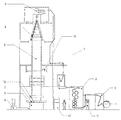
図1には、下流側に接続されているストレッチ設備2と、巻取り機3とを備えたフィルムブロー設備1が示されている。加工しようとするプラスチック顆粒が調量装置を介して押出し機4に供給され、押出し機4において溶融されて均質化され、フィルムブローヘッド5に供給される。多層フィルムの製造時に、層数に応じて複数の押出し機が使用される。フィルムブローヘッド5はリングノズルを有し、リングノズルから押し出されたプラスチック質量体が流出する。フィルムブローヘッド5により、チューブラフィルム6の膨張のために冷却エアーの供給が行われる。プラスチックの硬化後、チューブラフィルム6は平坦化ユニット8において平坦化され、ターン引取部9によって連続的に引き取られ変位される。その後、ブロッキングされたフィルムはストレッチ設備2において機械方向に一軸に延伸される。フィルムは巻取り機3に供給されて巻き取られフィルムロールが形成される。
FIG. 1 shows a film blow facility 1 including a
フィルム厚さ断面の制御のために、フィルムの実際の断面の検出が、有利には二個所で必要である。チューブラフィルム6の周面における厚さ実際断面は、区切られた制御ゾーン7とターン引取部9との間で測定装置10において検出され、延伸されたフィルムのフィルム幅にわたる厚さ実際断面は、ストレッチ設備2と巻取り機3との間で測定装置11において検出される。チューブラフィルム6の厚さ実際断面の測定のための測定装置10は、有利には一定の高さにおいてブローヘッド5上方においてチューブラフィルム6を中心に回るように配置されている。
For the control of the film thickness profile, detection of the actual profile of the film is preferably required at two locations. The actual thickness cross section on the peripheral surface of the
設備制御部12を介して、フィルムブロー工程全体が制御され、特に駆動装置、冷却エアー、冷却リング、フィルムブローヘッド5に位置するか又は下流側に位置する区切られた制御ゾーン7と、チューブラフィルムの引取り速度とを制御する。
The entire film blowing process is controlled via the
測定装置10,11によって測定されたフィルム実際断面は設備制御部12に供給され、目標値/実際値の比較により信号を区切られた制御ゾーン7にさらに送信する。
The actual film cross section measured by the measuring
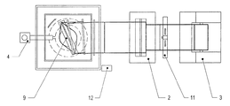
図2には、設備を上方から見た図が示されている。ターン引取部9が各方向(双方向矢印参照)に0〜180°の間において反転運動を実施し、これによりチューブラフィルム6が常に同じエッジにおいて押し合わされない、ということが明確に判る。制御においてこのずれが考慮されない場合には、ブロープロセスにおいてチューブラフィルム6の厚さ断面に刻み付けられる肉薄個所は、平坦化されたフィルムの幅の所定の領域にわたって散逸し、フィルム縁部には存在しないことになる。
The figure which looked at the installation from upper direction is shown by FIG. It can clearly be seen that the turn take-
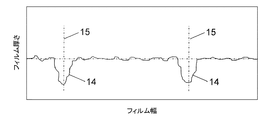
図3には、2つの肉薄個所14を備えたフィルムチューブ(Folienschlauch)の厚さ実際断面が示されている。このような厚さ実際断面は、例えば制御された状態にあるフィルム厚さ測定装置10によって、区切られた制御ゾーン7と平坦化装置8との間において検出される。2つの鎖線15は折り目エッジ(Falzkante)を示している。折り目エッジは平坦化されたフィルムの2つの側方エッジを形成する。2つの肉薄個所14は、フィルムがストレッチ設備2にブロッキングされたチューブとして供給される場合、2つの縁部領域を形成する。
FIG. 3 shows a cross section of the actual thickness of a film tube (Folienschlauch) having two
本発明の前記別の実施の形態において、ブローされ、平坦化されたフィルムチューブは、2つの位置15において切断されて開かれ、2つの平坦なフィルムウェブがそれぞれ別個のストレッチ設備2に供給される。2つの肉薄な領域、つまり図3に記載の肉薄個所14の半部はそれぞれ、ストレッチ設備2に供給されたフィルムの縁部領域を形成する。
In said another embodiment of the present invention, the blown and flattened film tube is cut and opened at two
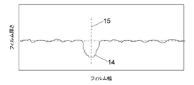
図4には、本発明の第3の実施の形態において使用される、単に1つの肉薄個所14を有するフィルムチューブの厚さ実際断面が示されている。フィルムチューブは肉薄個所14の領域における単に一個所15にのみ沿って切断される。切断されたチューブは次いで平坦なウェブとして開かれ、ストレッチ設備2に供給される。本実施の形態においても肉薄個所14の半部はそれぞれ、ストレッチ設備に供給されたフィルムの縁部領域として見出される。
FIG. 4 shows an actual thickness cross section of a film tube having only one
1 フィルムブロー設備、 2 ストレッチ設備、 3 巻取り機、 4 押出し機、 5 フィルムブローヘッド、 6 チューブラフィルム、 7 区切られた制御ゾーン(自由選択)、 8 平坦化ユニット、 9 ターン引取部、 10 厚さ測定装置、 11 厚さ測定装置、 12 設備制御部、 13 補助制御ユニット(自由選択)、 14 フィルム厚さ断面における肉薄個所、 15 切断個所 DESCRIPTION OF SYMBOLS 1 Film blow equipment, 2 Stretch equipment, 3 Winding machine, 4 Extruder, 5 Film blow head, 6 Tubular film, 7 Divided control zone (free selection), 8 Flattening unit, 9 Turn take-up part, 10 Thickness Thickness measuring device, 11 thickness measuring device, 12 equipment control section, 13 auxiliary control unit (free selection), 14 thin portion in film thickness section, 15 cutting location
Claims (12)
フィルムブロー設備(1)において製造されたチューブラフィルム(6)のフィルム厚さ断面を、ストレッチングにより、フィルム幅全体にわたって平均的なフィルム厚さから可能な限り小さな偏差を有する厚さ横断面を持ったフィルムが製造されるように制御することを特徴とする、延伸されたチューブラフィルムのフィルム厚さを制御する方法。 A method for controlling the film thickness of a stretched tubular film (6), wherein the tubular film (6) is produced in a blow molding process, flattened in a turn take-up section (9), displaced and then stretched In the method for controlling the film thickness of the stretched tubular film, which is uniaxially stretched in the machine direction in the equipment (2),
The film thickness section of the tubular film (6) produced in the film blowing facility (1) has a thickness cross section with the smallest possible deviation from the average film thickness over the entire film width by stretching. A method of controlling the film thickness of a stretched tubular film, characterized in that the film is controlled to be produced.
−フィルムブロー設備(1)のフィルム厚さ断面制御による基本断面と、
−ターン引取部(9)によるチューブラフィルム(6)の変位、及びストレッチプロセスによる干渉によるストレッチ断面と、
−選択的には、フィルムロールの評価に基づくロール断面と、
の重ね合わせから成ることを特徴とする、請求項1から5までのいずれか一項記載のフィルム厚さを制御する方法。 The control algorithm for controlling individual delimited control zones is:
-The basic cross section by the film thickness cross section control of the film blowing equipment (1);
-The displacement of the tubular film (6) by the turn take-up part (9), and the stretch section by interference by the stretch process;
-Optionally, a roll section based on the evaluation of the film roll;
A method for controlling film thickness according to any one of claims 1 to 5, characterized in that it comprises a superposition of:
Priority Applications (1)
| Application Number | Priority Date | Filing Date | Title |
|---|---|---|---|
| JP2010162900A JP5502639B2 (en) | 2010-07-20 | 2010-07-20 | Method for thickness control of stretched blown film |
Applications Claiming Priority (1)
| Application Number | Priority Date | Filing Date | Title |
|---|---|---|---|
| JP2010162900A JP5502639B2 (en) | 2010-07-20 | 2010-07-20 | Method for thickness control of stretched blown film |
Publications (2)
| Publication Number | Publication Date |
|---|---|
| JP2012024941A true JP2012024941A (en) | 2012-02-09 |
| JP5502639B2 JP5502639B2 (en) | 2014-05-28 |
Family
ID=45778493
Family Applications (1)
| Application Number | Title | Priority Date | Filing Date |
|---|---|---|---|
| JP2010162900A Active JP5502639B2 (en) | 2010-07-20 | 2010-07-20 | Method for thickness control of stretched blown film |
Country Status (1)
| Country | Link |
|---|---|
| JP (1) | JP5502639B2 (en) |
Cited By (5)
| Publication number | Priority date | Publication date | Assignee | Title |
|---|---|---|---|---|
| CN108790136A (en) * | 2018-07-05 | 2018-11-13 | 广东科志达机械科技有限公司 | A kind of three-layer thin-film large size inflation film manufacturing machine |
| CN109789628A (en) * | 2016-10-18 | 2019-05-21 | 赖芬豪泽机械工厂有限及两合有限公司 | Method and apparatus for manufacturing plastic film |
| CN112432855A (en) * | 2020-11-25 | 2021-03-02 | 江西捷美软包装有限公司 | Tensile strength detector for high-temperature steaming bag |
| CN112873817A (en) * | 2020-12-24 | 2021-06-01 | 重庆瑞霆塑胶有限公司 | Film cooling forming device for film blowing machine |
| US20240198554A1 (en) * | 2021-02-23 | 2024-06-20 | Albrecht Baumer Gmbh & Co. Kg | Method and installation for producing a film or sheet from a slabstock foam, and method and system for retrofitting an installation for film or sheet production |
Citations (6)
| Publication number | Priority date | Publication date | Assignee | Title |
|---|---|---|---|---|
| JPS5699628A (en) * | 1979-11-23 | 1981-08-11 | Windmoeller & Hoelscher | Method of controlling thickness of film of inflation film extruding device |
| JPH02103121A (en) * | 1988-10-12 | 1990-04-16 | Kao Corp | Preparation of film |
| JPH03189125A (en) * | 1989-12-13 | 1991-08-19 | Windmoeller & Hoelscher | Method for controlling film thickness of tubular film |
| JP2001246668A (en) * | 2000-03-06 | 2001-09-11 | Placo Co Ltd | Method for inflation molding and device therefor |
| JP2004001379A (en) * | 2002-04-19 | 2004-01-08 | Yokogawa Electric Corp | Inflation equipment |
| JP2007245546A (en) * | 2006-03-16 | 2007-09-27 | Yokogawa Electric Corp | Inflation equipment |
-
2010
- 2010-07-20 JP JP2010162900A patent/JP5502639B2/en active Active
Patent Citations (6)
| Publication number | Priority date | Publication date | Assignee | Title |
|---|---|---|---|---|
| JPS5699628A (en) * | 1979-11-23 | 1981-08-11 | Windmoeller & Hoelscher | Method of controlling thickness of film of inflation film extruding device |
| JPH02103121A (en) * | 1988-10-12 | 1990-04-16 | Kao Corp | Preparation of film |
| JPH03189125A (en) * | 1989-12-13 | 1991-08-19 | Windmoeller & Hoelscher | Method for controlling film thickness of tubular film |
| JP2001246668A (en) * | 2000-03-06 | 2001-09-11 | Placo Co Ltd | Method for inflation molding and device therefor |
| JP2004001379A (en) * | 2002-04-19 | 2004-01-08 | Yokogawa Electric Corp | Inflation equipment |
| JP2007245546A (en) * | 2006-03-16 | 2007-09-27 | Yokogawa Electric Corp | Inflation equipment |
Cited By (9)
| Publication number | Priority date | Publication date | Assignee | Title |
|---|---|---|---|---|
| CN109789628A (en) * | 2016-10-18 | 2019-05-21 | 赖芬豪泽机械工厂有限及两合有限公司 | Method and apparatus for manufacturing plastic film |
| CN109789628B (en) * | 2016-10-18 | 2021-07-20 | 莱芬豪舍有限责任两合公司机器制造厂 | Method and apparatus for making plastic films |
| CN108790136A (en) * | 2018-07-05 | 2018-11-13 | 广东科志达机械科技有限公司 | A kind of three-layer thin-film large size inflation film manufacturing machine |
| CN108790136B (en) * | 2018-07-05 | 2024-06-04 | 广东科志达机械科技有限公司 | Large-scale inflation film manufacturing machine of three-layer film |
| CN112432855A (en) * | 2020-11-25 | 2021-03-02 | 江西捷美软包装有限公司 | Tensile strength detector for high-temperature steaming bag |
| CN112432855B (en) * | 2020-11-25 | 2024-05-31 | 江西捷美软包装有限公司 | A high temperature cooking bag tensile strength detector |
| CN112873817A (en) * | 2020-12-24 | 2021-06-01 | 重庆瑞霆塑胶有限公司 | Film cooling forming device for film blowing machine |
| CN112873817B (en) * | 2020-12-24 | 2022-07-15 | 重庆瑞霆塑胶有限公司 | Film cooling forming device for film blowing machine |
| US20240198554A1 (en) * | 2021-02-23 | 2024-06-20 | Albrecht Baumer Gmbh & Co. Kg | Method and installation for producing a film or sheet from a slabstock foam, and method and system for retrofitting an installation for film or sheet production |
Also Published As
| Publication number | Publication date |
|---|---|
| JP5502639B2 (en) | 2014-05-28 |
Similar Documents
| Publication | Publication Date | Title |
|---|---|---|
| CN101954734B (en) | Method for regulating the thickness of stretched blow film | |
| CA2927418C (en) | Method for manufacturing a blown film web as well as a blown film line | |
| JP5920241B2 (en) | Manufacturing method of laminate | |
| JP5502639B2 (en) | Method for thickness control of stretched blown film | |
| US20160052192A1 (en) | Method for regulating the thickness profile of inline-oriented films | |
| EP2514580B1 (en) | Method for regulating the thickness profile of blow films | |
| US20120292818A1 (en) | Device and method for longitudinally stretching a film web | |
| US12157259B2 (en) | Method for starting or terminating production of a film in a film manufacturing machine, film manufacturing machine and computer program product | |
| US12330364B2 (en) | Device and process to permit monoaxial changes in the length of film webs | |
| US20160151950A1 (en) | Apparatus for Producing Films Stretched In-Line | |
| CN116512578B (en) | Method and apparatus for adjusting the thickness of tubular membranes manufactured by membrane blow molding. | |
| JP5409463B2 (en) | Production method and production apparatus for polyolefin resin film for agriculture | |
| US8691132B2 (en) | Heat treatment of thin polymer films | |
| US20220388219A1 (en) | Blown Foil System and Method for Producing a Foil Web | |
| US12544971B2 (en) | Apparatus for the production of inline stretched tubular foils by blowing process | |
| JP2021049741A (en) | Manufacturing method for biaxially oriented films | |
| JP7234556B2 (en) | Method for producing biaxially oriented film | |
| US20140021644A1 (en) | Dies and Methods for Improving Physical Properties of Stretch Film | |
| US11584111B2 (en) | Breathable thermoplastic film with reduced shrinkage | |
| JP2013006655A (en) | Web winding device, web winding method, and method for manufacturing web | |
| RU2773537C2 (en) | Method for correction of film profile on inflatable extrusion lines, corrected film and roll | |
| US9169098B2 (en) | Deviation device for a web of film | |
| EP3647345A1 (en) | Breathable thermoplastic film with reduced shrinkage | |
| JP2000229753A (en) | Film winding method | |
| HK1106949B (en) | Method for producing a polyamide film |
Legal Events
| Date | Code | Title | Description |
|---|---|---|---|
| A621 | Written request for application examination |
Free format text: JAPANESE INTERMEDIATE CODE: A621 Effective date: 20120515 |
|
| A977 | Report on retrieval |
Free format text: JAPANESE INTERMEDIATE CODE: A971007 Effective date: 20130214 |
|
| A131 | Notification of reasons for refusal |
Free format text: JAPANESE INTERMEDIATE CODE: A131 Effective date: 20130319 |
|
| A601 | Written request for extension of time |
Free format text: JAPANESE INTERMEDIATE CODE: A601 Effective date: 20130619 |
|
| A602 | Written permission of extension of time |
Free format text: JAPANESE INTERMEDIATE CODE: A602 Effective date: 20130624 |
|
| A521 | Request for written amendment filed |
Free format text: JAPANESE INTERMEDIATE CODE: A523 Effective date: 20130717 |
|
| A131 | Notification of reasons for refusal |
Free format text: JAPANESE INTERMEDIATE CODE: A131 Effective date: 20130805 |
|
| A601 | Written request for extension of time |
Free format text: JAPANESE INTERMEDIATE CODE: A601 Effective date: 20131105 |
|
| RD03 | Notification of appointment of power of attorney |
Free format text: JAPANESE INTERMEDIATE CODE: A7423 Effective date: 20131108 |
|
| A602 | Written permission of extension of time |
Free format text: JAPANESE INTERMEDIATE CODE: A602 Effective date: 20131108 |
|
| A521 | Request for written amendment filed |
Free format text: JAPANESE INTERMEDIATE CODE: A523 Effective date: 20131204 |
|
| TRDD | Decision of grant or rejection written | ||
| A01 | Written decision to grant a patent or to grant a registration (utility model) |
Free format text: JAPANESE INTERMEDIATE CODE: A01 Effective date: 20140212 |
|
| A61 | First payment of annual fees (during grant procedure) |
Free format text: JAPANESE INTERMEDIATE CODE: A61 Effective date: 20140313 |
|
| R150 | Certificate of patent or registration of utility model |
Ref document number: 5502639 Country of ref document: JP Free format text: JAPANESE INTERMEDIATE CODE: R150 |
|
| R250 | Receipt of annual fees |
Free format text: JAPANESE INTERMEDIATE CODE: R250 |
|
| R250 | Receipt of annual fees |
Free format text: JAPANESE INTERMEDIATE CODE: R250 |
|
| R250 | Receipt of annual fees |
Free format text: JAPANESE INTERMEDIATE CODE: R250 |
|
| R250 | Receipt of annual fees |
Free format text: JAPANESE INTERMEDIATE CODE: R250 |
|
| R250 | Receipt of annual fees |
Free format text: JAPANESE INTERMEDIATE CODE: R250 |
|
| R250 | Receipt of annual fees |
Free format text: JAPANESE INTERMEDIATE CODE: R250 |
|
| R250 | Receipt of annual fees |
Free format text: JAPANESE INTERMEDIATE CODE: R250 |
|
| R250 | Receipt of annual fees |
Free format text: JAPANESE INTERMEDIATE CODE: R250 |
|
| R250 | Receipt of annual fees |
Free format text: JAPANESE INTERMEDIATE CODE: R250 |
|
| R250 | Receipt of annual fees |
Free format text: JAPANESE INTERMEDIATE CODE: R250 |