JP2012024909A - Manipulator control device - Google Patents
Manipulator control device Download PDFInfo
- Publication number
- JP2012024909A JP2012024909A JP2010168650A JP2010168650A JP2012024909A JP 2012024909 A JP2012024909 A JP 2012024909A JP 2010168650 A JP2010168650 A JP 2010168650A JP 2010168650 A JP2010168650 A JP 2010168650A JP 2012024909 A JP2012024909 A JP 2012024909A
- Authority
- JP
- Japan
- Prior art keywords
- manipulator
- force
- control device
- normal
- object surface
- Prior art date
- Legal status (The legal status is an assumption and is not a legal conclusion. Google has not performed a legal analysis and makes no representation as to the accuracy of the status listed.)
- Withdrawn
Links
Images


Landscapes
- Manipulator (AREA)
- Massaging Devices (AREA)
- Finger-Pressure Massage (AREA)
Abstract
【課題】物体表面に対してマニピュレータを適切に作用させる。
【解決手段】直線を含む曲線を有する物体表面上の複数点の位置測定を行う測定手段と、上記物体表面に物理的作用を施すマニピュレータと、上記測定手段による測定データを基に上記マニピュレータを制御する制御手段とからなる。物体表面上の任意の位置測定点の近傍の複数の位置測定点を用いて円弧近似を行う演算部を備え、該演算部は上記円弧近似を行う位置測定点の組合せを前記円弧近似の相関係数が最も高い組合せとして選択し、上記制御手段は演算部で演算された円弧近似によって得られる校正曲線を基にマニピュレータを制御する。
【選択図】図1
A manipulator is made to act appropriately on an object surface.
A measuring means for measuring the position of a plurality of points on an object surface having a curve including a straight line, a manipulator that applies a physical action to the object surface, and the manipulator is controlled based on measurement data obtained by the measuring means. Control means. A calculation unit that performs an arc approximation using a plurality of position measurement points in the vicinity of an arbitrary position measurement point on the object surface, and the calculation unit defines a combination of the position measurement points for performing the arc approximation as a relation of the arc approximation The combination having the highest number is selected, and the control means controls the manipulator based on the calibration curve obtained by the arc approximation calculated by the calculation unit.
[Selection] Figure 1
Description
本発明は、物体の表面形状を測定して該測定結果に基づいて物体表面に対してマニピュレータによる作用を施すマニピュレータ制御装置に関するものである。 The present invention relates to a manipulator control device that measures the surface shape of an object and applies an action by the manipulator to the object surface based on the measurement result.
物体の表面形状の測定には接触方式と非接触方式とがあるが、マニピュレータで物体表面に作用を施すにあたっては、通常、測定結果としての表面座標をプロットして表面形状を求め、プロットした結果に基づいてマニピュレータを作動させている。 There are contact and non-contact methods for measuring the surface shape of an object, but when applying an action to the object surface with a manipulator, the surface coordinates are usually obtained by plotting the surface coordinates as the measurement results, and the plotted results The manipulator is operated based on the above.
たとえば、マニピュレータが人体表面に対してマッサージ作用を及ぼす施療子である場合、つまりマニピュレータ制御装置がマッサージ機である場合、特開2001−120621号公報(特許文献1)には圧力センサを備えた施療子を人体に接触させつつ上下に動かすとともに上下方向位置及び接触方向(前後方向)位置を別途エンコーダで検出することで人体の上下方向における表面形状(体形ライン)を計測することが示されている。この場合、エンコーダの分解能に従った間隔で接触点の位置座標を求めて、各接触点の位置座標をプロットすることで表面形状を求めていることになる。そして分解能を細かくすればするほど、プロットした表面形状は物体表面形状に一致するものとなる。 For example, when the manipulator is a treatment element that exerts a massaging action on the surface of the human body, that is, when the manipulator control device is a massage machine, Japanese Patent Application Laid-Open No. 2001-120621 (Patent Document 1) is provided with a pressure sensor. It is shown that the surface shape (body shape line) in the vertical direction of the human body is measured by moving the child up and down while making contact with the human body and separately detecting the vertical position and the contact direction (front-rear direction) position with an encoder. . In this case, the position coordinates of the contact points are obtained at intervals according to the resolution of the encoder, and the surface shape is obtained by plotting the position coordinates of each contact point. The finer the resolution, the more the plotted surface shape matches the object surface shape.
しかしながら分解能を細かくしたところで、得られた接触点の位置座標は位置を示すだけであるために、曲面である物体表面に対して法線方向からマニピュレータで作用を施したいことがあってもこれに対応することができない。 However, since the position coordinates of the obtained contact point only indicate the position when the resolution is made fine, even if you want to apply an action to the curved object surface from the normal direction with a manipulator I can't respond.
被施療者の前面側を支持する支持体と、支持体後方に配設されて被施療者の背面を施療子でマッサージする施療手段とからなるとともに、上記支持体で支持された被施療者の身体外形状を計測する外形状計測手段を備えて、上記施療手段が上記外形状計測手段から得られた身体外形状データに基づいて施療子の動作を規定する制御部を備えたマッサージ装置が特開2009−160175号公報(特許文献2)で提案されているが、ここでの身体外形状データも上記のものと同様に位置を示すだけである。 A support body that supports the front side of the user, and treatment means that is disposed behind the support body and massages the back surface of the user with a treatment element. Specially provided is a massage apparatus comprising an external shape measuring means for measuring an external shape, and a control unit for the treatment means to regulate the operation of the treatment element based on the external shape data obtained from the external shape measurement means. This is proposed in Japanese Unexamined Patent Application Publication No. 2009-160175 (Patent Document 2), but the extracorporeal body shape data here also only indicates the position as described above.
ちなみに、上記のようなマッサージ機の場合、マニピュレータである施療子が人体表面を押圧するにあたり、人体表面に対してその法線方向以外から押圧すると、マッサージが有効に働かないだけでなく痛みを誘発する場合がある。 By the way, in the case of the massage machine as described above, when the treatment element, which is a manipulator, presses the human body surface, if the human body surface is pressed from other than the normal direction, the massage does not work effectively but also induces pain. There is a case.
マニピュレータが物体表面に切削加工を施す切削具である場合、物体表面の接線方向を認識して切削具を移動させないと、切削具が物体に噛み込んでしまう場合がある。 When the manipulator is a cutting tool that performs cutting on the object surface, the cutting tool may bite into the object unless the tangential direction of the object surface is recognized and the cutting tool is moved.
本発明は上記の点に鑑みなされたものであって、物体表面に対してマニピュレータを適切に作用させることができるマニピュレータ制御装置を提供することを課題とするものである。 This invention is made | formed in view of said point, Comprising: It aims at providing the manipulator control apparatus which can make a manipulator act on an object surface appropriately.
本発明は、直線を含む曲線を有する物体表面上の複数点の位置測定を行う測定手段と、上記物体表面に物理的作用を施すマニピュレータと、上記測定手段による測定データを基に上記マニピュレータを制御する制御手段とからなるマニピュレータ制御装置において、前記物体表面上の任意の位置測定点の近傍の複数の位置測定点を用いて円弧近似を行う演算部を備えるとともに、該演算部は上記円弧近似を行う位置測定点の組合せを前記円弧近似の相関係数が最も高い組合せとして選択するものであり、上記制御手段は上記演算部で演算された円弧近似によって得られる校正曲線を基に上記マニピュレータを制御するものであることに特徴を有している。 The present invention provides a measuring means for measuring the position of a plurality of points on an object surface having a curve including a straight line, a manipulator for applying a physical action to the object surface, and controlling the manipulator based on measurement data obtained by the measuring means. A manipulator control device comprising a control means for performing arc approximation using a plurality of position measurement points in the vicinity of an arbitrary position measurement point on the object surface, and the calculation unit performs the arc approximation described above. The combination of position measurement points to be performed is selected as the combination having the highest correlation coefficient of the arc approximation, and the control means controls the manipulator based on the calibration curve obtained by the arc approximation calculated by the calculation unit. It is characterized by what it does.
物体表面を位置測定点の群としてではなく、円弧近似で得た校正曲線で表現されるものとして扱うものであり、また相関係数が高い位置測定点の組み合わせから校正曲線を決定するようにしたものである。 The surface of the object is treated not as a group of position measurement points but as a calibration curve obtained by arc approximation, and the calibration curve is determined from the combination of position measurement points with a high correlation coefficient. Is.
上記演算部は、円弧近似によって得られる校正曲線で表現できる複数の位置測定点を除いた残りの位置測定点の中で、任意の位置測定点の近傍の複数の位置測定点を用いて円弧近似を行うことを繰り返して行うものであると、物体表面形状全体を複数の円弧近似の組合せで表現することができる。 The arithmetic unit uses a plurality of position measurement points in the vicinity of an arbitrary position measurement point among the remaining position measurement points excluding a plurality of position measurement points that can be expressed by a calibration curve obtained by arc approximation. If the process is repeated, the entire object surface shape can be expressed by a combination of a plurality of arc approximations.
上記制御手段は、校正曲線を算出した物体表面上の任意の点を通る法線上に上記の点から一定距離だけ離れた位置に前記マニピュレータを移動させた後、上記法線の方向に沿って前記マニピュレータを移動させて物体表面に物理的作用を施すものであることが物体表面にその法線方向から物理的作用を施すことができる点で好ましく、この時、少なくとも異なる2軸方向の力を各々検出できる力センサを前記マニピュレータの先端部に備えているとともに、上記力センサによる各軸の力検出値を前記法線方向へ斜影した合力を演算する合力演算部を備えておれば、物体表面にその法線方向から及ぼす力を容易に算出することができる。 The control means moves the manipulator to a position away from the point by a certain distance on a normal passing through an arbitrary point on the object surface where the calibration curve is calculated, and then moves the manipulator along the direction of the normal. It is preferable that a physical action is applied to the object surface by moving the manipulator from the viewpoint that the physical action can be applied to the object surface from the normal direction. If a force sensor capable of detecting is provided at the tip of the manipulator and a resultant force calculation unit that calculates a resultant force obtained by obliquely projecting the force detection value of each axis by the force sensor in the normal direction, The force exerted from the normal direction can be easily calculated.
上記マニピュレータ先端部の向きを上記法線方向に合わせた状態で上記法線の方向に沿って上記マニピュレータを移動させて物体表面に物理的作用を施すものであってもよく、この場合、物体表面にその法線方向から物理的作用を施すことがより確実に行うことができる。また、前記法線方向の力を検出できる力センサを前記マニピュレータの先端部に備えていると、法線方向から物体表面に及ぼす力を1軸の力センサで検出することができる。 The manipulator may be moved along the direction of the normal while the tip of the manipulator is aligned with the direction of the normal to apply a physical action to the object surface. It is possible to more reliably perform physical action from the normal direction. Further, when a force sensor capable of detecting the force in the normal direction is provided at the tip of the manipulator, the force exerted on the object surface from the normal direction can be detected by a uniaxial force sensor.
さらに前記法線方向の力と、前記法線方向と直交する平面内において直交する2軸方向の力を各々独立に検出する力センサを前記マニピュレータの先端部に備えているとともに、上記直交する2軸方向の力の値の比から物体の表面下の状態を推定する推定部を備えていると、たとえば物体が人体であり、マニピュレータがマッサージ用の施療子である場合など、人体皮膚下にある筋繊維の方向を的確に推定することができる。 Furthermore, a force sensor for independently detecting the force in the normal direction and the force in the biaxial direction orthogonal to each other in a plane orthogonal to the normal direction is provided at the tip of the manipulator, and the orthogonal 2 With an estimation unit that estimates the subsurface state of an object from the ratio of axial force values, for example, when the object is a human body and the manipulator is a massage treatment device, it is under the human skin. The direction of muscle fibers can be estimated accurately.
本発明においては、物体表面を円弧近似で得た校正曲線で表現されるものとして扱うために、物体表面の法線方向や接線方向にマニピュレータを制御することも容易に且つ確実に行える上に、物体表面上の実際には位置測定をしていない点でもその位置を特定することができるものであり、特に円弧近似を行うにあたり、相関係数が高い位置測定点の組み合わせから校正曲線を決定することから、物体表面形状を的確に表現した校正曲線を基にマニピュレータを制御することができる。 In the present invention, in order to treat the object surface as expressed by a calibration curve obtained by arc approximation, the manipulator can be easily and reliably controlled in the normal direction or tangential direction of the object surface. It is possible to specify the position of a point on the object surface that is not actually measured, and determine the calibration curve from the combination of position measurement points with a high correlation coefficient, especially when performing arc approximation. Therefore, the manipulator can be controlled based on the calibration curve that accurately represents the object surface shape.
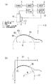
本発明を実施の形態の一例に基づいて詳述すると、図1に示す例においては、物体9の表面に物理的作用を施すマニピュレータ1の先端部に、レーザを用いた非接触式の距離測定器2を設置してある。また、上記マニピュレータ1を物体9の表面に沿った方向に動かす駆動部10にはマニピュレータ1の物体9の表面に沿った方向の位置データを出力するエンコーダ等からなる位置データ出力部11を設けてある。
The present invention will be described in detail based on an example of an embodiment. In the example shown in FIG. 1, a non-contact type distance measurement using a laser at a tip portion of a
物体9の表面形状の測定は、上記マニピュレータ1及び距離測定器2を物体9の表面に沿った方向(図中の矢印方向)に駆動部10によって動かしつつ、距離測定器2で距離測定器2から物体9表面までの距離を測定する。この時、該距離測定器2からの距離情報と、上記位置データ出力部11からの位置データとに基づいて物体9の表面の測定点における位置座標を位置座標算出部12が算出する。つまり、本例においては、位置データ出力部11とレーザ距離測定器2と位置座標算出部12とで物体表面の位置測定を行う測定手段が構成されていることになる。なお、距離測定器としてここでは非接触式の距離測定器2を例にあげたが、接触式の距離測定器であってもよく、物体表面を撮影したステレオ画像から物体表面の位置座標を求めるものであってもよい。本発明は測定手段の構成を問わないものである。
The surface shape of the
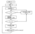
上記測定手段で測定された物体9の表面の各測定点を順次k1,k2,k3…で表す点群とすると、これら測定点の位置座標はいったん記憶部3に記憶され、ついで演算部4が各測定点の位置座標を順次読み出して順次円弧近似を行う。この円弧近似は、まず連続する3点の測定点(k1〜k3)で行って円弧近似した校正曲線の相関係数r3を算出する。ついで、次の測定点を含む4点の測定点(k1〜k4)の円弧近似を行って、その円弧近似した校正曲線の相関係数r4を算出し、先に求めた校正曲線の相関係数r3と後の校正曲線の相関係数r4とを比較し、後者の相関係数r4の方が高ければ、さらに次の測定点を含む5点の測定点(k1〜k5)の円弧近似を行って、円弧近似した校正曲線の相関係数r5を算出し、先に求めた校正曲線の相関係数r4と後の校正曲線の相関係数r5とを比較するということを、測定点が多い方の校正曲線の相関係数が低くなるまで続ける。
If each measurement point on the surface of the
つまり、n点の測定点(k1〜kn)までの校正曲線の相関係数rkが、n+1点の測定点(k1〜kn+1)までの校正曲線の相関係数rk+1より高ければ、k〜knまでの測定点を単一の校正曲線C1=R2=(X−a)2+(Z−b)2で表す近似区間S1とする。 That is, if the correlation coefficient rk of the calibration curve up to n measurement points (k1 to kn) is higher than the correlation coefficient rk + 1 of the calibration curve up to n + 1 measurement points (k1 to kn + 1), k to kn. Is an approximate interval S1 represented by a single calibration curve C1 = R 2 = (X−a) 2 + (Z−b) 2 .
そして、n+1点の測定点を次の新たなk1点とし、上述のように、円弧近似する点群の組合せ数を少なくとも3点以上の組合せから逐次計算し、その都度、その円弧近似した校正曲線の相関係数を算出するとともに、算出した相関係数が最も高くなる区間を近似区間S2として、その区間に該当する点群については当該近似曲線(校正曲線C2)を用いて形状を表現する。 Then, n + 1 measurement points are set as the next new k1 points, and as described above, the number of combinations of point groups to be approximated by arcs is sequentially calculated from combinations of at least 3 points, and each time the calibration curve approximated by the arcs is calculated. The correlation coefficient is calculated, and the section where the calculated correlation coefficient is the highest is the approximate section S2, and the shape of the point group corresponding to the section is expressed using the approximate curve (calibration curve C2).
このようにして図2に示すように近似区間S1,S2,S3…を順次決定するとともに各近似区間S1,S2,S3…についての校正曲線C1,C2,C3…を順次決定して、物体9の表面形状を複数の円弧近似の組み合わせとなる関数で表現するのである。図3に上記動作のフローチャートを示す。 In this way, as shown in FIG. 2, the approximation sections S1, S2, S3... Are sequentially determined, and the calibration curves C1, C2, C3. The surface shape is expressed by a function that is a combination of a plurality of circular arc approximations. FIG. 3 shows a flowchart of the above operation.
円弧近似できた区間においては、測定点と次の測定点の間のように実際に測定していない点でも物体表面の位置を特定して把握することができることになる。特に形状を複数の円弧で近似して、円弧近似した際の相関係数が最も高くなる形状点群の組合せを採用するために、物体9の実際の表面形状に最も近似する円弧を簡便に求めることができる。
In the section in which the arc can be approximated, the position of the object surface can be identified and grasped even at a point that is not actually measured, such as between the measurement point and the next measurement point. In particular, the shape is approximated by a plurality of arcs, and the arc closest to the actual surface shape of the
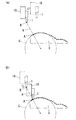
物体9の表面形状を表す校正曲線を得たならば、マニピュレータ1の動きを制御する制御部5は、物体9の表面のA点にマニピュレータ1で物理的作用を及ぼすにあたり、図4に示すように、A点を含む校正曲線Cから物体9表面のA点の法線ベクトルHを求めてこの法線ベクトルH上でA点から一定距離だけ離されたプリアプローチポイントBにマニピュレータ1を移動させ、この後、上記法線ベクトルHに沿ってマニピュレータ1を移動させることでA点に物理的作用を及ぼすものとする。
When the calibration curve representing the surface shape of the
ここで、上記プリアプローチポイントBからA点に向けてマニピュレータ1を移動させた場合、マニピュレータ1のフランジ面と、物体9表面上の対象点Aにおける法線ベクトルHとが一致していないために、プリアプローチポイントBから法線ベクトルHに沿って物体9に接触させた際に、フランジ面に作用する力から物体9に作用する力を直接検出することはできない。
Here, when the
このために、マニピュレータ1先端部に少なくとも異なる2軸方向X,Zの力を各々検出できる力センサを設けて、各軸の力検出値Fx,Fzから前記法線方向に斜影した合力Fを演算する演算部を備えたものとしておくことが、法線方向に所望の力を作用させる点において有効である。また、マニピュレータ1が物体9表面に圧力を加えるものである場合、マニピュレータ1における物体9との接触面は半球状としておくことが好ましい。
For this purpose, a force sensor capable of detecting at least two different forces in the two axial directions X and Z is provided at the tip of the
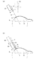
マニピュレータ1として、その向きを変更することができるものを用いる場合は、図6に示すように、プリアプローチポイントBにマニピュレータ1を移動させた際にマニピュレータ1の向きを対象点Aの法線方向Hと一致させ、その後、マニピュレータ1のフランジ面の法線方向、すなわち物体対象点Aの法線方向Hに沿ってマニピュレータ1を移動させるのが好ましい。
When using a
マニピュレータ1のフランジ面に作用する力と物体9の法線方向Hに作用する力とが常に一致するために、物体9の法線方向へ作用させる力の制御が容易となると同時に、マニピュレータ1のフランジ面に1軸の力センサを設置するだけで、物体9の表面に法線方向から作用させる力を正確に検出することができる。
Since the force acting on the flange surface of the
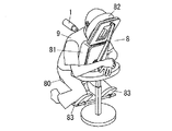
次に本マニピュレータ制御装置をマッサージ機に応用した場合について説明する。この場合の物体9は人体に相当することになり、人体に物理的作用を及ぼす施療子がマニピュレータ1に相当することになる。また、通常のマッサージ機は、椅子の背もたれ内などの人体表面を支える部材内にマッサージ機構を組み込んで上記部材によって支えられている人体表面(通常は背面)に施療子がマッサージを施すことになるが、ここでのマッサージ機は、図7に示すように、前面側が支持体8によって支持されている人体の背面をマッサージするものとする。
Next, the case where this manipulator control apparatus is applied to a massage machine will be described. The
図示例における支持体8は、着座部80と、人体の胸部前面を支える胸部支持部81と、人体の頭部前面側を支える頭部支持部82と、膝を載せるための膝当て部83と、上腕を載せるための上腕置き部84とを備えたものとして構成されており、上記頭部支持部82は呼吸を妨げることがないように抜き孔が中央に設けられている。そして、この支持体8においては、被施療者が着座部80に座るとともに胸部支持部81に胸を当て、更に頭部支持部82に顔を当てれば、被施療者は前傾姿勢を保った状態で支持体8に支持される。マニピュレータ(施療子)1は、この状態で支持されている人体背面に力を加えることでマッサージを行う。
The
施療子であるマニピュレータ1としては、その向きを変更することができないものであってもよいが、次に述べる筋繊維方向の推定という点において、向きを変更することができるもの、つまり、図6に示したものを好適に用いることができる。
The
人体表面に対して垂直な方向に力を加えつつ筋繊維方向に垂直方向(で且つ体表面に沿った方向)に筋繊維方向を引っ張る動作が理想的なマッサージと言われており、実際にも施療効果だけでなく官能的にも好ましいものとなっている。 The action of pulling the muscle fiber direction in the direction perpendicular to the muscle fiber direction (and the direction along the body surface) while applying force in the direction perpendicular to the human body surface is said to be an ideal massage. Not only the treatment effect but also sensory is preferable.
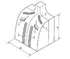
このマッサージを実現するにあたっては、人体の部位によって筋繊維の方向が異なることから、今から施療する部位の筋繊維の方向を特定する必要がある。図8は肩高さh、体幅w、曲率半径rの曲面で人体背面をモデル化したものにおいて、各部位の筋繊維7の方向を示している。
In realizing this massage, it is necessary to specify the direction of the muscle fiber of the part to be treated from now because the direction of the muscle fiber differs depending on the part of the human body. FIG. 8 shows the direction of the
この筋繊維7の方向を特定するにあたり、本出願人は特開2009−160175号公報において、マニピュレータ1に設けた力センサの出力から行うことを提案した。
In specifying the direction of the
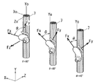
すなわち、力センサとして、3軸方向の力Fx,Fy,Fzを検出することができるとともに、施療子1の動きの3軸方向X,Y,Zと上記力Fx,Fy,Fzの方向とを一致させたものを用いるものとし、施療子1(図9では拇指を模した形状としている)を人体に向けて移動させる方向をZ、筋をほぐすために施療子1を人体表面に沿って動かす方向をXとすると、施療子1を人体に押し付けた状態で上記X方向に施療子1を動かした時、反力としての力Fx,Fy,Fzを力センサで検出することができる。
That is, as the force sensor, the forces Fx, Fy, and Fz in the three axes can be detected, and the three axes X, Y, and Z of the movement of the
ここで、ある部位下に存在する筋繊維7の方向をYo、体表面に沿った面内における筋繊維方向Yoと直交する方向をXoとする時、施療子1を人体表面に沿って動かす方向Xを筋繊維方向Yoに対してθ=90°の方向(=直交方向Xo)とする時、力センサで検出されるFx,Fyの値は、Fxの値がFyの値よりも十分大きくなる。
Here, when the direction of the
そして施療子1を動かす方向XのYo方向からの角度θを小さくしていくにつれて、Fxの値がFyの値に接近したものとなる。つまり、Fxの値とFyの値の比が最も大きくなる方向Xが、筋繊維方向Yoと直交する方向Xoとなる。
Then, as the angle θ from the Yo direction of the direction X in which the
また、Fxの値が大きくなるまで施療子1を動かす方向Xを変化させなくても、Fxの値とFyの値の比を基に上記θの値を求めることができ、上記方向Xと角度θから筋繊維方向Yo及びこれに直交する方向Xoを推定することができる。そしてこの推定結果に基づいて施療子1を動かす方向Xを規定することで、好ましいとされているマッサージをより正確に行うことができる。
Further, the θ value can be obtained based on the ratio between the Fx value and the Fy value without changing the direction X in which the
ここにおいて、前述のようにマニピュレータ(施療子)1の向きを物体(人体)9の表面の法線方向Hに合わせることができるものを用いた場合、痛覚が少ない指圧を行うことができるだけでなく、上記筋繊維方向Yoを推定して筋繊維方向と直交する方向にマニピュレータ1を往復動させる揉捏マッサージを行うことで筋繊維をほぐすにあたり、力センサから出力されるFx,Fyの値をそのまま上記の筋繊維方向の推定のために用いることができるものであり、マニピュレータ1を物体9の表面の法線方向以外から力を加える場合に比して、物体の法線方向と接平面内の力を演算で算出する作業が不要となるだけでなく、無用なノイズが入らないために、筋繊維方向の推定の精度をきわめて高く保つことができる。
Here, as described above, when using the one that can align the direction of the manipulator (treatment element) 1 with the normal direction H of the surface of the object (human body) 9, not only can acupressure with less pain sensation be performed. When the muscle fiber is loosened by performing acupuncture massage by reciprocating the
また、マニピュレータ1を法線方向から作用させることができる場合、上記のような筋繊維方向の推定を行わない場合においても、1軸の力センサで物体の法線方向に所望の力を作用させることが可能となる。
Further, when the
マッサージ機を具体例として示したが、本発明に係るマニピュレータ制御装置は、このような例に限定されるものではない。たとえば、液晶分子の配向を行うラビング装置にも用いることができる。この場合、曲率を有する液晶面においても一定の押付力で配向を行うことが可能であるために、平面に限られる現状の液晶面とは異なる形状の液晶を製作することができる。 Although the massage machine is shown as a specific example, the manipulator control device according to the present invention is not limited to such an example. For example, it can be used for a rubbing apparatus for aligning liquid crystal molecules. In this case, since it is possible to perform orientation with a constant pressing force even on a liquid crystal surface having a curvature, a liquid crystal having a shape different from that of the current liquid crystal surface limited to a flat surface can be manufactured.
1 マニピュレータ
2 距離測定器
9 物体
11 位置データ出力部
12 位置座標算出部
DESCRIPTION OF
Claims (7)
Priority Applications (1)
| Application Number | Priority Date | Filing Date | Title |
|---|---|---|---|
| JP2010168650A JP2012024909A (en) | 2010-07-27 | 2010-07-27 | Manipulator control device |
Applications Claiming Priority (1)
| Application Number | Priority Date | Filing Date | Title |
|---|---|---|---|
| JP2010168650A JP2012024909A (en) | 2010-07-27 | 2010-07-27 | Manipulator control device |
Publications (1)
| Publication Number | Publication Date |
|---|---|
| JP2012024909A true JP2012024909A (en) | 2012-02-09 |
Family
ID=45778472
Family Applications (1)
| Application Number | Title | Priority Date | Filing Date |
|---|---|---|---|
| JP2010168650A Withdrawn JP2012024909A (en) | 2010-07-27 | 2010-07-27 | Manipulator control device |
Country Status (1)
| Country | Link |
|---|---|
| JP (1) | JP2012024909A (en) |
Cited By (3)
| Publication number | Priority date | Publication date | Assignee | Title |
|---|---|---|---|---|
| WO2014199414A1 (en) * | 2013-06-13 | 2014-12-18 | テルモ株式会社 | Medical manipulator, and control method therefor |
| KR101580935B1 (en) * | 2014-08-18 | 2015-12-30 | 연세대학교 산학협력단 | Real-time ssd output system for linear accelerator |
| JP2017185175A (en) * | 2016-04-04 | 2017-10-12 | ゆかり 和田 | Automatic acupressure apparatus |
-
2010
- 2010-07-27 JP JP2010168650A patent/JP2012024909A/en not_active Withdrawn
Cited By (5)
| Publication number | Priority date | Publication date | Assignee | Title |
|---|---|---|---|---|
| WO2014199414A1 (en) * | 2013-06-13 | 2014-12-18 | テルモ株式会社 | Medical manipulator, and control method therefor |
| JPWO2014199414A1 (en) * | 2013-06-13 | 2017-02-23 | テルモ株式会社 | Medical manipulator and method of operating the same |
| US9844416B2 (en) | 2013-06-13 | 2017-12-19 | Terumo Kabushiki Kaisha | Medical manipulator and method of controlling the same |
| KR101580935B1 (en) * | 2014-08-18 | 2015-12-30 | 연세대학교 산학협력단 | Real-time ssd output system for linear accelerator |
| JP2017185175A (en) * | 2016-04-04 | 2017-10-12 | ゆかり 和田 | Automatic acupressure apparatus |
Similar Documents
| Publication | Publication Date | Title |
|---|---|---|
| CN106726468B (en) | Method and system for accurately positioning massage acupuncture points | |
| JP5449762B2 (en) | Chair type massage machine | |
| US6749577B2 (en) | Massage machine | |
| Jarrasse et al. | A methodology to quantify alterations in human upper limb movement during co-manipulation with an exoskeleton | |
| US20100286569A1 (en) | Massage apparatus | |
| JP2009005775A (en) | Massage machine | |
| JP2012024909A (en) | Manipulator control device | |
| JP6458979B2 (en) | Body condition evaluation device | |
| CN107174468A (en) | Organism state evaluating apparatus and massager | |
| WO2009118933A1 (en) | Massage robot and control program thereof | |
| JP7187197B2 (en) | Massage machine | |
| US20190184574A1 (en) | Systems and methods for automated rehabilitation | |
| JP5097907B2 (en) | Massage robot, its control program, and body part identification robot | |
| US20220054355A1 (en) | Body care motion tracking device and body care management method using same | |
| Luo et al. | Tapping motion detection incorporate with impedance control of robotics tapotement massage on human tissue | |
| JP4062241B2 (en) | Massage machine | |
| CN102988148B (en) | Massager | |
| JP2012024495A (en) | Massage equipment | |
| JP2005006735A (en) | Massage machine | |
| JP4696784B2 (en) | Massage machine | |
| JP6319658B2 (en) | Massage machine | |
| JP4600459B2 (en) | Massage machine | |
| KR102872120B1 (en) | Massage chair with method that position of hand massage module can be adjusted according to user's arm length | |
| KR102303247B1 (en) | Load-indicating device of the massage | |
| JP2007014458A (en) | Massage machine |
Legal Events
| Date | Code | Title | Description |
|---|---|---|---|
| A711 | Notification of change in applicant |
Free format text: JAPANESE INTERMEDIATE CODE: A712 Effective date: 20120118 |
|
| A300 | Withdrawal of application because of no request for examination |
Free format text: JAPANESE INTERMEDIATE CODE: A300 Effective date: 20131001 |