JP2012024907A - Cutting method and cutting tool - Google Patents
Cutting method and cutting tool Download PDFInfo
- Publication number
- JP2012024907A JP2012024907A JP2010168384A JP2010168384A JP2012024907A JP 2012024907 A JP2012024907 A JP 2012024907A JP 2010168384 A JP2010168384 A JP 2010168384A JP 2010168384 A JP2010168384 A JP 2010168384A JP 2012024907 A JP2012024907 A JP 2012024907A
- Authority
- JP
- Japan
- Prior art keywords
- cutting
- tool
- work material
- cutting tool
- spindle
- Prior art date
- Legal status (The legal status is an assumption and is not a legal conclusion. Google has not performed a legal analysis and makes no representation as to the accuracy of the status listed.)
- Pending
Links
- 238000005520 cutting process Methods 0.000 title claims abstract description 140
- 238000000034 method Methods 0.000 title claims abstract description 23
- 239000000463 material Substances 0.000 claims abstract description 29
- 239000002184 metal Substances 0.000 abstract description 2
- 239000002699 waste material Substances 0.000 description 3
- 230000000694 effects Effects 0.000 description 2
- 230000020169 heat generation Effects 0.000 description 2
- 230000003247 decreasing effect Effects 0.000 description 1
- 238000003754 machining Methods 0.000 description 1
- 238000003672 processing method Methods 0.000 description 1
Images
Landscapes
- Turning (AREA)
Abstract
【課題】容易かつ安価な構成によって、長尺な切削屑や厚い切削屑を発生させることなく高い加工精度で被削材の切削加工を実施することが可能な切削加工方法を提供する。
【解決手段】切削加工用工具1は、金属によって略円柱状に形成されており、前方から見ると、複数の突条と凹溝とが連続した波状の凹凸を形成した状態になっている。また、切削加工用工具1の前端の刃先面には、複数の凸部と凹部とが中心軸に対する放射方向に交互に設けられており、側方から見ると、それらの凸部と凹部とが連続した波状の凹凸を形成した状態になっている。かかる切削加工用工具1によって被削材Wを切削する際には、被削材Wを主軸14を中心として回転させた状態で、工具主軸15を中心として回転させた切削加工用工具1をアプローチさせる。
【選択図】図2The present invention provides a cutting method capable of cutting a work material with high processing accuracy without generating long cutting scraps or thick cutting scraps with an easy and inexpensive configuration.
A cutting tool 1 is formed in a substantially cylindrical shape from a metal, and when viewed from the front, is in a state in which a plurality of ridges and concave grooves form wave-like irregularities. In addition, a plurality of convex portions and concave portions are alternately provided in the radial direction with respect to the central axis on the cutting edge surface of the front end of the cutting tool 1, and when viewed from the side, these convex portions and concave portions are provided. It is in a state where continuous wavy irregularities are formed. When cutting the workpiece W with the cutting tool 1, the cutting tool 1 rotated about the tool spindle 15 in the state where the workpiece W is rotated about the spindle 14 is approached. Let
[Selection] Figure 2
Description
本発明は、旋盤等の切削加工機における被削材の切削加工方法、および、その切削加工方法に適した工具に関するものである。 The present invention relates to a cutting method for a work material in a cutting machine such as a lathe and a tool suitable for the cutting method.
旋盤等の切削加工機を利用して主軸周りに回転する切削材に切削工具によって切削加工を施す場合には、切削材料によっては、厚い切削屑が形成されて切削抵抗が大きくなったり、切削屑が伸びて絡まる等の不具合が生じることがある。それゆえ、切削抵抗を低減させ、切削屑の厚みを減少させる目的で、特許文献1の如く、切削工具の近傍にアクチュエータを設けて、当該アクチュエータを利用して、切削時に切削方向あるいは切屑流出方向の振動を与える、いわゆる振動切削という加工方法が考案されている。
When a cutting tool such as a lathe is used to cut the cutting material that rotates around the main axis with a cutting tool, depending on the cutting material, thick cutting chips may be formed and the cutting resistance may be increased. May cause problems such as stretching and tangling. Therefore, for the purpose of reducing cutting resistance and reducing the thickness of the cutting waste, an actuator is provided in the vicinity of the cutting tool as in
しかしながら、上記の如く切削時にアクチュエータによる振動を与える切削加工方法は、切削工具の刃先と被削材との間の摩擦力の増大を防止することが可能であるものの、切削加工中に専用のアクチュエータによって常に振動を付与し続ける必要があるため、加工コストが高くなってしまう。また、アクチュエータから生じる振動が大きすぎると、加工の精度が悪くなる、という不具合もある。 However, although the cutting method for applying vibration by the actuator during cutting as described above can prevent an increase in the frictional force between the cutting edge of the cutting tool and the work material, a dedicated actuator is used during the cutting process. Therefore, it is necessary to keep applying vibration constantly, which increases the processing cost. In addition, there is a problem that if the vibration generated from the actuator is too large, the processing accuracy is deteriorated.
本発明の目的は、上記従来の切削加工方法が有する問題点を解消し、容易かつ安価な構成によって、長尺な切削屑や厚い切削屑を発生させることなく高い加工精度で被削材の切削加工を実施することが可能な切削加工方法を提供することにある。加えて、そのような切削加工に適した切削加工用の工具を提供することにある。 The object of the present invention is to eliminate the problems of the conventional cutting method described above, and to cut a work material with high processing accuracy without generating long cutting scraps or thick cutting scraps by an easy and inexpensive configuration. It is providing the cutting method which can implement a process. In addition, it is to provide a cutting tool suitable for such cutting.
本発明の内、請求項1に記載された発明は、主軸を中心として回転させた被削材に対して、工具主軸を中心として回転させた工具をアプローチさせることにより、被削材に切削加工を施す切削加工方法であって、前記工具が円柱状のものであり、刃先面あるいは刃先の外周に、連続した波状の凹凸が形成されていることを特徴とするものである。
Among the present inventions, the invention described in
請求項2に記載された発明は、請求項1に記載された発明において、前記工具の刃先面あるいは刃先の外周の凹凸が、正弦波状のものであることを特徴とするものである。なお、刃先面の凹凸が正弦波状のものであるとは、工具の長さ方向における所定の位置における外周の円を基準線とした場合に、凹凸を形成している輪郭線の位置(y)が基準線上の位置(θ)に対してy=A・sin(pθ)(A,pは任意の定数)の関係にあることを意味し、刃先の外周の凹凸が正弦波状のものであるとは、工具の軸心から所定の距離にある円を基準線とした場合に、凹凸を形成している輪郭線の位置(y)が基準線上の位置(θ)に対してy=B・sin(qθ)(A,qは任意の定数)の関係にあることを意味する。
The invention described in
請求項3に記載された発明は、主軸を中心として回転させた被削材に対して、工具主軸を中心として回転させた工具をアプローチさせることにより、被削材に切削加工を施す際に用いる工具であって、円柱状に形成されており、刃先面あるいは刃先の外周に、連続した波状の凹凸が形成されていることを特徴とするものである。
The invention described in
請求項1の切削加工方法によれば、刃先面あるいは刃先の外周に連続した波状の凹凸を形成してなる円柱状の工具を用いるだけの容易かつ安価な構成によって、切削加工中に工具および被削材に主分力方向(工具による切削方向に沿った方向)あるいは送り分力方向(工具による切削方向と直交する方向)の連続した振動を与えることが可能となる。したがって、請求項1の切削加工方法によれば、工具の刃先と被削材との間の摩擦力を効果的に低減させることができるため、切削屑の長さや厚さを減少させることができる上、加工時の発熱や抵抗の増大を抑えて加工精度を向上させることが可能となる。
According to the cutting method of the first aspect of the present invention, the tool and the workpiece can be removed during the cutting process by an easy and inexpensive configuration that simply uses a cylindrical tool formed by forming wavy irregularities on the cutting edge surface or the outer periphery of the cutting edge. It becomes possible to give continuous vibration in the main component force direction (direction along the cutting direction by the tool) or feed component force direction (direction orthogonal to the cutting direction by the tool) to the work material. Therefore, according to the cutting method of
請求項2の切削加工方法によれば、工具の刃先と被削材との間の摩擦力をより効果的に低減させることが可能となる。
According to the cutting method of
請求項3の切削加工用工具によれば、非常に容易にかつ安価に、長尺な切削屑や厚い切削屑を発生させることなく高い加工精度で被削材を切削加工することが可能となる。
According to the cutting tool of
以下、本発明に係る切削加工方法および切削加工用工具の一実施形態について、図面に基づいて詳細に説明する。 Hereinafter, an embodiment of a cutting method and a cutting tool according to the present invention will be described in detail based on the drawings.
[切削加工用工具の構造]
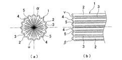
図1は、本発明に係る切削加工方法に用いる切削加工用工具を示したものである。切削加工用工具1は、金属によって略円柱状に形成されており、外周に、16個の突条2,2・・と16個の凹溝3,3・・とが、交互に設けられている。そして、前方から見た場合に、それらの突条2,2・・と凹溝3,3・・とが、中心軸に対する放射方向に交互に位置して連続した波状の凹凸を形成した状態になっている(図1(a)参照)。
[Structure of cutting tool]
FIG. 1 shows a cutting tool used in a cutting method according to the present invention. The
それらの突条2,2・・および凹溝3,3・・によって形成される切削加工用工具1の外周の輪郭線αは、切削加工用工具1の軸中心から突条2の先端までの長さと凹溝の基端(軸中心に一番近い部分)までの長さとの平均値を半径とする円周(図1(a)のu)を想定した場合に、当該輪郭線αの円周uに対する位置(y)が円周u上の任意の位置からの角度(θ)に対してy=A・sin(pθ)(A,pは任意の定数)の関係を満たすように設けられている。また、中心から突条の先端までの長さと中心から凹溝の基端までの長さとの差は、数μm〜数十μmの範囲になるように調整される(図1(a)参照)。
The contour line α of the outer periphery of the
さらに、切削加工用工具1の前端の刃先面には、16個の凸部4,4・・と16個の凹部5,5・・とが、中心軸に対する放射方向に、交互に設けられている。そして、側方から見た場合に、それらの凸部4,4・・と16個の凹部5,5・・とが、波状の凹凸を形成した状態になっている(図1(b)参照)。
Furthermore, 16
それらの凸部4,4・・および凹部5,5・・によって形成される切削加工用工具1の外周の輪郭線βは、凸部4,4・・の先端と凹部5,5・・の基端との中間の位置での外周円(図1(b)のv)を想定した場合に、当該輪郭線βの外周円vに対する長手方向における位置(y)が外周円v上の任意の位置からの角度(θ)に対してy=B・sin(qθ)(A,qは任意の定数)の関係を満たすように設けられている。また、凸部4の先端から凹部5の基端までの長さは、数μm〜数十μmの範囲になるように調整される(図1(b)参照)。
The contour line β of the outer periphery of the
[切削加工用工具を用いた切削加工方法]
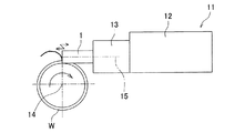
図2は、上記切削加工用工具1を用いて、円柱状の被削材(ワーク)に切削加工を施す様子を示したものである。切削加工用の機械である旋盤11には、図示しないワーク装着手段が設けられており、当該ワーク装着手段を利用して、被削材W(たとえば、円柱状のもの)を、主軸14を中心として回転可能に装着することができるようになっている。また、旋盤11の刃物台12の先端には、工具保持部13が設けられており、当該工具保持部13には、切削加工用工具1を、工具主軸15(ここでは、主軸と直交する軸)を中心として回転可能に装着することができるようになっている。
[Cutting method using cutting tool]
FIG. 2 shows a state in which cutting work is performed on a cylindrical workpiece (work) using the
かかる旋盤11を用いて、被削材Wに切削加工を施す場合には、ワーク装着手段に装着された被削材Wを主軸14を中心として回転させた状態で、工具主軸15を中心として回転させた切削加工用工具1をアプローチさせて(工具主軸15の方向に沿って、あるいは、その他の方向からアプローチさせて)被削材Wに接触させる。そのように切削加工用工具1を被削材Wに接触させる際には、切削加工用工具1の刃先面に形成された連続した波状の凹凸(凸部4,4・・および凹部5,5・・)によって、切削加工用工具1自体および被削材Wに、主分力方向(切削方向に沿った方向)の振動を与えることができる。また、切削加工用工具1の刃先の外周にも連続した波状の凹凸(突条2,2・・および凹溝3,3・・)が形成されているため、切削加工中に、切削加工用工具1自体および被削材Wに、送り分力方向(切削方向と直交した方向)の振動をも与えることができる。たとえば、図1のような工具を用いて工具保持部13を毎分6,000回転の回転数で回転させた場合には、切削加工用工具1および被削材Wに、6,000/60(すなわち、1秒間の回転数)*16(切削加工用工具1の刃先面あるいは刃先の外周の凹凸の数)=1.6kHzの主分力方向および送り分力方向の振動を与えることができる。
When cutting the workpiece W using such a
[切削加工用工具を用いた切削加工による効果]
上記した切削加工方法は、切削加工用工具1の刃先面および工具の刃先の外周に連続した波状の凹凸が形成されているため、切削加工用工具1を用いるだけの容易かつ安価な構成によって、切削加工中に切削加工用工具1自体および被削材Wに主分力方向(切削方向に沿った方向)および送り分力方向(切削方向と直交する方向)の連続した振動を与えることができる。したがって、上記した切削加工方法によれば、切削加工用工具1の刃先と被削材Wとの間の摩擦力を効果的に低減させることができるため、切削屑の長さや厚さを減少させることができる上、加工時の発熱や抵抗の増大を抑えて加工精度を向上させることができる。
[Effects of cutting using cutting tools]
In the cutting method described above, continuous wavy irregularities are formed on the cutting edge surface of the
また、上記した切削加工方法は、切削加工用工具1の刃先面の凹凸(凸部4,4・・および凹部5,5・・)および刃先の外周の凹凸(突条2,2・・および凹溝3,3・・)が、いずれも正弦波状のものであるため、切削加工用工具1の刃先と被削材Wとの間の摩擦力をきわめて効果的に低減させることが可能である。
Further, the cutting method described above includes the unevenness (
[切削加工方法、および工具の変更例]
本発明に係る切削加工方法は、上記実施形態の態様に何ら限定されるものではなく、切削加工機の種類、切削加工用工具の形状等の構成を、本発明の趣旨を逸脱しない範囲内で、必要に応じて適宜変更することができる。
[Changing method and tool change example]
The cutting method according to the present invention is not limited to the aspect of the above embodiment, and the configuration of the type of the cutting machine, the shape of the cutting tool, and the like is within the scope not departing from the gist of the present invention. These can be changed as necessary.
たとえば、切削加工用工具は、上記実施形態の如く、刃先面と刃先の外周との両方に連続した波状の凹凸を設けたものに限定されず、刃先面あるいは刃先の外周のいずれかに連続した波状の凹凸を設けたものに変更することも可能である。なお、上記実施形態の如く、工具の刃先面と刃先の外周との両方に連続した波状の同数の凹凸を設けた場合には、切削加工中に、主分力方向および送り分力方向に同じ振動数の振動を同時に付与することができる、というメリットがある。加えて、刃先面に設ける連続した波状の凹凸の個数や、刃先の外周に設ける連続した波状の凹凸の個数は、上記実施形態の如き16個に限定されず、それぞれ、必要に応じて適宜増減させることができる。また、切削加工機は、上記実施形態の如く、主軸(被削材を支持可能な回転軸)と工具主軸とが直交したものに限定されず、主軸と工具主軸とが直角以外の所定の角度を成すように構成されたものに変更することも可能である。 For example, the cutting tool is not limited to those provided with wavy irregularities on both the cutting edge surface and the outer periphery of the cutting edge as in the above-described embodiment, and is continuous on either the cutting edge surface or the outer periphery of the cutting edge. It is also possible to change to those provided with wavy irregularities. When the same number of continuous wavy irregularities are provided on both the cutting edge surface of the tool and the outer periphery of the cutting edge as in the above embodiment, the same in the main component force direction and the feed component force direction during cutting. There is a merit that vibrations having a frequency can be simultaneously applied. In addition, the number of continuous wavy irregularities provided on the blade edge surface and the number of continuous wavy irregularities provided on the outer periphery of the blade edge are not limited to 16 as in the above embodiment, and each may be increased or decreased as necessary. Can be made. Further, the cutting machine is not limited to the one in which the main shaft (rotary shaft capable of supporting the work material) and the tool main shaft are orthogonal to each other as in the above-described embodiment, and the main shaft and the tool main shaft have a predetermined angle other than a right angle. It is also possible to change to the one configured to form.
本発明の切削加工方法および切削加工用工具は、上記の如く優れた効果を奏するものであるから、各種の切削加工機を利用して被削材を切削加工する際に好適に用いることができる。 Since the cutting method and the cutting tool of the present invention have excellent effects as described above, they can be suitably used when cutting a work material using various cutting machines. .
1・・切削加工用工具
11・・旋盤
12・・刃物台
14・・主軸
15・・工具主軸
W・・被削材
1 ・ ・ Tool for cutting 11 ・ ・
Claims (3)
前記工具が円柱状のものであり、刃先面あるいは刃先の外周に、連続した波状の凹凸が形成されていることを特徴とする切削加工方法。 A cutting method for cutting a work material by causing a tool rotated about a tool main spindle to approach a work material rotated about a main spindle,
A cutting method characterized in that the tool is cylindrical, and continuous wavy irregularities are formed on the cutting edge surface or the outer periphery of the cutting edge.
円柱状に形成されており、刃先面あるいは刃先の外周に、連続した波状の凹凸が形成されていることを特徴とする切削加工用工具。 A tool used when cutting a work material by causing a tool rotated about the tool spindle to approach the work material rotated about the main spindle,
A cutting tool characterized in that it is formed in a cylindrical shape, and continuous wavy irregularities are formed on the cutting edge surface or the outer periphery of the cutting edge.
Priority Applications (1)
| Application Number | Priority Date | Filing Date | Title |
|---|---|---|---|
| JP2010168384A JP2012024907A (en) | 2010-07-27 | 2010-07-27 | Cutting method and cutting tool |
Applications Claiming Priority (1)
| Application Number | Priority Date | Filing Date | Title |
|---|---|---|---|
| JP2010168384A JP2012024907A (en) | 2010-07-27 | 2010-07-27 | Cutting method and cutting tool |
Publications (1)
| Publication Number | Publication Date |
|---|---|
| JP2012024907A true JP2012024907A (en) | 2012-02-09 |
Family
ID=45778470
Family Applications (1)
| Application Number | Title | Priority Date | Filing Date |
|---|---|---|---|
| JP2010168384A Pending JP2012024907A (en) | 2010-07-27 | 2010-07-27 | Cutting method and cutting tool |
Country Status (1)
| Country | Link |
|---|---|
| JP (1) | JP2012024907A (en) |
Cited By (1)
| Publication number | Priority date | Publication date | Assignee | Title |
|---|---|---|---|---|
| JP2014240119A (en) * | 2013-05-13 | 2014-12-25 | 株式会社ジェイテクト | Cutter and cutting method |
-
2010
- 2010-07-27 JP JP2010168384A patent/JP2012024907A/en active Pending
Cited By (1)
| Publication number | Priority date | Publication date | Assignee | Title |
|---|---|---|---|---|
| JP2014240119A (en) * | 2013-05-13 | 2014-12-25 | 株式会社ジェイテクト | Cutter and cutting method |
Similar Documents
| Publication | Publication Date | Title |
|---|---|---|
| KR102012913B1 (en) | Beveling method | |
| JP5555691B2 (en) | drill | |
| JP2018134729A (en) | Internal cylinder engine cylinder wall processing apparatus | |
| KR20070020282A (en) | Method and apparatus for machining rotationally symmetrical surfaces of workpieces | |
| JP5946984B1 (en) | Groove processing method | |
| JP4658667B2 (en) | Manufacturing method of annular optical element and manufacturing method of mold for annular optical element | |
| JP2015525141A (en) | Chamfering cutter with helical pointed blade and discharge groove | |
| WO2013146525A1 (en) | Machine tool | |
| JP6379623B2 (en) | Cutting apparatus and cutting method | |
| JP2012024907A (en) | Cutting method and cutting tool | |
| JP6791957B2 (en) | Chamfering tool with guides to eliminate vibration | |
| JP6723623B1 (en) | Cutting method | |
| JP5534509B2 (en) | Cutting method | |
| JP6996398B2 (en) | Deburring device | |
| WO2010079374A1 (en) | Milling tool for simultaneous roughing and finishing operations | |
| JP6248748B2 (en) | Roughing end mill | |
| RU2604742C2 (en) | Cutting multi-facet plate | |
| JP2018028317A (en) | Piston formation method | |
| JP5895654B2 (en) | End mill | |
| JP2016155178A (en) | Rotary tool and manufacturing method thereof | |
| JP2003117709A (en) | Machine Tools | |
| JP3172438U (en) | Milling tools | |
| JP2013000810A (en) | Curve cutting circular saw | |
| JP2016093860A (en) | Cutting equipment | |
| JP2011212778A (en) | Cutting tool and method for cutting using same |