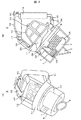
図1に、本実施例の掃除機本体の横断面図を示す。図8に、集塵装置2を取り外した状態で掃除機本体1を切断したときの本発明の実施例の掃除機本体の平面断面図を示す。電気掃除機の使用状態では、掃除機本体1が横置きとなり、電気掃除機の収納状態では、掃除機本体1が縦置きとなるのが好ましい。電気掃除機の使用状態において、本体吸気口21側を前方(上流側)、本体排気口30側を後方(下流側)とすると、電気掃除機の収納状態では、本体吸気口21が重力作用方向上側となり本体排気口30が重力作用方向下側となる。掃除機本体1が横置きされた場合は、掃除機本体1の下面が、掃除機本体1が置かれた面(例えば、床面)に対して平行になり、重力作用方向に対して垂直となる。また、本実施例では、図1に示すように掃除機本体1を横置きした場合、本体吸気口21のある方を掃除機本体1の前方向、本体排気口30のある方を掃除機本体1の後ろ方向とし、掃除機本体1の前方向と後ろ方向にかけて掃除機本体1の縦方向と呼ぶ。また、本実施例では、図1に示すように掃除機本体1を横置きした場合、把手16のある方を掃除機本体1の上方向、基板49のある方を掃除機本体1の下方向とし、掃除機本体1の上方向から下方向にかけて掃除機本体1の高さ方向と呼ぶ。また、本実施例では、図8に示すように、掃除機本体1の両側にある車輪軸(図示せず)の方向を幅方向と呼ぶ。
In FIG. 1, the cross-sectional view of the cleaner body of a present Example is shown. FIG. 8 is a plan sectional view of the cleaner body of the embodiment of the present invention when the cleaner body 1 is cut with the dust collector 2 removed. It is preferable that the vacuum cleaner main body 1 is horizontally placed in the usage state of the vacuum cleaner, and the vacuum cleaner main body 1 is vertically placed in the housed state of the vacuum cleaner. When the vacuum cleaner is in use, if the main body inlet 21 side is the front (upstream side) and the main body exhaust port 30 side is the rear (downstream side), the main body inlet 21 is in the direction of gravity in the housed state of the vacuum cleaner. The main body exhaust port 30 is on the lower side in the direction of gravity action. When the cleaner body 1 is placed horizontally, the lower surface of the cleaner body 1 is parallel to the surface (for example, the floor surface) on which the cleaner body 1 is placed and is perpendicular to the direction of gravity action. Become. Further, in this embodiment, when the vacuum cleaner main body 1 is placed horizontally as shown in FIG. 1, the direction having the main body inlet 21 is the front direction of the cleaner main body 1, and the direction having the main body exhaust port 30 is the main body of the cleaner. 1 is referred to as the longitudinal direction of the cleaner body 1 from the front direction to the rear direction of the cleaner body 1. Further, in this embodiment, when the cleaner body 1 is placed horizontally as shown in FIG. 1, the direction with the handle 16 is upward of the cleaner body 1, and the direction with the substrate 49 is downward of the cleaner body 1. And the height direction of the cleaner body 1 from the upper direction to the lower direction of the cleaner body 1. In this embodiment, as shown in FIG. 8, the direction of the wheel shafts (not shown) on both sides of the cleaner body 1 is referred to as the width direction.
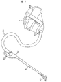
まず、掃除機本体1の構造を説明する。吸い込んだ空気から塵埃を捕集する集塵装置2は、掃除機本体1の前側に着脱自在に配置される。集塵装置2の長手方向(軸方向)を重力作用方向(縦型配置)とすると、掃除機本体1の高さが高くなる。一方、集塵装置2内の旋回流の軸方向(集塵装置2の軸方向)が重力作用方向に近いほど遠心分離作用による分離効果が大きくなり、集塵装置2内の旋回流の軸方向が重力作用方向に対して45度を超えると遠心分離作用による分離効果が極端に低下する。そこで、掃除機本体1の高さを小さくすると共に遠心分離作用による分離効果の低下を抑制するために、本実施例では、集塵装置2の軸方向は、重力作用方向に対して40度〜45度程度とする。ただし、遠心分離作用による分離効果を高くするには、集塵装置2の軸方向は、重力作用方向に対して40度よりも小さくてもよい(例えば、0度)。塵埃分離部(旋回部)4を下側に配置し、塵埃収容部5を上側に配置する代わりに、塵埃分離部4を上側に配置し、塵埃収容部5を下側に配置してもよい。この場合は、入口管3は、塵埃分離部4の軸方向の前側端部の円周面に接続されるのが好ましい。
First, the structure of the cleaner body 1 will be described. The dust collector 2 that collects dust from the sucked air is detachably disposed on the front side of the cleaner body 1. When the longitudinal direction (axial direction) of the dust collector 2 is the gravity action direction (vertical arrangement), the height of the cleaner body 1 is increased. On the other hand, the closer the axial direction of the swirling flow in the dust collector 2 (the axial direction of the dust collecting device 2) is to the gravity acting direction, the greater the separation effect due to the centrifugal separation action, and the axial direction of the swirling flow in the dust collecting device 2 When the angle exceeds 45 degrees with respect to the direction of gravity action, the separation effect due to the centrifugal action is extremely reduced. Therefore, in order to reduce the height of the vacuum cleaner main body 1 and suppress a decrease in the separation effect due to the centrifugal separation action, in this embodiment, the axial direction of the dust collector 2 is 40 degrees to the gravity action direction. It is about 45 degrees. However, in order to increase the separation effect by the centrifugal separation action, the axial direction of the dust collector 2 may be smaller than 40 degrees (for example, 0 degree) with respect to the gravity action direction. Instead of disposing the dust separation unit (swivel unit) 4 on the lower side and the dust storage unit 5 on the upper side, the dust separation unit 4 may be disposed on the upper side and the dust storage unit 5 on the lower side. . In this case, the inlet pipe 3 is preferably connected to the circumferential surface of the front end portion in the axial direction of the dust separator 4.
集塵装置2は、吸い込んだ空気を旋回させ、遠心分離作用(サイクロン方式)によって塵埃を分離する塵埃分離部4と、塵埃分離部4に連通し、塵埃分離部4で分離された塵埃を収容する塵埃収容部5とを備える。塵埃分離部4と塵埃収容部5とは、集塵装置2の軸方向に配列され、それぞれの軸方向端部で接続され、連通する。つまり、塵埃分離部4は、掃除機本体1の前側に配置され、塵埃収容部5は、塵埃分離部4に対して掃除機本体1の後側に配置される。使用者が塵埃分離部4と塵埃収容部5とを容易に分離可能なように、塵埃分離部4と塵埃収容部5とが連結されている。掃除機本体1の前端に、管状の本体吸気口21を備える。塵埃分離部4の軸方向の前側端面の一部は、開口しており、その開口部が入口管3に接続される。塵埃分離部4の軸方向の前側端面ではなく、塵埃分離部4の軸方向の前側端部の円周面が、入口管3に接続されてもよい。入口管3は、掃除機本体1の幅方向の中央に形成されるのが好ましい。内筒7および凹み部8も、掃除機本体1の幅方向の中央に形成されるのが好ましい。
The dust collector 2 swirls the sucked air and communicates with the dust separator 4 that separates the dust by a centrifugal separation action (cyclone method), and the dust separator 4 accommodates the dust separated by the dust separator 4. And a dust storage portion 5 to be provided. The dust separator 4 and the dust container 5 are arranged in the axial direction of the dust collector 2 and are connected and communicated with each other in the axial direction. That is, the dust separator 4 is disposed on the front side of the cleaner body 1, and the dust container 5 is disposed on the rear side of the cleaner body 1 with respect to the dust separator 4. The dust separator 4 and the dust container 5 are connected so that the user can easily separate the dust separator 4 and the dust container 5. A tubular main body inlet 21 is provided at the front end of the cleaner body 1. A part of the front end face in the axial direction of the dust separator 4 is open, and the opening is connected to the inlet pipe 3. Instead of the front end surface in the axial direction of the dust separator 4, the circumferential surface of the front end in the axial direction of the dust separator 4 may be connected to the inlet pipe 3. The inlet pipe 3 is preferably formed at the center in the width direction of the cleaner body 1. The inner cylinder 7 and the recessed portion 8 are also preferably formed at the center in the width direction of the cleaner body 1.
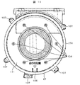
塵埃分離部4は、中空の略円筒状の外筒6と、外筒6と同心軸で外筒6に内包される中空の略円筒状の内筒7を備える。旋回流の軸心が重力によって重力作用方向にずれることによって遠心分離作用による分離効果が低下するのを抑制するために、塵埃分離部4の軸方向が重力作用方向に対して傾いている場合には、内筒7の軸心を外筒6の軸心に対して下方向にずらしてもよい。図3(A)に示すように、外筒6の軸方向一端面(前側端面)は、入口管3に接続される開口を除き閉塞されており、外筒6の軸方向他端面(後側端面)は、開口している。外筒6は、使用者から塵埃の堆積が見えるようにまたは外筒6外に設けたセンサが塵埃の堆積を検出できるように、透明または半透明のプラスチックや樹脂で構成されるのが好ましい。内筒7の軸方向一端面(前側端面)は閉塞されており、内筒7の軸方向他端面(後側端面)は、開口している。図3(A)に示すように、内筒7の軸方向一端面の閉塞部分の中央に、内筒7の軸方向内側へ凹んだ凹み部8が形成される。入口管3は、内筒7の軸方向一端面の閉塞部分、つまり凹み部8に対向している。図3(A)に示すように、凹み部8の一部は、内筒7の外周端まで達している。空気の圧力損失を低減するために、凹み部8の開口方向は、下方向であるのが好ましい。ただし、凹み部8の開口方向は、上方向でも横方向でもよい。図3(A)に示すように、凹み部8の内筒7の外周端部では、凹み部8が内筒7の半径方向に真っ直ぐに向くのではなく、やや円周方向に傾いている。図1に示すように、凹み部8の軸方向の深さは、内筒7の円筒部分の軸方向の長さの略半分程度である。ただし、凹み部8の軸方向の深さは、内筒7の円筒部分の軸方向のほぼ全長にわたってもよい。この場合は、内筒7の円筒部分のほぼ全長にわたって内筒7の円周面の一部に凹み部8の開口が形成されることになる。さらに、凹み部8の外周端部に、案内管38が接続される。案内管38の断面は略1/4円形状であり、内筒7の外周面に沿って形成され、内筒7の外周面も流路の内壁面の一部を形成する。案内管38は、内筒7の外周面に円周方向に数cm程度形成される。よって、入口管3によって軸方向に流入した空気は、凹み部8によって半径方向に向きを変え、さらに、凹み部8の内筒7の外周端部でやや円周方向に変えられ、さらに案内管38で円周方向に変えられる。また、凹み部8は凹凸がなく、曲面で形成されるのが好ましい。これによって、圧力損失を抑制しつつ空気を十分に旋回させることができる。案内管38は、なくても構わない。内筒7の軸方向他端面(後側端面)の外周に、外筒6へ向かって延びる外延部34が形成される。つまり、図3(A)に示すように、内筒7の軸方向他端面(後側端面)は、内筒7の内側が開口した円環状となっている。
The dust separation unit 4 includes a hollow substantially cylindrical outer cylinder 6 and a hollow substantially cylindrical inner cylinder 7 enclosed in the outer cylinder 6 with a concentric axis with the outer cylinder 6. When the axial direction of the dust separation part 4 is inclined with respect to the gravity action direction in order to prevent the separation effect due to the centrifugal separation action from deteriorating due to the axial center of the swirling flow being shifted in the gravity action direction by gravity. The axis of the inner cylinder 7 may be shifted downward with respect to the axis of the outer cylinder 6. As shown in FIG. 3 (A), one axial end surface (front end surface) of the outer cylinder 6 is closed except for an opening connected to the inlet pipe 3, and the other axial end surface (rear side) of the outer cylinder 6 is closed. The end face is open. The outer cylinder 6 is preferably made of transparent or translucent plastic or resin so that dust accumulation can be seen by the user or a sensor provided outside the outer cylinder 6 can detect the accumulation of dust. One end face (front end face) in the axial direction of the inner cylinder 7 is closed, and the other end face (rear end face) in the axial direction of the inner cylinder 7 is open. As shown in FIG. 3A, a recessed portion 8 that is recessed inward in the axial direction of the inner cylinder 7 is formed at the center of the closed portion of one end surface in the axial direction of the inner cylinder 7. The inlet pipe 3 is opposed to the closed portion of one end surface in the axial direction of the inner cylinder 7, that is, the recessed portion 8. As shown in FIG. 3A, a part of the recessed portion 8 reaches the outer peripheral end of the inner cylinder 7. In order to reduce the pressure loss of air, it is preferable that the opening direction of the recessed part 8 is a downward direction. However, the opening direction of the recessed part 8 may be upward or lateral. As shown in FIG. 3A, at the outer peripheral end of the inner cylinder 7 of the recess 8, the recess 8 does not face straight in the radial direction of the inner cylinder 7 but is slightly inclined in the circumferential direction. As shown in FIG. 1, the depth of the recess 8 in the axial direction is about half of the axial length of the cylindrical portion of the inner cylinder 7. However, the axial depth of the recessed portion 8 may extend over substantially the entire axial length of the cylindrical portion of the inner cylinder 7. In this case, the opening of the recessed portion 8 is formed in a part of the circumferential surface of the inner cylinder 7 over almost the entire length of the cylindrical portion of the inner cylinder 7. Further, a guide tube 38 is connected to the outer peripheral end of the recess 8. The cross section of the guide tube 38 has a substantially quarter circle shape, is formed along the outer peripheral surface of the inner cylinder 7, and the outer peripheral surface of the inner cylinder 7 also forms part of the inner wall surface of the flow path. The guide tube 38 is formed on the outer peripheral surface of the inner cylinder 7 in the circumferential direction by about several centimeters. Therefore, the air that has flowed in the axial direction by the inlet pipe 3 is changed in the radial direction by the recessed portion 8 and further changed in the circumferential direction by the outer peripheral end portion of the inner cylinder 7 of the recessed portion 8. At 38, it can be changed in the circumferential direction. Moreover, it is preferable that the recessed part 8 does not have an unevenness | corrugation and is formed in a curved surface. Thereby, air can be sufficiently swirled while suppressing pressure loss. The guide tube 38 may not be provided. An outer extension 34 extending toward the outer cylinder 6 is formed on the outer periphery of the other axial end surface (rear end face) of the inner cylinder 7. That is, as shown in FIG. 3A, the other axial end surface (rear side end surface) of the inner cylinder 7 has an annular shape with the inner side of the inner cylinder 7 opened.
図3(A)に示すように、外延部34の円周方向の一部は、開口している。この開口によって、内筒7外の空気が、塵埃収容部5に流入することができる。内筒7は、菌の繁殖を抑制できるように、抗菌作用のある金属(例えば、銀,銅)や抗菌物質(例えば、銀,銅)を含有するあるいは塗布された金属(例えば、ステンレス)で構成されるのが好ましい。ただし、内筒7は、円筒部分も含め樹脂で構成されてもよい。そして、図3(A)に示すように、外筒6の軸方向他端面から内筒7が軸方向へ挿入されることによって、外延部34の外周端が外筒6の内周に当接され、その結果、外筒6の軸方向他端面が閉塞される。使用者が外筒6と内筒7とを容易に分離可能なように、外筒6と内筒7とが連結される。内筒7の円周面に、複数の貫通孔33を備える。複数の貫通孔33によって、内筒7はフィルタ機能を有する。この貫通孔33によって、大きなごみが内筒7内へ流入することなく、内筒7外側から内筒7内側へ空気が流入することができる。吸込力にもよるが、1円玉以上の重さのごみは、外筒6内を吸い上げられることができず、外筒6内に残ることがある。使用者が外筒6と内筒7とを容易に分離可能なように、外筒6と内筒7とが連結することによって、使用者は、外筒6と内筒7とを容易に分離でき、外筒6内に堆積したごみを容易に排出でき、また、内筒7の貫通孔33に引っかかった髪の毛や糸くずを容易に除去することができる。
As shown in FIG. 3A, a part of the outer extending portion 34 in the circumferential direction is open. With this opening, air outside the inner cylinder 7 can flow into the dust container 5. The inner cylinder 7 is made of an antibacterial metal (for example, silver, copper) or an antibacterial substance (for example, silver, copper) or a coated metal (for example, stainless steel) so as to suppress the growth of bacteria. Preferably it is configured. However, the inner cylinder 7 may be comprised with resin also including a cylindrical part. Then, as shown in FIG. 3A, the outer cylinder 34 is inserted in the axial direction from the other axial end surface of the outer cylinder 6, so that the outer peripheral end of the outer extension 34 comes into contact with the inner periphery of the outer cylinder 6. As a result, the other axial end surface of the outer cylinder 6 is closed. The outer cylinder 6 and the inner cylinder 7 are connected so that the user can easily separate the outer cylinder 6 and the inner cylinder 7. A plurality of through holes 33 are provided on the circumferential surface of the inner cylinder 7. The inner cylinder 7 has a filter function by the plurality of through holes 33. The through-hole 33 allows air to flow from the outer side of the inner cylinder 7 to the inner side of the inner cylinder 7 without large dust flowing into the inner cylinder 7. Although it depends on the suction force, garbage having a weight of 1 yen or more cannot be sucked up in the outer cylinder 6 and may remain in the outer cylinder 6. By connecting the outer cylinder 6 and the inner cylinder 7 so that the user can easily separate the outer cylinder 6 and the inner cylinder 7, the user can easily separate the outer cylinder 6 and the inner cylinder 7 from each other. The dust accumulated in the outer cylinder 6 can be easily discharged, and the hair and lint caught in the through hole 33 of the inner cylinder 7 can be easily removed.
塵埃分離部4と塵埃収容部5との接続部の気密を保つために、内筒7の軸方向他端面に、パッキング9を備える。パッキング9は、外延部34に設けられるだけでなく、内筒7の軸方向にも突出している。よって、内筒7の内側は、完全な中空ではなく、パッキング9によって一部閉塞空間が存在する。さらに、パッキング9の内筒7の内側へ突出した部分に、内筒7の軸方向内側へ凹んだ凹み部39が形成される。凹み部39は把手の機能を有する。これにより、使用者が凹み部39に指を挿入して、塵埃分離部4あるいは内筒7を保持することができる。外延部34の上側の一部は、開口しており、前蓋11の外側流路35に連通する。つまり、外筒6の内側であって内筒7の円筒部分の外側が、前蓋11の外側流路35に連通する。図3(A)に示すように、外延部34の上側の一部の開口の円周方向の壁面は、円周方向に案内管38の開口に対向する側の壁面が高く、円周方向に案内管38の開口側の壁面が低いのが好ましい。例えば、塵埃分離部4を前方から見た場合に案内管38の開口方向が反時計回り方向だとすると、外延部34の上側の一部の開口の円周方向の壁面のうち左側の壁面が高く、右側の壁面が低い。つまり、外延部34の上側の一部が開口しているため、外延部34の円周方向は、内筒7の外周の一周分には満たないが、らせん状にずれている。よって、内筒7外の旋回流は、外延部34の上側の一部の開口の円周方向の高い壁面にぶつかって、スムースに軸方向へ向きを変えることができ、旋回流に含まれる塵埃も塵埃収容部5へ流れやすくなる。一方、内筒7の内側は、前蓋11の内側流路36に連通する。
In order to keep the airtightness of the connecting portion between the dust separator 4 and the dust container 5, a packing 9 is provided on the other axial end surface of the inner cylinder 7. The packing 9 is not only provided on the outer extension 34, but also projects in the axial direction of the inner cylinder 7. Therefore, the inside of the inner cylinder 7 is not completely hollow, and a partially closed space exists due to the packing 9. Further, a recessed portion 39 that is recessed inward in the axial direction of the inner cylinder 7 is formed in a portion of the packing 9 that protrudes to the inner side of the inner cylinder 7. The recess 39 has a handle function. Thereby, the user can hold the dust separation part 4 or the inner cylinder 7 by inserting a finger into the recess 39. A part of the upper side of the extended portion 34 is open and communicates with the outer flow path 35 of the front lid 11. That is, the inside of the outer cylinder 6 and the outside of the cylindrical portion of the inner cylinder 7 communicates with the outer flow path 35 of the front lid 11. As shown in FIG. 3 (A), the circumferential wall surface of the opening on the upper side of the extended portion 34 has a high wall surface on the side facing the opening of the guide tube 38 in the circumferential direction. The wall surface on the opening side of the guide tube 38 is preferably low. For example, assuming that the opening direction of the guide tube 38 is the counterclockwise direction when the dust separation unit 4 is viewed from the front, the left wall surface is high among the circumferential wall surfaces of a part of the upper opening of the extension portion 34, The wall on the right side is low. That is, since a part of the upper side of the extended portion 34 is opened, the circumferential direction of the extended portion 34 is less than one round of the outer periphery of the inner cylinder 7 but is shifted in a spiral shape. Therefore, the swirling flow outside the inner cylinder 7 can hit the circumferentially high wall surface of a part of the opening on the upper side of the extended portion 34 and can smoothly change the direction in the axial direction. Also easily flows to the dust container 5. On the other hand, the inner side of the inner cylinder 7 communicates with the inner flow path 36 of the front lid 11.
塵埃収容部5は、軸方向一端面(前側端面)と軸方向他端面(後側端面)とが開口し、縦断面で略逆三角形状の中空のケース10を備える。ケース10の軸方向一端面は、開閉可能な前蓋11によって閉塞される。前蓋11の下端部に軸31を備え、軸31はケース10の下端部によって支持される。前蓋11は、軸31を支点としてケース10の軸方向に前後回動可能である。前蓋11の上端部のケース10側には、爪が突出している。一方、ケース10の前側上部に、使用者が押下することが可能なボタン17(レバーでもよい)を備え、ボタン17に、ケース10の前側に延びる伝達棒(ロッド)18が連結されている。伝達棒18の一端は、ボタン17に連結され、伝達棒18の他端は、爪状に形成されている。伝達棒18の他端の爪は、前蓋11の上端部の爪に係合可能である。ケース10に前蓋11が閉じられた状態では、伝達棒18の他端の爪と前蓋11の上端部の爪とが係合して、前蓋11が開くのを防止することができる。そして、使用者がボタン17を押下すると伝達棒18が前側へスライドして(上側に回動してもよい)、伝達棒18の他端の爪と前蓋11の上端部の爪との係合が解除され、重力によってケース10から前蓋11を開くことができる。把手16の形成方向が水平であるのに対して、ケース10の軸方向一端面(前蓋11部分に相当)の法線方向は、水平方向に対して45°〜50°傾斜している。つまり、使用者が把手16を握って塵埃収容部5を持ち上げた際には、ケース10の軸方向一端面(前蓋11部分に相当)は、下方向(重力作用方向)を向いている。よって、重力によってケース10から前蓋11が開くことができる。尚、後述するが、集塵かご(集塵容器)12が、バネ(弾性体)によってケース10の前側へ飛び出すように付勢されていれば、集塵かご12が前蓋11の後面を押すため、使用者がボタン17を押下すると、集塵かご12の押す力によってスムースにケース10から前蓋11が開くこともできる。換言すると、集塵かご12の開口面が前蓋11の後面によって押さえられることによって、集塵かご12がケース10内に収納され、その収納状態が維持される。
The dust container 5 is provided with a hollow case 10 having an axially one end surface (front end surface) and an axial other end surface (rear side end surface) that are substantially inverted triangular in longitudinal section. One end surface in the axial direction of the case 10 is closed by a front lid 11 that can be opened and closed. A shaft 31 is provided at the lower end of the front lid 11, and the shaft 31 is supported by the lower end of the case 10. The front lid 11 can be rotated back and forth in the axial direction of the case 10 with the shaft 31 as a fulcrum. A claw projects from the upper end portion of the front lid 11 on the case 10 side. On the other hand, a button 17 (which may be a lever) that can be pressed by the user is provided on the upper front side of the case 10, and a transmission rod (rod) 18 extending to the front side of the case 10 is connected to the button 17. One end of the transmission rod 18 is connected to the button 17, and the other end of the transmission rod 18 is formed in a claw shape. The claw at the other end of the transmission rod 18 can be engaged with the claw at the upper end of the front lid 11. When the front lid 11 is closed to the case 10, it is possible to prevent the front lid 11 from being opened by engaging the claw at the other end of the transmission rod 18 and the claw at the upper end of the front lid 11. When the user presses the button 17, the transmission rod 18 slides forward (may rotate upward), and the engagement between the other end of the transmission rod 18 and the upper end of the front lid 11 is engaged. The combination is released and the front lid 11 can be opened from the case 10 by gravity. While the handle 16 is formed in a horizontal direction, the normal direction of one end surface in the axial direction of the case 10 (corresponding to the front lid 11 portion) is inclined by 45 ° to 50 ° with respect to the horizontal direction. That is, when the user holds the handle 16 and lifts the dust container 5, one end surface in the axial direction of the case 10 (corresponding to the front lid 11 portion) faces downward (the direction of gravity action). Therefore, the front lid 11 can be opened from the case 10 by gravity. As will be described later, if the dust collection basket (dust collection container) 12 is urged by a spring (elastic body) to jump out to the front side of the case 10, the dust collection basket 12 pushes the rear surface of the front lid 11. Therefore, when the user presses the button 17, the front lid 11 can be smoothly opened from the case 10 by the pressing force of the dust collecting basket 12. In other words, when the opening surface of the dust collecting basket 12 is pressed by the rear surface of the front lid 11, the dust collecting basket 12 is stored in the case 10 and the stored state is maintained.
ケース10の軸方向他端面は、開閉可能なフィルタ15によって閉塞される。フィルタ15の下端部に軸32を備え、軸32はケース10の下端部によって支持される。フィルタ15は、軸32を支点としてケース10の軸方向に前後回動可能である。フィルタ15は、断面形状が略四角形の枠体内にプリーツ状に折られたフィルタ部材が形成される。図4(B)に示すように、フィルタ部材の波方向は高さ方向(重力作用方向)であるのが好ましい。フィルタ15は、例えば、高密度のHEPAフィルタ(High Efficiency Particulate Air Filter)である。HEPAフィルタとは、定格風量で粒径が0.3μmの粒子に対して99.97%以上の粒子捕集率をもち、かつ初期圧力損失が245Pa以下の性能を持つエアフィルタである。フィルタ15のケース10の反対側の面に、パッキング25を備えていてもよい。パッキング25によって、塵埃収容部5の軸方向他端面と掃除機本体1(特に吸気ダクト27入口)との気密を保持できる。尚、軸31と軸32は、共用されてもよい。また、軸32は、フィルタ15の下端部ではなく、フィルタ15の上端部に備えられてもよい。
The other axial end surface of the case 10 is closed by a filter 15 that can be opened and closed. A shaft 32 is provided at the lower end of the filter 15, and the shaft 32 is supported by the lower end of the case 10. The filter 15 can be rotated back and forth in the axial direction of the case 10 with the shaft 32 as a fulcrum. The filter 15 is formed with a filter member folded in a pleat shape within a frame body having a substantially square cross-sectional shape. As shown in FIG. 4B, the wave direction of the filter member is preferably the height direction (gravity acting direction). The filter 15 is, for example, a high-density HEPA filter (High Efficiency Particulate Air Filter). A HEPA filter is an air filter having a particle collection rate of 99.97% or more with respect to particles having a rated air volume of 0.3 μm and an initial pressure loss of 245 Pa or less. A packing 25 may be provided on the surface of the filter 15 opposite to the case 10. By the packing 25, the airtightness between the other axial end surface of the dust container 5 and the cleaner body 1 (particularly, the inlet of the intake duct 27) can be maintained. The shaft 31 and the shaft 32 may be shared. Further, the shaft 32 may be provided not at the lower end portion of the filter 15 but at the upper end portion of the filter 15.
ケース10に、集塵かご12を内包する。集塵かご12の形状は、一つの面が開口したかご形状,立体的形状,箱形状または容器形状であってもよいし、ちりとり形状であってもよい。つまり、集塵かご12は、開口と反対側に凹んだ形状を有する。集塵かご12の断面形状は、略四角形状であってもよいし、略円形状であってもよいし、略三角形状であってもよい。集塵かご12の断面形状は、開口面から底面へ向かって、小さくなるのが好ましい。これによって、塵埃が排出される側(開口側)に向かって断面積が拡がるため、使用者は、集塵かご12内に堆積した塵埃を容易に排出することができる。集塵かご12の形状は、枠体(支骨)によって形成される。集塵かご12の開口面以外の底面、上下左右面に、金属やナイロンなどで構成されたメッシュ部材が被覆または貼着されているのが好ましい。集塵かご12の底面だけでなく、上下左右面にも通気性を持たせることによって、集塵かご12の底面に塵埃が堆積しても流路を確保することができ、吸い込み空気の圧力損失を低減し、吸引力の低下を抑制することができる。このメッシュ部材は、通気性があり、塵埃を捕集するフィルタ機能を有する。通気性があり、塵埃を捕集するフィルタ機能を有するものであれば、メッシュ部材の代わりに使い捨てのティッシュペーパでもよいし、メッシュ部材とティッシュペーパとを組み合わせてもよい。例えば、メッシュ部材の上に使用者がティッシュペーパを装着してもよい。集塵かご12の開口面は、ケース10の軸方向一端面(前側端面)の開口面に一致する。つまり、集塵かご12の開口方向と、ケース10の軸方向一端面の開口方向とが同一である。そして、図6に示すように、集塵かご12の開口面の外周端の上側半分程度は、ケース10の軸方向一端面の内周面に当接し、集塵かご12の開口面の外周端の下側半分程度は、ケース10の軸方向一端面の内周面に当接していない。集塵かご12に下部に軸14を備える。軸14は、ケース10内に支持される。よって、集塵かご12は下部の軸14を支点として、ケース10の軸方向前後に回動可能である。これによって、塵埃収容部5から前蓋11が開かれた際に、重力によって塵埃収容部5から集塵かご12の一部が飛び出すことができる。ケース10に対する軸14の形成位置は、ケース10に対する軸31の形成位置と同じ側(下側)であるため、塵埃収容部5から前蓋11が開かれた際に、前蓋11によって阻害されることなく、塵埃収容部5から集塵かご12の一部が飛び出すことができる。さらに、軸14に集塵かご12を前蓋11側に押し出す方向に弾性力が作用するつるまきバネを備えてもよい。これによって、塵埃収容部5から前蓋11が開かれた際に、バネの弾性力によって塵埃収容部5から集塵かご12の一部が勢いよく飛び出すことができ、使用者は、集塵かご12内に堆積した塵埃を容易に排出することができる。さらに、集塵かご12は、上下に2分割されており、つまり上半分の枠体(支骨)と下半分の枠体(支骨)という2つの構造物からなるのが好ましい。2分割された集塵かご12は、集塵かご12の底面の外側に形成された軸13によって連結される。よって図4(A)に示すように、集塵かご12は、底面の中間を支点として、集塵かご12の開口面が上下に割れる。特に、集塵かご12の一部が塵埃収容部5から飛び出した際に、集塵かご12が上下に割れる。これによって、使用者は、集塵かご12内に堆積した塵埃をさらに容易に排出することができる。特に、集塵かご12の内面にへばりついた塵埃も容易にはがし落とすことができる。ただし、集塵かご12の上下2分割の構成は、必須ではない。また、上述したようにケース10の前側は重力作用方向に対し40°〜45°傾いていることに加え、集塵かご12は塵埃収容部5から30°傾いて飛び出すため、集塵かご12内に堆積した塵埃を略重力方向に排出することができる。
A dust collecting basket 12 is enclosed in the case 10. The shape of the dust collecting basket 12 may be a cage shape with one surface opened, a three-dimensional shape, a box shape, a container shape, or a dustpan shape. That is, the dust collecting basket 12 has a shape recessed on the opposite side to the opening. The cross-sectional shape of the dust collecting basket 12 may be a substantially square shape, a substantially circular shape, or a substantially triangular shape. The cross-sectional shape of the dust collecting basket 12 is preferably smaller from the opening surface toward the bottom surface. As a result, the cross-sectional area increases toward the side (opening side) where the dust is discharged, so that the user can easily discharge the dust accumulated in the dust collecting basket 12. The shape of the dust collecting basket 12 is formed by a frame body (support frame). It is preferable that a mesh member made of metal, nylon, or the like is coated or adhered to the bottom surface of the dust collecting basket 12 other than the opening surface, the top, bottom, left and right surfaces. By providing not only the bottom surface of the dust collecting basket 12 but also the top, bottom, left, and right surfaces, air flow can be secured even if dust accumulates on the bottom surface of the dust collecting basket 12, and the pressure loss of the suction air Can be reduced, and a decrease in suction force can be suppressed. This mesh member is air permeable and has a filter function of collecting dust. A disposable tissue paper may be used instead of the mesh member, or a mesh member and a tissue paper may be combined as long as they are breathable and have a filter function for collecting dust. For example, the user may wear tissue paper on the mesh member. The opening surface of the dust collecting basket 12 coincides with the opening surface of one end surface (front end surface) in the axial direction of the case 10. That is, the opening direction of the dust collecting basket 12 and the opening direction of the one end surface in the axial direction of the case 10 are the same. As shown in FIG. 6, the upper half of the outer peripheral end of the opening surface of the dust collecting basket 12 abuts on the inner peripheral surface of one end surface in the axial direction of the case 10, and the outer peripheral end of the opening surface of the dust collecting basket 12. The lower half is not in contact with the inner peripheral surface of one end surface of the case 10 in the axial direction. The dust collecting basket 12 has a shaft 14 at the bottom. The shaft 14 is supported in the case 10. Therefore, the dust collecting basket 12 can be rotated back and forth in the axial direction of the case 10 with the lower shaft 14 as a fulcrum. Thereby, when the front lid 11 is opened from the dust container 5, a part of the dust collecting basket 12 can be ejected from the dust container 5 by gravity. Since the formation position of the shaft 14 with respect to the case 10 is on the same side (lower side) as the formation position of the shaft 31 with respect to the case 10, the front cover 11 is obstructed when the front cover 11 is opened from the dust container 5. A part of the dust collecting basket 12 can be ejected from the dust container 5 without any trouble. Furthermore, you may equip the axis | shaft 14 with the helical spring which an elastic force acts in the direction which pushes out the dust collection basket 12 to the front cover 11 side. As a result, when the front lid 11 is opened from the dust container 5, a part of the dust collection basket 12 can jump out of the dust container 5 vigorously by the elastic force of the spring. The dust accumulated in 12 can be easily discharged. Further, the dust collecting basket 12 is divided into two parts in the vertical direction, that is, it is preferably composed of two structures, that is, an upper half frame (support) and a lower half frame (support). The two divided dust collecting baskets 12 are connected by a shaft 13 formed outside the bottom surface of the dust collecting basket 12. Therefore, as shown in FIG. 4 (A), the dust collecting basket 12 has the opening surface of the dust collecting basket 12 split vertically, with the middle of the bottom as a fulcrum. In particular, when a part of the dust collection basket 12 jumps out of the dust container 5, the dust collection basket 12 breaks up and down. As a result, the user can more easily discharge the dust accumulated in the dust collecting basket 12. In particular, dust stuck to the inner surface of the dust collecting basket 12 can be easily removed. However, the upper and lower divided configuration of the dust collecting basket 12 is not essential. In addition to the fact that the front side of the case 10 is inclined by 40 ° to 45 ° with respect to the direction of gravity as described above, the dust collection basket 12 jumps out of the dust container 5 by 30 °, so that the inside of the dust collection basket 12 The dust accumulated on the surface can be discharged substantially in the direction of gravity.
前蓋11内には、軸方向に貫通する外側流路35および内側流路36が形成される。そして、外側流路35は、前蓋11の上側に形成され、外側流路35の一端は塵埃分離部4の特に外筒6と内筒7の筒部の間にあたる外延部34の開口に連通し、外側流路35の他端はケース10の特に集塵かご12の開口に連通する。電気掃除機の停止時に、集塵かご12に堆積した塵埃が外側流路35および塵埃分離部4に逆流するのを防止するために、外側流路35の他端は集塵かご12の開口のうち半分よりも上側あるいは上端近傍に連通するのが好ましい。ただし、外側流路35の他端は、集塵かご12の開口の中央部に連通してもよい。さらに、電気掃除機の停止時に、集塵かご12に堆積した塵埃が外側流路35および塵埃分離部4に逆流するのを防止するために、外側流路35の内部または他端部に、外側流路35を覆う逆止弁(図示せず)を形成するのが好ましい。逆止弁は、上端を支点として、集塵かご12内へ回動する。ただし、逆止弁は必須の構成ではない。外側流路35の断面積は、外側流路35の一端から他端へ向けて拡大している。外側流路35の形成方向は、外側流路35の一端から他端へ向けて前蓋11の外側から中心側へ向かう方向である。つまり、集塵かご12の外側から中心側へ向かう方向である。外側流路35から集塵かご12へ流入する空気の乱れを抑制するため、外側流路35の形成方向は、集塵かご12の外側流路35が連通する側の壁面(上側壁面)の方向であるのが好ましい。内側流路36は、前蓋11の中央から下側にかけて形成され、内側流路36の一端は塵埃分離部4の特に内筒7の軸方向他端開口(内筒7内)に連通し、内側流路36の他端はケース10の特に集塵かご12の外側に連通する。内側流路36の他端は、集塵かご12の外部下側に連通するのが好ましい。内側流路36は、外側流路35を避けて形成される。内側流路36の断面積は、外側流路35とは逆に、内側流路36の一端から他端へ向けて縮小している。
An outer channel 35 and an inner channel 36 penetrating in the axial direction are formed in the front lid 11. The outer flow path 35 is formed on the upper side of the front lid 11, and one end of the outer flow path 35 communicates with the opening of the extended part 34, particularly between the outer cylinder 6 and the inner cylinder 7 of the dust separation part 4. The other end of the outer flow path 35 communicates with the opening of the dust collecting basket 12 in the case 10. In order to prevent the dust accumulated in the dust collecting basket 12 from flowing back to the outer flow path 35 and the dust separation part 4 when the vacuum cleaner is stopped, the other end of the outer flow path 35 is the opening of the dust collecting basket 12. Of these, it is preferable to communicate with the upper half or near the upper end. However, the other end of the outer flow path 35 may communicate with the central portion of the opening of the dust collecting basket 12. Furthermore, in order to prevent the dust accumulated in the dust collecting basket 12 from flowing back to the outer flow path 35 and the dust separator 4 when the vacuum cleaner is stopped, A check valve (not shown) that covers the flow path 35 is preferably formed. The check valve rotates into the dust collecting basket 12 with the upper end as a fulcrum. However, the check valve is not an essential configuration. The cross-sectional area of the outer flow path 35 increases from one end of the outer flow path 35 toward the other end. The formation direction of the outer flow path 35 is a direction from the outer side of the front lid 11 toward the center side from one end of the outer flow path 35 to the other end. That is, the direction is from the outside of the dust collecting basket 12 toward the center side. In order to suppress the turbulence of the air flowing into the dust collecting basket 12 from the outer flow path 35, the outer flow path 35 is formed in the direction of the wall surface (upper wall surface) on the side where the outer flow path 35 of the dust collecting basket 12 communicates. Is preferred. The inner flow path 36 is formed from the center of the front lid 11 to the lower side, and one end of the inner flow path 36 communicates with the other end opening in the axial direction of the inner cylinder 7 (inside the inner cylinder 7) of the dust separator 4; The other end of the inner flow path 36 communicates with the case 10, particularly with the outside of the dust collecting basket 12. The other end of the inner flow path 36 is preferably in communication with the lower outside of the dust collecting basket 12. The inner flow path 36 is formed avoiding the outer flow path 35. Contrary to the outer flow path 35, the cross-sectional area of the inner flow path 36 is reduced from one end of the inner flow path 36 toward the other end.
塵埃収容部5の上部外側には、水平方向に延びる、使用者が握ることが可能な把手16を備える。使用者は、この把手16を持って、塵埃収容部5を上方へ持ち上げ、塵埃分離部4を掃除機本体1に残したまま、塵埃収容部5のみを掃除機本体1から取り外すことができる。尚、塵埃分離部4と塵埃収容部5とを連結していれば、使用者は、この把手16を持って、塵埃収容部5を上方へ持ち上げれば、塵埃分離部4と塵埃収容部5とを一体として、つまり集塵装置2そのものを掃除機本体1から取り外すこともできる。図1に示すように、塵埃収容部5の軸方向他端面(フィルタ15部分に相当)の形成方向は、垂直面(重力作用方向)よりはケース10側に傾斜するのが好ましい。つまり、塵埃収容部5の軸方向他端面の上部よりも下部がケース10側に近いのが好ましい。また、図1に示すように、塵埃収容部5の軸方向一端面(前蓋11部分に相当)の形成方向は、垂直面(重力作用方向)よりはケース10側に40°〜45°程度傾斜している。つまり、塵埃収容部5の軸方向一端面の上部よりも下部がケース10側に近い。これによって、塵埃収容部5の軸方向一端面と軸方向他端面とは、垂直面(重力作用方向)を基準として、逆ハの字形状となる。これによって、使用者が塵埃収容部5を上方へ持ち上げる際に引っかかりが少なくなり、使用者は、塵埃収容部5を掃除機本体1から容易に取り外すことができる。そして、使用者は、塵埃収容部5の取り外し後に、凹み部39を持って、塵埃分離部4を上方または斜め上方へ持ち上げ、塵埃分離部4を掃除機本体1から容易に取り外すことができる。図1に示すように、塵埃分離部4の軸方向一端面(入口管3部分に相当)の形成方向は、垂直面(重力作用方向)よりは外筒6側に傾斜するのが好ましい。つまり、塵埃分離部4の軸方向他端面の上部よりも下部が外筒6側に近いのが好ましい。これによって、使用者が塵埃分離部4を上方または斜め上方へ持ち上げる際に引っかかりが少なくなり、使用者は、塵埃分離部4を掃除機本体1から容易に取り外すことができる。また、使用者が塵埃分離部4を取り外す場合だけでなく、塵埃分離部4と塵埃収容部5とを一体として、つまり集塵装置2そのものを掃除機本体1から取り外す際も、集塵装置2の軸方向一端面と軸方向他端面とは、垂直面(重力作用方向)を基準として、逆ハの字形状となるため、集塵装置2を上方へ持ち上げる際に引っかかりが少なくなり、使用者は、集塵装置2を掃除機本体1から容易に取り外すことができる。
A handle 16 that extends in the horizontal direction and can be gripped by the user is provided on the outer side of the upper portion of the dust container 5. The user can hold the handle 16, lift the dust container 5 upward, and remove only the dust container 5 from the cleaner body 1 while leaving the dust separator 4 in the cleaner body 1. In addition, if the dust separation part 4 and the dust storage part 5 are connected, if the user holds the handle 16 and lifts the dust storage part 5 upward, the dust separation part 4 and the dust storage part 5 will be described. And, that is, the dust collector 2 itself can be removed from the cleaner body 1. As shown in FIG. 1, the axial direction other end surface (corresponding to the filter 15 portion) of the dust container 5 is preferably inclined toward the case 10 than the vertical surface (gravity acting direction). That is, it is preferable that the lower part is closer to the case 10 side than the upper part of the other axial end surface of the dust container 5. Moreover, as shown in FIG. 1, the formation direction of the axial direction one end surface (equivalent to front cover 11 part) of the dust accommodating part 5 is about 40 to 45 degrees on the case 10 side from the vertical surface (gravity acting direction). Inclined. That is, the lower part is closer to the case 10 side than the upper part of the one axial end surface of the dust container 5. As a result, the one end surface in the axial direction and the other end surface in the axial direction of the dust container 5 have an inverted C shape with respect to the vertical surface (gravity acting direction). Thereby, when a user lifts the dust accommodating part 5 upward, it becomes less caught, and the user can easily remove the dust accommodating part 5 from the cleaner body 1. Then, the user can easily remove the dust separator 4 from the cleaner body 1 by holding the recess 39 and lifting the dust separator 4 upward or obliquely upward after removing the dust container 5. As shown in FIG. 1, it is preferable that the axial direction one end surface (corresponding to the inlet pipe 3 portion) of the dust separating portion 4 is inclined toward the outer cylinder 6 rather than the vertical surface (gravity acting direction). That is, it is preferable that the lower part is closer to the outer cylinder 6 side than the upper part of the other axial end surface of the dust separator 4. As a result, when the user lifts the dust separator 4 upward or obliquely upward, there is less catching, and the user can easily remove the dust separator 4 from the cleaner body 1. Further, not only when the user removes the dust separator 4, but also when the dust separator 4 and the dust container 5 are integrated, that is, when the dust collector 2 itself is removed from the cleaner body 1. Since the one end surface in the axial direction and the other end surface in the axial direction have an inverted C shape with respect to the vertical surface (the direction of gravity action), the user is less likely to be caught when lifting the dust collector 2 upward. Can easily remove the dust collector 2 from the cleaner body 1.
本体吸気口21には、ホース継手管20が挿入され、ホース継手管20を保持可能である。本体吸気口21の一端に、パッキング22を備える。これによって、ホース継手管20と入口管3との気密を保持できる。掃除機本体1の前方下端(集塵装置2の下側)に、キャスタを支持するためのキャスタ支持部23を備える。掃除機本体1内の後方上側に、掃除機本体1の前後方向に延びる吸気ダクト27を備える。吸気ダクト27の延設方向一端の開口27aは、フィルタ15に対向する。吸気ダクト27の一端の開口27a付近に、補助フィルタ26を備える。これによって、集塵装置2外に残った塵埃を電動送風機28が吸い込むのを抑制することができる。吸気ダクト27の延設方向他端は閉塞されており、吸気ダクト27の延設方向他端近傍の下部、つまり、電動送風機28側が吸気ダクト27の排出口27bとして開口している。掃除機本体1の吸気ダクト27の一端の開口27aの上部に、フィルタ15に接触する位置に、フィルタ15に付着した塵埃を除去する除塵装置24を備える。除塵装置24は回転体の外周にらせん状のバネ(弾性体)を備える。除塵装置24はモータによってまたはコードリール41の周囲に設けられたコード47の引き出しによって回転して、らせん状のバネがフィルタ15のフィルタ部材を弾くことによって、フィルタ15に付着した塵埃を振るい落とす。上述したように、フィルタ15の波方向は高さ方向のため、振るい落とされた塵埃は重力作用方向に落ちやすくなっている。フィルタ15から振るい落とされた塵埃は、ケース10内に堆積することとなる。これによって、フィルタ15の目詰まりを抑制し、空気の圧力損失の低下を抑制し、吸引力の低下を抑制することができる。
A hose joint pipe 20 is inserted into the main body inlet 21 and can hold the hose joint pipe 20. A packing 22 is provided at one end of the main body inlet 21. Thereby, the airtightness of the hose joint pipe 20 and the inlet pipe 3 can be maintained. A caster support portion 23 for supporting casters is provided at the front lower end of the vacuum cleaner body 1 (below the dust collector 2). An intake duct 27 extending in the front-rear direction of the cleaner body 1 is provided on the upper rear side in the cleaner body 1. An opening 27 a at one end in the extending direction of the intake duct 27 faces the filter 15. An auxiliary filter 26 is provided near the opening 27 a at one end of the intake duct 27. Thereby, it is possible to suppress the electric blower 28 from sucking the dust remaining outside the dust collector 2. The other end in the extending direction of the intake duct 27 is closed, and the lower portion in the vicinity of the other end in the extending direction of the intake duct 27, that is, the electric blower 28 side is opened as a discharge port 27 b of the intake duct 27. A dust removing device 24 that removes dust adhering to the filter 15 is provided at a position in contact with the filter 15 at an upper portion of the opening 27 a at one end of the intake duct 27 of the cleaner body 1. The dust removing device 24 includes a spiral spring (elastic body) on the outer periphery of the rotating body. The dust removing device 24 is rotated by a motor or by pulling out a cord 47 provided around the cord reel 41, and a spiral spring bounces the filter member of the filter 15, so that dust attached to the filter 15 is shaken off. As described above, since the wave direction of the filter 15 is in the height direction, the dust that has been shaken off easily falls in the direction of gravity. The dust shaken off from the filter 15 accumulates in the case 10. Accordingly, clogging of the filter 15 can be suppressed, a decrease in air pressure loss can be suppressed, and a decrease in suction force can be suppressed.
図1に示すように、掃除機本体1内の後方下側に、吸引力を発生する電動送風機28を備える。電動送風機28は、電動送風機28の吸込口28aが上方を向く縦置きで設置される。電動送風機28は、吸込口28aの面からその吸込口28aの面の反対面までが最も長い。そのため、電動送風機28の吸込口28aが上方を向くよう電動送風機28を縦置きで設置することによって、ホース継手管20から本体排気口30までの掃除機本体1の長さを短くすることができる。掃除機本体1内において電動送風機28の上部には吸気ダクト27が設けられており、電動送風機28の吸込口28aと吸気ダクト27の排出口27bとが連結されている。本実施例では、電動送風機28を掃除機本体1内に設置した場合、電動送風機28の上部の上面に吸込口28aを有し、電動送風機28の下部の側部に排気口28bを有するよう設置される。掃除機本体1内において、電動送風機28の下流側かつ電動送風機28よりも前側に、電動送風機28の排気口28bに連通する排気ダクト40を備える。さらに、掃除機本体1内において排気ダクト40の下流側かつ排気ダクト40よりも前側に、排気ダクト40に連通するフィルタ29を備える。排気ダクト40とフィルタ29は、ねじなどの固定手段で固定されている。これは、排気ダクト40とフィルタ29を固定することで排気ダクト40とフィルタ29との気密を保持でき、電動送風機28の排気口28bから出る全ての排気がフィルタ29を通過することができるようにするためである。フィルタ29は、断面形状が略四角形の枠体内にプリーツ状に折られたフィルタ部材が形成される。フィルタ部材の波方向は高さ方向(重力作用方向)であるのが好ましい。フィルタ29は、例えば、高密度のULPAフィルタ(Ultra Low Penetration Air Filter)である。ULPAフィルタは、定格風量で粒径が0.15μmの粒子に対して99.9995%以上の粒子捕集率をもち、かつ初期圧力損失が245Pa以下の性能を持つエアフィルタであり、HEPAフィルタの粒子捕集効率よりも高い粒子捕集効率を有する。そして、掃除機本体1の後端面に、本体排気口30を備える。
As shown in FIG. 1, an electric blower 28 that generates a suction force is provided on the lower rear side in the cleaner body 1. The electric blower 28 is installed in a vertical position with the suction port 28a of the electric blower 28 facing upward. The electric blower 28 is longest from the surface of the suction port 28a to the surface opposite to the surface of the suction port 28a. Therefore, the length of the vacuum cleaner main body 1 from the hose joint pipe 20 to the main body exhaust port 30 can be shortened by installing the electric blower 28 vertically so that the suction port 28a of the electric blower 28 faces upward. . An intake duct 27 is provided in the upper part of the electric blower 28 in the cleaner main body 1, and the suction port 28 a of the electric blower 28 and the discharge port 27 b of the intake duct 27 are connected to each other. In the present embodiment, when the electric blower 28 is installed in the cleaner body 1, the electric blower 28 has an intake port 28 a on the upper surface of the upper part and an exhaust port 28 b on the lower side of the electric blower 28. Is done. In the cleaner body 1, an exhaust duct 40 communicating with the exhaust port 28 b of the electric blower 28 is provided downstream of the electric blower 28 and in front of the electric blower 28. Further, a filter 29 communicating with the exhaust duct 40 is provided in the cleaner body 1 on the downstream side of the exhaust duct 40 and on the front side of the exhaust duct 40. The exhaust duct 40 and the filter 29 are fixed by fixing means such as screws. This is because the exhaust duct 40 and the filter 29 are fixed so that the airtightness between the exhaust duct 40 and the filter 29 can be maintained, and all the exhaust gas emitted from the exhaust port 28b of the electric blower 28 can pass through the filter 29. It is to do. The filter 29 is formed with a filter member folded in a pleat shape in a frame body having a substantially square cross section. The wave direction of the filter member is preferably the height direction (gravity acting direction). The filter 29 is, for example, a high-density ULPA filter (Ultra Low Penetration Air Filter). The ULPA filter is an air filter having a particle collection rate of 99.9995% or more for particles having a rated air volume of 0.15 μm and an initial pressure loss of 245 Pa or less. The particle collection efficiency is higher than the particle collection efficiency. And the main body exhaust port 30 is provided in the rear-end surface of the cleaner body 1. FIG.
図8に示すようにコード47は先端にプラグ43を有している。プラグ43を部屋などにあるコンセントに差し込むことで電気を得る。充電式掃除機以外の電気掃除機の使用時には、プラグ43をコンセントに差し込まないと電動送風機28などを作動させることができない。そのため、電気掃除機の使用時に邪魔にならない箇所にコードリール41を設けることが好ましい。以下、コードリール41を設ける場所をコードリール室42と呼ぶ。掃除機本体1の前部からプラグ43やコード47が出るように掃除機本体1の前部にコードリール室42を設けた場合、進行方向にプラグ43やコード47が出ることになるため掃除する際に扱いづらい。掃除機本体1の側面部や上面部からプラグ43やコード47が出るように掃除機本体1の側面部や上面部にコードリール室42を設けた場合も掃除をする際に扱いづらい。掃除機本体1の後端面からプラグ43やコード47が出るように掃除機本体1内の後部にコードリール室42を設けることで進行方向や方向転換の邪魔とならず、扱いやすくなる。本実施例では、電動送風機28とコードリール室42は、掃除機本体1内で隣り合うように設けられている。また、電動送風機28とコードリール室42は、掃除機本体1内で集塵装置2よりも後部に設けられている。図8に記載されたように本実施例ではコードリール室42の縦方向の長さは電動送風機28の縦方向の長さよりも長く、電動送風機28と排気ダクト40を合わせた縦方向の長さよりも短い。
As shown in FIG. 8, the cord 47 has a plug 43 at the tip. Electricity is obtained by inserting the plug 43 into an outlet in a room or the like. When using a vacuum cleaner other than the rechargeable vacuum cleaner, the electric blower 28 and the like cannot be operated unless the plug 43 is inserted into an outlet. Therefore, it is preferable to provide the cord reel 41 in a place where it does not get in the way when using the electric vacuum cleaner. Hereinafter, a place where the cord reel 41 is provided is referred to as a cord reel chamber 42. When the cord reel chamber 42 is provided in the front portion of the cleaner body 1 so that the plug 43 and the cord 47 come out from the front portion of the cleaner body 1, the plug 43 and the cord 47 come out in the traveling direction, so that cleaning is performed. Difficult to handle. Even when the cord reel chamber 42 is provided on the side surface or upper surface of the cleaner body 1 so that the plug 43 or the cord 47 comes out from the side surface or upper surface of the cleaner body 1, it is difficult to handle when cleaning. By providing the cord reel chamber 42 at the rear part of the cleaner main body 1 so that the plug 43 and the cord 47 come out from the rear end surface of the cleaner main body 1, it becomes easy to handle without disturbing the moving direction or the direction change. In the present embodiment, the electric blower 28 and the cord reel chamber 42 are provided adjacent to each other in the cleaner body 1. In addition, the electric blower 28 and the cord reel chamber 42 are provided behind the dust collector 2 in the cleaner main body 1. As shown in FIG. 8, in this embodiment, the length of the cord reel chamber 42 in the vertical direction is longer than the length of the electric blower 28 in the vertical direction, and is longer than the length in the vertical direction of the electric blower 28 and the exhaust duct 40. Also short.
図9は、本実施例の吸気ダクトと排気ダクトとケースとフィルタと電動送風機の分解斜視図である。図10は、本実施例の吸気ダクトを電動送風機側から見た斜視図である。図11は、本発明の実施例の吸気ダクト側を弾性部材側から見た下面図である。図1および図9に示すように、電動送風機28は上下方向の断面が略円形状を有する。送風機が配置された電動送風機28の上部の外径は、電動機が配置された電動送風機28の下部の外径よりも大きい。図9に示すように、電動送風機28を収容するためのケース45は、上下方向の断面が略円形状で、上面が開口し、下面が閉塞された容器状であり、ケース45の下部側面には、排気ダクト40が連結される。電動送風機28は、ケース45内に挿入される。電動送風機28の上側は、吸込口28a付近の弾性部材101を介して吸気ダクト27の底面の裏面に支持され、電動送風機28の下側は、防振材113を介してケース45の底面の内側に支持されている。電動送風機28は、上面と下面のみで支持されており、側面はケース45に接触していない。よって、電動送風機28の振動がケース45や吸気ダクト27へ伝達しにくい。弾性部材101は、吸込口28aよりも内径の大きい円環形状を有し、ゴムなどの弾性材によって構成される。弾性部材101は、円環形状でなくても、吸込口28aの周囲を覆う形状(例えば、多角形状)を有していればよい。防振材113は、円柱形状または円筒形状を有し、ゴムなどの弾性材によって構成される。防振材113は、支持機能があればよいので、バネによって構成されてもよい。電動送風機28の下面は、ケース45の底面と防振材113のみで支持されているため、防振材113には電動送風機28の重さ(数百g)が加わる。防振材113は、上下方向に圧縮され、弾性変形する。図9に示すように、ケース45の上面の開口部は、気密パッキン103を介して吸気ダクト27と5箇所をねじ止め107で固定、締結される。吸気ダクト27の底面とケース45によって、電動送風機28を内蔵する空間を形成する。吸気ダクト27の底面は、電動送風機28を収容するケース45の一部とみなしても良い。ねじ止め107によって電動送風機28の上面は吸気ダクト27によって押圧されるため、防振材113には電動送風機28の重さに加えて、押圧された力が加わることになる。そして、弾性部材101も上下方向に圧縮され、弾性変形する。
FIG. 9 is an exploded perspective view of the intake duct, the exhaust duct, the case, the filter, and the electric blower of the present embodiment. FIG. 10 is a perspective view of the intake duct of the present embodiment as viewed from the electric blower side. FIG. 11 is a bottom view of the intake duct side of the embodiment of the present invention as viewed from the elastic member side. As shown in FIGS. 1 and 9, the electric blower 28 has a substantially circular cross section in the vertical direction. The outer diameter of the upper part of the electric blower 28 in which the blower is arranged is larger than the outer diameter of the lower part of the electric blower 28 in which the electric motor is arranged. As shown in FIG. 9, the case 45 for housing the electric blower 28 is a container shape having a substantially circular cross section in the vertical direction, an open top surface, and a closed bottom surface. The exhaust duct 40 is connected. The electric blower 28 is inserted into the case 45. The upper side of the electric blower 28 is supported on the back surface of the bottom surface of the intake duct 27 via the elastic member 101 near the suction port 28a, and the lower side of the electric blower 28 is inside the bottom surface of the case 45 via the vibration isolator 113. It is supported by. The electric blower 28 is supported only on the upper surface and the lower surface, and the side surface is not in contact with the case 45. Therefore, it is difficult for vibration of the electric blower 28 to be transmitted to the case 45 and the intake duct 27. The elastic member 101 has an annular shape having a larger inner diameter than the suction port 28a, and is made of an elastic material such as rubber. Even if the elastic member 101 does not have an annular shape, it only needs to have a shape (for example, a polygonal shape) covering the periphery of the suction port 28a. The vibration isolator 113 has a columnar shape or a cylindrical shape, and is made of an elastic material such as rubber. Since the vibration isolator 113 only needs to have a support function, it may be configured by a spring. Since the lower surface of the electric blower 28 is supported only by the bottom surface of the case 45 and the vibration isolating material 113, the weight (several hundred g) of the electric blower 28 is added to the vibration isolating material 113. The vibration isolator 113 is compressed in the vertical direction and elastically deformed. As shown in FIG. 9, the opening on the upper surface of the case 45 is fixed and fastened to the intake duct 27 via the airtight packing 103 with five screws 107. A space containing the electric blower 28 is formed by the bottom surface of the intake duct 27 and the case 45. The bottom surface of the intake duct 27 may be regarded as a part of the case 45 that houses the electric blower 28. Since the upper surface of the electric blower 28 is pressed by the intake duct 27 by the screwing 107, the pressed force is applied to the vibration isolator 113 in addition to the weight of the electric blower 28. The elastic member 101 is also compressed in the vertical direction and elastically deformed.
図9に示すように、吸気ダクト27とケース45との間の気密パッキン103は、略円環状の形状をし、ケース45の上部の開口部の縁部110に相当する大きさを有する。気密パッキン103は、ゴムなどの弾性材で構成される。気密パッキン103は、ケース45の縁部110に嵌め込み、吸気ダクト27と当接して配置される。吸気ダクト27とケース45との間に配置された気密パッキン103は、吸気ダクト27の円環状のダクト気密面27bの周囲に設けられたねじ止め107により、吸気ダクト27のダクト気密面27bからの下方向への圧力とケース45の縁部110からの上方向への圧力を一様に受ける。圧力を受けた気密パッキン103は、吸気ダクト27とケース45の間で変形する。
As shown in FIG. 9, the airtight packing 103 between the intake duct 27 and the case 45 has a substantially annular shape, and has a size corresponding to the edge 110 of the upper opening of the case 45. The hermetic packing 103 is made of an elastic material such as rubber. The hermetic packing 103 is fitted into the edge 110 of the case 45 and is disposed in contact with the intake duct 27. The airtight packing 103 disposed between the intake duct 27 and the case 45 is secured from the duct airtight surface 27b of the intake duct 27 by screws 107 provided around the annular duct airtight surface 27b of the intake duct 27. The pressure in the downward direction and the pressure in the upward direction from the edge 110 of the case 45 are uniformly received. The airtight packing 103 that has received the pressure is deformed between the intake duct 27 and the case 45.
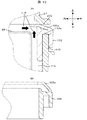
図13に気密パッキン103の断面形状を示す。図13(A)は吸気ダクト27とケース45の間に気密パッキン103が嵌め込まれた時の図で、図13(B)は気密パッキン103の単体の断面図を示している。気密パッキン103は、円環状の内部材と円環状の外部材とが、その上部の連結部を介して一体に形成されている。内部材の上部は、わずかに上側に突出している。外部材の上部には、内部材の上方へ向かって延びる排気リップ部103aが一体に形成されている。内部材と外部材と連結部との間に、ケース45の縁部110が挟み込まれる。縁部110の上面には、山部B110aが形成され、気密パッキン103の連結部に食い込んでいる。特に山部B110aよって、気密パッキン103とケース45の縁部110とが密着する。さらに、排気リップ部103aと内部材の上部とが当接することによって、気密パッキン103と吸気ダクト27のダクト気密面27bとが密着する。さらに、気密パッキン103の排気リップ部103aは、ケース45内に組み込まれた電動送風機28から矢印方向の排気圧116が高まると排気リップ部103aが外側に膨らもうとする力が働き排気リップ部103aとダクト気密面27bの接面圧力が上昇し、より排気の気密が取れるような構造となっている。本実施例では、気密パッキン103を変形量が大きく硬度の低い弾性部材としているが、耐圧性能が求められる場合、より硬度の高い弾性部材を用いてもかまわない。また、吸気ダクト27とケース45を固定する箇所は気密パッキン103を均一に変形させるため5箇所であるが、気密パッキン103を均一に変形させることができれば5箇所でなくてもよく、あるいはねじ以外の固定方法(例えば、クリップや圧入)でも構わない。
FIG. 13 shows a cross-sectional shape of the hermetic packing 103. FIG. 13A is a view when the airtight packing 103 is fitted between the intake duct 27 and the case 45, and FIG. 13B shows a sectional view of the airtight packing 103. In the hermetic packing 103, an annular inner member and an annular outer member are integrally formed via an upper connecting portion. The upper part of the inner member protrudes slightly upward. An exhaust lip 103a extending upward from the inner member is integrally formed on the upper part of the outer member. The edge 110 of the case 45 is sandwiched between the inner member, the outer member, and the connecting portion. A crest B 110 a is formed on the upper surface of the edge portion 110 and bites into the connecting portion of the airtight packing 103. In particular, the airtight packing 103 and the edge portion 110 of the case 45 are brought into close contact with each other by the mountain portion B110a. Furthermore, the airtight packing 103 and the duct airtight surface 27b of the air intake duct 27 are brought into close contact with each other when the exhaust lip 103a and the upper part of the inner member come into contact with each other. Further, the exhaust lip 103a of the airtight packing 103 has a force that causes the exhaust lip 103a to expand outwardly when the exhaust pressure 116 in the direction of the arrow is increased from the electric blower 28 incorporated in the case 45. The structure is such that the contact pressure between 103a and the duct airtight surface 27b increases, and the airtightness of the exhaust can be further increased. In this embodiment, the hermetic packing 103 is an elastic member having a large deformation amount and low hardness. However, an elastic member having higher hardness may be used when pressure resistance is required. Further, there are five places where the air intake duct 27 and the case 45 are fixed in order to uniformly deform the airtight packing 103. However, if the airtight packing 103 can be uniformly deformed, it may not be 5 places or other than screws. The fixing method (for example, clip or press fitting) may be used.
集塵装置2を通過した空気の流れを説明する。集塵装置2を通過した空気流れは、吸気ダクト27により偏向され、吸込口28aより電動送風機28内に流入する。流入した空気流れは、電動送風機28内で羽根車により昇圧され、排出口28bより吸気ダクト27とケース45により形成される空間に押し出される。排気ダクト40のケース45と反対側の開口には、フィルタ29が設けられている。吸気ダクト27とケース45により形成される空間に押し出された空気は、すべてフィルタ29を通過し、掃除機本体1内を経て大気に拡散される。集塵装置2を通過した空気流れは、集塵装置2が装備するフィルタ15が濾し取れない場合や、集塵装置2取り付け時に微細なごみが混入する可能性があり、本実施例のような、電動送風機28の下流に排気をすべて通過するフィルタ29があれば、微細なごみを濾過し、きれいな空気にすることができるため部屋の空気を汚すことがない。また、電動送風機28から発生するカーボン粉もすべてフィルタ29を通過し濾過されるため、きれいな空気を得ることができる。
The flow of air that has passed through the dust collector 2 will be described. The air flow that has passed through the dust collector 2 is deflected by the intake duct 27 and flows into the electric blower 28 from the suction port 28a. The inflowing air flow is boosted by the impeller in the electric blower 28 and pushed out from the discharge port 28b to the space formed by the intake duct 27 and the case 45. A filter 29 is provided in the opening of the exhaust duct 40 on the side opposite to the case 45. All of the air pushed out into the space formed by the intake duct 27 and the case 45 passes through the filter 29 and is diffused into the atmosphere through the cleaner body 1. The air flow that has passed through the dust collector 2 may not be filtered by the filter 15 provided in the dust collector 2, or fine dust may be mixed when the dust collector 2 is attached. If there is a filter 29 that passes all the exhaust gas downstream of the electric blower 28, fine dust can be filtered and made into clean air, so that the air in the room is not polluted. Moreover, since all the carbon powder generated from the electric blower 28 passes through the filter 29 and is filtered, clean air can be obtained.
図10に示すように、電動送風機28上部を支持する弾性部材101は、円環形状の固定カバー102によって吸気ダクト27に固定される。固定カバー102の外径は弾性部材101の外径よりも大きく、固定カバー102の内径は弾性部材101の内径よりも大きいが、固定カバー102の内径は弾性部材101の外径よりも小さい。よって、弾性部材101の外周側を固定カバー102の内周側によって覆い、固定することになる。固定カバー102の外径は、ダクト気密面27bの内径よりも小さく、固定カバー102はダクト気密面27bの内側に収容されることになる。そして、図10に示すように、吸気ダクト27の排出口27bの裏面の周囲には、円環状の位置決めリブ108が形成される。位置決めリブ108は、内外2つのリブから構成される。弾性部材101の固定用溝101cと吸気ダクト27の位置決めリブ108が接するように弾性部材101が配置され、固定カバー102で吸気ダクト27に6箇所ねじで締結される。図11に示すように、吸気ダクト27のダクト気密面27bの内周側の一箇所には位置決め凹部105が設けてあり、固定カバー102の位置決め凸部102aとの位置決めに用いられる。これによって位置決めが容易であり、組立時間を短縮することができる。
As shown in FIG. 10, the elastic member 101 that supports the upper portion of the electric blower 28 is fixed to the intake duct 27 by an annular fixed cover 102. The outer diameter of the fixed cover 102 is larger than the outer diameter of the elastic member 101, and the inner diameter of the fixed cover 102 is larger than the inner diameter of the elastic member 101, but the inner diameter of the fixed cover 102 is smaller than the outer diameter of the elastic member 101. Therefore, the outer peripheral side of the elastic member 101 is covered and fixed by the inner peripheral side of the fixed cover 102. The outer diameter of the fixed cover 102 is smaller than the inner diameter of the duct airtight surface 27b, and the fixed cover 102 is accommodated inside the duct airtight surface 27b. As shown in FIG. 10, an annular positioning rib 108 is formed around the back surface of the discharge port 27 b of the intake duct 27. The positioning rib 108 includes two inner and outer ribs. The elastic member 101 is arranged so that the fixing groove 101c of the elastic member 101 and the positioning rib 108 of the intake duct 27 are in contact with each other, and is fastened to the intake duct 27 by the fixing cover 102 with six screws. As shown in FIG. 11, a positioning recess 105 is provided at one location on the inner peripheral side of the duct airtight surface 27 b of the intake duct 27 and is used for positioning with the positioning projection 102 a of the fixed cover 102. As a result, positioning is easy and assembly time can be shortened.
吸気ダクト27からは固定カバー102を固定するねじを受けるボス104が突出している。これは、吸気ダクト27のボス104が突出する壁111の裏面は、集塵装置2からの電動送風機28への空気流れを導く風路になっているため、固定カバー102を吸気ダクト27に固定するためには、壁111の厚みを増すか、風路に突起を設ける必要がある。固定カバー102を皿ねじで固定することで、壁111の厚みを増さず、風路に突起物を出さずに固定カバー102を吸気ダクト27に固定することができる。また、ねじと電動送風機28との当接を防止することができる。
A boss 104 for receiving a screw for fixing the fixed cover 102 protrudes from the intake duct 27. This is because the back surface of the wall 111 from which the boss 104 of the intake duct 27 protrudes is an air path that guides the air flow from the dust collector 2 to the electric blower 28, so that the fixed cover 102 is fixed to the intake duct 27. In order to do this, it is necessary to increase the thickness of the wall 111 or to provide a protrusion on the air passage. By fixing the fixed cover 102 with a countersunk screw, the fixed cover 102 can be fixed to the intake duct 27 without increasing the thickness of the wall 111 and without projecting a protrusion in the air passage. Further, the contact between the screw and the electric blower 28 can be prevented.
図12は、本実施例の弾性部材の斜視図である。弾性部材101は、円環状の基体に、防振機能を果たす防振突起101eと気密保持機能を果たす防振部材気密部101aとが一体に形成されている。基体,防振突起101e,防振部材気密部101aとは同一材料で構成されるのが好ましい。防振突起101eは、防振部材気密部101aの内周側に形成された円環状の突出した部分に、8箇所設けてある。防振突起101eの先端が、ケーシング面28cに当接する。この防振突起101eは、突起同士が独立しているため吸気ダクト27がケース45にねじで締結されると防振突起101eの先端は突起同士の間に潰れ代が入り込み電動送風機28が弾性部材101で固定され、振動を抑制することができる。防振突起101eは押し潰された状態でも、複数の防振突起101e間に隙間が残っていてもよい。本実施例では、防振突起101eが8個に分かれているが、防振突起101eの数量が違っていても、リング状に繋がっていても良い。防振部材気密部101aは、防振突起101eの外周側に形成される。防振部材気密部101aは、円環状の薄板で構成されるが、根元に対して先端が外周側に拡がっている。防振部材気密部101aの先端が、ケーシング面28cに当接する。防振部材気密部101aは薄板で構成されているため、防振突起101eと同一の材料(例えば、ゴムなど)で構成されても、防振突起101eよりも剛性が低く、弾性変形しやすい。円環状に配置された防振突起101eと円環状の防振部材気密部101aとは同心円上の位置関係となるのが好ましい。防振突起101eを内周側、防振部材気密部101aを外周側に配置する代わりに、防振部材気密部101aを内周側、防振突起101eを外周側に配置してもよい。
FIG. 12 is a perspective view of the elastic member of the present embodiment. In the elastic member 101, an anti-vibration protrusion 101e that performs a vibration-proof function and a vibration-proof member hermetic portion 101a that performs a hermetic holding function are integrally formed on an annular base. It is preferable that the base, the vibration isolating protrusion 101e, and the vibration isolating member airtight portion 101a are made of the same material. The anti-vibration protrusions 101e are provided at eight locations on the annular protruding portion formed on the inner peripheral side of the anti-vibration member airtight part 101a. The tip of the anti-vibration protrusion 101e contacts the casing surface 28c. Since the anti-vibration protrusions 101e are independent from each other, when the intake duct 27 is fastened to the case 45 with screws, the tip of the anti-vibration protrusion 101e is crushed between the protrusions and the electric blower 28 is an elastic member. It is fixed at 101 and vibration can be suppressed. Even if the anti-vibration protrusions 101e are crushed, gaps may remain between the anti-vibration protrusions 101e. In this embodiment, the anti-vibration protrusions 101e are divided into eight pieces, but the number of anti-vibration protrusions 101e may be different or connected in a ring shape. The anti-vibration member hermetic portion 101a is formed on the outer peripheral side of the anti-vibration protrusion 101e. The vibration-proof member hermetic portion 101a is formed of an annular thin plate, but the tip extends to the outer peripheral side with respect to the root. The tip of the vibration-proof member airtight portion 101a contacts the casing surface 28c. Since the anti-vibration member hermetic portion 101a is made of a thin plate, even if it is made of the same material (for example, rubber) as the anti-vibration projection 101e, the anti-vibration projection 101e is less rigid and easily elastically deformed. It is preferable that the anti-vibration protrusion 101e arranged in an annular shape and the annular anti-vibration member hermetic portion 101a have a concentric positional relationship. Instead of arranging the anti-vibration protrusion 101e on the inner peripheral side and the anti-vibration member airtight part 101a on the outer peripheral side, the anti-vibration member air-tight part 101a may be arranged on the inner peripheral side and the anti-vibration protrusion 101e on the outer peripheral side.
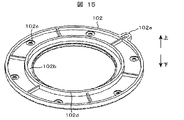
図15は、本実施例の固定カバーを吸気ダクト側からみた斜視図を示す。図15に示すように、固定カバー102は、円環形状を有する。固定カバー102の最内周部は、円環状の気密面102bが形成される。気密面102bの外周には、円筒状に突出したリブ102dが形成される。また、リブ102dの外周には、ねじが挿入可能な取り付け孔102cが周方向に6箇所形成される。固定カバー102の最外周の一箇所に位置決め凸部102aが外周側に突出して形成される。インサート形成などによって弾性部材101が吸気ダクト27に固定可能な場合は、固定カバー102はなくてもよい。
FIG. 15 is a perspective view of the fixed cover of this embodiment as viewed from the intake duct side. As shown in FIG. 15, the fixed cover 102 has an annular shape. An annular airtight surface 102 b is formed on the innermost peripheral portion of the fixed cover 102. A rib 102d protruding in a cylindrical shape is formed on the outer periphery of the airtight surface 102b. Further, six attachment holes 102c into which screws can be inserted are formed in the outer periphery of the rib 102d in the circumferential direction. A positioning projection 102a is formed at one location on the outermost periphery of the fixed cover 102 so as to protrude outward. When the elastic member 101 can be fixed to the intake duct 27 by forming an insert or the like, the fixing cover 102 may not be provided.
図14(A)は、本実施例の吸気ダクトと固定カバーと弾性部材の片側の断面図であり、図14(B)は、本実施例の弾性部材の片側の断面図を示す。図14(B)に示すように、弾性部材101の基体の上面は凹んでおり、円環状の固定用溝101cを形成する。基体の最外周には円筒状の気密部101bが形成され、気密部101bの下端は下側へ突出し、凸部101dを形成する。固定カバー102がなければ、凸部101dはなくてもよい。基体の下面のうち固定用溝101cに対応する部分で、さらに固定用溝101cに対応する部分のうちの内側は下側へ突出しており、その突出した部分に、防振突起101eが形成される。防振突起101eの突出方向は、上下方向であり、これは弾性部材101が吸気ダクト27および電動送風機28から圧縮力を受ける方向である。尚、下側へ突出した部分は、円環形状を有する。基体の下面のうち固定用溝101cに対応する部分で、さらに固定用溝101cに対応する部分のうちの外側には、防振部材気密部101aが形成される。防振部材気密部101aは、数mm程度の薄板で構成され、円筒形状を有する。防振部材気密部101aの板厚は、防振突起101eの半径方向の厚みよりも小さい。防振部材気密部101aの上下方向中央より上側(根元側)は、上下方向に形成され、上下方向中央より下側(先端側)は、上下方向(軸方向)を基準にすると略60度程度、水平方向(半径方向)を基準にすると略30度程度、外側へ拡がって形成され、防振部材気密部101aの先端は、凸部101dの下方にまで達している。そして、図14(B)に示すように、防振部材気密部101aの先端の位置は、弾性部材101の基体を基準にすると防振突起101eの先端の位置よりも突出している。つまり、防振部材気密部101aは、途中から外側へ屈曲している。ただし、防振部材気密部101aは、根元端から外側へ拡がっていてもよい。防振部材気密部101aの屈曲部分の上下方向の位置は、防振突起101eの根元端の上下方向の位置にほぼ相当する。防振部材気密部101aの屈曲部分の根元側は、防振部材気密部101aの一部として薄板で構成されるのに対して、防振突起101eの根元は、基体の下側へ突出した部分で構成されることになる。
FIG. 14A is a cross-sectional view of one side of the intake duct, the fixed cover, and the elastic member of the present embodiment, and FIG. 14B is a cross-sectional view of one side of the elastic member of the present embodiment. As shown in FIG. 14B, the upper surface of the base body of the elastic member 101 is recessed, and an annular fixing groove 101c is formed. A cylindrical airtight portion 101b is formed on the outermost periphery of the base, and the lower end of the airtight portion 101b protrudes downward to form a convex portion 101d. If there is no fixed cover 102, the convex portion 101d may be omitted. Of the lower surface of the base, the portion corresponding to the fixing groove 101c and the inner portion of the portion corresponding to the fixing groove 101c protrude downward, and the anti-vibration protrusion 101e is formed in the protruding portion. . The protruding direction of the anti-vibration protrusion 101e is the vertical direction, which is the direction in which the elastic member 101 receives a compressive force from the intake duct 27 and the electric blower 28. Note that the portion protruding downward has an annular shape. An anti-vibration member hermetic portion 101a is formed on the lower surface of the base portion corresponding to the fixing groove 101c and on the outer side of the portion corresponding to the fixing groove 101c. The vibration-proof member hermetic portion 101a is formed of a thin plate of about several mm and has a cylindrical shape. The plate thickness of the vibration-proof member hermetic portion 101a is smaller than the radial thickness of the vibration-proof projection 101e. The upper side (base side) of the anti-vibration member airtight portion 101a is formed in the vertical direction, and the lower side (tip side) of the vertical center is about 60 degrees with respect to the vertical direction (axial direction). When the horizontal direction (radial direction) is used as a reference, the outer side is formed to extend outward by about 30 degrees, and the tip of the vibration-proof member airtight part 101a reaches the lower part of the convex part 101d. As shown in FIG. 14B, the position of the tip of the vibration-proof member hermetic portion 101a protrudes from the position of the tip of the vibration-proof projection 101e when the base of the elastic member 101 is used as a reference. That is, the vibration-proof member airtight portion 101a is bent outward from the middle. However, the vibration-proof member hermetic portion 101a may extend outward from the root end. The vertical position of the bent portion of the vibration-proof member hermetic portion 101a substantially corresponds to the vertical position of the root end of the vibration-proof projection 101e. The base side of the bent portion of the vibration-proof member airtight portion 101a is formed of a thin plate as a part of the vibration-proof member airtight portion 101a, whereas the root of the vibration-proof member 101e is a portion protruding to the lower side of the base body. It will consist of
図14(A)に示すように、弾性部材101は、吸込口28aの縁を形成する円環状の目玉部28dの外側に配置される。弾性部材101の内周面は目玉部28dの外周面に当接するように弾性部材101が配置される。これによって、電動送風機28の上部の半径方向への位置ずれを抑制している。弾性部材101の凸部101dの下面が固定カバー102の気密面102bの上面に当接し、吸気ダクト27の壁111の下面に弾性部材101の気密部101bの上面が当接することによって、弾性部材101は、固定カバー102によって吸気ダクト27の壁111に固定される。気密部101bは、固定カバー102がねじにより締結されると、気密面102bと壁111から圧力を受ける。圧力を受けた気密部101bは、隙間112内で変形し、変形分の反力を気密面102bと壁111に対して発生させる。また、吸気ダクト27の壁111の気密部101bに対応する位置に設けた円環状の山部27cが気密部101bに突き刺さり吸気ダクト27と弾性部材101の気密を保持することができる。一方、弾性部材101と電動送風機28の気密を保持するために防振部材気密部101aが設けてある。防振部材気密部101aは薄板でかつ外側へ拡がって構成されるため、電動送風機28のケーシング面28cに当接すると防振部材気密部101aの先端が弾性変形してたわみ、電動送風機28からの排気圧116および電動送風機28の吸込圧117の力に対し、電動送風機28の運転状態ではケーシング面28cに押し付き、気密が確保される。防振部材気密部101aが接触するケーシング面28cと防振突起101eが接触するケーシング面とは、一直線状に形成されるが、その間に溝を有する。防振部材気密部101aの先端は吸排気圧のかかる方向(半径方向の内側の方向)に対し変形し追従し易いように薄板状になっている。防振部材気密部101aの先端は外側に略30度広がって構成されており、組み込み時には防振部材気密部101aの先端が30度よりも押し潰されて組み込まれる。これにより、防振部材気密部101a自身がケーシング面28cに常に押し付けられ気密を保つ働きがある。さらに、組み込み前状態(初期状態)において、防振部材気密部101aの先端は、外側に広がって構成しているため作業者が組み込む時に防振部材気密部101aの先端がめくれる心配をしなくても良く、安定して組み込むことができる。
As shown in FIG. 14A, the elastic member 101 is disposed outside the annular eyeball portion 28d that forms the edge of the suction port 28a. The elastic member 101 is disposed so that the inner peripheral surface of the elastic member 101 contacts the outer peripheral surface of the eyeball portion 28d. Thereby, the positional deviation to the radial direction of the upper part of the electric blower 28 is suppressed. The lower surface of the convex portion 101 d of the elastic member 101 contacts the upper surface of the airtight surface 102 b of the fixed cover 102, and the upper surface of the airtight portion 101 b of the elastic member 101 contacts the lower surface of the wall 111 of the intake duct 27. Is fixed to the wall 111 of the intake duct 27 by the fixed cover 102. The airtight portion 101b receives pressure from the airtight surface 102b and the wall 111 when the fixed cover 102 is fastened by screws. The airtight portion 101 b that has received the pressure is deformed in the gap 112, and a reaction force for the deformation is generated on the airtight surface 102 b and the wall 111. In addition, an annular crest 27c provided at a position corresponding to the airtight portion 101b of the wall 111 of the intake duct 27 pierces the airtight portion 101b, and the airtightness of the intake duct 27 and the elastic member 101 can be maintained. On the other hand, a vibration-proof member hermetic portion 101a is provided to keep the elastic member 101 and the electric blower 28 hermetic. Since the vibration-proof member hermetic portion 101a is a thin plate and extends outward, the tip of the vibration-proof member hermetic portion 101a bends due to elastic deformation when coming into contact with the casing surface 28c of the electric blower 28. The exhaust pressure 116 and the suction pressure 117 of the electric blower 28 are pressed against the casing surface 28c in the operating state of the electric blower 28, and airtightness is ensured. The casing surface 28c in contact with the vibration-proof member airtight portion 101a and the casing surface in contact with the vibration-proof projection 101e are formed in a straight line, but have a groove therebetween. The tip of the vibration-proof member hermetic portion 101a has a thin plate shape so as to easily deform and follow the direction in which the intake / exhaust pressure is applied (the inner direction in the radial direction). The tip of the vibration-proof member hermetic portion 101a is configured to extend approximately 30 degrees outward, and when assembled, the tip of the vibration-proof member hermetic portion 101a is crushed more than 30 degrees and incorporated. As a result, the vibration-proof member hermetic portion 101a itself is always pressed against the casing surface 28c and has the function of keeping the hermeticity. Furthermore, in the state before the assembly (initial state), the tip of the vibration-proof member hermetic portion 101a is configured to spread outward, so that the operator does not have to worry about the tip of the vibration-proof member hermetic portion 101a turning over when assembled. And can be incorporated stably.
図14(A)に示すように、防振突起101eの根元部分である基体の下側への突出部分と吸気ダクト27の位置決めリブ108との間には、空間(固定用溝101c)が残されている。よって、弾性部材101が吸気ダクト27と電動送風機28によって押しつぶされると、防振突起101eが弾性変形するだけでなく、防振突起101eの根元部分である基体の下側への突出部分も弾性変形する。弾性変形後も防振突起101eの根元部分である基体の下側への突出部分と吸気ダクト27の位置決めリブ108との間には、空間(固定用溝101c)が残されているため、剛性が高くならず、電動送風機28の振動が吸気ダクト27へ伝達しにくい。一方、図14(A)に示すように、防振部材気密部101aの根元部分にあたる基体部分と位置決めリブ108との間には、空間(固定用溝101c)が残されていない。そもそも防振部材気密部101aは、薄板でかつ外側へ拡がって構成されるため、防振突起101eよりも剛性が低く、電動送風機28の振動が吸気ダクト27へ伝達しにくいので、防振部材気密部101aの根元部分にあたる基体部分を変形させる必要がなく、隙間を空ける必要がない。そして、本実施例では、電動送風機28との防振,気密を別々の形状で構成しているため、防振に最適な形状と気密に最適な形状を得ることができる。本実施例では、硬度約40度の合成ゴムを弾性部材101に使用しているが、振動の影響に応じて硬度を変えても良い。その際、防振部材気密部101aは硬度の影響を受けにくい薄板状のため気密を保つことができる。
As shown in FIG. 14 (A), a space (fixing groove 101c) remains between the protruding portion of the base body, which is the base portion of the anti-vibration protrusion 101e, and the positioning rib 108 of the intake duct 27. Has been. Therefore, when the elastic member 101 is crushed by the intake duct 27 and the electric blower 28, not only the anti-vibration projection 101e is elastically deformed, but also the protruding portion of the base, which is the base portion of the anti-vibration projection 101e, is elastically deformed. To do. Even after the elastic deformation, the space (fixing groove 101c) remains between the protruding portion of the base body, which is the base portion of the anti-vibration projection 101e, and the positioning rib 108 of the intake duct 27. The vibration of the electric blower 28 is not easily transmitted to the intake duct 27. On the other hand, as shown in FIG. 14A, no space (fixing groove 101c) is left between the base portion corresponding to the root portion of the vibration-proof member airtight portion 101a and the positioning rib 108. In the first place, since the vibration-proof member airtight portion 101a is a thin plate and extends outward, the vibration-proof member airtight portion 101a is less rigid than the vibration-proof projection 101e, and the vibration of the electric blower 28 is difficult to transmit to the intake duct 27. It is not necessary to deform the base portion corresponding to the base portion of the portion 101a, and it is not necessary to leave a gap. In this embodiment, since the vibration isolation and airtightness with the electric blower 28 are configured in different shapes, it is possible to obtain an optimal shape for vibration isolation and an optimal shape for airtightness. In this embodiment, synthetic rubber having a hardness of about 40 degrees is used for the elastic member 101, but the hardness may be changed according to the influence of vibration. At this time, since the vibration-proof member airtight portion 101a is a thin plate that is not easily affected by hardness, it can be kept airtight.
吸気ダクト27に固定された弾性部材101は、電動送風機28のケーシング面28cに防振気密部101aを接触する。吸気ダクト27とケース45がねじ止め107で固定されると、防振気密部101aは、電動送風機28と吸気ダクト27の壁111に押され、防振気密部101aおよび凸部101dは、隙間112やその周辺で変形する。この変形は反力となり防振気密部101aとケーシング面28cの間で、接面圧力を上昇させる。このため、防振気密部101aとケーシング面28cの気密が保持される。電動送風機28は集塵装置2から空気流れを吸気ダクト27を介して吸込み、羽根車で昇圧し、排気口28bからケース45内に押し出している。したがって、弾性部材101の吸込側空間114は負圧、排気側空間115は正圧になる。弾性部材101は、防振気密部101aと気密部101bで吸込側空間114と排気側空間115の気密を保持しているため、排気側空間115から吸気側空間114に空気が流れるのを防ぎ、吸込性能の低下および排気の循環を防止している。弾性部材101は、電動送風機28を支持してなお周囲に隙間112が存在し、柔らかく電動送風機28を保持している。このため、弾性部材101は電動送風機28から吸気ダクト27への振動の伝達を抑制することができる。本実施例では、合成ゴムを弾性部材101に使用しているが、さらに硬度の低いゴム等を使用し、吸気ダクト27への振動伝達量を低減してもよい。
The elastic member 101 fixed to the intake duct 27 contacts the vibration-proof and airtight portion 101 a with the casing surface 28 c of the electric blower 28. When the intake duct 27 and the case 45 are fixed with screws 107, the vibration-proof airtight portion 101 a is pushed by the electric blower 28 and the wall 111 of the intake duct 27, and the vibration-proof airtight portion 101 a and the convex portion 101 d have a gap 112. Deforms around and around. This deformation becomes a reaction force and increases the contact pressure between the vibration-proof airtight portion 101a and the casing surface 28c. For this reason, the airtightness of the vibration-proof airtight part 101a and the casing surface 28c is maintained. The electric blower 28 sucks the air flow from the dust collector 2 through the intake duct 27, pressurizes it with an impeller, and pushes it out into the case 45 through the exhaust port 28b. Therefore, the suction side space 114 of the elastic member 101 has a negative pressure and the exhaust side space 115 has a positive pressure. Since the elastic member 101 maintains the airtightness of the suction side space 114 and the exhaust side space 115 by the vibration-proof airtight portion 101a and the airtight portion 101b, air is prevented from flowing from the exhaust side space 115 to the intake side space 114, Reduced suction performance and exhaust circulation. The elastic member 101 supports the electric blower 28 and still has a gap 112 around it, and softly holds the electric blower 28. For this reason, the elastic member 101 can suppress transmission of vibration from the electric blower 28 to the intake duct 27. In this embodiment, synthetic rubber is used for the elastic member 101, but rubber having lower hardness may be used to reduce the amount of vibration transmitted to the intake duct 27.
電動送風機28は、下側を防振材113を介してケース45に支えられている。防振材113は、振動がケース45に伝達するのを防止するたけでなく、電動送風機28が回転することを防止している。本実施例では、合成ゴムを使用しているが、さらに硬度の低いゴムを使用し、ケース45への振動伝達量を低減してもよい。
The lower side of the electric blower 28 is supported by the case 45 via a vibration isolating material 113. The anti-vibration material 113 not only prevents vibration from being transmitted to the case 45 but also prevents the electric blower 28 from rotating. In the present embodiment, synthetic rubber is used, but rubber having lower hardness may be used to reduce the amount of vibration transmitted to the case 45.
次に、電気掃除機の騒音について説明する。電気掃除機は、内蔵する電動送風機28により3つの代表的な騒音を発生させる。
Next, the noise of a vacuum cleaner will be described. The vacuum cleaner generates three typical noises by the built-in electric blower 28.
一つ目は、流れの乱れに起因する、広い帯域にわたって発生する乱流騒音である。本実施例のような掃除機本体1では、内蔵する電動送風機28の回転数は無負荷時で毎分36000回転以上と速く、風量も2m3/minと多い。電動送風機28内部や掃除機本体1内は流路が狭いため、電動送風機28により発生した空気流れは、局所的に高速な乱れた流れとなり乱流騒音を発生させる。
The first is turbulent noise generated over a wide band due to flow disturbance. In the vacuum cleaner main body 1 as in the present embodiment, the number of rotations of the built-in electric blower 28 is as fast as 36000 revolutions per minute when no load is applied, and the air volume is as high as 2 m 3 / min. Since the flow path is narrow inside the electric blower 28 and the vacuum cleaner main body 1, the air flow generated by the electric blower 28 is locally turbulent and generates turbulent noise.
二つ目は、羽根車の羽根の数と回転数の積の整数倍の周波数を有する羽根音である。電動送風機28の羽根車は、羽根の表面に圧力差を生じさせることで、流体を駆動させる。そのため、本実施例のように羽根車の下流に静止翼を持つ電動送風機では、静止翼と羽根車の境界で圧力差が生じ、それが変動するため、羽根車の羽根の数と回転数の積の整数倍の周波数を有する羽根音が発生しやすい。
The second is a blade sound having a frequency that is an integral multiple of the product of the number of impeller blades and the number of rotations. The impeller of the electric blower 28 drives the fluid by generating a pressure difference on the surface of the blade. Therefore, in the electric blower having stationary blades downstream of the impeller as in the present embodiment, a pressure difference is generated at the boundary between the stationary blades and the impeller, and it fluctuates. It is easy to generate a blade sound having a frequency that is an integral multiple of the product.
三つ目は、回転数の周波数の音を有する回転振動音である。電動送風機28はロータ、及びステータ間の電磁力により羽根車を回転させ、羽根の運動により羽根車の前後に差圧を生じ吸引力を発生させる回転機械である。回転機械は、回転軸周りに多少偏心アンバランスを残留させており、軸受に回転周期の加振力を発生させる。電動送風機は、ロータ,羽根車に偏心アンバランスを持ち、これらが回転することで、軸受への周期的な加振力を発生させ、これが回転振動となる。軸受に伝わった回転振動は一部は電動送風機の表面から、その他は、電動送風機を支持する部材から振動として伝播し、掃除機本体を加振し、大気に音として放射される。これが回転振動音である。
The third is a rotational vibration sound having a sound with a frequency of the rotational speed. The electric blower 28 is a rotating machine that rotates the impeller by electromagnetic force between the rotor and the stator, and generates a suction force by generating a differential pressure before and after the impeller by the movement of the impeller. The rotating machine has a slight eccentric imbalance around the rotating shaft, and generates an exciting force with a rotation period in the bearing. The electric blower has an eccentric imbalance in the rotor and the impeller, and these rotate to generate a periodic exciting force on the bearing, which becomes rotational vibration. A part of the rotational vibration transmitted to the bearing propagates as vibration from the surface of the electric blower and the other from the member that supports the electric blower, vibrates the main body of the cleaner, and is emitted as sound to the atmosphere. This is rotational vibration sound.
本実施例は、回転振動音による低周波の不快な騒音を低減することにより掃除機騒音を改善できる。回転振動音を低減するためには、発生源である電動送風機の偏心アンバランスを低減し、回転振動を抑制する方法と、電動送風機からの伝播経路で回転振動を低減する方法が考えられる。本実施例では後者により改善する。
This embodiment can improve cleaner noise by reducing unpleasant low-frequency noise caused by rotational vibration noise. In order to reduce the rotational vibration noise, there are a method of reducing the eccentric imbalance of the electric blower that is the generation source and suppressing the rotational vibration, and a method of reducing the rotational vibration in the propagation path from the electric blower. In this embodiment, the latter is improved.
本実施例のように、電動送風機28の下流にフィルタ29を備えるような電気掃除機の場合、フィルタ29をごみが多量に通過すると、目が詰まってしまう問題があった。このような場合、本実施例のような電気掃除機では、20kPa以上の正圧が排気側空間115に加わる。このため、気密面は、その圧力に耐えうる構造にするため、しっかり押さえつける必要があった。ところが、回転振動音を低減するため、回転振動の伝達抑制を考えると、気密面をしっかりと押さえつけると剛性が上がるため、振動の伝達量が大きくなってしまう。そこで、本実施例では、防振を抑える面と気密を保つ面を別々に構成した。電動送風機28は、上側を弾性部材101を介して吸気ダクト27に、下側を防振材113を介してケース45に支持される。電動送風機28の回転振動は、弾性部材101および防振材113から、回転軸に垂直な方向とスラスト方向に伝播される。このため、電動送風機28の垂直な方向とスラスト方向を支持する剛性を下げる必要がある。
In the case of the electric vacuum cleaner including the filter 29 downstream of the electric blower 28 as in this embodiment, there is a problem that the eyes are clogged when a large amount of dust passes through the filter 29. In such a case, in the vacuum cleaner such as the present embodiment, a positive pressure of 20 kPa or more is applied to the exhaust side space 115. For this reason, the airtight surface has to be pressed firmly in order to have a structure that can withstand the pressure. However, in consideration of suppression of rotational vibration transmission in order to reduce rotational vibration noise, if the airtight surface is pressed firmly, the rigidity increases, and the amount of vibration transmission increases. Therefore, in this embodiment, the surface that suppresses vibration isolation and the surface that maintains airtightness are configured separately. The upper side of the electric blower 28 is supported by the intake duct 27 via the elastic member 101, and the lower side is supported by the case 45 via the vibration isolator 113. The rotational vibration of the electric blower 28 is propagated from the elastic member 101 and the vibration isolator 113 in the direction perpendicular to the rotation axis and in the thrust direction. For this reason, it is necessary to lower the rigidity of supporting the vertical direction and the thrust direction of the electric blower 28.
本実施例では、弾性部材101により、電動送風機28を柔らかく支持することにより、スラスト方向の振動の伝播を低減させる。また、隙間112を設けることで、防振突起101eは、電動送風機28の回転軸に垂直な方向も柔らかく支持し、振動の伝播を低減させる。このため、本体に伝わる回転振動は小さくなり、回転振動音を低減することができる。
In this embodiment, the elastic member 101 softly supports the electric blower 28 to reduce the propagation of vibration in the thrust direction. Further, by providing the gap 112, the anti-vibration protrusion 101e softly supports the direction perpendicular to the rotation axis of the electric blower 28, and reduces vibration propagation. For this reason, rotational vibration transmitted to the main body is reduced, and rotational vibration noise can be reduced.
また、別形状で設けた防振部材気密面101aは、電動送風機28のケーシング面28cに当接すると先端がたわむ構成となっており、電動送風機28からの排気圧116および電動送風機28の吸込圧117の力に対し、電動送風機28が運転するとケーシング面28cに押し付き、気密が確保される。また、防振部材気密部101aの先端は吸排気圧のかかる方向に対し変形し追従し易いように薄板状になっている。また、防振部材気密部101aの先端は外側に略30度広がって構成されており、組み込み時には防振部材気密部101aの先端が30度よりも押し潰されて組み込まれる。これにより、防振部材気密部101a自身がケーシング面28cに常に押し付けられ気密を保つ働きがある。さらに、組み込み前状態(初期状態)において、防振部材気密部101aの先端は、外側に広がって構成しているため作業者が組み込む時に防振部材気密部101aの先端がめくれる心配をしなくても良く、安定して組み込むことができる。このため、電動送風機28の排気側空間115から吸込側空間114への逆流を防止し、吸込性能を低下させることを防いでいる。
Further, the vibration-proof member airtight surface 101a provided in a different shape is configured such that the tip is bent when it comes into contact with the casing surface 28c of the electric blower 28. The exhaust pressure 116 from the electric blower 28 and the suction pressure of the electric blower 28 When the electric blower 28 is operated with respect to the force 117, the electric blower 28 is pressed against the casing surface 28c to ensure airtightness. Further, the tip of the vibration-proof member hermetic portion 101a has a thin plate shape so as to easily deform and follow the direction in which the intake / exhaust pressure is applied. Further, the tip of the vibration-proof member hermetic portion 101a is configured to extend outward by approximately 30 degrees, and when assembled, the tip of the vibration-proof member hermetic portion 101a is crushed more than 30 degrees and incorporated. As a result, the vibration-proof member hermetic portion 101a itself is always pressed against the casing surface 28c and has the function of keeping the hermeticity. Furthermore, in the state before the assembly (initial state), the tip of the vibration-proof member hermetic portion 101a is configured to spread outward, so that the operator does not have to worry about the tip of the vibration-proof member hermetic portion 101a turning over when assembled. And can be incorporated stably. For this reason, the backflow from the exhaust side space 115 of the electric blower 28 to the suction side space 114 is prevented, and deterioration of the suction performance is prevented.
図2(A)に、本発明の実施例の集塵装置の斜視図を示し、図2(B)に、本発明の実施例の集塵装置の横断面図を示す。使用者は、把手16を握って集塵装置2を上方へ持ち上げることによって、掃除機本体1から集塵装置2を取り外すことができる。ただし、塵埃分離部4を掃除機本体1に残して、塵埃収容部5のみを掃除機本体1から取り外すようにしてもよい。図2(A)に示すように、軸方向から見た塵埃分離部4の断面の外形状は、略円形状である。塵埃収容部5の断面の外形状は、前蓋11の部分では略円形状であるが、前蓋11の部分以降では略四角形状であり、フィルタ15の部分でも略四角形状である。図2(B)に示すように、ケース10の軸方向一端の開口方向とケース10の軸方向他端の開口方向とは一直線上になく、45°〜50°程度異なる。つまり、塵埃収容部5の軸方向は、中間よりも少し前側で、曲がっている。上述したが、集塵装置2の軸方向一端面(入口管3の部分)は、わずかに下方向(重力作用方向)を向き、集塵装置2の軸方向他端面(フィルタ15の部分)も、わずかに下方向(重力作用方向)を向いており、集塵装置2の軸方向一端面と軸方向他端面とは、垂直面(重力作用方向)を基準として、逆ハの字形状となるため、集塵装置2を上方へ持ち上げる際に引っかかりが少なくなり、使用者は、集塵装置2を掃除機本体1から容易に取り外すことができる。
FIG. 2A shows a perspective view of the dust collector of the embodiment of the present invention, and FIG. 2B shows a cross-sectional view of the dust collector of the embodiment of the present invention. The user can remove the dust collector 2 from the cleaner body 1 by holding the handle 16 and lifting the dust collector 2 upward. However, the dust separator 4 may be left in the cleaner body 1 and only the dust container 5 may be removed from the cleaner body 1. As shown in FIG. 2A, the outer shape of the cross section of the dust separation portion 4 viewed from the axial direction is a substantially circular shape. The outer shape of the cross section of the dust container 5 is substantially circular at the front lid 11, but is substantially square after the front lid 11, and is also substantially square at the filter 15. As shown in FIG. 2B, the opening direction at one axial end of the case 10 and the opening direction at the other axial end of the case 10 are not in a straight line and differ by about 45 ° to 50 °. That is, the axial direction of the dust container 5 is bent slightly forward from the middle. As described above, one end surface in the axial direction of the dust collector 2 (portion of the inlet pipe 3) faces slightly downward (the direction of gravity action), and the other end surface in the axial direction of the dust collector 2 (portion of the filter 15) is also , Slightly facing downward (gravity acting direction), one end surface in the axial direction and the other end surface in the axial direction of the dust collector 2 have an inverted C shape with respect to the vertical surface (gravity acting direction). Therefore, when the dust collector 2 is lifted upward, the amount of catch is reduced, and the user can easily remove the dust collector 2 from the cleaner body 1.
図3(A)に、本発明の実施例の内筒および外筒の斜視図を示し、図3(B)に、本発明の実施例の内筒の裏側の斜視図を示す。外筒6の一端面は、入口管3の形成部分を除き、閉塞し、外筒6の他端面は、開口する。内筒7は、円筒部分の一端に、円環状の外延部34を有する。図3(A)に示すように、外筒6内に軸方向に内筒7の円筒部分から挿入されることによって、外筒6の他端面の外周端が外延部34の外周端に当接して、外筒6内に内筒7が形成される。図3(A)に示すように、入口管3の開口方向と凹み部8の開口とは対向している。凹み部8の内筒7の外周端部への開口方向は略下向きであり、案内管38の円周方向の開口方向は、反時計周りである。尚、案内管38の円周方向の開口方向は、時計周りであってもよい。そして、外延部34の上部に、軸方向に貫通する孔を備え、つまり外延部34の上部が開口している。開口の左壁面は、右壁面に比較して高くなっている。つまり、案内管38の円周方向の開口方向に対向する外延部34の上部の開口の壁面(左壁面)が他の壁面(右壁面)より高くなっている。そして、外延部34の表面はらせん状になっており、空気を外延部34の上部の開口に滑らかに導く流路の機能を有する。図3(B)に示すように、内筒7内の上側略半円部分に、内筒7の内側へ向かって凹み閉塞した凹み部39を備え、下側略半円部分は、内筒7内に開口している。集塵かご12に塵埃が堆積していない状態において内筒7内の空気の流量より内筒7外の空気の流量を多くする場合は、内筒7内の開口面積よりも外延部34上部の開口面積を大きくしてもよい。内筒7内への開口に比較して凹み部39の領域を多くしてもよいし、凹み部39に比較して内筒7内への開口の領域を多くしてもよい。そして、使用者は凹み部39に指を入れて、容易に塵埃分離部4あるいは内筒7を持つことができる。
FIG. 3A shows a perspective view of the inner cylinder and the outer cylinder of the embodiment of the present invention, and FIG. 3B shows a perspective view of the back side of the inner cylinder of the embodiment of the present invention. One end surface of the outer cylinder 6 is closed except for a portion where the inlet pipe 3 is formed, and the other end surface of the outer cylinder 6 is opened. The inner cylinder 7 has an annular extending portion 34 at one end of the cylindrical portion. As shown in FIG. 3A, the outer peripheral end of the other end surface of the outer cylinder 6 abuts on the outer peripheral end of the outer extension part 34 by being inserted into the outer cylinder 6 from the cylindrical portion of the inner cylinder 7 in the axial direction. Thus, the inner cylinder 7 is formed in the outer cylinder 6. As shown in FIG. 3A, the opening direction of the inlet pipe 3 and the opening of the recessed portion 8 are opposed to each other. The opening direction of the recess 8 toward the outer peripheral end of the inner cylinder 7 is substantially downward, and the opening direction of the guide tube 38 in the circumferential direction is counterclockwise. The circumferential opening direction of the guide tube 38 may be clockwise. And the hole penetrated to an axial direction is provided in the upper part of the outward extension part 34, ie, the upper part of the outward extension part 34 is opening. The left wall surface of the opening is higher than the right wall surface. That is, the wall surface (left wall surface) of the upper opening of the extension part 34 facing the opening direction in the circumferential direction of the guide tube 38 is higher than the other wall surface (right wall surface). The surface of the extended portion 34 is spiral, and has a function of a flow path that smoothly guides air to the opening above the extended portion 34. As shown in FIG. 3 (B), the upper substantially semicircular portion in the inner cylinder 7 is provided with a recessed portion 39 that is recessed toward the inner side of the inner cylinder 7, and the lower substantially semicircular portion is formed in the inner cylinder 7. Open in. When the flow rate of air outside the inner cylinder 7 is made larger than the flow rate of air inside the inner cylinder 7 in a state where dust is not accumulated in the dust collecting basket 12, the upper portion of the extended portion 34 is higher than the opening area inside the inner cylinder 7. The opening area may be increased. The area of the recessed portion 39 may be increased as compared with the opening into the inner cylinder 7, or the area of the opening into the inner cylinder 7 may be increased as compared with the recessed portion 39. Then, the user can easily hold the dust separation part 4 or the inner cylinder 7 by putting his / her finger into the recess 39.
内筒7の円筒部を抗菌効果のある金属材料で形成する場合は、先ず、金属の薄板に、直径0.1mm〜0.4mm程度の複数の貫通孔33をエッチング加工し、その後、両端を接合して円筒形状にする。貫通孔33はパンチング加工でもよい。抗菌効果のある金属材料として、例えば、ステンレス,銀,銅などがある。ステンレス,銀,銅に限らず、銀や銅を含むまたは銀や銅が表面析出した合金であればよい。金属の薄板の厚さは1mm以下であり、加工性を向上するには0.1mm〜0.5mm程度が好ましい。金属薄板の厚さが薄い場合には、強度を向上したり、真円度を向上するために、円筒状の金属薄板の軸方向の両端を、成形性のよい樹脂で固定するのが好ましい。具体的には、凹み部8や案内管38を有する内筒7の略円形状の一端部の型および円環状の外延部34を有する内筒7の他端部の型が成型された型に、円筒状の金属薄板をセットし、その後、型に樹脂を流し込むことによって、インサート成型する。インサート成型による場合、金属薄板は両端を接合して円筒形状にしなくてもよい。こうして、凹み部8や案内管38を有する内筒7の略円形状の一端部および円環状の外延部34を有する内筒7の他端部を樹脂で構成した、内筒7の円筒部分のみを金属材料で構成することができる。インサート成型によって、製造過程を簡素化できる。
When the cylindrical portion of the inner cylinder 7 is formed of a metal material having an antibacterial effect, first, a plurality of through-holes 33 having a diameter of about 0.1 mm to 0.4 mm are etched into a thin metal plate, and then both ends are formed. Join into a cylindrical shape. The through hole 33 may be punched. Examples of the metal material having an antibacterial effect include stainless steel, silver, and copper. The alloy is not limited to stainless steel, silver and copper, and may be any alloy containing silver or copper or having silver or copper surface-deposited. The thickness of the metal thin plate is 1 mm or less, and about 0.1 mm to 0.5 mm is preferable for improving workability. When the metal thin plate is thin, it is preferable to fix both ends in the axial direction of the cylindrical metal thin plate with a resin having good formability in order to improve the strength and the roundness. Specifically, a substantially circular one-end mold of the inner cylinder 7 having the recessed portion 8 and the guide tube 38 and a mold of the other end of the inner cylinder 7 having the annular outer extension 34 are formed into a molded mold. Then, a cylindrical metal thin plate is set, and then insert molding is performed by pouring resin into a mold. In the case of insert molding, the metal thin plate may not be formed into a cylindrical shape by joining both ends. Thus, only the cylindrical portion of the inner cylinder 7 in which the substantially circular one end portion of the inner cylinder 7 having the recessed portion 8 and the guide tube 38 and the other end portion of the inner cylinder 7 having the annular outer extending portion 34 are made of resin. Can be made of a metal material. Insert molding can simplify the manufacturing process.
図4(A)に、本発明の実施例の塵埃収容部の前蓋を開いた状態の斜視図を示し、図4(B)に、本発明の実施例の塵埃収容部の後部フィルタを開いた状態の斜視図を示す。図4(A)に示すように、軸31を支点として前蓋11が下方向へ回動して開くと、軸14を支点として集塵かご12も下方向へ回動して飛び出す。この際に、集塵かご12は、軸13を支点として上下に2分割される。塵埃収容部5から飛び出した際の集塵かご12の開口は、塵埃収容部5内に収納されていた際の集塵かご12の開口に比較して拡がる。これによって、集塵かご12の内面にへばりついた塵埃を容易にはがし落とすことができる。尚、使用者が、集塵かご12の内面に沿ってティッシュペーパを装着した際には、ティッシュペーパの端を集塵かご12の開口部の枠体と前蓋11の外周端とで挟みこめば、ティッシュペーパがずれたり外れたりするのを抑制できる。図4(B)に示すように、軸32を支点としてフィルタ15も下方向へ回動して開く。これによって、使用者は、ケース10内で集塵かご12外部に堆積した塵埃を容易に排出することができ、さらに、フィルタ15のケース10側面に付着した塵埃も容易に除去することができる。
FIG. 4 (A) shows a perspective view of a state where the front cover of the dust container of the embodiment of the present invention is opened, and FIG. 4 (B) shows the rear filter of the dust container of the embodiment of the present invention opened. FIG. As shown in FIG. 4A, when the front lid 11 is pivoted downward with the shaft 31 as a fulcrum, the dust collecting basket 12 is also pivoted downward with the shaft 14 as a fulcrum. At this time, the dust collecting basket 12 is divided into two parts up and down with the shaft 13 as a fulcrum. The opening of the dust collection basket 12 when it jumps out of the dust storage section 5 is wider than the opening of the dust collection basket 12 stored in the dust storage section 5. As a result, the dust stuck to the inner surface of the dust collecting basket 12 can be easily removed. When the user attaches the tissue paper along the inner surface of the dust collecting basket 12, the end of the tissue paper is sandwiched between the frame of the opening of the dust collecting basket 12 and the outer peripheral end of the front lid 11. In this case, the tissue paper can be prevented from shifting or coming off. As shown in FIG. 4B, the filter 15 is also rotated downward and opened with the shaft 32 as a fulcrum. As a result, the user can easily discharge the dust accumulated outside the dust collecting basket 12 in the case 10, and can easily remove the dust attached to the side surface of the case 10 of the filter 15.
図5(A)は、本発明の実施例の塵埃収容部の前蓋の塵埃収容部外側から見た正面図であり、図5(B)は、本発明の実施例の塵埃収容部の前蓋の塵埃収容部内側から見た正面図である。尚、図中の斜線部分は、断面ではなく、最も手前の表面を示している。前蓋11の下端に、ケース10に回動自在に支持される軸31を備える。前蓋は、略円形状をしている。図5(A)に示す斜線部分の外側の略円部分は、塵埃分離部4の軸方向他端面の外周端に当接可能である。図5(A)に示す斜線部分の内側の略円部分は、塵埃分離部4の内筒7の軸方向他端面の外周端に当接可能である。前蓋11の上側つまり軸31と反対側で、斜線部分の外側の略円部分と内側の略円部分との間に、外側流路35の開口が形成される。外側流路35の表側(塵埃収容部5外側)の開口位置は、前蓋11の左右側や下側でもよいが、外側流路35の裏側(塵埃収容部5内側)の開口位置を前蓋11の上側とする場合は、外側流路35の長さを短くして空気の圧力損失を低減するために、外側流路35の表側の開口位置も、前蓋11の上側であるのが好ましい。一方、内筒7の内側に内側流路36の開口が形成される。図5(A)の正面図では、外側流路35の開口面積よりも内側流路36の開口面積のほうが大きいが、内筒7内の上側略半円部分は、凹み部39が形成されているので、内筒7内の空気の流量より内筒7外の空気の流量を多くする場合は、実質的な流路面積としては、外側流路35の開口面積よりも内側流路36の開口面積のほうが小さい。尚、斜線部分の外側の略円部分と内側の略円部分との間の外側流路35の開口が形成されていない部分は、閉塞されている。
FIG. 5A is a front view of the front cover of the dust container of the embodiment of the present invention as viewed from the outside of the dust container, and FIG. 5B is a front view of the dust container of the embodiment of the present invention. It is the front view seen from the dust accommodating part of a lid | cover. The hatched portion in the figure shows the frontmost surface, not the cross section. A shaft 31 that is rotatably supported by the case 10 is provided at the lower end of the front lid 11. The front lid has a substantially circular shape. A substantially circular portion outside the shaded portion shown in FIG. 5A can contact the outer peripheral end of the other end surface in the axial direction of the dust separation portion 4. A substantially circular portion inside the hatched portion shown in FIG. 5A can contact the outer peripheral end of the other axial end surface of the inner cylinder 7 of the dust separating portion 4. On the upper side of the front lid 11, that is, on the side opposite to the shaft 31, an opening of the outer flow path 35 is formed between a substantially circular portion outside the shaded portion and a substantially circular portion inside. The opening position on the front side (outside of the dust container 5) of the outer channel 35 may be the left and right sides or the lower side of the front lid 11, but the opening position on the back side (inside the dust container 5) of the outer channel 35 is the front cover. 11, the opening position on the front side of the outer flow path 35 is also preferably above the front lid 11 in order to reduce the pressure loss of the air by reducing the length of the outer flow path 35. . On the other hand, an opening of the inner flow path 36 is formed inside the inner cylinder 7. In the front view of FIG. 5A, the opening area of the inner flow path 36 is larger than the opening area of the outer flow path 35, but the upper semicircular portion in the inner cylinder 7 has a recess 39. Therefore, when the flow rate of air outside the inner cylinder 7 is made larger than the flow rate of air inside the inner cylinder 7, the substantial flow path area is that the opening of the inner flow path 36 is larger than the opening area of the outer flow path 35. The area is smaller. A portion where the opening of the outer flow path 35 between the substantially circular portion outside the shaded portion and the inner substantially circular portion is not formed is closed.
図5(B)に示す斜線部分の外側の略円部分は、ケース10の軸方向一端面の外周端および集塵かご12の開口の外周端の一部に当接する。図5(B)に示すように、前蓋11の上下方向中心線よりも上側に、外側流路35の開口が形成される。これによって、電気掃除機の停止時に、集塵かご12に堆積した塵埃が外側流路35および塵埃分離部4に逆流するのを防止することができる。ただし、前蓋11の上下方向中心線を含む中央部に、外側流路35の開口が形成されてもよい。さらに、外側流路35を覆う逆止弁(図示せず)を形成するのが好ましい。これによって、さらに、電気掃除機の停止時に、集塵かご12に堆積した塵埃が外側流路35および塵埃分離部4に逆流するのを防止することができる。一方、前蓋11の下端近傍に、内側流路36の開口が形成される。ただし、内側流路36の開口位置は、外側流路35の開口位置に対して、下側でもよいし、左右側または上側でもよい。尚、内側流路36の開口の上側の斜線部分は、集塵かご12の開口の外周端の下端に当接する。そして、図5(B)に示すように、前蓋11の裏側(塵埃収容部5の内側)では、内側流路36の開口面積よりも外側流路35の開口面積のほうが大きい。さらに、図5(A)と図5(B)に示すように、外側流路35の他端(裏側)の開口面積(図5(B))は、外側流路35の一端(表側)の開口面積(図5(A))よりも大きい。つまり、外側流路35は、一端から他端へ向かって拡がっている。一方、図5(A)と図5(B)に示すように、内側流路36の他端(裏側)の開口面積(図5(B))は、内側流路36の一端(表側)の開口面積(図5(A))よりも小さい。つまり、内側流路36は、一端から他端へ向かって狭まっている。
A substantially circular portion outside the shaded portion shown in FIG. 5B abuts on the outer peripheral end of the axial end surface of the case 10 and a part of the outer peripheral end of the opening of the dust collecting basket 12. As shown in FIG. 5B, the opening of the outer flow path 35 is formed above the vertical center line of the front lid 11. Thereby, when the vacuum cleaner is stopped, it is possible to prevent the dust accumulated in the dust collecting basket 12 from flowing back to the outer flow path 35 and the dust separator 4. However, the opening of the outer flow path 35 may be formed in the center portion including the vertical center line of the front lid 11. Furthermore, it is preferable to form a check valve (not shown) that covers the outer flow path 35. This further prevents the dust accumulated in the dust collecting basket 12 from flowing back to the outer flow path 35 and the dust separator 4 when the vacuum cleaner is stopped. On the other hand, an opening of the inner flow path 36 is formed near the lower end of the front lid 11. However, the opening position of the inner flow path 36 may be lower than the opening position of the outer flow path 35, or may be on the left or right side or the upper side. The hatched portion on the upper side of the opening of the inner flow path 36 contacts the lower end of the outer peripheral end of the opening of the dust collecting basket 12. Then, as shown in FIG. 5B, the opening area of the outer flow path 35 is larger than the opening area of the inner flow path 36 on the back side of the front lid 11 (inside the dust container 5). Furthermore, as shown in FIGS. 5A and 5B, the opening area (FIG. 5B) of the other end (back side) of the outer flow path 35 is equal to that of one end (front side) of the outer flow path 35. It is larger than the opening area (FIG. 5A). That is, the outer flow path 35 extends from one end to the other end. On the other hand, as shown in FIGS. 5 (A) and 5 (B), the opening area (FIG. 5 (B)) of the other end (back side) of the inner flow path 36 is equal to that of one end (front side) of the inner flow path 36. It is smaller than the opening area (FIG. 5A). That is, the inner flow path 36 is narrowed from one end to the other end.
図6に、本発明の実施例の塵埃収容部の前蓋を除いたときの塵埃分離部側から見た正面図を示す。尚、図5と同様に、図中の斜線部分は、断面ではなく、最も手前の表面を示している。略円形状の斜線部分は、前蓋11の外周端に当接する。図6に示すように、ケース10の軸方向一端面の開口の外周端は、集塵かご12の開口の外周端の一部に当接する。また、図6に示すように、ケース10の軸方向一端面の開口の80%以上は、集塵かご12の開口が占めている。そして、ケース10の開口の集塵かご12の開口以外の領域(残り20%程度以下)は、内側流路36の開口に対向し、内側流路36に連通する。
FIG. 6 is a front view as seen from the dust separation unit side when the front cover of the dust container of the embodiment of the present invention is removed. As in FIG. 5, the hatched portion in the figure indicates the frontmost surface, not the cross section. The substantially circular shaded portion is in contact with the outer peripheral end of the front lid 11. As shown in FIG. 6, the outer peripheral end of the opening on one end surface in the axial direction of the case 10 abuts a part of the outer peripheral end of the opening of the dust collecting basket 12. As shown in FIG. 6, 80% or more of the opening on one end surface in the axial direction of the case 10 is occupied by the opening of the dust collecting basket 12. A region other than the opening of the dust collection basket 12 in the opening of the case 10 (the remaining 20% or less) faces the opening of the inner flow path 36 and communicates with the inner flow path 36.
図7は、本発明の実施例の電気掃除機の概観図である。電気掃除機は、掃除機本体1以外に、吸口を有する吸込具50と、一端が吸込具50に連通し伸縮自在な継手管(延長管)51と、一端が継手管51の他端に連通し使用者が握る把手53や操作ボタン/スイッチを有する操作管52と、一端が操作管52の他端に連通し他端にホース継手管20が形成されるホース54とを備える。掃除機本体1の本体吸気口21にホース継手管20が挿入され、保持可能である。また、掃除機本体1の両側面に車輪55を備える。
FIG. 7 is a schematic view of a vacuum cleaner according to an embodiment of the present invention. In addition to the vacuum cleaner main body 1, the vacuum cleaner includes a suction tool 50 having a suction port, one end communicating with the suction tool 50, a telescopic joint pipe (extension pipe) 51, and one end communicating with the other end of the joint pipe 51. An operation tube 52 having a handle 53 and an operation button / switch that are gripped by the user, and a hose 54 having one end communicating with the other end of the operation tube 52 and the other end forming the hose coupling tube 20 are provided. The hose joint pipe 20 is inserted into the main body inlet 21 of the cleaner body 1 and can be held. Further, wheels 55 are provided on both side surfaces of the cleaner body 1.
そして、使用者から操作ボタン/スイッチへの操作によって電気掃除機の電源がONされると、電動送風機28が作動して吸引力を発生する。吸込具50の吸口から吸い込まれた空気は、継手管51,操作管52,ホース54,ホース継手管20の順に通過して、掃除機本体1に流入する。
And if the power supply of a vacuum cleaner is turned ON by operation to an operation button / switch from a user, the electric air blower 28 will act | operate and will generate | occur | produce suction | attraction force. The air sucked from the suction port of the suction tool 50 passes through the joint pipe 51, the operation pipe 52, the hose 54, and the hose joint pipe 20 in this order, and flows into the cleaner body 1.
本実施例1では、電動送風機28が縦置きのものを説明したが、電動送風機28が斜め置きまたは横置きのものにも適用可能である。本実施例1では、集塵装置2は遠心分離作用を利用したものであるが、紙パック等のろ過方式を利用したものにも適用可能である。
In the first embodiment, the electric blower 28 is vertically installed. However, the electric blower 28 can be applied to a case where the electric blower 28 is placed obliquely or horizontally. In the first embodiment, the dust collector 2 uses a centrifugal separation function, but can also be applied to a filter using a filtration method such as a paper pack.