JP2012014792A - Magnetic recording head and magnetic recording device - Google Patents
Magnetic recording head and magnetic recording device Download PDFInfo
- Publication number
- JP2012014792A JP2012014792A JP2010150351A JP2010150351A JP2012014792A JP 2012014792 A JP2012014792 A JP 2012014792A JP 2010150351 A JP2010150351 A JP 2010150351A JP 2010150351 A JP2010150351 A JP 2010150351A JP 2012014792 A JP2012014792 A JP 2012014792A
- Authority
- JP
- Japan
- Prior art keywords
- magnetic recording
- magnetic pole
- spin torque
- magnetic
- main
- Prior art date
- Legal status (The legal status is an assumption and is not a legal conclusion. Google has not performed a legal analysis and makes no representation as to the accuracy of the status listed.)
- Pending
Links
Images

Landscapes
- Magnetic Heads (AREA)
Abstract
【課題】 スピントルク発振子に均一に電流が流れ且つスピントルク発振子が効率よく冷却される信頼性の高い磁気記録ヘッド及びそれを用いた磁気記録再生装置を提供する。
【解決手段】 実施形態に係る磁気記録ヘッドは、磁気記録媒体に記録磁界を発生させるための主磁極であって、絞り込み部および先端部を有する主磁極と、前記主磁極と対を成すリターンヨークと、前記主磁極と前記リターンヨークとの間に設けられたスピントルク発振子と、前記主磁極の絞り込み部および先端部の周囲に設けられた非磁性金属層と、前記主磁極と前記リターン磁極との間で、前記スピントルク発振子の周囲に設けられた絶縁層とを有する。
【選択図】図1PROBLEM TO BE SOLVED: To provide a highly reliable magnetic recording head in which a current uniformly flows in a spin torque oscillator and the spin torque oscillator is efficiently cooled, and a magnetic recording / reproducing apparatus using the same.
A magnetic recording head according to an embodiment includes a main magnetic pole for generating a recording magnetic field in a magnetic recording medium, a main magnetic pole having a narrowed portion and a tip portion, and a return yoke that forms a pair with the main magnetic pole. A spin torque oscillator provided between the main magnetic pole and the return yoke, a nonmagnetic metal layer provided around the narrowed portion and the tip of the main magnetic pole, the main magnetic pole and the return magnetic pole And an insulating layer provided around the spin torque oscillator.
[Selection] Figure 1
Description
本発明の実施形態は、スピントルク発振子を用いた磁気記録ヘッドおよび磁気記録装置に関する。 Embodiments described herein relate generally to a magnetic recording head and a magnetic recording apparatus using a spin torque oscillator.
従来の磁気記録ヘッドでは、主磁極の先端部の幅とスピントルク発振子との幅がほぼ等しく、且つ主磁極の周辺に絶縁層が設けられている。このような磁気記録ヘッドでは、スピントルク発振子内で電流の偏流が起こり易く、スピントルクに寄与しない磁性層界面が存在する。そのため、高い駆動電圧が必要となり、信頼性が損なわれる。また、スピントルク発振子からの熱が拡散していく主要な経路が主磁極に限られているため、温度が上昇し易く、信頼性が損なわれる。 In the conventional magnetic recording head, the width of the tip portion of the main magnetic pole and the width of the spin torque oscillator are substantially equal, and an insulating layer is provided around the main magnetic pole. In such a magnetic recording head, current drift tends to occur in the spin torque oscillator, and there is a magnetic layer interface that does not contribute to the spin torque. Therefore, a high drive voltage is required and reliability is impaired. In addition, since the main path through which heat from the spin torque oscillator is diffused is limited to the main pole, the temperature is likely to rise and reliability is impaired.
従来のスピントルク発振子を用いた磁気記録ヘッドは、スピントルク発振子に均一に電流が流れず且つスピントルク発振子が過熱し易いという課題があった。 A conventional magnetic recording head using a spin torque oscillator has a problem that current does not flow uniformly through the spin torque oscillator and the spin torque oscillator tends to overheat.
本発明の目的は、スピントルク発振子に均一に電流が流れ且つスピントルク発振子が効率よく冷却される信頼性の高い磁気記録ヘッド及びそれを用いた磁気記録再生装置を提供することにある。 An object of the present invention is to provide a highly reliable magnetic recording head in which a current flows uniformly to a spin torque oscillator and the spin torque oscillator is efficiently cooled, and a magnetic recording / reproducing apparatus using the same.
実施形態に係る磁気記録ヘッドは、磁気記録媒体に記録磁界を発生させるための主磁極であって、絞り込み部および先端部を有する主磁極と、前記主磁極と対を成すリターンヨークと、前記主磁極と前記リターンヨークとの間に設けられたスピントルク発振子と、前記主磁極の絞り込み部および先端部の周囲に設けられた非磁性金属層と、前記主磁極と前記リターン磁極との間で、前記スピントルク発振子の周囲に設けられた絶縁層とを有する。 A magnetic recording head according to an embodiment is a main magnetic pole for generating a recording magnetic field in a magnetic recording medium, a main magnetic pole having a narrowed portion and a tip portion, a return yoke that forms a pair with the main magnetic pole, and the main magnetic pole A spin torque oscillator provided between the magnetic pole and the return yoke, a nonmagnetic metal layer provided around the narrowed portion and the tip of the main magnetic pole, and between the main magnetic pole and the return magnetic pole And an insulating layer provided around the spin torque oscillator.
また、実施形態に係る磁気記録ヘッドは、磁気記録媒体に記録磁界を発生させるための主磁極と、前記主磁極と対を成し、媒体対向面に、前記主磁極に向けて突出した突出部を有するリターンヨークと、前記主磁極と前記リターンヨークとの間に設けられたスピントルク発振子と、前記突出部上に設けられた第2の非磁性金属層と、前記主磁極と前記リターン磁極との間で、前記スピントルク発振子の周囲に設けられた絶縁層とを有する。 The magnetic recording head according to the embodiment includes a main magnetic pole for generating a recording magnetic field in a magnetic recording medium, and a protrusion that protrudes toward the main magnetic pole on the medium facing surface, paired with the main magnetic pole. A return yoke, a spin torque oscillator provided between the main pole and the return yoke, a second nonmagnetic metal layer provided on the protrusion, the main pole and the return pole And an insulating layer provided around the spin torque oscillator.
以下、実施の形態について図面を参照して説明する。同じ符号が付されているものは同様のものを示す。なお、図面は模式的または概念的なものであり、各部分の厚みと幅との関係、部分間の大きさの比率などは、必ずしも現実のものと同一とは限らない。また、同じ部分を表す場合であっても、図面により互いの寸法や比率が異なって表される場合もある。 Hereinafter, embodiments will be described with reference to the drawings. The same reference numerals denote the same items. The drawings are schematic or conceptual, and the relationship between the thickness and width of each part, the size ratio between the parts, and the like are not necessarily the same as actual ones. Further, even when the same part is represented, the dimensions and ratios may be represented differently depending on the drawings.
<第1の実施形態>
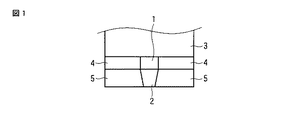
図1は、第1の実施形態に係る磁気記録ヘッドを媒体対向面から見た図である。主磁極2とリターンヨーク3との間にスピントルク発振子(STO)1が位置する。主磁極2の周囲には非磁性金属層5が設けられている。スピントルク発振子1の周囲には絶縁層4が設けられている。
<First Embodiment>
FIG. 1 is a diagram of the magnetic recording head according to the first embodiment viewed from the medium facing surface. A spin torque oscillator (STO) 1 is located between the main
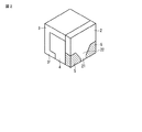
図2は、第1の実施形態に係る磁気記録ヘッドを示す斜視図である。図2において磁気記録ヘッドの底面が媒体対向面となる。主磁極2とリターンヨーク3とが対向しており、その間に絶縁層4が設けられている。主磁極2は、媒体対向面側において絞り込み部22および先端部21を有している。絞り込み部22および先端部21の周囲には非磁性金属層5が設けられている。リターンヨーク3は、媒体対向面において主磁極2に向けて突出した突出部31を有する。なお、図2に示した磁気記録ヘッドでは、コイルが省略されている。
FIG. 2 is a perspective view showing the magnetic recording head according to the first embodiment. In FIG. 2, the bottom surface of the magnetic recording head is the medium facing surface. The main
非磁性金属層5は、図1および2に示されるように、絞り込み部22および先端部21の左右に設けられている。そのため、主磁極2は、非磁性金属層5とともに1つの平板上の構造を形成している。主磁極2および非磁性金属層5は、スピントルク発振子1に電流を流す際、一体となって電極として機能する。図1に示されるように、主磁極2および非磁性金属層5の媒体対向面の面積は、スピントルク発振子1の媒体対向面の面積よりも大きい。これによって、スピントルク発振子1に流れる電流が均一化される。さらに、非磁性金属層5は、熱拡散を助けるヒートシンクとして機能するため、スピントルク発振子1の過熱が抑制される。また、電流の駆動効率が上がるため、より発振層の磁気体積(Mst:nmT)が大きいスピントルク発振子1を駆動することが出来るようになる。なお、冷却効果は、スピントルク発振子1に対して非磁性金属層5が大きくなるほど向上する。例えば、主磁極2および非磁性金属層5の媒体対向面の面積を、スピントルク発振子1の媒体対向面の面積の100倍程度とすることができる。非磁性金属層5の材料としては、Ru、Ta、Au、AgおよびCuから成る群から選択される金属の少なくとも一つを含む合金を使用することができる。
As shown in FIGS. 1 and 2, the
図1および2に示されるように、絶縁層4は、主磁極2および非磁性発振層5と、リターンヨーク3との間であって、スピントルク発振子1の周囲およびコイル(図示せず)の周囲に設けられる。絶縁層4は、主磁極2とリターンヨーク3との間の、意図しない電流の通過を防止する。絶縁層4の材料としては、例えば、SiO2、アルミナ等を使用することができる。
As shown in FIGS. 1 and 2, the
スピントルク発振子1は、図1に示されるように、主磁極2とリターンヨーク3との間に配置される。より高い高周波アシスト効果を得るために、スピントルク発振子1をABS面付近に配置することが好ましい。スピントルク発振子1は、複数の層が積層した構造となっている。この複数の層には、少なくとも発振層およびスピン注入層が含まれる。発振層とスピン注入層との間に中間層を設けることもできる。さらに、その他の発振の制御のための層を設けることもできる。スピントルク発振子1を積層する向きについては特に限定はなく、主磁極1側に発振層を配置し、リターンヨーク3側にスピン注入層を配置させてよく、またはその逆の配置にしてもよい。スピントルク発振子1の最も外側の層に対して、金属の上部層および下地層を形成し、それらの層を介して主磁極2およびリターンヨーク3に電気的に接続することもできる。また、スピントルク発振子1は、例えば10−100nm角の大きさに形成される。
As shown in FIG. 1, the
発振層は、主磁極2とリターンヨーク3との間に電流を流した際、スピントルクにより発振する。このとき発振周波数は、主磁極2とリターンヨーク3との間に発生するギャップ磁界が大きいほど高周波数となる。発振層は、主として、高Bs軟磁性材料により形成される。スピン注入層は、垂直磁気異方性を持つ金属磁性体で形成される。発振層は、具体的には、Fe、CoおよびNiから選択される磁性元素の合金とすることができる。また、Fe、CoおよびNi等の合金に非磁性元素を添加したものを使用してもよい。非磁性元素が添加されている発振層の材料としては、FeCoMnSi、FeCoAlSi等のホイスラー合金を用いることが出来る。ホイスラー合金はスピン分極率が非常に高く、スピントルク発振の駆動電流を低減するのに有効である。発振層は2層以上の磁性層から構成されていてもよい。具体的には、ホイスラー合金を中間層側界面に形成し、さらにFeCo合金を中間層とは反対側に形成することで、十分な磁気体積と良好なスピントルク駆動電圧の低減を両立できる。スピン注入層は、例えば、具体的にはCoPt合金、CoPd合金、Co/Pt人工格子、Co/Pd人工格子、Co/Ni人工格子、Co/Fe人工格子等を用いて形成される。また、スピン注入層は、垂直磁気異方性膜のみで形成されていなくてもよい。具体的には、最終的に垂直磁気異方性が保たれる範囲内であれば、軟磁性層との積層により構成されてもよい。前記垂直磁気異方性膜はスピン分極率の点では、軟磁性FeCo合金や、ホイスラー合金と比べて不利であるため、スピン注入層の中間層側界面に軟磁性FeCo合金や、ホイスラー合金を形成することで、垂直磁気方性と良好なスピントルク駆動電圧の低減を両立できる。中間層は、主としてスピン透過率の高い非磁性材料によって形成され、例えばCu、AuまたはAg等が用いられる。
The oscillation layer oscillates by spin torque when a current is passed between the main
主磁極2は、データトラック幅に応じた領域に磁界を集中できるように、データトラック幅程度の幅にパターニングされる。すなわち、主磁極2は、媒体対向面側において、先端部21と絞り込み部22とを有する。主磁極2は、磁気記録媒体を磁化させるための磁極として機能し、同時に、スピントルク発振子1に電流を供給するための電極としても機能する。主磁極2は、主として高透磁率材料から成り、例えば、Fe、CoおよびNiから成る群から選択される金属の合金から成る。
The
リターンヨーク3は、主磁極2に対向して配置される。主磁極2から磁気記録媒体へと向かった磁界を磁気記録ヘッドに戻すことで、磁路を閉じる役割を有する。リターンヨーク3は、同時に、スピントルク発振子1に電流を供給するための電極としても機能する。
The
図2に示されるように、リターンヨーク3の媒体対向面において、主磁極に向けて突出する突出部31を設けることができる。一方、図3に示されるように、リターンヨーク3と主磁極2と対向する面同士を平行にすることもできる(図3は、媒体対向面および主磁極2に対してそれぞれ垂直な、先端部21を通る平面で切断した断面図である)。リターンヨーク3に突出部31を設けない場合、主磁極2を出た記録磁界がリターンヨーク3に戻る傾向が高まる一方、主磁極2を出る記録磁界が磁気記録媒体を通過せずにリターンヨーク3方向に向かう傾向も高まる。その結果、高い記録磁界強度を得ることができる一方、記録磁界が磁気記録媒体へ向かう際のシャープさが低下する。これに対し、リターンヨーク3に突出部31を設けた場合、記録磁界がリターンヨーク3に戻る傾向は弱まるが、主磁極2からリターンヨーク3へと直接向かう磁界を低減することができる。その結果、一定の記録磁界強度を維持しつつ、記録磁界のシャープさを向上することができる。
As shown in FIG. 2, a
図2では、主磁極2とリターンヨーク3とが、磁気記録ヘッドの上部において直接接触するように示されている。しかしながら、主磁極2とリターンヨーク3とは直接接触しなくてもよい。この接触は、高周波発振のための電流を流すときの、電流の通路に関与する。すなわち、主磁極2およびリターンヨーク3は、スピントルク発振子1に電流を流すための電極として機能するが、直接接触させた場合、電流は、その接触した部分とスピントルク発振子1とを流れる。一方、接触させない場合、電流は、スピントルク発振子1のみを流れる。何れの場合であっても、電流がスピントルク発振子1を通過する構造をとる必要がある。
In FIG. 2, the main
磁気記録ヘッドはコイルを有する。コイルは、主磁極2およびリターンヨーク3を通る磁路の一部に巻きつけられる。コイルに対して記録磁界発生用電源から電流が供給されると、主磁極2、リターンヨーク3および磁気記録媒体を通る磁界が生じる。コイルとしては導電性の高い金属材料を用いることができる。
The magnetic recording head has a coil. The coil is wound around a part of a magnetic path passing through the main
主磁極2およびリターンヨーク3との間において、スピントルク発振子1の他に任意の構造を設けることができる。例えば、スピントルク発振子1と主磁極2またはリターンヨーク3との間に、電極を設けることができる。この電極の材料としては、主として電気抵抗が低く酸化されにくい材料を用いることができ、例えばTiまたはCu等を使用することができる。また、スピントルク発振子1に流れる電流を整えるための、何らかの積層構造を設けることもできる。
In addition to the
<第2の実施形態>
次に、第2の実施形態に係る磁気記録ヘッドを説明する。第1の実施形態に係る磁気記録ヘッドとの差異は、主磁極2の絞り込み部22および先端部21の周囲に非磁性金属層5が設けられないこと、及びリターンヨーク3側に第2の非磁性金属層6が設けられることである。第2の実施形態に係る磁気記録ヘッドでは、非磁性金属層5の代わりに例えば絶縁層が設けられる。
<Second Embodiment>
Next, a magnetic recording head according to the second embodiment will be described. The difference from the magnetic recording head according to the first embodiment is that the
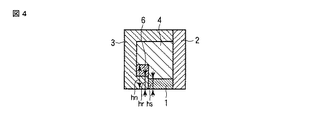
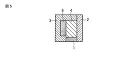
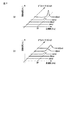
図4および5は、第2の実施形態に係る磁気記録ヘッドの断面図を示す。当該断面図は、媒体対向面および主磁極2に対してそれぞれ垂直な、先端部21を通る平面で切断した図である。したがって、図1または2に示される磁気記録ヘッドの非磁性金属層5に対応する位置は、図4および5において示されていない。第2の実施形態に係る磁気記録ヘッドでは、リターンヨーク3が、媒体対向面に、主磁極に向けて突出した突出部31を有する。この突出部31上に第2の非磁性金属層6が設けられている。図4では、第2の非磁性金属層6が突出部31上に設けられているが、リターンヨーク3の上部まで達していない。一方、図5では、第2の非磁性金属層6が、リターンヨーク3の上部まで達している。スピントルク発振子1に電流を流す際、リターンヨーク3と第2の非磁性金属層6とは、一体となって電極として機能する。第2の非磁性金属層6は、熱拡散を助けるヒートシンクとしても機能し、スピントルク発振子1の過熱を抑制する。
4 and 5 are sectional views of the magnetic recording head according to the second embodiment. The cross-sectional view is a view cut along a plane passing through the
図4および5に示されるように、第2の実施形態に係る磁気記録ヘッドにおいて、突出部31の媒体対向面からの高さ(図4中hrで示される長さ)は、スピントルク発振子1の媒体対向面からの高さ(図4中hsで示される長さ)よりも長いことが好ましい。hsを小さくすることで記録磁界強度を高めることができる。しかし、hsを小さくしすぎた場合、スピントルク発振子1の発振のための磁界が低下および不均一化して、発振周波数が十分に高くならず、スピントルク効率が低下する。そのため、スピントルク発振子1を適切な高さに維持し、リターンヨーク3の突出部31をそれよりも高くすることが望ましい。
As shown in FIGS. 4 and 5, in the magnetic recording head according to the second embodiment, the height of the
図4および5に示されるように、リターンヨーク3および第2の非磁性金属層6から成る電極は、スピントルク発振子1に対して十分に大きいことが好ましい。このことは、例えば、第2の非磁性金属層6の媒体対向面からの高さ(図4中hnで示される長さ)を、スピントルク発振子1の媒体対向面からの高さ(すなわちhs)の10倍以上にすることで達成できる。hnがhsに対して十分大きい場合、スピントルク発振子1に流れる電流をより均等にすることができる。一方、hnが小さい場合、高さ方向からスピントルク発振子1に流入する電流が、媒体対向面に水平な方向から流入する電流よりも相対的に小さくなり、結果として、流入する電流が偏流して、スピントルク効率が低下する。
As shown in FIGS. 4 and 5, the electrode composed of the
第2の非磁性金属層6としては、非磁性金属層5と同様の材料を使用することができる。第2の実施形態に係る磁気記録ヘッドにおいて、スピントルク発振子1、主磁極2、絶縁層4およびコイルは、第1の実施形態に係る磁気記録ヘッドと共通するものを使用することができる。一方、第2の実施形態に係る磁気記録ヘッドにおいて、リターンヨーク3は突出部31を有する必要がある。但し、リターンヨーク3の記録磁界の発生における機能、および材料は、第1の実施形態に係る磁気記録ヘッドと共通する。
As the second
<第3の実施形態>
次に、第3の実施形態に係る磁気記録ヘッドを説明する。第3の実施形態に係る磁気記録ヘッドでは、主磁極2の絞り込み部22および先端部21の周囲に非磁性金属層5が設けられており、且つリターンヨーク3に突出部31が設けられ、その上に第2の非磁性金属層6が設けられている。
<Third Embodiment>
Next, a magnetic recording head according to the third embodiment will be described. In the magnetic recording head according to the third embodiment, the
第3の実施形態に係る磁気記録ヘッドにおいて、スピントルク発振子1、主磁極2、絶縁層4、非磁性金属層5、第2の非磁性金属層6およびコイルは、第1および2の実施形態に係る磁気記録ヘッドと共通する。リターンヨーク3は、第2の実施形態に係る磁気記録ヘッドと共通する。
In the magnetic recording head according to the third embodiment, the
<磁気記録媒体について>
実施形態に係る磁気記録装置において使用される磁気記録媒体に特別な限定はなく、任意のものを使用できる。例えば、下から基板、軟磁性層、非磁性層、記録層および保護膜層が順に積層された磁気記録媒体を使用することができる。この場合、良好な垂直磁気記録が達成できる。また、特に記録層を面方向に特定のパターンを形成したパターンドメディア(DTR媒体、BPM等)を使用することもできる。
<About magnetic recording media>
There is no particular limitation on the magnetic recording medium used in the magnetic recording apparatus according to the embodiment, and an arbitrary one can be used. For example, a magnetic recording medium in which a substrate, a soft magnetic layer, a nonmagnetic layer, a recording layer, and a protective film layer are sequentially laminated from the bottom can be used. In this case, good perpendicular magnetic recording can be achieved. In particular, patterned media (DTR media, BPM, etc.) in which a specific pattern is formed in the surface direction of the recording layer can also be used.
<磁気記録装置について>
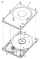
図6は、実施形態に係る磁気記録ヘッドを搭載した磁気記録装置150を示す斜視図である。
<About magnetic recording devices>
FIG. 6 is a perspective view showing a
図6に示すように、磁気記録装置150は、ロータリーアクチュエータを用いた形式の装置である。磁気記録媒体200は、スピンドルモータ140に装着され、図示しない駆動装置制御部からの制御信号に応答する図示しないモータにより矢印Aの方向に回転する。磁気記録装置150は、複数の磁気記録媒体200を備えたものでもよい。
As shown in FIG. 6, the
磁気記録媒体200に対して情報の記録再生を行うヘッドスライダー130は、薄膜状のサスペンション154の先端に取り付けられている。ヘッドスライダー130の先端付近には実施形態に係る磁気記録ヘッドが設けられている。磁気記録媒体200が回転すると、サスペンション154による押付け圧力とヘッドスライダー130の媒体対向面(ABS)で発生する圧力とがつりあい、ヘッドスライダー130の媒体対向面は、磁気記録媒体200の表面から所定の浮上量をもって保持される。
A
サスペンション154は、図示しない駆動コイルを保持するボビン部などを有するアクチュエータアーム155の一端に接続されている。アクチュエータアーム155の他端には、リニアモータの一種であるボイスコイルモータ156が設けられている。ボイスコイルモータ156は、アクチュエータアーム155のボビン部に巻き上げられた図示しない駆動コイルと、このコイルを挟み込むように対向して配置された永久磁石及び対向ヨークからなる磁気回路とから構成することができる。アクチュエータアーム155は、ピボット157の上下2箇所に設けられた図示しないボールベアリングによって保持され、ボイスコイルモータ156により回転摺動が自在にできるようになっている。その結果、磁気ヘッドを磁気記録媒体200の任意の位置にアクセスできる。
The
(実施例1)
第1の実施形態に係る磁気記録ヘッド(実施例1)および従来の磁気記録ヘッド(比較例)を作製し、それぞれの発振強度を比較した。
Example 1
A magnetic recording head according to the first embodiment (Example 1) and a conventional magnetic recording head (Comparative Example) were produced, and their oscillation intensities were compared.
実施例1を次の通りに作製した。基板上にFeCo合金を成膜した後、パターニングによって先端部21および絞り込み部22を有した主磁極2を形成した。先端部21の幅は50nmとした。次に、主磁極2の上に、非磁性金属層5の材料としてのRuを成膜し、その後主磁極3が露出するまでエッチバックした。これによって、先端部21および絞り込み部22の周囲にRuが埋め込まれた主磁極側一体電極を形成した。Ruの埋め込みの範囲は、先端部21を下にしたとき、横方向に10μm、高さ方向に2μmであった。その後、先端部21上にスピントルク発振子1[5Ta/5Cu/(0.2Co/0.6Ni)15/2Cu/12FeCo/1Cu/3Ta/10Ru(数字はnm)]を50nm角の形状に形成した。さらに、その上からSiO2を成膜した。その後、hrが150nmである突出部31を有したリターンヨーク3およびコイルを形成した。
Example 1 was made as follows. After forming a FeCo alloy film on the substrate, the main
比較例は、主磁極2の先端部21および絞り込み部22の周囲に、Ruの代わりにアルミナ絶縁体を設けたこと以外は、上記製造方法と同様に製造した。
The comparative example was manufactured in the same manner as in the above manufacturing method except that an alumina insulator was provided around the
このように作製した2種の磁気記録ヘッドにおいて、コイルに40ミリアンペアの電流を流し、主磁極2に記録磁界を誘起した状態で、スピントルク発振子1にバイアス電圧をかけて発振挙動を測定した。その結果を図7に示す。図7aおよび図7bは、それぞれ実施例1および比較例の結果である。実施例1では、バイアス電圧を上げるに従い、発振強度が増大し、20GHz近傍にシャープなピークを発生させることができた。一方、比較例では、実施例1と比較してピークがブロードで且つ強度の低い発振が得られた。実施例1において80mVのバイアス電圧でシャープな発振が得られたに対して、比較例では、120mVのバイアス電圧を印加してもブロードで低い値であった。
In the two types of magnetic recording heads thus fabricated, the oscillation behavior was measured by applying a bias voltage to the
(実施例2)
第2の実施形態に係る磁気記録ヘッド(実施例2)を作製し、比較例との間で発振強度を比較した。
(Example 2)
A magnetic recording head (Example 2) according to the second embodiment was manufactured, and the oscillation intensity was compared with the comparative example.
基板上にFeCo合金を成膜した後、パターニングによって先端部21および絞り込み部22を有した主磁極2を形成した。先端部21の幅は50nmとした。次に、主磁極2の上に、アルミナ絶縁体を成膜し、その後主磁極3が露出するまでエッチバックした。その後、先端部21上にスピントルク発振子1[5Ta/5Cu/(0.2Co/0.6Ni)15/2Cu/12FeCo/1Cu/3Ta/10Ru(数字はnm)]を50nm角の形状に形成した。さらに、その上からSiO2を成膜した。その後、hrが200nmである突出部31を有したリターンヨーク3、第2の非磁性金属層およびコイルを形成した。第2の非磁性金属層はhnが1μmとなるように形成した。
After forming a FeCo alloy film on the substrate, the main
このように作製した磁気記録ヘッドにおいて、コイルに40ミリアンペアの電流を流し、主磁極に記録磁界を誘起した状態で、STOにバイアス電圧をかけて発振挙動を測定した。その結果、実施例1と同様に、比較例と比較して、ピークがシャープで、且つ強度の高い発振が得られた。 In the magnetic recording head manufactured as described above, the oscillation behavior was measured by applying a bias voltage to the STO in a state where a current of 40 mA was passed through the coil and a recording magnetic field was induced in the main magnetic pole. As a result, as in Example 1, an oscillation with a sharper peak and higher intensity was obtained as compared with the comparative example.
(実施例3)
第3の実施形態に係る磁気記録ヘッド(実施例3)を作製し、比較例との間で発振強度を比較した。
(Example 3)
A magnetic recording head (Example 3) according to the third embodiment was manufactured, and the oscillation intensity was compared with the comparative example.
主磁極2の先端部21および絞り込み部22の周囲に設ける材料として、非磁性金属層5としてのRuを使用したこと以外は、実施例2と同様に作製した。
It was produced in the same manner as in Example 2 except that Ru as the
このように作製した磁気記録ヘッドにおいて、コイルに40ミリアンペアの電流を流し、主磁極に記録磁界を誘起した状態で、STOにバイアス電圧をかけて発振挙動を測定した。その結果、実施例1と同様に、比較例と比較して、ピークがシャープで、且つ強度の高い発振が得られた。 In the magnetic recording head manufactured as described above, the oscillation behavior was measured by applying a bias voltage to the STO in a state where a current of 40 mA was passed through the coil and a recording magnetic field was induced in the main magnetic pole. As a result, as in Example 1, an oscillation with a sharper peak and higher intensity was obtained as compared with the comparative example.
本発明のいくつかの実施形態を説明したが、これらの実施形態は、例として提示したものであり、発明の範囲を限定することは意図していない。これら新規な実施形態は、その他の様々な形態で実施されることが可能であり、発明の要旨を逸脱しない範囲で、種々の省略、置き換え、変更を行うことができる。これら実施形態やその変形は、発明の範囲や要旨に含まれるとともに、特許請求の範囲に記載された発明とその均等の範囲に含まれる。 Although several embodiments of the present invention have been described, these embodiments are presented by way of example and are not intended to limit the scope of the invention. These novel embodiments can be implemented in various other forms, and various omissions, replacements, and changes can be made without departing from the scope of the invention. These embodiments and modifications thereof are included in the scope and gist of the invention, and are included in the invention described in the claims and the equivalents thereof.
1…スピントルク発振子、2…主磁極、21…先端部、22…絞り込み部、3…リターンヨーク、31…突出部、4…絶縁層、5…非磁性金属層、6…第2の非磁性金属層、130…ヘッドスライダー、140…スピンドルモータ、150…磁気記録装置、154…サスペンション、155…アクチュエータアーム、156…ボイスコイルモータ、157…ピボット、200…磁気記録媒体。
DESCRIPTION OF
Claims (4)
前記主磁極と対を成すリターンヨークと、
前記主磁極と前記リターンヨークとの間に設けられたスピントルク発振子と、
前記主磁極の絞り込み部および先端部の周囲に設けられた非磁性金属層と、
前記主磁極と前記リターン磁極との間で、前記スピントルク発振子の周囲に設けられた絶縁層と
を有する磁気記録ヘッド。 A main magnetic pole for generating a recording magnetic field in the magnetic recording medium, the main magnetic pole having a narrowed portion and a tip portion;
A return yoke paired with the main pole;
A spin torque oscillator provided between the main pole and the return yoke;
A nonmagnetic metal layer provided around the narrowed portion and the tip of the main pole;
A magnetic recording head having an insulating layer provided around the spin torque oscillator between the main magnetic pole and the return magnetic pole.
前記主磁極と対を成し、媒体対向面に、前記主磁極に向けて突出した突出部を有するリターンヨークと、
前記主磁極と前記リターンヨークとの間に設けられたスピントルク発振子と、
前記突出部上に設けられた第2の非磁性金属層と、
前記主磁極と前記リターン磁極との間で、前記スピントルク発振子の周囲に設けられた絶縁層と
を有する磁気記録ヘッド。 A main pole for generating a recording magnetic field in the magnetic recording medium;
A return yoke that forms a pair with the main magnetic pole, and has a protruding portion that protrudes toward the main magnetic pole on the medium facing surface;
A spin torque oscillator provided between the main pole and the return yoke;
A second nonmagnetic metal layer provided on the protruding portion;
A magnetic recording head having an insulating layer provided around the spin torque oscillator between the main magnetic pole and the return magnetic pole.
Priority Applications (1)
| Application Number | Priority Date | Filing Date | Title |
|---|---|---|---|
| JP2010150351A JP2012014792A (en) | 2010-06-30 | 2010-06-30 | Magnetic recording head and magnetic recording device |
Applications Claiming Priority (1)
| Application Number | Priority Date | Filing Date | Title |
|---|---|---|---|
| JP2010150351A JP2012014792A (en) | 2010-06-30 | 2010-06-30 | Magnetic recording head and magnetic recording device |
Publications (1)
| Publication Number | Publication Date |
|---|---|
| JP2012014792A true JP2012014792A (en) | 2012-01-19 |
Family
ID=45601030
Family Applications (1)
| Application Number | Title | Priority Date | Filing Date |
|---|---|---|---|
| JP2010150351A Pending JP2012014792A (en) | 2010-06-30 | 2010-06-30 | Magnetic recording head and magnetic recording device |
Country Status (1)
| Country | Link |
|---|---|
| JP (1) | JP2012014792A (en) |
Cited By (13)
| Publication number | Priority date | Publication date | Assignee | Title |
|---|---|---|---|---|
| JP2013246851A (en) * | 2012-05-25 | 2013-12-09 | Toshiba Corp | Method for manufacturing magnetic recording head |
| JP2014116036A (en) * | 2012-12-06 | 2014-06-26 | Toshiba Corp | Magnetic head, magnetic head assembly and magnetic recording/reproducing apparatus |
| US8837088B1 (en) | 2013-09-19 | 2014-09-16 | HGST Netherlands B.V. | Microwave-assisted magnetic recording (MAMR) head with a current confinement structure |
| JP2015043247A (en) * | 2013-08-26 | 2015-03-05 | 株式会社東芝 | Magnetic recording head and magnetic recording / reproducing apparatus using the same |
| US10403308B2 (en) | 2017-08-10 | 2019-09-03 | Kabushiki Kaisha Toshiba | Magnetic disk device which controls a recording operation and a non-recording operation of a recording head and a recording head control method of the magnetic disk device |
| US10504543B1 (en) | 2018-08-24 | 2019-12-10 | Kabushiki Kaisha Toshiba | Magnetic disk device |
| US10546600B1 (en) | 2018-08-24 | 2020-01-28 | Kabushiki Kaisha Toshiba | Magnetic head with high-frequency oscillating element and disk device comprising the same |
| US10741201B2 (en) | 2018-12-28 | 2020-08-11 | Kabushiki Kaisha Toshiba | Magnetic recording device capable of stabilizing oscillations of high frequency assisted element |
| US10825473B2 (en) | 2018-08-24 | 2020-11-03 | Kabushiki Kaisha Toshiba | Magnetic disk device |
| US11404084B2 (en) | 2020-09-17 | 2022-08-02 | Kabushiki Kaisha Toshiba | Magnetic disk device |
| US11626132B2 (en) | 2021-06-15 | 2023-04-11 | Kabushiki Kaisha Toshiba | Magnetic disk device |
| US11817135B2 (en) | 2022-02-01 | 2023-11-14 | Kabushiki Kaisha Toshiba | Magnetic head and magnetic recording/reproducing device |
| US12027187B2 (en) | 2022-09-22 | 2024-07-02 | Kabushiki Kaisha Toshiba | Magnetic disk device |
Citations (3)
| Publication number | Priority date | Publication date | Assignee | Title |
|---|---|---|---|---|
| JP2001006130A (en) * | 1999-06-24 | 2001-01-12 | Tdk Corp | Tunneling magneto-resistance effect type head |
| JP2006018985A (en) * | 2004-07-01 | 2006-01-19 | Headway Technologies Inc | Magnetic head for perpendicular magnetic recording, and manufacturing method thereof |
| JP2010079976A (en) * | 2008-09-25 | 2010-04-08 | Toshiba Corp | Magnetic recording head and magnetic recording device |
-
2010
- 2010-06-30 JP JP2010150351A patent/JP2012014792A/en active Pending
Patent Citations (3)
| Publication number | Priority date | Publication date | Assignee | Title |
|---|---|---|---|---|
| JP2001006130A (en) * | 1999-06-24 | 2001-01-12 | Tdk Corp | Tunneling magneto-resistance effect type head |
| JP2006018985A (en) * | 2004-07-01 | 2006-01-19 | Headway Technologies Inc | Magnetic head for perpendicular magnetic recording, and manufacturing method thereof |
| JP2010079976A (en) * | 2008-09-25 | 2010-04-08 | Toshiba Corp | Magnetic recording head and magnetic recording device |
Cited By (14)
| Publication number | Priority date | Publication date | Assignee | Title |
|---|---|---|---|---|
| JP2013246851A (en) * | 2012-05-25 | 2013-12-09 | Toshiba Corp | Method for manufacturing magnetic recording head |
| JP2014116036A (en) * | 2012-12-06 | 2014-06-26 | Toshiba Corp | Magnetic head, magnetic head assembly and magnetic recording/reproducing apparatus |
| JP2015043247A (en) * | 2013-08-26 | 2015-03-05 | 株式会社東芝 | Magnetic recording head and magnetic recording / reproducing apparatus using the same |
| CN104424958A (en) * | 2013-08-26 | 2015-03-18 | 株式会社东芝 | Magnetic recording head and magnetic recording/reproducing apparatus using the same |
| US8837088B1 (en) | 2013-09-19 | 2014-09-16 | HGST Netherlands B.V. | Microwave-assisted magnetic recording (MAMR) head with a current confinement structure |
| US10403308B2 (en) | 2017-08-10 | 2019-09-03 | Kabushiki Kaisha Toshiba | Magnetic disk device which controls a recording operation and a non-recording operation of a recording head and a recording head control method of the magnetic disk device |
| US10504543B1 (en) | 2018-08-24 | 2019-12-10 | Kabushiki Kaisha Toshiba | Magnetic disk device |
| US10546600B1 (en) | 2018-08-24 | 2020-01-28 | Kabushiki Kaisha Toshiba | Magnetic head with high-frequency oscillating element and disk device comprising the same |
| US10825473B2 (en) | 2018-08-24 | 2020-11-03 | Kabushiki Kaisha Toshiba | Magnetic disk device |
| US10741201B2 (en) | 2018-12-28 | 2020-08-11 | Kabushiki Kaisha Toshiba | Magnetic recording device capable of stabilizing oscillations of high frequency assisted element |
| US11404084B2 (en) | 2020-09-17 | 2022-08-02 | Kabushiki Kaisha Toshiba | Magnetic disk device |
| US11626132B2 (en) | 2021-06-15 | 2023-04-11 | Kabushiki Kaisha Toshiba | Magnetic disk device |
| US11817135B2 (en) | 2022-02-01 | 2023-11-14 | Kabushiki Kaisha Toshiba | Magnetic head and magnetic recording/reproducing device |
| US12027187B2 (en) | 2022-09-22 | 2024-07-02 | Kabushiki Kaisha Toshiba | Magnetic disk device |
Similar Documents
| Publication | Publication Date | Title |
|---|---|---|
| JP2012014792A (en) | Magnetic recording head and magnetic recording device | |
| US10438616B2 (en) | Magnetic recording head with specified thickness and saturation magnetic flux density products for STO magnetic layers | |
| JP6495841B2 (en) | Magnetic recording head and magnetic recording / reproducing apparatus | |
| US10236021B2 (en) | Magnetic recording apparatus having magnetic flux control part and magnetic recording head having magnetic flux control part | |
| JP5361259B2 (en) | Spin torque oscillator, magnetic recording head, magnetic head assembly, and magnetic recording apparatus | |
| JP5319746B2 (en) | Magnetic recording head and disk device provided with the same | |
| JP4951095B2 (en) | Magnetic recording head and magnetic recording apparatus | |
| JP5117606B1 (en) | Magnetic recording head, manufacturing method thereof, and magnetic disk apparatus | |
| JP5039223B1 (en) | Magnetic head, head gimbal assembly including the same, and disk drive | |
| JP2019057338A (en) | Magnetic head and magnetic recording / reproducing apparatus | |
| JP5902037B2 (en) | Magnetic recording head, magnetic head assembly, and magnetic recording / reproducing apparatus | |
| JP2013251042A (en) | Spin torque oscillator, magnetic recording head, magnetic head assembly, and magnetic recorder | |
| US20120002331A1 (en) | Magnetic recording head and magnetic recording apparatus | |
| CN105321530A (en) | Microwave assisted magnetic recording head and magnetic recording device having the same | |
| US20130148242A1 (en) | Magnetic recording head and disk drive with the same | |
| JP2015043247A (en) | Magnetic recording head and magnetic recording / reproducing apparatus using the same | |
| JP7319603B2 (en) | Magnetic head and magnetic recording device | |
| US9792930B1 (en) | Microwave-assisted magnetic recording head and magnetic recording and reproducing device | |
| JP2008287790A (en) | Perpendicular magnetic recording head | |
| JP2012014783A (en) | Magnetic recording head and magnetic recording device | |
| JP2007335062A (en) | Thin film magnetic head | |
| JP2007220180A (en) | Thin film magnetic head | |
| JP6586251B2 (en) | Magnetic recording head and magnetic recording / reproducing apparatus | |
| JP2019200835A (en) | Magnetic recording head and magnetic recording/reproducing device | |
| US20260065928A1 (en) | Magnetic recording device |
Legal Events
| Date | Code | Title | Description |
|---|---|---|---|
| A02 | Decision of refusal |
Free format text: JAPANESE INTERMEDIATE CODE: A02 Effective date: 20120207 |