JP2012013180A - Valve control apparatus - Google Patents
Valve control apparatus Download PDFInfo
- Publication number
- JP2012013180A JP2012013180A JP2010151833A JP2010151833A JP2012013180A JP 2012013180 A JP2012013180 A JP 2012013180A JP 2010151833 A JP2010151833 A JP 2010151833A JP 2010151833 A JP2010151833 A JP 2010151833A JP 2012013180 A JP2012013180 A JP 2012013180A
- Authority
- JP
- Japan
- Prior art keywords
- rod
- valve
- point
- lever
- control device
- Prior art date
- Legal status (The legal status is an assumption and is not a legal conclusion. Google has not performed a legal analysis and makes no representation as to the accuracy of the status listed.)
- Granted
Links
Images


Classifications
-
- Y—GENERAL TAGGING OF NEW TECHNOLOGICAL DEVELOPMENTS; GENERAL TAGGING OF CROSS-SECTIONAL TECHNOLOGIES SPANNING OVER SEVERAL SECTIONS OF THE IPC; TECHNICAL SUBJECTS COVERED BY FORMER USPC CROSS-REFERENCE ART COLLECTIONS [XRACs] AND DIGESTS
- Y02—TECHNOLOGIES OR APPLICATIONS FOR MITIGATION OR ADAPTATION AGAINST CLIMATE CHANGE
- Y02T—CLIMATE CHANGE MITIGATION TECHNOLOGIES RELATED TO TRANSPORTATION
- Y02T10/00—Road transport of goods or passengers
- Y02T10/10—Internal combustion engine [ICE] based vehicles
- Y02T10/12—Improving ICE efficiencies
Abstract
Description
本発明は、バルブを駆動するロッドをその軸線方向に往復移動させるアクチュエータを備え、ロッドのストローク量に応じてバルブの開閉制御を行うバルブ制御装置に関するもので、特にウェイストゲートバルブの開閉制御を行うバルブ制御装置に係わる。 The present invention relates to a valve control device that includes an actuator that reciprocates a rod that drives a valve in the axial direction thereof, and that controls the opening and closing of the valve in accordance with the stroke amount of the rod. It relates to a valve control device.
[従来の技術]
従来より、ターボチャージャのウェイストゲート流路を開閉するウェイストゲートバルブによる過給圧制御装置が公知である(例えば、特許文献1参照)。
この過給圧制御装置は、図7ないし図9に示したように、ウェイストゲートバルブ101を支持開閉する回転軸102が設置されている。この回転軸102には、リンクレバー103が連結され、このリンクレバー103には、ダイヤフラムアクチュエータ104のロッド105が連結されている。また、ウェイストゲート流路106には、ウェイストゲートバルブ101を着座させるための弁座107が設置されている。
なお、図8の矢印は、リンクレバー103の可動範囲(作動角度)を示す。
[Conventional technology]
Conventionally, a supercharging pressure control device using a wastegate valve that opens and closes a wastegate flow path of a turbocharger is known (see, for example, Patent Document 1).
As shown in FIGS. 7 to 9, the supercharging pressure control device is provided with a rotating
8 indicates the movable range (operation angle) of the
また、ターボチャージャの排気バイパス流路を開閉する排気バイパスバルブを駆動するダイヤフラムアクチュエータが公知である(例えば、特許文献2参照)。
このダイヤフラムアクチュエータ204は、図10ないし図12に示したように、排気バイパスバルブ201を支持開閉する回転軸202が設置されている。この回転軸202には、リンクレバー203が連結され、このリンクレバー203には、ダイヤフラムアクチュエータ204のロッド205が連結されている。また、排気バイパス流路206には、排気バイパスバルブ201を着座させるための弁座207が設置されている。
なお、図11の矢印は、リンクレバー203の可動範囲(作動角度)を示す。
Further, a diaphragm actuator that drives an exhaust bypass valve that opens and closes an exhaust bypass passage of a turbocharger is known (for example, see Patent Document 2).
As shown in FIGS. 10 to 12, the
In addition, the arrow of FIG. 11 shows the movable range (operation angle) of the
[従来の技術の不具合]
ところで、近年、自動車に搭載される内燃機関(エンジン)の排気ガスの規制強化に伴い、排出ガス関係のOBD(車載診断装置による故障診断機能)装着が義務づけされている。
ここで、特許文献1及び2に記載のダイヤフラムアクチュエータ104、204を、ウェイストゲートバルブ101の開閉制御および排気バイパスバルブ201の開閉制御用のアクチュエータとして使用する場合、OBD要件として、ロッド105、205のストローク量を直接検出する必要がある。
そこで、ロッド105、205に、磁石やヨークにより構成される磁気回路を装着し、磁気回路から印加される磁界の磁束密度を磁気センサによって検出して、磁気センサから出力される電気信号に基づいて、ロッド105、205のストローク量を求める方法が考えられる。
[Conventional technical problems]
Incidentally, in recent years, with the tightening of exhaust gas regulations of internal combustion engines (engines) mounted on automobiles, it has become mandatory to install exhaust gas-related OBD (fault diagnosis function using an in-vehicle diagnostic device).
Here, when the
Therefore, a magnetic circuit composed of a magnet and a yoke is attached to the
ところが、特許文献1に記載の過給圧制御装置においては、ウェイストゲートバルブ101の回転軸102とダイヤフラムアクチュエータ104のロッド105とを連結するリンクレバー103の可動範囲が明確ではなく、リンクレバー103が動くとロッド105がその軸線周りに振れる。
具体的には、ウェイストゲートバルブ101が全閉位置(図8(a)参照)から全開位置(図8(b)参照)に至るまでの作動範囲で開閉制御する際、つまりリンクレバー103のロッド105との結合部108が、回転軸102を中心にした所定の曲率半径の曲線である回転軌跡(リンクレバー103の回転作動線)上を移動する際に、ロッド軸振れ量δ分だけロッド105が軸振れする。
これにより、磁気センサを用いてロッド105のストローク量を直接検出する場合、ロッド105の軸振れに伴って検出誤差が大きくなるという問題が生じている。
However, in the supercharging pressure control device described in
Specifically, when the
As a result, when the stroke amount of the
また、特許文献1に記載の過給圧制御装置においては、図9(a)に示したように、ウェイストゲートバルブ101の中間開度よりも全閉側の低開度領域でロッド105の移動量に対する排気ガスの流量の変化率が最も大きく、ウェイストゲートバルブ101の中間開度よりも全開側の高開度領域でロッド105の移動量に対する排気ガスの流量の変化率が小さい。
また、図9(b)に示したように、ウェイストゲートバルブ101の全閉開度から中間開度を経て全開開度に至るまでの全領域でロッド軸振れ量δの変化率が小さい。
これにより、ロッド105の移動量に対する排気ガスの流量の変化率が最も大きい低開度領域において、ロッド105の軸振れ量を小さくして、ロッド105のストローク量の検出精度を向上させる必要がある。
Further, in the supercharging pressure control device described in
Further, as shown in FIG. 9B, the change rate of the rod shaft deflection amount δ is small in the entire region from the fully closed opening of the
Accordingly, it is necessary to improve the detection accuracy of the stroke amount of the
一方、特許文献2に記載のダイヤフラムアクチュエータ204においては、特許文献1に記載のダイヤフラムアクチュエータ104と比べて、図11(a)に示したように、リンクレバー203の回転開始角度が異なるが、特許文献1と同様な問題が生じている。
すなわち、排気バイパスバルブ201が全閉位置(図11(a)参照)から全開位置(図11(b)参照)に至るまでの作動範囲で開閉制御する際に、つまりリンクレバー203のロッド205との結合部208が、回転軸202を中心にした所定の曲率半径の曲線である回転軌跡(リンクレバー103の回転作動線)上を移動する際に、ロッド軸振れ量δ分だけロッド205が軸振れする。
これにより、磁気センサを用いてロッド205のストローク量を直接検出する場合、ロッド205の軸振れに伴って検出誤差が大きくなるという問題が生じている。
On the other hand, in the
That is, when the
As a result, when the stroke amount of the
また、特許文献2に記載のダイヤフラムアクチュエータ204においては、図12(a)に示したように、排気バイパスバルブ201の中間開度よりも全閉側の低開度領域でロッド205の移動量に対する排気ガスの流量の変化率が最も大きく、排気バイパスバルブ201の中間開度よりも全開側の高開度領域でロッド205の移動量に対する排気ガスの流量の変化率が小さい。
また、図12(b)に示したように、排気バイパスバルブ201の全閉開度から中間開度を経て全開開度に至るまでの全領域でロッド軸振れ量δの変化率が小さい。
これにより、ロッド205の移動量に対する排気ガスの流量の変化率が最も大きい低開度領域において、ロッド205の軸振れ量を小さくして、ロッド205のストローク量の検出精度を向上させる必要がある。
Further, in the
Also, as shown in FIG. 12B, the change rate of the rod shaft deflection amount δ is small in the entire region from the fully closed opening of the
Accordingly, it is necessary to improve the detection accuracy of the stroke amount of the
また、特許文献1に記載の過給圧制御装置、および特許文献2に記載のダイヤフラムアクチュエータ204において、ロッド105、205をその軸線方向に摺動自在に支持するロッド軸受を備えている場合には、ロッド105、205の軸振れによってロッド軸受に力が加わり、ロッド105、205がロッド軸受の内周をこじり、ロッド105、205とロッド軸受とが偏摩耗したり、ロッド105、205が作動不能に陥ったりするという問題が生じている。
Further, when the supercharging pressure control device described in
本発明の目的は、アクチュエータのロッドのストローク量を直接検出する際の、ロッドの軸振れによる検出誤差を小さくすることのできるバルブ制御装置を提供することにある。また、ロッドの移動量に対する流量(圧力)の変化率が最も大きい低開度領域でのロッド軸振れ量を最小にすることで、センサの検出精度の向上およびロッドの制御性の向上を図ることのできるバルブ制御装置を提供することにある。 An object of the present invention is to provide a valve control device capable of reducing a detection error due to axial deflection of a rod when directly detecting a stroke amount of a rod of an actuator. Also, by minimizing the amount of rod shaft runout in the low opening range where the rate of change of flow rate (pressure) relative to the amount of rod movement is greatest, the detection accuracy of the sensor and the controllability of the rod are improved. It is an object of the present invention to provide a valve control device that can be used.
請求項1に記載の発明は、アクチュエータのロッドの直線運動をバルブの回転運動に変換するリンク機構のレバーに、バルブの回転中心軸と同一軸心上に回転軸(回転中心)を有し、且つロッドと結合する結合部を有することを特徴としている。
そして、レバーの結合部は、バルブが回転動作する際、レバーの回転軸を中心にした所定の曲率半径の曲線であるレバーの回転作動線上を移動するように構成されている。
そして、バルブが全閉開度となるレバーの回転作動線上の回転作動点が、レバーの回転作動線上の全閉点として設定されている。また、バルブが全開開度となるレバーの回転作動線上の回転作動点が、レバーの回転作動線上の全開点として設定されている。また、バルブが全閉開度と全開開度との中間の開度となるレバーの回転作動線上の回転作動点が、レバーの回転作動線上の中間開度点として設定されている。また、全閉点と全開点とを結ぶ直線から半径方向の外側に向けて最も遠く、しかも全閉点と全開点との間にあるレバーの回転作動線上の回転作動点が、レバーの回転作動線上の振れ幅の端点として設定されている。
以上のようにレバーの回転作動線上の各回転作動点を設定したとき、バルブが回転動作する際、レバーの回転作動線上の振れ幅の端点が、全閉点と中間開度点との間に位置するように設定されている。
In the invention according to
The lever coupling portion is configured to move on a rotation operating line of the lever that is a curve of a predetermined radius of curvature centering on the rotation axis of the lever when the valve rotates.
Then, the rotation operation point on the rotation operation line of the lever where the valve is fully closed is set as the fully closed point on the rotation operation line of the lever. In addition, the rotation operation point on the rotation operation line of the lever where the valve is fully opened is set as the full opening point on the rotation operation line of the lever. Further, the rotation operating point on the rotation operating line of the lever at which the valve has an intermediate opening between the fully closed opening and the full opening is set as an intermediate opening point on the rotation operating line of the lever. In addition, the rotation operation point on the rotation operation line of the lever that is farthest outward in the radial direction from the straight line connecting the fully closed point and the fully open point and between the fully closed point and the fully open point is the rotation operation of the lever. It is set as the end point of the runout width on the line.
As described above, when each rotation operation point on the lever rotation operation line is set, when the valve rotates, the end point of the swing width on the lever rotation operation line is between the fully closed point and the intermediate opening point. It is set to be located.
請求項1に記載の発明によれば、バルブが回転動作する際、レバーの回転作動線上の振れ幅の端点が、全閉点と中間開度点との間に位置するように設定されることにより、ロッド軸振れ量を小さくすることができる。これによって、ロッドのストローク量を直接検出する際におけるロッドの軸振れによる検出誤差を小さくすることができる。
また、レバーの回転作動線上の振れ幅の端点を、全閉点と中間開度点との間に位置させることにより、バルブにおいてロッドの移動量に対する流量(または圧力)の変化率が最も大きい低開度領域でのロッド軸振れ量(レバーの回転角度当たりに対するロッドの軸振れ幅)を最小値に設定できるので、センサによるロッドのストローク量の検出精度の向上およびロッドのストローク量の制御性の向上を図ることができる。
According to the first aspect of the present invention, when the valve rotates, the end point of the swing width on the rotation operating line of the lever is set so as to be located between the fully closed point and the intermediate opening point. As a result, the rod shaft deflection can be reduced. Thereby, it is possible to reduce a detection error due to the axial deflection of the rod when directly detecting the stroke amount of the rod.
In addition, by positioning the end point of the swing width on the rotation operating line of the lever between the fully closed point and the intermediate opening point, the flow rate (or pressure) change rate relative to the amount of movement of the rod in the valve is the smallest. Since the rod shaft runout amount (rod shaft runout width per lever rotation angle) in the opening range can be set to the minimum value, the detection accuracy of the rod stroke amount by the sensor and the controllability of the rod stroke amount are improved. Improvements can be made.
請求項2に記載の発明によれば、バルブとは、内燃機関(エンジン)より流出する排気ガスを制御する排気ガス制御弁の弁体のことである。バルブを、例えば内燃機関(エンジン)に搭載されるターボチャージャのウェイストゲート流路(またはEGRガス流路)を流れる排気ガス(またはEGRガス)の流量を制御する排気ガス流量(またはEGRガス流量)制御弁の弁体に適用しても良い。
請求項3に記載の発明によれば、アクチュエータに、ロッドの軸振れを許容しつつ、ロッドをその軸線方向(ロッド軸方向)に摺動自在に支持するロッド軸受を設置している。そして、バルブが回転動作する際、レバーの回転作動線上の振れ幅の端点が、全閉点と中間開度点との間に位置するように設定されることにより、ロッド軸振れ量を小さくすることができる。これにより、ロッド軸受に大きな力が加わったり、ロッドがロッド軸受の内周をこじったり、ロッドとロッド軸受とが偏摩耗したり、ロッドが作動不能に陥ったりするという不具合の発生を抑えることができる。
According to the second aspect of the present invention, the valve is a valve body of an exhaust gas control valve that controls the exhaust gas flowing out from the internal combustion engine (engine). Exhaust gas flow rate (or EGR gas flow rate) for controlling the flow rate of exhaust gas (or EGR gas) flowing through a wastegate flow path (or EGR gas flow path) of a turbocharger mounted on, for example, an internal combustion engine (engine) You may apply to the valve body of a control valve.
According to the third aspect of the present invention, the actuator is provided with the rod bearing that supports the rod so as to be slidable in the axial direction (rod axial direction) while allowing the shaft to swing. When the valve rotates, the end point of the swing width on the rotation operating line of the lever is set to be located between the fully closed point and the intermediate opening point, thereby reducing the rod shaft swing amount. be able to. As a result, it is possible to suppress the occurrence of problems such as a large force applied to the rod bearing, the rod squeezing the inner periphery of the rod bearing, the rod and the rod bearing are subject to uneven wear, or the rod becomes inoperable. it can.
請求項4に記載の発明によれば、レバーの回転作動線とは、レバーの回転作動線上の全閉点とレバーの回転作動線上の全開点とを、レバーの回転軸(バルブの回転中心軸)を中心にした所定の曲率半径の曲線で結んだ円弧軌跡のことである。
請求項5に記載の発明によれば、レバーの回転作動線上の振れ幅の端点が、全閉点と中間開度点との中央に位置するように設定したことにより、精度が必要な、全閉点から中間開度点までのロッドの振れ幅を最小に設定することができる。
これによって、ロッドのストローク量を直接検出する際におけるロッドの軸振れによる検出誤差を小さくすることができる。また、センサによるロッドのストローク量の検出精度の向上およびロッドのストローク量の制御性の向上を図ることができる。
According to the fourth aspect of the present invention, the rotation operation line of the lever refers to the fully closed point on the rotation operation line of the lever and the full open point on the rotation operation line of the lever. ) Is an arc trajectory connected by a curve of a predetermined radius of curvature centering on).
According to the fifth aspect of the invention, since the end point of the swing width on the rotation operating line of the lever is set to be located at the center between the fully closed point and the intermediate opening point, The swing width of the rod from the closing point to the intermediate opening point can be set to the minimum.
Thereby, it is possible to reduce a detection error due to the axial deflection of the rod when directly detecting the stroke amount of the rod. Further, it is possible to improve the detection accuracy of the rod stroke amount by the sensor and to improve the controllability of the rod stroke amount.
請求項6に記載の発明によれば、アクチュエータは、動力源であるモータの回転を減速する減速機構と、この減速機構の回転運動を前記ロッドの直線運動に変換する変換機構とを備えたことを特徴としている。
請求項7に記載の発明によれば、減速機構は、モータによって回転駆動される駆動ギヤ、およびこの駆動ギヤと噛み合って回転する最終ギヤを有することを特徴としている。
請求項8に記載の発明によれば、変換機構は、バルブの動作パターンに対応した形状のカム溝を有し、減速機構(最終ギヤ)の回転に伴って回転するカムと、カム溝に移動自在に挿入されるフォロワとを備えている。また、ロッドは、フォロワを回転自在に支持する支軸を有し、一端側がフォロワおよび支軸を介してカムに連結し、他端側がバルブに連結することを特徴としている。
According to the invention described in
According to a seventh aspect of the present invention, the speed reduction mechanism has a drive gear that is rotationally driven by a motor, and a final gear that rotates in mesh with the drive gear.
According to the invention described in
請求項9に記載の発明によれば、ロッドの軸線方向への移動量(ストローク量)を検出するストローク検出手段とを備えている。このストローク検出手段は、ロッドに一体的に設置されて、(平行な)一定の磁束密度の磁界を発生する磁石を含む磁性移動体、およびこの磁性移動体のストローク方向への移動に伴って変化する磁束(密度)に対応した電気信号を出力するセンサを有することを特徴としている。
請求項10に記載の発明によれば、センサから出力された電気信号に基づいて、ロッドの直線的なストローク量を検出するストローク検出手段を備えたことを特徴としている。 請求項11に記載の発明によれば、センサは、磁性移動体から印加される磁界の磁束を感磁する感磁面を有することを特徴としている。
According to the ninth aspect of the present invention, the apparatus includes stroke detecting means for detecting a movement amount (stroke amount) of the rod in the axial direction. The stroke detecting means is installed integrally with the rod, and includes a magnet that generates a magnetic field having a constant magnetic flux density (parallel), and changes as the magnetic moving body moves in the stroke direction. It is characterized by having a sensor that outputs an electrical signal corresponding to the magnetic flux (density).
According to the tenth aspect of the present invention, there is provided a stroke detecting means for detecting a linear stroke amount of the rod based on an electric signal output from the sensor. According to an eleventh aspect of the present invention, the sensor has a magnetic sensitive surface that senses the magnetic flux of the magnetic field applied from the magnetic movable body.
以下、本発明の実施の形態を、図面に基づいて詳細に説明する。
本発明は、アクチュエータのロッドのストローク量を直接検出する際の、ロッドの軸振れによる検出誤差を小さくするという目的を、レバーの回転作動線上の振れ幅の端点を、全閉点と中間開度点との間に位置させることで実現した。
また、ロッドの移動量に対する流量(圧力)の変化率が最も大きい低開度領域でのロッド軸振れ量を最小にすることで、センサの検出精度の向上およびロッドの制御性の向上を図るという目的を、レバーの回転作動線上の振れ幅の端点を、全閉点と中間開度点との間に位置させることで実現した。
Hereinafter, embodiments of the present invention will be described in detail with reference to the drawings.
The purpose of the present invention is to reduce the detection error due to the shaft deflection of the rod when directly detecting the stroke amount of the rod of the actuator. Realized by placing it between points.
In addition, by minimizing the amount of rod shaft runout in the low opening range where the rate of change in flow rate (pressure) with respect to the amount of rod movement is the largest, sensor detection accuracy and rod controllability are improved. The purpose was achieved by positioning the end point of the swing width on the rotation operating line of the lever between the fully closed point and the intermediate opening point.
[実施例1の構成]
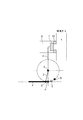
図1ないし図6は本発明の実施例1を示したもので、図1はウェイストゲートバルブの全閉時におけるリンクレバーとロッドとの位置関係を示した図で、図2はウェイストゲートバルブの全開時におけるリンクレバーとロッドとの位置関係を示した図である。
[Configuration of Example 1]
1 to 6
本実施例の内燃機関のウェイストゲートバルブ制御装置は、内燃機関の過給圧制御装置として使用されるシステムであって、内燃機関(エンジン)の排気ガスの流量を制御するウェイストゲートバルブ1と、このウェイストゲートバルブ1のシャフト2に連結するリンクレバー3等のリンク機構と、リンクレバー3を介してウェイストゲートバルブ1に駆動連結するロッド4を有する電動アクチュエータと、内燃機関(エンジン)の運転状況に基づいてウェイストゲートバルブ1の開閉制御を行ってエンジンの過給圧を可変制御するエンジン制御ユニット(ECU)とを備えている。
The waste gate valve control device for an internal combustion engine of the present embodiment is a system used as a supercharging pressure control device for an internal combustion engine, and a
ウェイストゲートバルブ1は、エンジンに搭載されるターボチャージャのウェイストゲート流路9を流れる排気ガスの流量を制御する排気ガス流量制御弁の弁体である。このウェイストゲートバルブ1は、エンジン運転時に、ECUからの制御信号に基づいて、ウェイストゲートバルブ1の全閉位置から全開位置に至るまでのバルブ作動範囲で回転動作されることで、ウェイストゲート流路9の開口面積(排気ガス流通面積)を変更する。
ウェイストゲートバルブ1の背面(隔壁:バルブシートに着座する着座面に対して反対側の端面)には、L字状のシャフト2が一体的に設けられている。
なお、ウェイストゲートバルブ1の詳細は後述する。
The
An L-shaped
Details of the
電動アクチュエータは、ロッド4のストローク方向(荷重作用方向)への移動量(ロッド4のストローク量)に応じてウェイストゲートバルブ1の開閉制御を行う。
電動アクチュエータは、ロッド軸中心線方向(軸線方向)に往復移動するロッド4の他に、ロッド4の揺動(振れ)を許容しつつ、ロッド4をその往復移動方向(ロッド4のストローク方向)に摺動自在に支持するロッド軸受(スラスト軸受)5と、ロッド4に対して、ウェイストゲートバルブ1を閉じる側(バルブ全閉側)に付勢する付勢力(スプリング荷重)を発生するコイルスプリング6と、スラスト軸受5およびコイルスプリング6等の構成部品を収容するアクチュエータケースとを備えている。ここで、電動アクチュエータのロッド4は、そのストローク方向の先端側が、アクチュエータケースの円環状の端面よりアクチュエータケース外部側に突出している。
なお、電動アクチュエータの詳細は、後述する。
The electric actuator performs opening / closing control of the
In addition to the
The details of the electric actuator will be described later.
エンジンは、複数の気筒を有する多気筒ディーゼルエンジンが採用されている。このエンジンの複数(各気筒毎)の吸気ポートには、吸入空気が流れる吸気管が接続されている。この吸気管の途中には、ターボチャージャのコンプレッサ、インタークーラ、スロットルバルブおよびインテークマニホールド等が設置されている。
また、エンジンの複数(各気筒毎)の排気ポートには、排気ガスが流れる排気管が接続されている。この排気管の途中には、エキゾーストマニホールドおよびターボチャージャのタービン等が設置されている。
As the engine, a multi-cylinder diesel engine having a plurality of cylinders is employed. An intake pipe through which intake air flows is connected to a plurality of intake ports (for each cylinder) of the engine. A turbocharger compressor, an intercooler, a throttle valve, an intake manifold, and the like are installed in the middle of the intake pipe.
An exhaust pipe through which exhaust gas flows is connected to a plurality of exhaust ports (for each cylinder) of the engine. In the middle of the exhaust pipe, an exhaust manifold, a turbocharger turbine, and the like are installed.
ターボチャージャは、タービンとコンプレッサとを備え、吸入空気をコンプレッサで圧縮し、圧縮された空気をエンジンの各気筒毎の燃焼室に送り込むターボ過給機である。
タービンは、渦巻形状のタービンハウジング7を備えている。このタービンハウジング7内には、タービンインペラ(タービンホイール)が設置されている。
コンプレッサは、渦巻形状のコンプレッサハウジングを備えている。このコンプレッサハウジング内には、コンプレッサインペラ(コンプレッサホイール)が設置されている。 また、タービンインペラとコンプレッサインペラとは、ロータシャフトによって一体となって回転するように連結されている。
ターボチャージャは、タービンインペラが排気ガスにより回転駆動されると、コンプレッサインペラも回転し、このコンプレッサインペラが吸入空気を圧縮する。
The turbocharger is a turbocharger that includes a turbine and a compressor, compresses intake air by the compressor, and sends the compressed air to a combustion chamber for each cylinder of the engine.
The turbine includes a
The compressor includes a spiral compressor housing. A compressor impeller (compressor wheel) is installed in the compressor housing. Further, the turbine impeller and the compressor impeller are coupled so as to rotate together by a rotor shaft.
In the turbocharger, when the turbine impeller is rotationally driven by the exhaust gas, the compressor impeller also rotates, and the compressor impeller compresses the intake air.
ここで、本実施例のターボチャージャのタービンハウジング7には、ウェイストゲートバルブ1およびウェイストゲート流路9が設けられている。
ウェイストゲート流路9は、タービンハウジング7に導入された排気ガスを、タービンインペラを経由しないで、つまりタービンインペラを迂回(バイパス)してタービンインペラよりも下流側の排気通路へ流すためのバイパス通路(流体通路)である。
あるいはウェイストゲート流路9は、エンジンより流出した排気ガスを、エキゾーストマニホールドの集合部よりも下流側から分岐して、ターボチャージャのタービンよりも排気ガス流方向の下流側で排気通路に合流させる、つまり排気ガスをタービンハウジング7よりバイパスさせるためのバイパス通路(流体通路)である。
Here, a
The
Alternatively, the waste
本実施例のウェイストゲート流路9は、タービンハウジング7の入口部の隔壁で開口した上流側連通孔(ウェイストゲートポート)と、タービンハウジング7の出口部の隔壁で開口した下流側連通孔とを連通する。また、ウェイストゲート流路9には、ウェイストゲートバルブ1を着座させるための弁座(バルブシート)10が設置されている。
ウェイストゲートバルブ1は、例えばステンレス鋼等の金属材料によって円板形状に形成されている。このウェイストゲートバルブ1は、電動アクチュエータのロッド4のロッド軸中心線方向の先端部に接続されて、タービンハウジング7の入口部の隔壁(バルブシート10)に対して着座、離脱して、ウェイストゲート流路9、特にウェイストゲートポートを開閉する排気ガス制御弁である。
The
The
ウェイストゲートバルブ1のシャフト2と電動アクチュエータのロッド4との間には、電動アクチュエータのロッド4の直線運動をウェイストゲートバルブ1の回転運動に変換するリンク機構が設置されている。
このリンク機構は、図1および図2に示したように、一端側が電動アクチュエータのロッド4のストローク方向(往復移動方向)の先端側に連結し、且つ他端側がウェイストゲートバルブ1のシャフト2の先端側(バルブ側に対して反対側)に連結したリンクレバー3等を有している。
ここで、ロッド4のストローク方向の先端側には、ロッド4の裏面側から打ち込まれて表面側に突出した第1ヒンジピン(第1支持軸)11が固定(または一体的に形成)されている。また、ウェイストゲートバルブ1のシャフト2には、第1ヒンジピン11の突出方向と同一方向に突出した第2ヒンジピン(第2支持軸)12が一体的に形成(または固定)されている。
Between the
As shown in FIGS. 1 and 2, this link mechanism has one end connected to the tip end in the stroke direction (reciprocating direction) of the
Here, a first hinge pin (first support shaft) 11 that is driven from the back surface side of the
リンクレバー3は、ロッド4のストローク方向(ロッド軸中心線方向)の先端部と結合(連結)する第1結合部、およびウェイストゲートバルブ1のシャフト2と結合(連結)する第2結合部を有している。
リンクレバー3の第1結合部には、第1ヒンジピン11が貫通する貫通孔が形成されている。また、第1結合部は、第1ヒンジピン11の外周に回転自在に支持されている。
リンクレバー3の第2結合部には、第2ヒンジピン12が嵌合する嵌合孔が形成されている。また、第2結合部は、第2ヒンジピン12に固定されている。
なお、リンク機構、特にリンクレバー3の詳細は、後述する。
The
A through hole through which the
A fitting hole into which the
The details of the link mechanism, particularly the
第1ヒンジピン11は、ウェイストゲートバルブ1、シャフト2およびリンクレバー3等を回転自在に支持している。また、第1ヒンジピン11の回転中心は、ウェイストゲートバルブ1の回転中心軸(回転軸)を構成する。
第2ヒンジピン12は、途中で直角に屈曲したシャフト2の電動アクチュエータ側端部に固定されている。この第2ヒンジピン12は、ターボチャージャのタービンハウジング7の側壁部に回転自在に支持されている。また、第2ヒンジピン12の中心は、ウェイストゲートバルブ1の回転中心となっている。
以上によって、ウェイストゲートバルブ1は、第1ヒンジピン11、リンクレバー3、第2ヒンジピン12を介して、ロッド4のストローク方向の先端側に連結されるヒンジバルブを構成する。
The
The
As described above, the
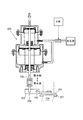
次に、本実施例の電動アクチュエータの詳細を図1および図2に基づいて説明する。
電動アクチュエータは、ロッド4、スラスト軸受5およびコイルスプリング6の他に、電力の供給を受けて駆動力(モータトルク)を発生する電動モータMと、この電動モータMの回転を2段減速する減速機構と、この減速機構の回転運動を往復直線運動に変換する変換機構と、電動アクチュエータのロッド4のストローク位置を検出するストローク量検出装置(磁性移動体8、ストロークセンサS)と、これらの各構成部品を収容するアクチュエータケースとを備えている。
Next, details of the electric actuator of this embodiment will be described with reference to FIGS.
The electric actuator includes, in addition to the
減速機構は、3つの減速ギヤにより構成されている。減速機構は、電動モータMのモータシャフト(回転軸、出力軸)13、このモータシャフト13に対して並列配置された2つの第1、第2支持軸(中間ギヤシャフト、最終ギヤシャフト)14、15、モータシャフト13に固定されたピニオンギヤ(モータギヤ)16、このピニオンギヤ16と噛み合って回転する中間ギヤ(駆動ギヤ、第1ギヤ)17、およびこの中間ギヤ17と噛み合って回転する最終ギヤ(従動ギヤ、第2ギヤ、平歯車)18等によって構成されている。
変換機構は、回転するプレートカム21、このプレートカム21のカム溝22内に移動自在に挿入されるフォロワ23、およびこのフォロワ23を回転自在に支持するピボットピン24等によって構成されている。
The reduction mechanism is composed of three reduction gears. The speed reduction mechanism includes a motor shaft (rotary shaft, output shaft) 13 of the electric motor M, two first and second support shafts (intermediate gear shaft, final gear shaft) 14 arranged in parallel to the
The conversion mechanism includes a
ここで、電動アクチュエータのアクチュエータケースは、電動モータMを収容保持すると共に、減速機構および変換機構を回転自在に収容するギヤハウジング26と、このギヤハウジング26の開口部を塞ぐセンサカバー(蓋体)とを備えている。
ギヤハウジング26は、ステンレス鋼等の非磁性材料によって形成されている。また、センサカバーは、電気絶縁性に優れる樹脂材料等の非磁性材料によって形成されている。 ここで、ギヤハウジング26の側壁よりバルブ側に位置する円筒状のベアリングホルダ28には、ロッド4の軸方向に貫通する軸受孔が形成されている。この軸受孔の孔壁面には、スラスト軸受5が圧入嵌合されている。また、ギヤハウジング26の側壁よりバルブ側に突出する円筒状のスプリングホルダ29内には、コイルスプリング6が収容されている。
Here, the actuator case of the electric actuator accommodates and holds the electric motor M, and a
The
電動アクチュエータのロッド4は、そのロッド軸中心線方向と同一方向のストローク方向に真っ直ぐに延びている。このロッド4は、フォロワ23およびピボットピン24を介して、プレートカム21に連結(接続)するプレート(平板)状の第1ロッド31と、リンク機構(リンクレバー3等)を介して、ウェイストゲートバルブ1のシャフト2に連結(接続)するプレート(平板)状の第2ロッド32と、第1ロッド31と第2ロッド32とを連結する断面円形状の接続ロッド33とによって構成されている。なお、第1ロッド31、第2ロッド32および接続ロッド33は、例えばステンレス鋼等の金属材料(非磁性体)によって形成されており、溶接等により接続されて一体部品となっている。
The
第1ロッド31は、フォロワ23およびピボットピン24を介して、プレートカム21から荷重を受ける入力部である。この第1ロッド31の表面は、磁性移動体8をネジ締結固定するための磁性移動体搭載面となっている。なお、磁性移動体8をロッド4の第1ロッド31に樹脂モールド成形することで固定しても良い。
また、第1ロッド31の一端部(接続ロッド33側に対して反対側の端部)には、ピボットピン24が嵌合する嵌合孔が形成されている。なお、ピボットピン24は、第1ロッド31の裏面側から打ち込まれて表面側に突出して第1ロッド31に接続(固定)されている。
また、第1ロッド31の他端部には、接続ロッド33の軸線方向の一端側と溶接により接続される第1連結部35が設けられている。
The
A fitting hole into which the
The other end of the
第2ロッド32は、リンクレバー3および第1、第2ヒンジピン11、12を介して、ウェイストゲートバルブ1に荷重を与える出力部である。この第2ロッド32の一端部(接続ロッド33側の端部)には、接続ロッド33の軸線方向の他端側と溶接により接続される第2連結部36が設けられている。
第2ロッド32の他端部(接続ロッド33側に対して反対側の端部)には、第1ヒンジピン11が嵌合する嵌合孔(図示せず)が形成されている。なお、第1ヒンジピン11は、第2ロッド32の裏面側から打ち込まれて表面側に突出して第2ロッド32に接続(固定)されている。
The
A fitting hole (not shown) into which the
接続ロッド33は、第1ロッド31の第1連結部35と第2ロッド32の第2連結部36とを連結する中継部である。この接続ロッド33の第1ロッド31側端部の外周には、コイルスプリング6からストローク方向のバルブ全閉側に付勢する荷重を受け止める荷重受け部である円環状(鍔状、フランジ状)のスプリングシート37が装着されている。また、接続ロッド33は、スラスト軸受5の軸受中心を中心に揺動自在で、且つスラスト軸受5の軸線方向に摺動自在に支持されている。なお、スプリングシート37は、ロッド4の第1ロッド31の第1連結部35の端面に係止されている。
The connecting
スラスト軸受5は、ロッド4の接続ロッド33をそのストローク方向(往復移動方向)に摺動自在に支持するものである。このスラスト軸受5の内部には、ロッド4の軸方向に貫通する貫通孔(摺動孔)が形成されている。また、スラスト軸受5の内周面(ロッド4の接続ロッド33と摺動する摺動面)は、スラスト軸受5の軸受中心付近で最もロッド軸中心線側に突出する凸曲面となっている。これにより、ロッド4の接続ロッド33の揺動(振れ)が許容される。
The
コイルスプリング6は、ロッド4に対して、ウェイストゲートバルブ1を閉じる側(ロッド軸中心線方向のバルブ全閉側)に付勢する付勢力(荷重)を発生するロッド(バルブ)付勢手段である。このコイルスプリング6の一端は、スプリングシート37に保持され、コイルスプリング6の他端は、ベアリングホルダ28の端部とスプリングホルダ29とを連結する円環状の隔壁(閉鎖壁)38に保持されている。
これによって、電動アクチュエータのロッド4、特に第1ロッド31には、コイルスプリング6からのスプリング荷重(バルブ全閉側に付勢する荷重)が作用している。
The
As a result, the spring load from the coil spring 6 (the load urging the valve fully closed) acts on the
減速機構は、電動モータMのトルクを変換機構に伝達する動力伝達機構を構成する。この減速機構は、上述したように、中間ギヤシャフト14、最終ギヤシャフト15、ピニオンギヤ16、中間ギヤ17および最終ギヤ18等によって構成されている。
中間ギヤシャフト14および最終ギヤシャフト15は、互いに並列配置されている。また、3つのギヤ16〜18は、ギヤハウジング26の減速ギヤ収納空間内において回転自在に収容されている。
The speed reduction mechanism constitutes a power transmission mechanism that transmits the torque of the electric motor M to the conversion mechanism. As described above, the speed reduction mechanism includes the
The
中間ギヤシャフト14は、ギヤハウジング26の嵌合孔に打ち込まれてギヤハウジング26の嵌合部に圧入固定されている。この中間ギヤシャフト14の軸方向中心線は、中間ギヤ17の回転中心を構成している。また、中間ギヤシャフト14の外周には、2つのベアリング(軸受:図示せず)を介して、中間ギヤ17が回転自在に支持されている。なお、2つのベアリングは設けなくても良い。
また、中間ギヤシャフト14の中間ギヤ17の端面より突出した突出部の外周には、円環状の周方向溝が形成されている。この周方向溝には、中間ギヤシャフト14の外周に中間ギヤ17を嵌め合わせた際に、中間ギヤシャフト14からの中間ギヤ17の抜け止めを行うワッシャおよびCリング等の中間ギヤ抜け止め手段が装着されている。
The
An annular circumferential groove is formed on the outer periphery of the protruding portion protruding from the end face of the
最終ギヤシャフト15は、ギヤハウジング26の嵌合孔に打ち込まれて円筒状の嵌合部に圧入固定されている。この最終ギヤシャフト15の軸方向中心線は、最終ギヤ18の回転中心を構成している。また、最終ギヤシャフト15の外周には、2つのベアリング(軸受)を介して、最終ギヤ18が回転自在に支持されている。なお、2つのベアリングは設けなくても良い。
また、最終ギヤシャフト15の最終ギヤ18の端面より突出した突出部の外周には、円環状の周方向溝が形成されている。この周方向溝には、最終ギヤシャフト15の外周に最終ギヤ18を嵌め合わせた際に、最終ギヤシャフト15からの最終ギヤ18の抜け止めを行うワッシャおよびCリング等の最終ギヤ抜け止め手段が装着されている。
The
Further, an annular circumferential groove is formed on the outer periphery of the protruding portion that protrudes from the end face of the
ピニオンギヤ16は、金属材料または樹脂材料によって形成されている。このピニオンギヤ16は、モータシャフト13の外周に圧入固定されている。ピニオンギヤ16の外周には、中間ギヤ17と噛み合う複数の凸状歯(ピニオンギヤ部)41が周方向全体に形成されている。
中間ギヤ17は、金属材料または樹脂材料によって形成されており、中間ギヤシャフト14の外周に回転自在に嵌め合わされている。この中間ギヤ17は、中間ギヤシャフト14の周囲を周方向に取り囲むように設置された円筒部を有している。この円筒部の外周には、円環状の最大外径部(径大部)が一体的に形成されている。
The
The
中間ギヤ17の径大部の外周には、ピニオンギヤ16の凸状歯41と噛み合う複数の凸状歯(大径ギヤ部)42が周方向全体に形成されている。また、円筒部(径小部)の外周には、最終ギヤ18と噛み合う複数の凸状歯(小径ギヤ部)43が周方向全体に形成されている。
最終ギヤ18は、金属材料または樹脂材料によって形成されており、2つのベアリングを介して、最終ギヤシャフト15の外周に回転自在に嵌め合わされている。この最終ギヤ18は、最終ギヤシャフト15の周囲を周方向に取り囲むように設置された円筒部を有している。この円筒部には、円筒部の外周面より扇状に広がるフランジ44を有している。 最終ギヤ18のフランジ44の外周部には、中間ギヤ17の凸状歯43と噛み合う複数の凸状歯(扇状の大径ギヤ部)45が所定の角度分だけ扇状に形成されている。
On the outer periphery of the large-diameter portion of the
The
変換機構は、最終ギヤ18の回転運動をロッド4の直線運動に変換する運動方向変換機構である。この変換機構は、最終ギヤ18の最終ギヤシャフト15を中心にして最終ギヤ18と一体的に回転するプレートカム21、このプレートカム21のカム溝22内に移動自在に挿入されるフォロワ23、およびこのフォロワ23を回転自在に支持するピボットピン24等によって構成されている。
The conversion mechanism is a movement direction conversion mechanism that converts the rotational movement of the
プレートカム21は、金属材料によって所定の形状に形成されており、最終ギヤ18のカム装着部に固定されている。なお、最終ギヤ18が樹脂材料で形成されている場合、プレートカム21は最終ギヤ18にインサート成形される。また、最終ギヤ18が金属材料で形成されている場合、最終ギヤ18とプレートカム21とを焼結金属等で一体化しても良い。このように構成することで、最終ギヤ18の回転軸とプレートカム21の回転軸とが共通化されるため、最終ギヤ18の回転中心(最終ギヤシャフト15の回転中心)とプレートカム21の回転中心とが一致する。また、最終ギヤ18の作動角度(最終ギヤ作動角)とプレートカム21の回転角度(カム回転角)とが等しくなる。
プレートカム21のカム溝22は、ウェイストゲートバルブ1の動作パターンに対応した湾曲形状のガイド部である。
ここで、プレートカム21のカム形状およびプレートカム21の回転角度は、ウェイストゲートバルブ1を全閉位置から全開位置まで駆動するのに必要なロッドストローク量に対して決定される。
The
The
Here, the cam shape of the
フォロワ23は、金属材料によって円筒形状に形成されており、ピボットピン24の外周に回転自在に嵌め合わされている。このフォロワ23は、ピボットピン24の周囲を周方向に取り囲むように円筒部を有している。
ピボットピン24は、ロッド4の嵌合孔に打ち込まれてロッド4に圧入固定されている。なお、ピボットピン24のフォロワ23の円筒部の端面より突出した突出部には、フォロワ23の抜け止めを行うために潰されて鍔状にカシメられたフランジが形成されている。
また、フォロワ23の回転中心は、プレートカム21の回転中心と共に、ロッド4のストローク方向の中心線上、つまりロッド軸中心線上に設置されている。
The
The
Further, the rotation center of the
電動モータMは、電動アクチュエータの動力源であって、ギヤハウジング26のモータ収納空間内に収容保持されている。この電動モータMは、ECUによって通電制御されるように構成されている。
そして、ECUには、CPU、ROM、RAM等の機能を含んで構成される周知の構造のマイクロコンピュータが設けられている。そして、ECUは、ストロークセンサS、クランク角度センサ、アクセル開度センサ、スロットル開度センサ、過給圧センサおよび車速センサ等の各種センサのセンサ出力信号に基づいて、スロットルバルブの電動アクチュエータ、ウェイストゲートバルブ1の電動アクチュエータを制御する。
The electric motor M is a power source of the electric actuator and is housed and held in the motor housing space of the
The ECU is provided with a microcomputer having a known structure that includes functions of a CPU, a ROM, a RAM, and the like. Then, the ECU performs an electric actuator for the throttle valve, a waste gate based on sensor output signals of various sensors such as a stroke sensor S, a crank angle sensor, an accelerator opening sensor, a throttle opening sensor, a boost pressure sensor, and a vehicle speed sensor. The electric actuator of the
次に、本実施例のストローク量検出装置の詳細を図1ないし図6に基づいて簡単に説明する。
ストローク量検出装置は、ロッド4に一体的に設置された磁性移動体8と、この磁性移動体8のストローク位置を検出するストロークセンサSとを備えている。
なお、ECUは、ストロークセンサSから出力される出力値(センサ出力値)に基づいて、電動アクチュエータのロッド4の直線的なストローク位置を演算(検出)するロッドストローク検出手段としての機能を有している。
Next, details of the stroke amount detection device of the present embodiment will be briefly described with reference to FIGS.
The stroke amount detection device includes a magnetic moving
The ECU has a function as rod stroke detecting means for calculating (detecting) the linear stroke position of the
磁性移動体8は、検出対象物であるロッド4のストローク方向への移動に伴って直線変位(移動)するように、ロッド4に一体的に設置(締結一体化)されている。この磁性移動体8は、平行な一定の磁束密度の磁界を発生する2つの第1、第2マグネット(磁石)51、52、およびこれらの磁石51、52の磁極面から放出された磁束(磁界)をストロークセンサSに対して集中させる長方形枠体状の磁性フレーム(磁性体)等によって構成されている。 2つの磁石51、52は、直方体形状に形成されており、ストロークセンサSに向けて磁束(磁界)を放出する永久磁石である。これらの磁石51、52は、板長さ方向および板幅方向に対して直交する板厚さ方向の両端部が互いに極性が逆向きになるようにN極とS極とが着磁されている。また、2つの磁石51、52は、磁石内部の磁力線の向きが互いに平行となるように平行着磁されている。また、2つの磁石51、52は、所定のエアギャップを隔てて対向して配置されている。
The magnetic
また、2つの磁石51、52は、ロッド軸中心線に対して直交する垂直方向に着磁されている。また、2つの磁石51、52は、互いに対向する磁極面同士が同一極性(例えばN極)となるように着磁されている。なお、図1に示した矢印方向は、2つの磁石51、52の磁極面から放出される磁束線の方向(磁界方向)を示す。
これにより、磁石51の着磁方向(板厚さ方向)は、ロッド軸中心線に対して直交する垂直方向と一致しており、磁石51の板厚さ方向の一方側(図1において図示上方側)の磁極面がS極とされ、また、磁石51の板厚さ方向の他方側(図1において図示下方側)の磁極面がN極とされている。また、磁石52の着磁方向(板厚さ方向)は、ロッド軸中心線に対して直交する垂直方向と一致しており、磁石52の板厚さ方向の一方側(図1において図示上方側)の磁極面がN極とされ、また、磁石52の板厚さ方向の他方側(図1において図示下方側)の磁極面がS極とされている。
The two
Thereby, the magnetizing direction (plate thickness direction) of the
磁性体は、閉磁路を形成する鉄、ニッケル、フェライト等の磁性材料によって形成されている。この磁性体は、長手方向、つまりロッド軸中心線に沿うように延びる直方体形状の上下ブロック(ロッド軸方向ブロック:以下ブロックと略す)54、55、および短手方向、つまりロッド軸中心線に対して直交する垂直線に沿うように延びる直方体形状の左右ブロック(ロッド垂直方向ブロック:以下ブロックと略す)56、57によって構成されている。また、磁性体は、ロッド4の第1ロッド31の磁性移動体搭載面上に締結ネジや締結ボルト等のスクリュー58を用いて締め付け固定される複数のブラケット59を有している。
ブロック54、55の中央部は、エアギャップを隔てて対向して配置されたマグネット(磁石)保持部を有している。ブロック54、55のマグネット保持部の内側面(対向面)には、磁石51、52の磁極面(極性が共にS極)が接触した状態で磁石51、52が接着剤等の固定手段を用いて保持固定されている。
なお、磁石をストロークセンサS側に設置して磁性移動体8を磁性体のみで構成しても良い。
The magnetic body is made of a magnetic material such as iron, nickel, or ferrite that forms a closed magnetic path. This magnetic body has a rectangular parallelepiped upper and lower block (rod axis direction block: hereinafter abbreviated as a block) 54 and 55 extending along the longitudinal direction, that is, the rod axis center line, and the short direction, that is, the rod axis center line. And right and left blocks (rod vertical block: hereinafter abbreviated as “blocks”) 56 and 57 extending along a perpendicular line perpendicular to each other. In addition, the magnetic body has a plurality of
The center part of the
In addition, a magnet may be installed in the stroke sensor S side and the magnetic moving
ストロークセンサSは、磁性移動体8を構成する2つの磁石51、52および磁性体を伴って構成される磁気回路の途中に位置するように、つまり磁性移動体8で周囲を囲まれたセンサ収容空間内に位置するようにセンサカバーのセンサ搭載部(センサホルダ)に保持されている。このストロークセンサSは、センサカバーのセンサ搭載部(センサホルダ)からロッド4の第1ロッド31側に突出するように設置されている。
また、ストロークセンサSは、磁性移動体8のストローク方向への移動に伴って変化する磁束(磁束密度、磁界分布、磁界強さ)を検出する非接触式の磁気検出素子であるホール素子を有している。このホール素子には、磁性移動体8、特に2つの磁石51、52の磁極面(N極)から印加される磁界の磁束密度を感磁する感磁面Fが設けられている。
The stroke sensor S is located in the middle of the magnetic circuit including the two
The stroke sensor S has a Hall element that is a non-contact type magnetic detection element that detects magnetic flux (magnetic flux density, magnetic field distribution, magnetic field strength) that changes as the magnetic moving
そして、ストロークセンサSは、ホール素子の感磁面Fを鎖交する磁束密度に対応した電気信号(電圧信号、センサ出力信号:以下センサ出力値と言う)をECUに向けて出力するホールICを主体に構成されている。このホールICは、ホール素子と増幅回路とを一体化したICチップのことであって、磁性体の内部に形成される長方形状のセンサ収容空間内において、磁性移動体8に対して相対的に移動可能に設置されている。なお、非接触式の磁気検出素子として、ホールICの代わりに、ホール素子単体または磁気抵抗素子(MR素子)を使用しても良い。
The stroke sensor S includes a Hall IC that outputs an electrical signal (voltage signal, sensor output signal: hereinafter referred to as a sensor output value) corresponding to the magnetic flux density interlinking the magnetic sensing surface F of the Hall element to the ECU. Consists of the subject. The Hall IC is an IC chip in which a Hall element and an amplifier circuit are integrated, and is relatively relative to the magnetic moving
ここで、磁性移動体8およびストロークセンサSにより構成される磁気回路は、ウェイストゲートバルブ1が全閉位置にある時、図1に実線で示した位置に保持される。また、磁気回路は、ウェイストゲートバルブ1が全開閉位置にある時、図1に二点鎖線で示した位置および図2で実線で示した位置に保持される。
また、磁気回路は、磁石51、ホール素子を有するホールIC、磁性体のブロック57およびブロック54により構成される閉磁路型の第1磁気回路、磁石51、磁性体のブロック56およびブロック54により構成される閉磁路型の第2磁気回路、磁石52、ホール素子を有するホールIC、磁性体のブロック57およびブロック55により構成される閉磁路型の第3磁気回路、並びに磁石52、磁性体のブロック56およびブロック55により構成される閉磁路型の第4磁気回路等を有している。
Here, the magnetic circuit constituted by the magnetic
The magnetic circuit includes a
また、ストロークセンサSは、ウェイストゲートバルブ1が全閉位置と全開位置との間にある場合、磁性移動体8のストローク位置(基準位置に対する相対位置)とロッド4のストローク量とが対応しており、また、ロッド4のストローク位置とウェイストゲートバルブ1のバルブ開度とが対応している。このため、ECUは、磁性移動体8のストローク位置、つまり磁束密度の変化に対応して出力されるセンサ出力信号を測定して、ロッド4のストローク量を求め、このロッド4のストローク量からウェイストゲートバルブ1のバルブ開度を求め、このバルブ開度からウェイストゲート流路9を流れる排気ガスの流量を求めることが可能である。
In addition, when the
ここで、磁性移動体8のストローク位置をセンシングする方式として、ホールIC、ホール素子またはMR素子を使用して、非接触での磁気検出で実施する場合、磁性移動体8とストロークセンサSのホールICとで構成される第1、第2磁気回路の近傍に鉄等の磁性体があると、非接触式の磁気検出素子が検出する磁場が安定して確保できない可能性がある。そこで、本実施例の電動アクチュエータを構成する機能部品、つまり第1、第2磁気回路に近接配置される機能部品であるロッド4、最終ギヤ18、プレートカム21、フォロワ23、ピボットピン24、最終ギヤシャフト15を非磁性材料(ステンレス鋼等の非磁性金属、非磁性樹脂等)で構成することで、第1、第2磁気回路への外乱磁界の影響を回避している。
Here, as a method of sensing the stroke position of the magnetic moving
次に、本実施例のリンクレバー3およびロッド4の詳細を図1ないし図6に基づいて説明する。
リンクレバー3の第1結合部(ロッド4のストローク方向の先端部との結合部である第1ヒンジピン11)は、ウェイストゲートバルブ1を動かすと、つまり全閉位置から全開位置に至るまで回転動作(開閉)すると、ウェイストゲートバルブ1の回転中心軸と同一軸心上に位置する回転軸(リンクレバー3の回転中心、第2ヒンジピン12の中心)を中心にした所定の曲率半径の曲線である回転作動線(リンクレバー3の回転作動線:図示二点鎖線)上を移動する。
Next, details of the
The first coupling portion of the link lever 3 (the
そして、リンクレバー3の回転作動線とは、ウェイストゲートバルブ1が全閉開度となるリンクレバー3の回転作動線上の回転作動点を、リンクレバー3の回転作動線上の全閉点とし、ウェイストゲートバルブ1が全開開度となるリンクレバー3の回転作動線上の回転作動点を、リンクレバー3の回転作動線上の全開点としたとき、リンクレバー3の回転作動線上の全閉点とリンクレバー3の回転作動線上の全開点とを、ウェイストゲートバルブ1の回転中心軸(リンクレバー3の回転軸、第2ヒンジピン12の中心)Oを中心にした所定の曲率半径の曲線で結んだ円弧軌跡のことである。
The rotation operation line of the
ここで、ウェイストゲートバルブ1の全閉位置とは、図4および図5(a)に示したように、ウェイストゲートバルブ1がバルブシート10に着座してウェイストゲート流路9を閉鎖している全閉開度の状態のことである。
また、ウェイストゲートバルブ1の全開位置とは、図5(b)に示したように、ウェイストゲートバルブ1がバルブシート10より離脱してウェイストゲート流路9を開放している全開開度の状態のことである。
また、図6に示した中間開度とは、ウェイストゲートバルブ1の全閉開度と全開開度との中間の開度(中央値)のことである。
Here, the fully closed position of the
Further, the fully open position of the
Moreover, the intermediate opening degree shown in FIG. 6 is an intermediate opening degree (median value) between the fully closed opening degree and the fully opening opening degree of the
そして、本実施例では、図4に示したように、ウェイストゲートバルブ1が全閉開度となるリンクレバー3の回転作動線上の回転作動点が、リンクレバー3の回転作動線上の全閉点Aとして設定されている。
また、ウェイストゲートバルブ1が全開開度となるリンクレバー3の回転作動線上の回転作動点は、リンクレバー3の回転作動線上の全開点Bとして設定されている。
また、ウェイストゲートバルブ1が全閉位置と全開位置との中間の開度となるリンクレバー3の回転作動線上の回転作動点は、リンクレバー3の回転作動線上の中間開度点Cとして設定されている。
また、全閉点Aと全開点Bとを結ぶ直線から半径方向の外側に向けて最も遠く、しかも全閉点Aと全開点Bとの間にあるリンクレバー3の回転作動線上の回転作動点は、リンクレバー3の回転作動線上の振れ幅の端点Pとして設定されている。
In the present embodiment, as shown in FIG. 4, the rotation operating point on the rotation operating line of the
In addition, the rotation operation point on the rotation operation line of the
The rotation operating point on the rotation operating line of the
Further, the rotational operating point on the rotational operating line of the
以上のように、リンクレバー3の回転作動線上に各回転作動点を設定したとき、リンクレバー3の回転作動線上の振れ幅の端点Pが、全閉点Aと中間開度点Cとの間、特に全閉点Aと中間開度点Cとの中央(値)に位置するように設定されている。
また、リンクレバー3の回転軸(リンクレバー3の回転中心O)とリンクレバー3の回転作動線上の振れ幅の端点Pとを結ぶ直線と、電動アクチュエータのロッド4の軸線方向の中心線(ロッド軸中心線)との交差角度は、直角(90°)となるように設定されている。
なお、リンクレバー3の回転作動線とは、リンクレバー3の回転作動線上の全閉点Aとリンクレバー3の回転作動線上の全開点Bとを、リンクレバー3の回転軸(ウェイストゲートバルブ1の回転中心軸)Oを中心にした所定の曲率半径の曲線で結んだ円弧軌跡のことである。
また、図5の矢印は、リンクレバー3の可動範囲(リンクレバー3の回転(動作)可能な回転角度)を示す。
As described above, when each rotation operation point is set on the rotation operation line of the
Further, a straight line connecting the rotation axis of the link lever 3 (rotation center O of the link lever 3) and the end point P of the swing width on the rotation operation line of the
The rotation operation line of the
5 indicates a movable range of the link lever 3 (a rotation angle at which the
[実施例1の作用]
次に、本実施例のウェイストゲートバルブ1の開閉制御を行う電動アクチュエータの作動を図1ないし図6に基づいて簡単に説明する。
[Operation of Example 1]
Next, the operation of the electric actuator for performing opening / closing control of the
ECUは、過給圧センサにより検出される過給圧が設定値に満たない場合、ウェイストゲートバルブ1が全閉状態となるように、電動モータMへの電力供給を制御する。
これによって、電動アクチュエータの構成部品が、全閉状態に止まるため、ウェイストゲートバルブ1が全閉状態を継続する。これにより、ウェイストゲート流路9は閉鎖される。この結果、エンジンより排出された排気ガスの全量は、ターボチャージャのタービンハウジング7の入口部から流入してタービンインペラを回転させ、タービンハウジング7の出口部から排出される。
一方、吸気管内に吸い込まれた吸入空気は、タービンインペラの回転により駆動されるコンプレッサインペラによって圧縮されて圧力(過給圧)が上昇する。そして、圧力が上昇した吸入空気は、エンジンに吸い込まれる。
The ECU controls the power supply to the electric motor M so that the
As a result, the components of the electric actuator remain in the fully closed state, so that the
On the other hand, the intake air sucked into the intake pipe is compressed by the compressor impeller driven by the rotation of the turbine impeller, and the pressure (supercharging pressure) increases. The intake air whose pressure has increased is sucked into the engine.
ECUは、過給圧センサにより検出される過給圧が設定値以上に上昇した場合、つまり予め設定された最大過給圧を超える場合、ウェイストゲートバルブ1が全開状態となるように、電動モータMへの電力供給を制御する。
これによって、電動モータMのモータシャフト13が全開方向に回転する。これにより、モータトルクが、ピニオンギヤ16、中間ギヤ17、最終ギヤ18に伝達される。そして、最終ギヤ18からモータトルクが伝達されたプレートカム21が、最終ギヤ18の回転に伴って所定の回転角度(最終ギヤ18の作動角度と等しい回転角度)だけ全開方向に回転する。
すると、ピボットピン24がカム溝22を摺動(滑動)して、カム溝22の全閉位置から全開位置まで移動することにより、ロッド4の第1ロッド31がコイルスプリング6を圧縮しながらロッド4のストローク方向のバルブ開側に直線移動する(押し出される)。すると、ロッド4の直線移動に伴って、第1、第2ロッド31、32および接続ロッド33がロッド4のストローク方向のバルブ開側に直線移動する。
The ECU controls the electric motor so that the
As a result, the
Then, the
さらに、第2ロッド32の直線移動に伴って、第1ヒンジピン11がロッド4のストローク方向のバルブ開側にロッド4が直線移動することにより、リンクレバー3が第2ヒンジピン12を中心にして全開方向に回転する。すると、第2ヒンジピン12の回転に伴ってウェイストゲートバルブ1も第2ヒンジピン12を中心にして全開方向に回転する。これにより、ウェイストゲートバルブ1がバルブシートより離脱して全開状態となるため、ウェイストゲート流路9が開放される。
この結果、エンジンからタービンハウジング7の入口部に流入した排気ガスの一部がタービンインペラをバイパスするウェイストゲート流路9を通ってタービンハウジング7の出口部に排出される。これにより、タービンインペラに作用する排気エネルギーが減少し、タービンインペラの回転速度が低下するので、ターボチャージャの過回転が防止される。
また、過給圧または排気圧が過大とならないようになる。また、タービンインペラの過回転に伴うタービンインペラの破損等を防止できる。
Further, as the
As a result, a part of the exhaust gas flowing from the engine to the inlet portion of the
In addition, the supercharging pressure or the exhaust pressure does not become excessive. Further, it is possible to prevent the turbine impeller from being damaged due to excessive rotation of the turbine impeller.
ECUは、過給圧センサにより検出される過給圧が設定値よりも低下した場合、ウェイストゲートバルブ1が全閉状態となるように、電動モータMへの電力供給を制御する。
これによって、電動モータMのモータシャフト13が全閉方向に回転する。これにより、モータトルクが、ピニオンギヤ16、中間ギヤ17、最終ギヤ18、プレートカム21に伝達される。そして、プレートカム21が、最終ギヤ18の回転に伴って所定の回転角度だけ全閉方向に回転する。
すると、ピボットピン24がカム溝22を摺動(滑動)して、カム溝22の全開位置から全閉位置まで移動することにより、ロッド4のストローク方向のバルブ閉側にロッド4が直線移動する(引き戻される)。すると、ロッド4の直線移動に伴って第1、第2ロッド31、32および接続ロッド33がロッド4のストローク方向のバルブ閉側に直線移動する。
The ECU controls power supply to the electric motor M so that the
As a result, the
Then, the
さらに、第2ロッド32の直線移動に伴って、第1ヒンジピン11がロッド4のストローク方向のバルブ閉側に直線移動することにより、リンクレバー3が第2ヒンジピン12を中心にして全閉方向に回転する。すると、第2ヒンジピン12の回転に伴ってウェイストゲートバルブ1も第2ヒンジピン12を中心にして全閉方向に回転する。これにより、ウェイストゲートバルブ1がバルブシートに着座して全閉状態となるため、ウェイストゲート流路9が閉鎖される。
また、ウェイストゲートバルブ1は、エンジンの運転状況、特に過給圧センサにより検出される過給圧に基づいて、全閉位置と全開位置との中間の中間開度に設定するように制御される。この場合、ウェイストゲートバルブ1のバルブ開度が過給圧に基づいて連続的または段階的に変更されるため、ウェイストゲート流路9を通過する排気ガスの流量を連続的または段階的に微調整できる。これにより、エンジンの過給圧を連続的または段階的に可変制御できる。
Further, as the
The
[実施例1の特徴1]
以上のように、本実施例のウェイストゲートバルブ制御装置においては、ウェイストゲートバルブ1のシャフト2と電動アクチュエータのロッド4との間に、ロッド4の直線運動をウェイストゲートバルブ1の回転運動に変換するリンクレバー3等のリンク機構を設置している。また、電動アクチュエータにおいては、リンクレバー3を介して、ウェイストゲートバルブ1に連結するロッド4に磁性移動体8を一体的に設置している。
そして、ストロークセンサSのホールICによってロッド4の第1ロッド31と一体で動く磁性移動体8のストローク位置を検出しているので、電動アクチュエータの最終作動段であるロッド4のストローク位置を直接検出することができる。この結果、ロッド4のストローク位置の検出精度が向上するため、ロッド4のストローク量の制御性、つまりウェイストゲートバルブ1の開度制御の制御性を向上することができる。
また、ストロークセンサSのホールICで検出される磁性移動体8のストローク位置が、所定時間が経過しても設定された目標位置に到達または接近しない場合には、ロッド4または電動アクチュエータの故障(例えばウェイストゲートバルブ1またはロッド4の作動不能状態等)と判断することができる。つまりウェイストゲートバルブ1、ロッド4または電動アクチュエータの故障診断を実施できる。これにより、OBD要件を満足できる。
[
As described above, in the waste gate valve control device of this embodiment, the linear motion of the
Since the stroke position of the magnetic moving
Further, if the stroke position of the magnetic moving
[実施例1の特徴2]
また、本実施例のウェイストゲートバルブ制御装置においては、リンクレバー3の結合部(電動アクチュエータのロッド4との結合部である第1ヒンジピン11)が、ウェイストゲートバルブ1が回転動作(開閉)する際に、全閉点Aと全開点Bとを円弧状曲線(円弧軌跡)で結ぶ回転作動線上を移動するように構成されている。
ここで、リンクレバー3の回転作動線上の各回転作動点は、図4に示したように、リンクレバー3の回転作動線上の全閉点A、リンクレバー3の回転作動線上の全開点B、リンクレバー3の回転作動線上の中間開度点C、およびリンクレバー3の回転作動線上の振れ幅の端点Pのように設定されている。
以上のように、リンクレバー3の回転作動線上に各回転作動点を設定したとき、ウェイストゲートバルブ1が回転動作(開閉)する際、リンクレバー3の回転作動線上の振れ幅の端点Pを、全閉点Aと中間開度点Cとの間、特に全閉点Aと中間開度点Cとの中央に位置するように設定している。
[
Further, in the waste gate valve control apparatus of the present embodiment, the
Here, as shown in FIG. 4, the rotation operation points on the rotation operation line of the
As described above, when each rotation operation point is set on the rotation operation line of the
以上のように、ウェイストゲートバルブ制御装置においては、ウェイストゲートバルブ1が回転動作(開閉)する際、リンクレバー3の回転作動線上の振れ幅の端点Pが、全閉点Aと中間開度点Cとの間に位置するように設定されているので、図5に示したように、従来例1及び2と比べて、電動アクチュエータのロッド4の軸振れ量(ロッド軸振れ量δ)を小さくすることができる。これによって、ロッド4のストローク量を直接検出する際におけるロッド4の軸振れによる検出誤差を小さくすることができる。
また、リンクレバー3の回転作動線上の振れ幅の端点Pを、全閉点Aと中間開度点Cとの中央に位置するように設定されているので、図6に示したように、ウェイストゲートバルブ1においてロッド4のストローク方向への移動量(ストローク量)に対する排気ガス流量(または圧力)Qの変化率(流量変化率)が最も大きい低開度領域(中間開度よりも全閉側の領域)でのロッド4の軸振れ量(リンクレバー3の回転角度当たりに対するロッド4の軸振れ幅)、つまり高い精度が必要な全閉点Aから中間開度点Cまでの領域でのロッド4の軸振れ量(リンクレバー3の回転角度当たりに対するロッド4の軸振れ幅)を最小に設定できる。これにより、ストロークセンサSによるロッド4のストローク量の検出精度の向上およびロッド4のストローク量の制御性の向上を図ることができる。
As described above, in the waste gate valve control device, when the
Further, since the end point P of the swing width on the rotation operating line of the
[実施例1の特徴3]
また、ウェイストゲートバルブ制御装置においては、リンクレバー3の回転中心点Oとリンクレバー3の回転作動線上の振れ幅の端点Pとを結ぶ直線と、ロッド4の軸線方向の中心線(ロッド軸中心線)との交差角度を直角となるように設定している。これにより、ロッド4の振れ幅を最小に設定することができる。これによって、ロッド4のストローク量を直接検出する際におけるロッド4の軸振れによる検出誤差を小さくすることができる。また、ストロークセンサSによるロッド4のストローク量の検出精度の向上およびロッド4のストローク量の制御性の向上を図ることができる。
また、電動アクチュエータには、ロッド4の軸振れを許容しつつ、ロッド4をその軸線方向(ロッド軸方向)に摺動自在に支持するスラスト軸受5が設置されている。そして、上述したように、リンクレバー3の回転作動線上の振れ幅の端点Pを、全閉点Aと中間開度点Cとの間に位置するように設定することにより、ロッド4の軸振れ量を小さくすることができる。これにより、スラスト軸受5に大きな力が加わったり、ロッド4がスラスト軸受5の内周をこじったり、ロッド4とスラスト軸受5とが偏摩耗したり、ロッド4が作動不能に陥ったりするという不具合の発生を抑えることができる。
[
In the waste gate valve control apparatus, the straight line connecting the rotation center point O of the
The electric actuator is provided with a
[変形例]
本実施例では、本発明のバルブ制御装置を、ウェイストゲートバルブ1を駆動する電動アクチュエータを制御するウェイストゲートバルブ制御装置に適用しているが、本発明のバルブ制御装置を、EGRガス等の排気ガスの流量を制御(調整)する排気ガス流量制御弁の弁体(バルブ)、EGRクーラを通過するEGRガス量とEGRクーラを迂回するEGRガス量との比率を制御(調整)する排気ガス温度制御弁の弁体(バルブ)を駆動する電動アクチュエータを制御するバルブ制御装置に適用しても良い。
[Modification]
In this embodiment, the valve control device of the present invention is applied to a waste gate valve control device that controls an electric actuator that drives the
本実施例では、アクチュエータとして、リンクレバー3を介してウェイストゲートバルブ1に連結するロッド4を、電動モータMの駆動力を利用して軸線方向(ストローク方向)に往復移動させることでウェイストゲートバルブ1を駆動する電動アクチュエータを用いているが、アクチュエータとして、レバーを介してバルブに連結するロッドを、電磁力または流体圧力を利用して軸線方向(ストローク方向)に往復移動させることでバルブを駆動する電磁アクチュエータまたは流体圧アクチュエータを用いても良い。
なお、ウェイストゲートバルブ1の他に、流路を流れる流体を制御する流体制御弁の弁体(バルブ)を開閉制御するバルブ制御装置としても使用できる。
また、エンジンとして、ディーゼルエンジンだけでなく、ガソリンエンジンを用いても良い。
In the present embodiment, as the actuator, the
In addition to the
Further, as an engine, not only a diesel engine but also a gasoline engine may be used.
A リンクレバーの回転作動線上の全閉点
B リンクレバーの回転作動線上の全開点
C リンクレバーの回転作動線上の中間開度点
M 電動モータ(動力源)
P リンクレバーの回転作動線上の振れ幅の端点
S ストロークセンサ(ロッドストローク検出手段、ホールIC)
1 ウェイストゲートバルブ(流量制御弁の弁体)
2 ウェイストゲートバルブのシャフト
3 リンク機構のリンクレバー
4 電動アクチュエータのロッド
5 スラスト軸受(ロッド軸受)
6 コイルスプリング(ロッド(バルブ)付勢手段)
7 タービンハウジング
8 磁性移動体(ロッドストローク検出手段)
9 ウェイストゲート流路
10 バルブシート(弁座)
11 第1ヒンジピン(第1結合部)
12 第2ヒンジピン(第2結合部)
16 減速機構のピニオンギヤ
17 減速機構の中間ギヤ(第1ギヤ)
18 減速機構の最終ギヤ(第2ギヤ)
21 変換機構のプレートカム
22 プレートカムのカム溝
23 変換機構のフォロワ
24 変換機構のピボットピン(ロッドの支軸)
51 磁石(第1マグネット)
52 磁石(第2マグネット)
A Fully closed point on the link lever rotational actuation line B Fully open point on the link lever rotational actuation line C Intermediate opening point on the link lever rotational actuation line M Electric motor (power source)
P End point of runout on the link lever rotation line S Stroke sensor (Rod stroke detection means, Hall IC)
1 Wastegate valve (Valve of flow control valve)
2 Shaft of
6 Coil spring (rod (valve) biasing means)
7
9
11 First hinge pin (first coupling part)
12 Second hinge pin (second coupling part)
16 Pinion gear of
18 Final gear (second gear) of reduction mechanism
21 Conversion
51 Magnet (first magnet)
52 Magnet (second magnet)
Claims (11)
(b)このバルブを駆動するロッドを有し、このロッドをその軸線方向に往復移動させるアクチュエータと、
(c)前記バルブと前記ロッドとを連結するレバーを有し、前記ロッドの直線運動を前記バルブの回転運動に変換するリンク機構と、
(d)前記ロッドの軸線方向への移動量を検出するストローク検出手段と
を備え、
前記ロッドの軸線方向への移動量に応じて前記バルブの開閉制御を行うバルブ制御装置において、
前記レバーは、前記バルブの回転中心軸と同一軸心上に回転軸(回転中心)を有し、且つ前記ロッドと結合すると共に、前記バルブが回転動作する際、前記レバーの回転軸を中心にした所定の曲率半径の曲線である前記レバーの回転作動線上を移動する結合部を有し、
前記バルブが全閉開度となる前記レバーの回転作動線上の回転作動点を、前記レバーの回転作動線上の全閉点として設定し、
前記バルブが全開開度となる前記レバーの回転作動線上の回転作動点を、前記レバーの回転作動線上の全開点として設定し、
前記バルブが全閉開度と全開開度との中間の開度となる前記レバーの回転作動線上の回転作動点を、前記レバーの回転作動線上の中間開度点として設定し、
前記全閉点と前記全開点とを結ぶ直線から半径方向の外側に向けて最も遠く、しかも前記全閉点と前記全開点との間にある前記レバーの回転作動線上の回転作動点を、前記レバーの回転作動線上の振れ幅の端点として設定したとき、
前記バルブが開閉動作する際、前記レバーの回転作動線上の振れ幅の端点が、前記全閉点と前記中間開度点との間に位置するように設定されていることを特徴とするバルブ制御装置。 (A) a valve for opening and closing the flow path;
(B) an actuator having a rod for driving the valve and reciprocating the rod in the axial direction;
(C) a link mechanism that has a lever that connects the valve and the rod, and converts linear motion of the rod into rotational motion of the valve;
(D) stroke detecting means for detecting the amount of movement of the rod in the axial direction;
In the valve control device that performs opening / closing control of the valve according to the amount of movement of the rod in the axial direction,
The lever has a rotation axis (rotation center) on the same axis as the rotation center axis of the valve, and is coupled to the rod. When the valve rotates, the lever is centered on the rotation axis of the lever. A coupling portion that moves on a rotation operating line of the lever that is a curve of a predetermined radius of curvature,
The rotation operation point on the rotation operation line of the lever at which the valve is fully closed is set as the fully closed point on the rotation operation line of the lever,
The rotation operation point on the rotation operation line of the lever at which the valve is fully opened is set as the full opening point on the rotation operation line of the lever,
The rotation operating point on the rotation operating line of the lever where the valve is an intermediate opening between the fully closed opening and the full opening is set as an intermediate opening point on the rotation operating line of the lever,
The rotation operation point on the rotation operation line of the lever that is farthest outward in the radial direction from the straight line connecting the fully closed point and the fully open point, and between the fully closed point and the fully open point, When set as the end point of the swing width on the lever rotation operating line,
The valve control is characterized in that, when the valve is opened and closed, an end point of a swing width on a rotation operation line of the lever is set to be located between the fully closed point and the intermediate opening point. apparatus.
前記バルブとは、内燃機関より流出する排気ガスを制御する排気ガス制御弁の弁体のことであることを特徴とするバルブ制御装置。 The valve control device according to claim 1,
The valve controller is a valve body of an exhaust gas control valve that controls exhaust gas flowing out from an internal combustion engine.
前記アクチュエータは、前記ロッドの軸振れを許容しつつ、前記ロッドをその軸線方向(ロッド軸方向)に摺動自在に支持するロッド軸受を有していることを特徴とするバルブ制御装置。 In the valve control device according to claim 1 or 2,
The valve control device according to claim 1, wherein the actuator includes a rod bearing that supports the rod in an axial direction (rod axial direction) while allowing the shaft to swing.
前記レバーの回転作動線とは、前記レバーの回転作動線上の全閉点と前記レバーの回転作動線上の全開点とを、前記バルブの回転中心軸または前記レバーの回転軸を中心にした所定の曲率半径の曲線で結んだ円弧軌跡のことであることを特徴とするバルブ制御装置。 In the valve control device according to any one of claims 1 to 3,
The lever rotation operation line is a predetermined point centered on the rotation axis of the valve or the rotation axis of the lever with a fully closed point on the rotation operation line of the lever and a fully open point on the rotation operation line of the lever. A valve control device characterized by an arc locus connected by a curve of a radius of curvature.
前記レバーの回転作動線上の振れ幅の端点が、前記全閉点と前記中間開度点との中央に位置するように設定されていることを特徴とするバルブ制御装置。 In the valve control device according to any one of claims 1 to 4,
The valve control device, wherein an end point of a swing width on a rotation operation line of the lever is set so as to be positioned at a center between the fully closed point and the intermediate opening point.
前記アクチュエータは、動力源であるモータの回転を減速する減速機構と、この減速機構の回転運動を前記ロッドの直線運動に変換する変換機構とを備えたことを特徴とするバルブ制御装置。 The valve control device according to any one of claims 1 to 5,
The actuator includes a deceleration mechanism that decelerates rotation of a motor that is a power source, and a conversion mechanism that converts rotational motion of the deceleration mechanism into linear motion of the rod.
前記減速機構は、前記モータによって回転駆動される駆動ギヤ、およびこの駆動ギヤと噛み合って回転する最終ギヤを有していることを特徴とするバルブ制御装置。 The valve control device according to claim 6,
2. The valve control device according to claim 1, wherein the speed reduction mechanism includes a drive gear that is rotationally driven by the motor and a final gear that meshes with the drive gear and rotates.
前記変換機構は、前記バルブの動作パターンに対応した形状のカム溝を有し、前記減速機構(最終ギヤ)の回転に伴って回転するカムと、前記カム溝に移動自在に挿入されるフォロワとを備え、
前記ロッドは、前記フォロワを回転自在に支持する支軸を有し、一端側が前記フォロワおよび前記支軸を介して前記カムに連結し、他端側が前記バルブに連結することを特徴とするバルブ制御装置。 In the valve control device according to claim 6 or 7,
The conversion mechanism has a cam groove having a shape corresponding to the operation pattern of the valve, a cam that rotates as the speed reduction mechanism (final gear) rotates, and a follower that is movably inserted into the cam groove; With
The rod has a support shaft that rotatably supports the follower, one end side is connected to the cam via the follower and the support shaft, and the other end side is connected to the valve. apparatus.
前記ストローク検出手段は、前記ロッドに一体的に設置されて、一定の磁束密度の磁界を発生する磁石を含む磁性移動体、およびこの磁性移動体のストローク方向への移動に伴って変化する磁束に対応した電気信号を出力するセンサを有していることを特徴とするバルブ制御装置。 In the valve control device according to any one of claims 1 to 8,
The stroke detecting means is integrated with the rod, and includes a magnetic moving body including a magnet that generates a magnetic field having a constant magnetic flux density, and a magnetic flux that changes as the magnetic moving body moves in the stroke direction. A valve control device having a sensor for outputting a corresponding electric signal.
前記ストローク検出手段は、前記センサから出力された電気信号に基づいて、前記ロッドのストローク量を検出することを特徴とするバルブ制御装置。 The valve control device according to claim 9,
The valve control device, wherein the stroke detection means detects a stroke amount of the rod based on an electric signal output from the sensor.
前記センサは、前記磁性移動体から印加される磁界の磁束を感磁する感磁面を有していることを特徴とするバルブ制御装置。 In the valve control device according to claim 9 or 10,
The valve control device according to claim 1, wherein the sensor has a magnetic sensing surface that senses a magnetic flux applied from the magnetic moving body.
Priority Applications (4)
| Application Number | Priority Date | Filing Date | Title |
|---|---|---|---|
| JP2010151833A JP5152261B2 (en) | 2010-07-02 | 2010-07-02 | Valve control device |
| US13/171,910 US8485498B2 (en) | 2010-06-30 | 2011-06-29 | Valve control apparatus |
| DE102011106179.0A DE102011106179B4 (en) | 2010-06-30 | 2011-06-30 | Valve control device |
| CN2011101858213A CN102313067B (en) | 2010-06-30 | 2011-06-30 | Valve control apparatus |
Applications Claiming Priority (1)
| Application Number | Priority Date | Filing Date | Title |
|---|---|---|---|
| JP2010151833A JP5152261B2 (en) | 2010-07-02 | 2010-07-02 | Valve control device |
Publications (2)
| Publication Number | Publication Date |
|---|---|
| JP2012013180A true JP2012013180A (en) | 2012-01-19 |
| JP5152261B2 JP5152261B2 (en) | 2013-02-27 |
Family
ID=45599848
Family Applications (1)
| Application Number | Title | Priority Date | Filing Date |
|---|---|---|---|
| JP2010151833A Expired - Fee Related JP5152261B2 (en) | 2010-06-30 | 2010-07-02 | Valve control device |
Country Status (1)
| Country | Link |
|---|---|
| JP (1) | JP5152261B2 (en) |
Cited By (6)
| Publication number | Priority date | Publication date | Assignee | Title |
|---|---|---|---|---|
| KR101471306B1 (en) * | 2013-11-15 | 2014-12-09 | 주식회사 현대케피코 | apparatus for controlling Waste gate valve of turbo charger |
| JP2015155650A (en) * | 2014-02-19 | 2015-08-27 | 株式会社デンソー | exhaust valve device |
| EP2944788A1 (en) * | 2014-05-13 | 2015-11-18 | Alps Electric Co., Ltd. | Mounting structure, detecting device with link mechanism including mounting structure, and position detecting device to which link mechanism is connected |
| CN108278370A (en) * | 2018-01-30 | 2018-07-13 | 罗特新风科技无锡有限公司 | Total-heat exchanger bypass valve arrangement |
| CN108397294A (en) * | 2017-02-08 | 2018-08-14 | 卡特彼勒公司 | Machine system with fluid stop valve and method |
| JPWO2021070463A1 (en) * | 2019-10-10 | 2021-04-15 |
Citations (14)
| Publication number | Priority date | Publication date | Assignee | Title |
|---|---|---|---|---|
| JPS57165871U (en) * | 1981-04-14 | 1982-10-19 | ||
| JPS60164624A (en) * | 1984-02-06 | 1985-08-27 | Yoichi Yamazaki | Engine with turbocharger |
| JPH0450777U (en) * | 1990-09-06 | 1992-04-28 | ||
| JPH05288065A (en) * | 1992-04-03 | 1993-11-02 | Fuji Heavy Ind Ltd | Exhaust control device of engine with supercharger |
| JPH0643305U (en) * | 1992-11-18 | 1994-06-07 | 株式会社コガネイ | Position detector for fluid pressure actuated equipment |
| JPH07119860A (en) * | 1993-10-20 | 1995-05-12 | Nisshinbo Ind Inc | Liquid pressure direction control device and liquid pressure operating device using the control device |
| JPH09137876A (en) * | 1995-11-13 | 1997-05-27 | Nisshinbo Ind Inc | Change-over valve device for hydraulic pressure |
| JPH09154804A (en) * | 1995-12-08 | 1997-06-17 | Olympus Optical Co Ltd | Cover type endoscope connector |
| JPH10103069A (en) * | 1996-09-24 | 1998-04-21 | Ishikawajima Harima Heavy Ind Co Ltd | Boost pressure controller for turbocharger |
| JPH1130352A (en) * | 1997-07-11 | 1999-02-02 | Anelva Corp | Main valve mechanism of substrate treatment device |
| JP2004525306A (en) * | 2001-05-23 | 2004-08-19 | シーメンス アクチエンゲゼルシヤフト | Apparatus for avoiding sticking of exhaust gas recirculation valve after internal combustion engine shut down |
| JP2008082211A (en) * | 2006-09-26 | 2008-04-10 | Ihi Corp | Bypass structure and exhaust turbocharger |
| JP2009534007A (en) * | 2006-04-07 | 2009-09-17 | ボーグワーナー・インコーポレーテッド | Integrated actuator with drive mechanism |
| JP2010090766A (en) * | 2008-10-07 | 2010-04-22 | Isuzu Motors Ltd | Diaphragm actuator |
-
2010
- 2010-07-02 JP JP2010151833A patent/JP5152261B2/en not_active Expired - Fee Related
Patent Citations (14)
| Publication number | Priority date | Publication date | Assignee | Title |
|---|---|---|---|---|
| JPS57165871U (en) * | 1981-04-14 | 1982-10-19 | ||
| JPS60164624A (en) * | 1984-02-06 | 1985-08-27 | Yoichi Yamazaki | Engine with turbocharger |
| JPH0450777U (en) * | 1990-09-06 | 1992-04-28 | ||
| JPH05288065A (en) * | 1992-04-03 | 1993-11-02 | Fuji Heavy Ind Ltd | Exhaust control device of engine with supercharger |
| JPH0643305U (en) * | 1992-11-18 | 1994-06-07 | 株式会社コガネイ | Position detector for fluid pressure actuated equipment |
| JPH07119860A (en) * | 1993-10-20 | 1995-05-12 | Nisshinbo Ind Inc | Liquid pressure direction control device and liquid pressure operating device using the control device |
| JPH09137876A (en) * | 1995-11-13 | 1997-05-27 | Nisshinbo Ind Inc | Change-over valve device for hydraulic pressure |
| JPH09154804A (en) * | 1995-12-08 | 1997-06-17 | Olympus Optical Co Ltd | Cover type endoscope connector |
| JPH10103069A (en) * | 1996-09-24 | 1998-04-21 | Ishikawajima Harima Heavy Ind Co Ltd | Boost pressure controller for turbocharger |
| JPH1130352A (en) * | 1997-07-11 | 1999-02-02 | Anelva Corp | Main valve mechanism of substrate treatment device |
| JP2004525306A (en) * | 2001-05-23 | 2004-08-19 | シーメンス アクチエンゲゼルシヤフト | Apparatus for avoiding sticking of exhaust gas recirculation valve after internal combustion engine shut down |
| JP2009534007A (en) * | 2006-04-07 | 2009-09-17 | ボーグワーナー・インコーポレーテッド | Integrated actuator with drive mechanism |
| JP2008082211A (en) * | 2006-09-26 | 2008-04-10 | Ihi Corp | Bypass structure and exhaust turbocharger |
| JP2010090766A (en) * | 2008-10-07 | 2010-04-22 | Isuzu Motors Ltd | Diaphragm actuator |
Cited By (9)
| Publication number | Priority date | Publication date | Assignee | Title |
|---|---|---|---|---|
| KR101471306B1 (en) * | 2013-11-15 | 2014-12-09 | 주식회사 현대케피코 | apparatus for controlling Waste gate valve of turbo charger |
| JP2015155650A (en) * | 2014-02-19 | 2015-08-27 | 株式会社デンソー | exhaust valve device |
| EP2944788A1 (en) * | 2014-05-13 | 2015-11-18 | Alps Electric Co., Ltd. | Mounting structure, detecting device with link mechanism including mounting structure, and position detecting device to which link mechanism is connected |
| JP2015214950A (en) * | 2014-05-13 | 2015-12-03 | アルプス電気株式会社 | Fitting structure, detection device with link mechanism having fitting structure and position detection device to which link mechanism is connected |
| CN108397294A (en) * | 2017-02-08 | 2018-08-14 | 卡特彼勒公司 | Machine system with fluid stop valve and method |
| CN108278370A (en) * | 2018-01-30 | 2018-07-13 | 罗特新风科技无锡有限公司 | Total-heat exchanger bypass valve arrangement |
| JPWO2021070463A1 (en) * | 2019-10-10 | 2021-04-15 | ||
| JP7322959B2 (en) | 2019-10-10 | 2023-08-08 | 株式会社Ihi | supercharger |
| US11725574B2 (en) | 2019-10-10 | 2023-08-15 | Ihi Corporation | Operation mechanism of turbocharger |
Also Published As
| Publication number | Publication date |
|---|---|
| JP5152261B2 (en) | 2013-02-27 |
Similar Documents
| Publication | Publication Date | Title |
|---|---|---|
| JP5299479B2 (en) | Valve control device | |
| US8485498B2 (en) | Valve control apparatus | |
| JP5652505B2 (en) | Valve drive device | |
| US9145841B2 (en) | Low-pressure exhaust gas recirculation system | |
| JP5152261B2 (en) | Valve control device | |
| JP5965060B2 (en) | Variable flow valve for turbocharger | |
| JP6418076B2 (en) | Electric actuator and manufacturing method thereof | |
| JP4924741B2 (en) | Valve drive device | |
| US7669581B2 (en) | Throttle control apparatus and method for throttle control | |
| JP6311657B2 (en) | Electric actuator | |
| JP2012013179A (en) | Valve control device | |
| US20130140477A1 (en) | Electric actuator and control valve including the electric actuator | |
| JP2007285173A (en) | Valve opening/closing control device | |
| US10139248B2 (en) | Position sensing apparatus | |
| JP5273203B2 (en) | Gear subassembly and exhaust gas recirculation device | |
| JP2015218642A (en) | Internal combustion engine exhaust system | |
| JP2013044309A (en) | Control device of internal combustion engine | |
| JP5454358B2 (en) | Valve drive device | |
| JP5710018B2 (en) | Turbo actuator | |
| JP2010281283A (en) | Valve device | |
| KR20140130053A (en) | Valve drive apparatus and supercharger having the same | |
| JP2012219684A (en) | Exhaust gas control valve | |
| JP6614309B2 (en) | Electric actuator | |
| KR20110091067A (en) | Turbo charger actuator positon sensor |
Legal Events
| Date | Code | Title | Description |
|---|---|---|---|
| A621 | Written request for application examination |
Free format text: JAPANESE INTERMEDIATE CODE: A621 Effective date: 20111213 |
|
| A977 | Report on retrieval |
Free format text: JAPANESE INTERMEDIATE CODE: A971007 Effective date: 20120423 |
|
| A131 | Notification of reasons for refusal |
Free format text: JAPANESE INTERMEDIATE CODE: A131 Effective date: 20120508 |
|
| A521 | Written amendment |
Free format text: JAPANESE INTERMEDIATE CODE: A523 Effective date: 20120621 |
|
| TRDD | Decision of grant or rejection written | ||
| A01 | Written decision to grant a patent or to grant a registration (utility model) |
Free format text: JAPANESE INTERMEDIATE CODE: A01 Effective date: 20121106 |
|
| A61 | First payment of annual fees (during grant procedure) |
Free format text: JAPANESE INTERMEDIATE CODE: A61 Effective date: 20121119 |
|
| FPAY | Renewal fee payment (event date is renewal date of database) |
Free format text: PAYMENT UNTIL: 20151214 Year of fee payment: 3 |
|
| R151 | Written notification of patent or utility model registration |
Ref document number: 5152261 Country of ref document: JP Free format text: JAPANESE INTERMEDIATE CODE: R151 |
|
| FPAY | Renewal fee payment (event date is renewal date of database) |
Free format text: PAYMENT UNTIL: 20151214 Year of fee payment: 3 |
|
| R250 | Receipt of annual fees |
Free format text: JAPANESE INTERMEDIATE CODE: R250 |
|
| R250 | Receipt of annual fees |
Free format text: JAPANESE INTERMEDIATE CODE: R250 |
|
| R250 | Receipt of annual fees |
Free format text: JAPANESE INTERMEDIATE CODE: R250 |
|
| R250 | Receipt of annual fees |
Free format text: JAPANESE INTERMEDIATE CODE: R250 |
|
| R250 | Receipt of annual fees |
Free format text: JAPANESE INTERMEDIATE CODE: R250 |
|
| LAPS | Cancellation because of no payment of annual fees |