JP2012013132A - Installing part equipped with clamp part - Google Patents
Installing part equipped with clamp part Download PDFInfo
- Publication number
- JP2012013132A JP2012013132A JP2010149249A JP2010149249A JP2012013132A JP 2012013132 A JP2012013132 A JP 2012013132A JP 2010149249 A JP2010149249 A JP 2010149249A JP 2010149249 A JP2010149249 A JP 2010149249A JP 2012013132 A JP2012013132 A JP 2012013132A
- Authority
- JP
- Japan
- Prior art keywords
- pair
- support
- clamp
- locking
- hole
- Prior art date
- Legal status (The legal status is an assumption and is not a legal conclusion. Google has not performed a legal analysis and makes no representation as to the accuracy of the status listed.)
- Abandoned
Links
Images


Abstract
Description
本発明は、自動車の車体パネル等の支持パネルに対して取り付けられる電気接続箱等の取付部品に関し、特に、支持パネルに設けた貫通穴に圧入されて係止固定されるクランプ部を備えた取付部品に関する。 The present invention relates to an attachment part such as an electric junction box attached to a support panel such as a vehicle body panel of an automobile, and in particular, an attachment provided with a clamp portion that is press-fitted into a through hole provided in the support panel and locked. Regarding parts.
従来から、自動車の電装系に用いられるヒューズブロック、リレーブロック、ジャンクションブロック等の電気接続箱やコネクタブロック、ワイヤーハーネス支持具等の機器類は、車体パネル等の支持パネルに対して固定されて、エンジンルームや車室内の適所に配設されている。このような機器類(以下、取付部品という)の支持パネルへの固定は、ボルト締めによるものの他、支持パネルに設けられた貫通穴に圧入されて係止固定されるクランプ部を用いたものが、広く採用されている。例えば、特開平10−228952号公報(特許文献1)に記載のものがそれである。 Conventionally, electrical connection boxes such as fuse blocks, relay blocks, and junction blocks used in automobile electrical systems, connector blocks, and wire harness support devices are fixed to a support panel such as a vehicle body panel, It is placed at the right place in the engine room and the passenger compartment. Fixing such devices (hereinafter referred to as mounting parts) to the support panel is not only by bolting but also by using a clamp part that is press-fitted into a through hole provided in the support panel and locked. Widely adopted. For example, those described in Japanese Patent Application Laid-Open No. 10-228952 (Patent Document 1).
ところで、特許文献1に記載の如き従来構造のクランプ部は、全体が合成樹脂製とされており、取付部品の支持パネルへの取付部から突出する支柱と、該支柱の突出先端部から基端側に向かって傾斜して広がるテーパ状の係止突部を備えている。また、取付部品の取付部には支柱を囲んで傘状に広がる当接突部が支柱よりも小さい突出寸法で突設されている。そして、係止突部の弾性変形を利用して、係止突部を支持パネルの前面から貫通穴に圧入すると共に、貫通穴を通過した係止突部がその弾性復元力に基づいてもとの形状に復元することで、係止突部の延出端部が、支持パネルの後面において、貫通穴の周囲に当接するようになっている。これにより、貫通穴を通じて支持パネルの前後面に配設された当接突部と係止突部が、それらの間に支持パネルを挟持することができ、取付部品がクランプ部を介して支持パネルへ強固に取り付けられるようになっている。 By the way, the clamp part of the conventional structure as described in Patent Document 1 is entirely made of a synthetic resin, and a support column that protrudes from the mounting part to the support panel of the mounting component, and a base end from the protruding tip part of the support column A taper-shaped locking projection is provided that spreads toward the side. In addition, an abutting protrusion that surrounds the column and spreads in an umbrella shape is provided with a protruding dimension smaller than that of the column. Then, using the elastic deformation of the locking projection, the locking projection is pressed into the through hole from the front surface of the support panel, and the locking projection that has passed through the through hole is based on its elastic restoring force. By restoring the shape, the extended end of the locking projection comes into contact with the periphery of the through hole on the rear surface of the support panel. As a result, the abutting protrusions and the locking protrusions disposed on the front and rear surfaces of the support panel through the through holes can sandwich the support panel between them, and the mounting component is supported via the clamp part. It is designed to be attached firmly.
ところが、このような従来構造のクランプ部においては、係止突部の基端部が支柱に支持された片持ち梁形状であるが故に撓みやすく、特に、係止突部の突出端部が外方に弾性変形することで、固定力が低下してしまうおそれがあった。これに対して、係止突部による固定力を安定して得るために、係止突部の肉厚寸法を大きくすることが考えられる。しかしながら、係止突部の肉厚寸法を大きくすると、係止突部の剛性が大きくなることに伴い、係止突部の貫通穴への圧入に必要な力も大きくなって、組み付け作業性が悪化すると共に、大きな圧入力によりクランプ部や取付部品自体の破損を招くおそれもあった。 However, in the clamp portion having such a conventional structure, since the base end portion of the locking projection is a cantilever shape supported by the support column, it is easily bent, and in particular, the protruding end portion of the locking projection is external. There is a possibility that the fixing force may be reduced due to elastic deformation. On the other hand, in order to stably obtain the fixing force by the locking projection, it is conceivable to increase the thickness of the locking projection. However, when the wall thickness of the locking projection is increased, the rigidity of the locking projection increases and the force required for press-fitting the locking projection into the through hole also increases, resulting in poor assembly workability. In addition, there is a possibility that the clamp part and the mounting part itself may be damaged due to a large pressure input.
また、係止突部を厚肉にする一方で、係止突部の支柱に対する傾斜角度を小さくすることで、係止突部の貫通穴への固定力を向上させつつ、圧入力を小さく抑えることも考えられる。しかしながら、この構造では、支持パネルの後面からの係止突部の突出長さが大きくなってしまい、支持パネルの後面側の空きスペースが限られている場合等には、このような構造のクランプ部を採用することができなかった。 In addition, while making the locking projection thick, by reducing the inclination angle of the locking projection with respect to the support column, the fixing force of the locking projection to the through hole is improved, and the pressure input is suppressed to a small level. It is also possible. However, in this structure, when the protruding length of the locking projection from the rear surface of the support panel becomes large, and there is limited space on the rear surface side of the support panel, the clamp of such a structure is used. Could not adopt the department.
本発明は、上述の事情を背景に為されたものであって、その解決課題は、貫通穴からのクランプ部の突出長さを増大させることなく、クランプ部の支持パネルの貫通穴への圧入力を低く抑えると共に、クランプ部の支持パネルに対する固定力を増大させることができる、新規な構造のクランプ部を備えた取付部品を提供することにある。 The present invention has been made against the background described above, and the problem to be solved is that the pressure applied to the through hole of the support panel of the clamp portion is not increased without increasing the protruding length of the clamp portion from the through hole. An object of the present invention is to provide a mounting part having a clamp part with a novel structure, which can keep the input low and increase the fixing force of the clamp part to the support panel.
本発明の第一の態様は、支持パネルへの取付部に突設された合成樹脂製のクランプ部を備えており、前記支持パネルに設けられた貫通穴に対して、前記クランプ部を圧入して係止固定することにより前記支持パネルに取り付けられる、クランプ部を備えた取付部品において、前記クランプ部が、前記取付部から相互に離隔して並列状態で突出する一対の支持脚部と、前記一対の支持脚部の周囲に位置して該支持脚部よりも突出長さが小さくされた当接突部と、前記一対の支持脚部の各突出先端部に一体的に連結されると共に前記一対の支持脚部の突出方向に先細状に突出する係止突部とを備えている一方、前記係止突部の基端部が、前記一対の支持脚部の突出方向に直交する方向で、前記一対の支持脚部の外面よりも外方に突出されており、前記係止突部が前記貫通穴に圧入されることにより、前記係止突部の前記基端部と前記当接突部との間で前記支持パネルが挟持されて、前記クランプ部が前記貫通穴に係止固定されるようになっていることを特徴とする。 A first aspect of the present invention includes a synthetic resin clamp portion protruding from an attachment portion to a support panel, and press-fits the clamp portion into a through hole provided in the support panel. In a mounting part having a clamp part that is attached to the support panel by locking and fixing, the clamp part is spaced apart from the mounting part and protrudes in a parallel state, and the support leg part, A contact protrusion located around the pair of support legs and having a protrusion length smaller than that of the support legs, and integrally connected to each protrusion tip of the pair of support legs, and A locking projection protruding in a taper shape in the protruding direction of the pair of support legs, and a base end portion of the locking projection in a direction perpendicular to the protruding direction of the pair of support legs. , Projecting outward from the outer surfaces of the pair of support legs, When the locking projection is press-fitted into the through hole, the support panel is sandwiched between the base end portion of the locking projection and the abutting projection, and the clamp portion is inserted into the through-hole. It is characterized by being locked and fixed in the hole.
本態様によれば、クランプ部を構成する係止突部の基端部が、相互に離隔して並列状態で突設された一対の支持脚部を介して取付部品の取付部に一体的に連結されている。しかも、一対の支持脚部間には隙間が形成されており、相互に接近する方向への撓み変形が許容されている。それ故、係止突部が支持パネルの貫通穴に圧入される際には、係止突部が一対の支持脚部間の隙間を利用して相互に接近方向に撓むことで圧入力の低減を図ることができる。また、ひとたび係止突部が貫通穴を通過してもとの形状に弾性復帰すると、貫通穴の周囲に係合する係止突部の基端部が、一対の支持脚部を介して取付部品の取付部に剛結されていることから、係止突部の基端部の外方への弾性変形を阻止することができる。それ故、貫通穴の周囲に当接する係止突部の剛性が有利に確保できて、係止突部と当接突部間の支持パネルの挟み込みによる固定力を安定して維持することができる。 According to this aspect, the base end portion of the locking protrusion that constitutes the clamp portion is integrally formed with the attachment portion of the attachment component via the pair of support legs protruding in parallel with each other. It is connected. In addition, a gap is formed between the pair of support legs, and bending deformation in a direction approaching each other is allowed. Therefore, when the locking projection is press-fitted into the through hole of the support panel, the locking projection is bent in the approaching direction using the gap between the pair of support legs, so Reduction can be achieved. In addition, once the locking protrusion is elastically restored to its original shape even after passing through the through hole, the base end of the locking protrusion that engages around the through hole is attached via a pair of support legs. Since it is rigidly connected to the mounting portion of the component, it is possible to prevent the elastic deformation of the base end portion of the locking projection to the outside. Therefore, it is possible to advantageously secure the rigidity of the locking projection that abuts the periphery of the through hole, and it is possible to stably maintain the fixing force due to the support panel sandwiched between the locking projection and the contact projection. .
しかも、一対の支持脚部間の隙間を利用することで、係止突部の撓み変形を許容して圧入力の低減を実現し得たことから、係止突部の傾斜角度を小さくする必要がない。それ故、貫通穴からの係止突部の突出量を小さく抑えることが可能となる。 In addition, by utilizing the gap between the pair of support legs, it is possible to reduce the pressure input by allowing the deformation of the locking protrusions, so it is necessary to reduce the inclination angle of the locking protrusions. There is no. Therefore, it is possible to suppress the protrusion amount of the locking protrusion from the through hole.
本発明の第二の態様は、前記第一の態様に記載のクランプ部を備えた取付部品において、前記一対の支持脚部の対向面間において、前記一対の支持脚部からそれぞれ離隔して、前記係止突部の突出端部から前記取付部に向かって延出する補強リブが設けられているものである。 According to a second aspect of the present invention, in the mounting component including the clamp portion according to the first aspect, the opposed surfaces of the pair of support legs are spaced apart from the pair of support legs. Reinforcing ribs extending from the projecting end of the locking projection toward the mounting portion are provided.
本態様によれば、一対の支持脚部間に設けられた補強リブによっても、係止突部を支持することができる。それ故、貫通穴への圧入時に係止突部や一対の支持脚部に加えられる圧入力を補強リブによっても受け持つことができる。また、補強リブの採用により、係止突部や一対の支持脚部を含めたクランプ部全体の強度や耐久性の向上を図ることができる。さらに、一対の支持脚部と補強リブの間には、隙間が確保されている。それ故、係止突部の貫通穴への圧入時には係止突部の補強リブ側への弾性変形が許容され、圧入力の低減が図られている。加えて、係止突部や支持脚部の補強リブへの当接により、係止突部や支持脚部の過大な弾性変形も阻止されて、クランプ部の耐久性の向上が図られている。 According to this aspect, the locking projection can be supported also by the reinforcing rib provided between the pair of support legs. Therefore, the pressure input applied to the locking projection and the pair of support legs at the time of press-fitting into the through hole can be handled by the reinforcing rib. Further, by employing the reinforcing rib, it is possible to improve the strength and durability of the entire clamp portion including the locking protrusion and the pair of support legs. Further, a gap is secured between the pair of support legs and the reinforcing rib. Therefore, at the time of press-fitting the locking projection into the through hole, elastic deformation of the locking projection toward the reinforcing rib is allowed, thereby reducing pressure input. In addition, the elastic protrusions of the locking protrusions and the support legs are prevented by the contact of the locking protrusions and the support legs with the reinforcing ribs, and the durability of the clamp part is improved. .
なお、補強リブの係止突部からの突出長さは、要求される強度や圧入力等により適宜決定されるものである。例えば、補強リブの突出端部を取付部品の取付部に剛結させることで、クランプ部の強度を確保することも可能である。一方、補強リブの突出端部を取付部品の取付部から離隔させて自由端とすることで、クランプ部の強度をある程度確保しつつ、圧入力をより小さくすることも可能である。 The protruding length of the reinforcing rib from the locking protrusion is appropriately determined depending on the required strength, pressure input, and the like. For example, it is possible to ensure the strength of the clamp portion by rigidly connecting the protruding end portion of the reinforcing rib to the attachment portion of the attachment component. On the other hand, the protruding end portion of the reinforcing rib is separated from the attachment portion of the attachment part to be a free end, so that the pressure input can be further reduced while securing the strength of the clamp portion to some extent.
本発明の第三の態様は、前記第一又は第二の態様に記載のクランプ部を備えた取付部品において、前記一対の支持脚部の前記対向面からの突出長さ寸法が、前記一対の支持脚部の突出方向に直交する方向で、前記係止突部の最大幅寸法よりも大きくされているものである。 According to a third aspect of the present invention, in the mounting component including the clamp portion according to the first or second aspect, a protruding length dimension of the pair of support leg portions from the facing surface is the pair of pairs. In the direction perpendicular to the protruding direction of the support leg, the maximum width dimension of the locking protrusion is set.
本態様によれば、一対の支持脚部の取付部からの突出長さ寸法を充分に大きくすることができる。それ故、係止突部の基端部が一対の支持脚部を介して取付部に一体的に連結されていても、係止突部を貫通穴に圧入する際には、係止突部や一対の支持脚部の充分な撓み変形を許容することができる。従って、係止突部の圧入力の低減と固定力の確保という相反する課題を有利に両立することができるのである。 According to this aspect, it is possible to sufficiently increase the length of the protrusion from the attachment portion of the pair of support legs. Therefore, even when the base end portion of the locking projection is integrally connected to the mounting portion via the pair of support legs, when the locking projection is press-fitted into the through hole, the locking projection And sufficient bending deformation of the pair of support legs can be allowed. Therefore, the conflicting problems of reducing the pressure input of the locking protrusion and securing the fixing force can be advantageously achieved.
本発明に従うクランプ部を備えた取付部品によれば、クランプ部を構成する係止突部の基端部が、相互に離隔して並列状態で突出する一対の支持脚部を介して取付部品の取付部に一体的に連結されている。これにより、係止突部を支持パネルの貫通穴へ圧入する圧入力が係止突部と一対の支持脚部の撓み変形を利用して有利に低減されている。また、一旦圧入された係止突部の剛性が一対の支持脚部により向上されており、クランプ部の貫通穴からの突出長さを増大させることなく、クランプ部の圧入力の低減と固定力の向上の両立を達成することができる。 According to the mounting part having the clamp part according to the present invention, the base end part of the locking projection part constituting the clamp part is separated from each other via the pair of support legs protruding in parallel. It is integrally connected to the mounting portion. Thereby, the pressure input which press-fits a latching protrusion to the through-hole of a support panel is advantageously reduced using the bending deformation of a latching protrusion and a pair of support leg part. Also, the rigidity of the locking protrusion once press-fitted is improved by the pair of support legs, reducing the pressure input of the clamp part and fixing force without increasing the protruding length from the through hole of the clamp part. The improvement of both can be achieved.
以下、本発明の実施形態について、図面を参照しつつ説明する。 Embodiments of the present invention will be described below with reference to the drawings.
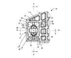
先ず、図1〜図5に、本発明の一実施形態であるクランプ部を備えた取付部品としての電気接続箱10の要部が示されている。この電気接続箱10は、自動車の電装系においてリレーボックス等として用いられるものであり、後述する車体パネル等の支持パネル30に取り付けられてエンジンルーム等に配設されるものである。本実施形態では、図1に示される電気接続箱10のロアケースにおいて、支持パネル30への取付部11が一体的に設けられており、この取付部11に対して、クランプ部12が突設されている。そして、クランプ部12が支持パネル30に設けられた貫通穴32(図6参照)に圧入されて係止固定されることにより、電気接続箱10が支持パネル30に固定的に取り付けられるようになっている。
First, the principal part of the
より詳しくは、図1に示される電気接続箱10のロアケースは、合成樹脂製とされており、その外周縁部に取付部11が一体的に設けられている。この取付部11の支持パネル30への取付面となる外面11a(図1中の上面)には、取付部11の支持パネル30への取付方向において、外面11aから外方に突出する合成樹脂製のクランプ部12が一体形成されている。
More specifically, the lower case of the
図4に明示されているように、このクランプ部12は、取付部11の外面11aから相互に離隔して並列状態で突出する一対の支持脚部14,14を備えている。一対の支持脚部14,14は略長方形断面でストレートに突出する薄肉の平板形状を有しており、各支持脚部14の基端部14aが、取付部11に対して一体的に連結されている。なお、図3及び図5から明らかなように、各支持脚部14の幅寸法は、基端部14aにおいて大きくされており、各支持脚部14の弾性変形に際して応力の集中する基端部14aの強度や耐久性の確保が図られている。
As clearly shown in FIG. 4, the
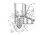
一方、一対の支持脚部14,14の突出先端部14b,14bには、それぞれ薄肉の略矩形平板形状を有する一対の係止突片16,16が一体的に設けられている。すなわち、一対の係止突片16,16は、それらの一端側となる基端部16a,16aにおいて、一対の支持脚部14,14の突出先端部14b,14bと一体的に連結されており、一対の支持脚部14,14の突出方向と同じ方向に突出するにつれ、互いに接近するように延び出している。そして、一対の係止突片16,16は、それらの他端側となる先端部16b,16bにおいて、相互に一体的に連結されている。
On the other hand, a pair of locking
これにより、一対の支持脚部14,14の突出先端部14b,14bに一体的に連結されてそれらの突出方向に先細状に突出する係止突部18が、一対の係止突片16,16によって、構成されているのである。なお、係止突部18の基端部を構成する一対の係止突片16,16の基端部16a,16aは、一対の支持脚部14,14の突出方向に直交する方向、すなわち、一対の支持脚部14,14の対向方向(図4中左右方向)において、両支持脚部14,14の外面よりも外方に突出されている。
As a result, the locking
そして、一対の支持脚部14,14の対向方向(図4中左右方向)において、
係止突部18の最大幅寸法となる基端部16a,16a間の幅寸法L1よりも、一対の支持脚部14,14の取付部11の外面11aからの突出長さ寸法L2の方が、大きくされている。これにより、一対の支持脚部14,14の取付部11からの突出長さを充分に大きく確保することができて、一対の支持脚部14,14ひいては一対の係止突片16,16の撓み変形が容易に許容されるようになっている。
And in the opposing direction (left-right direction in FIG. 4) of a pair of
The protrusion length dimension L2 from the
また、一対の支持脚部14,14の対向面間には、一対の係止突片16,16の先端部16b,16bの連結部となる係止突部18の突出端部から、取付部11に向かって延び出す補強リブ20が一体的に設けられている。この補強リブ20は、各支持脚部14,14からそれぞれ所定隙間を隔てて、離隔した状態で設けられている。図3〜図5に示されているように、補強リブ20は、一対の支持脚部14,14よりも充分に大きな幅寸法を有する薄肉の平板形状を有しており、その幅方向両側端部が一対の支持脚部14,14の側縁部よりも両側に大きく突出している。
Further, between the opposed surfaces of the pair of
そして、補強リブ20の幅方向両側端部が、取付部11の外面11aから突出する一対の厚肉部22,22に対して一体的に連結されている。このように、一対の厚肉部22,22を介して補強リブ20が取付部11に一体的に連結されて支持されることによって、補強リブ20の強度や耐久性の確保が図られている。本実施形態では、一対の厚肉部22,22の外周面形状が、後述する貫通穴32の形状に対応した円弧状となるように、各厚肉部22が略半円形断面で突出形成されている(図2及び図9参照)。なお、厚肉部22の形状は、貫通穴32の形状等に応じて任意に設定可能である。
Then, both end portions in the width direction of the reinforcing
また、図4及び図5に示されているように、係止突部18の突出端部から取付部11に向かう補強リブ20の延出長さは、取付部11に至らない長さとされている。これにより、補強リブ20の延出端部は、取付部11に連結しない自由端とされている。また、図1及び図5から明らかなように、補強リブ20の係止突部18側の端部は、係止突部18の先端側に向かって次第に幅寸法が小さくなるテーパ状部23とされている。これにより、クランプ部12を支持パネル30の貫通穴32に圧入する際に、補強リブ20が貫通穴32の周縁に引っ掛かる等の不具合が回避されて、スムーズな圧入作業が行われるようになっている。
As shown in FIGS. 4 and 5, the extension length of the reinforcing
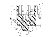
また、クランプ部12は、一対の支持脚部14,14や補強リブ20の両側端部に設けられた一対の厚肉部22,22の周囲に位置して、それらから隙間を隔てて配設された当接突部28を含んで構成されている。当接突部28は、略矩形枠体断面で取付部11の外面11aから、支持脚部14,14と同じ方向に向かって平行に突出している。そして、取付部11の外面11aからの当接突部28の突出長さは、各支持脚部14の外面11aからの突出長さよりも所定寸法小さくされている。なお、当接突部28の突出長さは、当接突部28と支持脚部14,14の突出先端部14b,14bに設けられた係止突部18の基端部16a,16aとの間で、支持パネル30が挟持され得るように適宜に設定される(図7参照)。
The
このように、本実施形態においては、クランプ部12を構成する一対の支持脚部14,14、および当接突部28が取付部11の外面11aに突設されて一体形成されている。また、一対の支持脚部14,14の突出先端部14b,14bには、一対の係止突片16,16により構成される係止突部18が一体的に設けられており、係止突部18の突出端部から取付部11に向かって延出する補強リブ20が併せて一体形成されている。そして、補強リブ20と一対の支持脚部14,14の対向面間および各支持脚部14と当接突部28の対向面間に隙間が設けられていることにより、一対の支持脚部14,14の弾性変形が阻害されないようになっている。なお、成形型を用いた合成樹脂の射出成形により、一対の支持脚部14,14の突出先端部14b,14bに係止突部18を一体形成することを可能とするために、図3に示す取付部11の内面11b(図1中の下面)には、一対の支持脚部14,14間の隙間と、各支持脚部14と当接突部28の間の隙間にそれぞれ連通する型抜穴24,26,26が開口形成されている。
As described above, in the present embodiment, the pair of
このような構造とされた、本実施形態にかかる電気接続箱10は、クランプ部12や図示しないボルト等の固定手段を用いて、支持パネル30に固定的に取り付けられることとなる。以下、図6〜図9に基づき電気接続箱10のクランプ部12を用いた支持パネル30への取り付け工程について説明する。
The
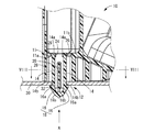
先ず、図6に示されるように、電気接続箱10の取付部11の外面11a側を、支持パネル30の前面側に対向させて、取付部11の外面11aに突設されたクランプ部12の係止突部18を、支持パネル30に設けられた貫通穴32に押し込むようにして圧入する。その際、係止突部18を構成する一対の係止突片16,16やそれらの基端部16a,16aに一体的に連結された一対の支持脚部14,14が、それらの間に設けられた隙間を利用して相互に接近する方向に撓み変形される。これにより、係止突部18の外形寸法が貫通穴32を挿通可能な程度に小さくされる。なお、本実施形態では、一対の係止突片16,16や一対の支持脚部14,14の間に補強リブ20が配設されていることから、各係止突片16や各支持脚部14の過大な撓み変形が、それらの補強リブ20への当接により阻止されるようになっている。それ故、クランプ部12の貫通穴32への圧入時に、各係止突片16や各支持脚部14が過大な変形による応力の集中等により破損等することが未然に防止され得る。
First, as shown in FIG. 6, the
そして、図7〜図9に示されるように、クランプ部12の係止突部18が貫通穴32を通過すると、一対の係止突片16,16や一対の支持脚部14,14が相互に離隔する方向に弾性復帰して、一対の係止突片16,16の基端部16a,16aが、支持パネル30の後面側で、貫通穴32の周縁部に当接される。一方、支持パネル30の前面側では、貫通穴32から離隔した位置において、当接突部28の突出先端面が支持パネル30に当接されている。これにより、係止突部18の基端部を構成する一対の係止突片16,16の基端部16a,16aと当接突部28の突出先端面との間で、支持パネル30が挟持されて、クランプ部12が貫通穴32に対して係止固定されている。
As shown in FIGS. 7 to 9, when the locking
本実施形態に従う構造とされたクランプ部12を備えた電気接続箱10によれば、係止突部18を構成する一対の係止突片16,16の基端部16a,16aが、相互に離隔して並列状態で突設された一対の支持脚部14,14を介して取付部11に一体的に連結されている。従って、係止突部18が支持パネル30の貫通穴32に圧入される際には、一対の係止突片16,16や一対の支持脚部14,14が、それらの間に設けられた隙間を利用して相互に接近する方向に容易に撓み変形されることとなる。それ故、クランプ部12の貫通穴32への圧入力の低減を図ることができる。
According to the
また、ひとたび係止突部18が貫通穴32を通過してもとの形状に弾性復帰すると、支持パネル30の後面側で貫通穴32の周縁部に一対の係止突片16,16の基端部16a,16aが当接することとなる。その際、一対の係止突片16,16の基端部16a,16aが、一対の支持脚部14,14を介して取付部11に剛結されていることから、一対の係止突片16,16の基端部16a,16aの剛性が有利に確保されて、貫通穴32の周縁部に対する基端部16a,16aの当接状態が安定して保持される。それ故、貫通穴32の周縁部に当接された係止突部18が、従来の片持ち梁構造のクランプ部の如く、弾性変形して固定力が低下する不具合を有利に回避することができる。これにより、係止突部18と当接突部28間の支持パネル30の挟み込みによる固定力を安定して維持することができる。
Further, once the locking
このように、本実施形態では、一対の係止突片16,16や一対の支持脚部14,14が、それらの間に設けられた隙間を利用して相互に接近する方向に容易に撓み変形されることにより、クランプ部12の圧入力の低減を図ると共に、一対の係止突片16,16を一対の支持脚部14,14を介して取付部11に一体的に連結することにより、係止突部18の剛性の向上およびクランプ部12による固定力の向上を図ったものである。それ故、固定力の向上のために係止突部18を厚肉化したり、圧入力の低減のために係止突部18の傾斜角度を必要以上に小さくする必要がなく、貫通穴32からの係止突部18の突出量を小さく抑えることが可能となる。
Thus, in this embodiment, a pair of latching
また、一対の支持脚部14,14間の隙間を利用して補強リブ20が配設されており、この補強リブ20によっても係止突部18が支持されている。これにより、貫通穴32への圧入時に係止突部18や一対の支持脚部14,14に加えられる圧入力を補強リブ20によっても分担して受け持つことができ、クランプ部12全体の強度や耐久性の向上が図られている。
Further, a reinforcing
そして、一対の係止突片16,16および一対の支持脚部14,14と、補強リブ20の間には、隙間が確保されており、各係止突片16や支持脚部14の必要な撓み変形が補強リブ20により制限されないようになっている。それ故、係止突部18の貫通穴32への圧入力の低減が有利に図られている。また、各係止突片16や支持脚部14の補強リブ20への当接により、各係止突片16や支持脚部14の過度の弾性変形が阻止されることから、クランプ部12の耐久性の向上が図られている。
A gap is secured between the pair of locking
さらに、補強リブ20の係止突部18の突出端部からの突出長さは、取付部11に至らない長さとされており、補強リブ20の延出端部が自由端とされている。これにより、係止突部18を支持パネル30の貫通穴32に圧入する際の各係止突片16や支持脚部14の撓み変形がし易くされており、補強リブ20によりクランプ部12を補強しつつ、クランプ部12の圧入力の充分な低減が図られている。
Further, the protruding length of the reinforcing
加えて、一対の支持脚部14,14の取付部11の外面11aからの突出長さ寸法L2が、一対の支持脚部14,14の突出方向に対向する方向において、係止突部18の最大幅寸法となる一対の係止突片16,16の基端部16a,16a間の幅寸法L1よりも大きくされている。これにより、一対の支持脚部14,14の取付部11からの突出長さを充分に大きく確保することができて、一対の支持脚部14,14ひいては一対の係止突片16,16の撓み変形を一層容易に許容することができる。従って、一対の係止突片16,16の基端部16a,16aを一対の支持脚部14,14を介して取付部11に一体的に連結しても、係止突部18の貫通穴32への圧入を容易になすことができ、クランプ部12の圧入力の低減と固定力の向上の両立を有利に達成することができる。
In addition, the protrusion length dimension L2 from the
以上、本発明の実施形態について詳述したが、本発明はその具体的な記載によって限定されない。例えば、前記実施形態においては、補強リブ20の延出端部が自由端とされていたが、要求される強度等によっては、補強リブ20の突出端部を取付部11に剛結させて、クランプ部12の強度を確保するようにしてもよい。
As mentioned above, although embodiment of this invention was explained in full detail, this invention is not limited by the specific description. For example, in the above-described embodiment, the extending end of the reinforcing
また、一対の支持脚部14,14や一対の係止突片16,16等の形状は任意に設定されるものであり、例えば、貫通穴32の形状に応じて、各支持脚部14の断面形状を半円形断面としたり、各係止突片16の形状を、基端部16aに向かって幅寸法が大きくなる形状として、貫通穴32との当接面積をより大きく確保するようにしてもよい。
In addition, the shapes of the pair of
前記実施形態では、クランプ部12を備えた電気接続箱10に本発明を適用した例について詳述したが、本発明は、支持パネルの貫通穴に圧入されるクランプ部を備えた取付部品であれば、電気接続箱の他、コネクタブロックや、ワイヤハーネス支持具等のあらゆる機器類に適用可能である。
In the above-described embodiment, the example in which the present invention is applied to the
10:電気接続箱(取付部品)、11:取付部、12:クランプ部、14:一対の支持脚部、14b:突出先端部、16a:基端部、18:係止突部、20:補強リブ、28:当接突部、30:支持パネル、32:貫通穴 10: Electrical junction box (attachment part), 11: Attachment part, 12: Clamp part, 14: A pair of support leg part, 14b: Protruding tip part, 16a: Base end part, 18: Locking protrusion part, 20: Reinforcement Rib, 28: contact protrusion, 30: support panel, 32: through hole
Claims (3)
前記クランプ部が、前記取付部から相互に離隔して並列状態で突出する一対の支持脚部と、前記一対の支持脚部の周囲に位置して該支持脚部よりも突出長さが小さくされた当接突部と、前記一対の支持脚部の各突出先端部に一体的に連結されると共に前記一対の支持脚部の突出方向に先細状に突出する係止突部とを備えている一方、
前記係止突部の基端部が、前記一対の支持脚部の突出方向に直交する方向で、前記一対の支持脚部の外面よりも外方に突出されており、
前記係止突部が前記貫通穴に圧入されることにより、前記係止突部の前記基端部と前記当接突部との間で前記支持パネルが挟持されて、前記クランプ部が前記貫通穴に係止固定されるようになっている、
ことを特徴とするクランプ部を備えた取付部品。 A clamp portion made of synthetic resin protruding from a mounting portion to the support panel is provided, and the support is provided by press-fitting and locking the clamp portion into a through hole provided in the support panel. In the mounting part with the clamp part, which can be attached to the panel,
The clamp portion is spaced apart from the mounting portion and protrudes in a parallel state, and is positioned around the pair of support leg portions so that the protruding length is smaller than the support leg portion. Contact protrusions, and locking protrusions that are integrally connected to the protruding tip portions of the pair of support leg portions and protrude in a tapered shape in the protruding direction of the pair of support leg portions. on the other hand,
The base end portion of the locking projection protrudes outward from the outer surface of the pair of support legs in a direction orthogonal to the protruding direction of the pair of support legs.
When the locking projection is press-fitted into the through hole, the support panel is sandwiched between the base end portion of the locking projection and the abutting projection, and the clamp portion passes through the through-hole. It is designed to be locked and fixed in the hole,
A mounting part having a clamp part characterized by the above.
Priority Applications (1)
| Application Number | Priority Date | Filing Date | Title |
|---|---|---|---|
| JP2010149249A JP2012013132A (en) | 2010-06-30 | 2010-06-30 | Installing part equipped with clamp part |
Applications Claiming Priority (1)
| Application Number | Priority Date | Filing Date | Title |
|---|---|---|---|
| JP2010149249A JP2012013132A (en) | 2010-06-30 | 2010-06-30 | Installing part equipped with clamp part |
Publications (1)
| Publication Number | Publication Date |
|---|---|
| JP2012013132A true JP2012013132A (en) | 2012-01-19 |
Family
ID=45599809
Family Applications (1)
| Application Number | Title | Priority Date | Filing Date |
|---|---|---|---|
| JP2010149249A Abandoned JP2012013132A (en) | 2010-06-30 | 2010-06-30 | Installing part equipped with clamp part |
Country Status (1)
| Country | Link |
|---|---|
| JP (1) | JP2012013132A (en) |
Citations (2)
| Publication number | Priority date | Publication date | Assignee | Title |
|---|---|---|---|---|
| JPS5889604U (en) * | 1981-12-12 | 1983-06-17 | ソニー株式会社 | Fastener |
| JP2006200610A (en) * | 2005-01-19 | 2006-08-03 | Toyota Motor Corp | Fastening structure of resin member |
-
2010
- 2010-06-30 JP JP2010149249A patent/JP2012013132A/en not_active Abandoned
Patent Citations (2)
| Publication number | Priority date | Publication date | Assignee | Title |
|---|---|---|---|---|
| JPS5889604U (en) * | 1981-12-12 | 1983-06-17 | ソニー株式会社 | Fastener |
| JP2006200610A (en) * | 2005-01-19 | 2006-08-03 | Toyota Motor Corp | Fastening structure of resin member |
Similar Documents
| Publication | Publication Date | Title |
|---|---|---|
| EP2749778B1 (en) | Clip | |
| JP6684675B2 (en) | Assembly type vehicle parts | |
| JP5107283B2 (en) | clip | |
| US10227025B2 (en) | Resin cover and vehicle seat having resin cover | |
| JP4605112B2 (en) | Electrical junction box | |
| US11611165B2 (en) | Connector | |
| JP2005317363A (en) | Connector | |
| JPWO2015008551A1 (en) | Reinforcing leaf spring for plastic clips | |
| JP2008190705A (en) | Clamp | |
| JP2012013132A (en) | Installing part equipped with clamp part | |
| JP4336956B2 (en) | Parts mounting clip | |
| JP6350876B2 (en) | connector | |
| JP6281707B2 (en) | Electrical junction box | |
| JP2017228384A (en) | Connector Holder | |
| JP7081978B2 (en) | Protector and protector mounting structure | |
| JP2022061073A (en) | Terminal unit | |
| JP6541627B2 (en) | Terminal block | |
| JP2007143273A (en) | Attachment tool | |
| KR200448593Y1 (en) | Connector | |
| JP6464429B2 (en) | Holder and holder mounting structure | |
| JP7436303B2 (en) | joint connector | |
| JP6093645B2 (en) | Joint connector | |
| JP5574278B2 (en) | Automotive parts | |
| JP6062307B2 (en) | Parts matching part structure | |
| JP5186288B2 (en) | Wire harness retaining clip |
Legal Events
| Date | Code | Title | Description |
|---|---|---|---|
| A621 | Written request for application examination |
Free format text: JAPANESE INTERMEDIATE CODE: A621 Effective date: 20130129 |
|
| A977 | Report on retrieval |
Free format text: JAPANESE INTERMEDIATE CODE: A971007 Effective date: 20130909 |
|
| A131 | Notification of reasons for refusal |
Free format text: JAPANESE INTERMEDIATE CODE: A131 Effective date: 20131021 |
|
| A762 | Written abandonment of application |
Free format text: JAPANESE INTERMEDIATE CODE: A762 Effective date: 20131128 |