JP2012005244A - On-vehicle electronic control unit device - Google Patents
On-vehicle electronic control unit device Download PDFInfo
- Publication number
- JP2012005244A JP2012005244A JP2010138143A JP2010138143A JP2012005244A JP 2012005244 A JP2012005244 A JP 2012005244A JP 2010138143 A JP2010138143 A JP 2010138143A JP 2010138143 A JP2010138143 A JP 2010138143A JP 2012005244 A JP2012005244 A JP 2012005244A
- Authority
- JP
- Japan
- Prior art keywords
- vehicle
- housing
- control unit
- case
- housing case
- Prior art date
- Legal status (The legal status is an assumption and is not a legal conclusion. Google has not performed a legal analysis and makes no representation as to the accuracy of the status listed.)
- Pending
Links
Images


Landscapes
- Structure Of Printed Boards (AREA)
- Mounting Of Printed Circuit Boards And The Like (AREA)
- Connection Or Junction Boxes (AREA)
- Shielding Devices Or Components To Electric Or Magnetic Fields (AREA)
Abstract
Description
本発明は、車両衝突時に乗員を保護するエアバッグ等の乗員保護装置に用いられる車載用電子制御ユニット装置に関し、特に、車両衝突時に電子制御ユニットの筺体内に配設されるプリント基板上の電子部品を外部ノイズから保護することが可能な車載用電子制御ユニット装置に関する。 The present invention relates to an in-vehicle electronic control unit device used for an occupant protection device such as an air bag for protecting an occupant in the event of a vehicle collision, and more particularly, to an electronic device on a printed circuit board that is disposed in a housing of the electronic control unit in the event of a vehicle collision. The present invention relates to an on-vehicle electronic control unit device that can protect components from external noise.
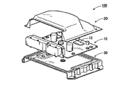
従来、この種の車載用電子制御ユニット装置として、特許文献1に記載の電子装置用筺体がある。図1に示すように、その筺体100は、車両の電子制御ユニットの装置であって、電子部品12が実装された回路基板10を収納する金属製のベース30とケース20とからなり、図示せぬ車両等の被取付体に取付けられる。このような構成においては、電子部品12がケース20及びベース30による金属筺体でシールドされているので、電子部品12を外部のノイズから保護することが出来る。
Conventionally, as this type of vehicle-mounted electronic control unit device, there is a housing for electronic devices described in Patent Document 1. As shown in FIG. 1, the
ところで、近年では車載用電子制御ユニット装置全体の小型軽量化を図るため、そのケースを樹脂製としている。しかし、上記の特許文献1において、ケース20が樹脂製である場合、ケース内の回路基板10に実装された電子部品12が外部ノイズの影響を受け、例えば電子部品12の1つであるCPU(中央処理装置)が誤作動する等の問題が生じる。
By the way, in recent years, the case is made of resin in order to reduce the size and weight of the on-vehicle electronic control unit device as a whole. However, in the above Patent Document 1, when the
本発明は、このような事情に鑑みてなされたものであり、樹脂ケース内に密閉状に収納された電子部品を外部ノイズの影響を受けないように保護することができる車載用電子制御ユニット装置を提供することを目的とする。 The present invention has been made in view of such circumstances, and an on-vehicle electronic control unit device capable of protecting an electronic component housed in a sealed state in a resin case so as not to be affected by external noise. The purpose is to provide.
上記目的を達成するためになされた請求項1に記載の発明は、下方が開口した箱型で樹脂製の筺体ケースと、この筺体ケースの開口から当該筺体ケース内に収納され、電子部品が実装された多層基板と、前記筺体ケースの開口を蓋する形状を成す金属製の筺体カバーとを有し、前記筺体ケース内に前記基板を収納して前記筺体カバーで当該基板を当該筺体ケースとの間で挟持し、前記開口が蓋閉される状態に固定する車載用電子制御ユニット装置において、前記多層基板は、前記筺体ケース側を向く表面全面又は内層面全面にアース層が形成され、前記筺体カバー側を向く裏面に前記電子部品が実装されている。 In order to achieve the above object, the invention according to claim 1 is a box-shaped resin case having a lower opening, and is housed in the case from the opening of the case so that an electronic component is mounted. A multi-layered substrate and a metal housing cover configured to cover the opening of the housing case, the substrate is housed in the housing case, and the substrate is covered with the housing case by the housing cover. In the on-vehicle electronic control unit device that is sandwiched between and fixed in a state in which the opening is closed, the multilayer substrate has a ground layer formed on the entire surface or the entire inner surface facing the housing case side, and the housing The electronic component is mounted on the back surface facing the cover side.
この構成によれば、樹脂ケース内に密閉状に収納された電子部品が、多層基板の表面全面又は内層全面に形成されたアース層と、金属製の筺体カバーとで囲まれて外部と遮蔽状態に収納されるので、電子部品を外部ノイズの影響を受けないように保護することができる。 According to this configuration, the electronic component housed in the resin case in a hermetically sealed state is surrounded by the ground layer formed on the entire surface of the multilayer substrate or the entire inner layer and the metal housing cover, and is shielded from the outside. Thus, the electronic component can be protected from being affected by external noise.
請求項2に記載の発明は、前記多層基板には車両の加速度を測定する加速度センサが実装され、前記電子部品は前記加速度センサの情報から車両の衝突を判定するマイコンであることを特徴とする。 The invention according to claim 2 is characterized in that an acceleration sensor for measuring the acceleration of the vehicle is mounted on the multilayer board, and the electronic component is a microcomputer that determines a collision of the vehicle from information of the acceleration sensor. .
この構成によれば、外部ノイズの影響を受ける電子部品やセンサ部品のみが多層基板の裏面に実装されるので、多層基板の表面及び裏面を有効活用することができる。 According to this configuration, only the electronic components and sensor components that are affected by external noise are mounted on the back surface of the multilayer substrate, so that the front and back surfaces of the multilayer substrate can be used effectively.
以下、本発明の実施形態を、図面を参照して説明する。但し、本明細書中の全図において相互に対応する部分には同一符号を付し、重複部分においては後述での説明を適時省略する。 Embodiments of the present invention will be described below with reference to the drawings. However, parts corresponding to each other in all the drawings in this specification are denoted by the same reference numerals, and description of the overlapping parts will be omitted as appropriate.
図2は、本発明の実施形態に係る車載用電子制御ユニット装置の外観及び内部の一部を透視した構成を示す斜視図である。図3は、図2に示す車載用電子制御ユニット装置を分解した構成を示す斜視図である。 FIG. 2 is a perspective view showing the configuration of the exterior and part of the interior of the in-vehicle electronic control unit device according to the embodiment of the present invention. FIG. 3 is a perspective view showing an exploded configuration of the in-vehicle electronic control unit device shown in FIG.
図2に示す車載用電子制御ユニット装置(ECU)50は、図3に示すように、下方が開口した箱型で樹脂製の筺体ケース11と、筺体ケース11の開口からケース内に挿入されて固定され、複数の板状の配線層が一体に組み合わされた多層基板51と、筺体ケース11の開口に固定され当該開口を蓋する鉄等の金属板である筺体カバー13とから構成されている。
As shown in FIG. 3, an in-vehicle electronic control unit device (ECU) 50 shown in FIG. 2 is a box-
筺体ケース11は、ケース内の四隅に柱状部材11aが固定され、この柱状部材11aの開口側に凹部が形成され、この凹部にネジ15を螺合して固定するインサートナット11bが嵌合固定されている。更に筺体ケース11の一側面には、多層基板51に実装された箱型のコネクタ16を嵌合する四角形状の切り欠き部11cが形成されている。
In the
多層基板51には、四つ角部分にネジ15を螺合して筺体ケース11と筺体カバー13との間に当該多層基板51を固定するための貫通したネジ穴12aが設けられている。各ネジ穴12aは、筺体ケース11の各インサートナット11bの位置に対応している。
The
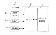
また、多層基板51の上面及び裏面には、図4に示すECU回路21が構成されており、これは、車両の加速度を検出する加速度センサ22と、データを記憶する記憶装置23と、外部IF(インターフェイス)25と、これら加速度センサ22、記憶装置23及び外部IF25が接続されたマイコン24と、このマイコン24で制御され、図示せぬエアバッグを駆動するエアバッグ駆動回路26とを備えて構成されている。各外部IF(インターフェイス)25a〜25nは、コネクタ16に組み合わされている。マイコン24は、外部IF25a〜25nに接続された図示せぬ加速度センサや、加速度センサ22で検出された加速度に応じて車両の衝突と判定した場合、図示せぬエアバッグを開放する制御などを行うと共に、記憶装置23に車両衝突時の前後の車両速度を含む車両情報などを記憶する制御を行う。
Further, an
筺体カバー13には、多層基板51の各ネジ穴12aと対応する位置にネジ15を螺合するネジ穴13aが形成され、更に、互いに対向する2辺(又は縁)に凸状に突き出た3つの取付部13b1,13b2,13b3が設けられている。これは、一辺に2つの取付部13b1及び13b3が設けられ、他辺に1つの取付部13b2が設けられている。これら取付部13b1〜13b3は、車両の所定位置にECU50を固定するためのものである。
The
このような筺体ケース11、多層基板51及び筺体カバー13を組み立ててECU50を構成する場合、筺体ケース11と筺体カバー13との間に多層基板51を挟み、筺体ケース11の各インサートナット11bの位置に、多層基板51の各ネジ穴12a及び筺体カバー13の各ネジ穴13cを合わせて、筺体カバー13の下方側からネジ15を螺合して固定する。これによって形成されたECU50は、車両に取付部13b1〜13b3を介してネジ固定される。この固定されたECU50は、図2に示すように、コネクタ16の搭載側と反対側が車両前方側となり、コネクタ16の搭載側が車両後方側となる。更に、2つの取付部13b1,13b3が設けられている側が車両右側、1つの取付部13b2が設けられている側が車両左側であり、筺体ケース11が上方側であるとする。
When the ECU 50 is configured by assembling the
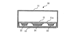
このような構成のECU50における本実施形態の特徴は、図2に示すA1−A2断面図である図5に示すように、多層基板51の内層全面にアース層51aを設け、この多層基板51の筺体カバー13側を向く裏面に記憶装置23及びマイコン24などの電子部品と、加速度センサ22などのセンサ部品とを実装し、これら実装部品が多層基板51と筺体カバー13との間に外部と遮蔽状態に収納される構成とした点にある。
The feature of the present embodiment in the
このような本実施形態のECU10においては、外部ノイズの影響を受けて誤動作等が生じる記憶装置23、マイコン24及び加速度センサ22が、多層基板51の内層全面に形成されたアース層51aと、この多層基板51の裏面側に配置される金属製の筺体カバー13とで囲まれて外部と遮蔽状態に収納されるので、外部ノイズの影響を受けなくなる。
In the
また、マイコン24のみが、アース層51aと筺体カバー13とで囲まれて外部と遮蔽状態に収納されるようにしてもよく、更には、ECU回路21を構成する全ての電子部品が、アース層51aと筺体カバー13とで囲まれて外部と遮蔽状態に収納されるようにしても良い。更に、アース層51aは、多層基板51の筺体ケース11側を向く表面全面に形成しても良い。このような構成によって、筺体ケース11内に密閉状に収納された電子部品を外部ノイズの影響を受けないように保護することができる。
Further, only the
11 筺体ケース
11a 柱状部材
11c 切り欠き部
11b インサートナット
12a ネジ穴
13 筺体カバー
13b1,13b2,13b3 取付部
15 ネジ
16 コネクタ
21 ECU回路
22 加速度センサ
23 記憶装置
24 マイコン
25a〜25n 外部IF(インターフェイス)
50 車載用電子制御ユニット装置(ECU)
51 多層基板
DESCRIPTION OF
50 On-vehicle electronic control unit (ECU)
51 multilayer boards
Claims (2)
前記多層基板は、前記筺体ケース側を向く表面全面又は内層面全面にアース層が形成され、前記筺体カバー側を向く裏面に前記電子部品が実装されていることを特徴とする車載用電子制御ユニット装置。 A box-shaped resin case with an opening at the bottom, a multilayer board that is housed in the housing case from the opening of the housing case and on which electronic components are mounted, and a metal that covers the opening of the housing case An in-vehicle housing that has a housing cover made of a material, houses the substrate in the housing case, holds the substrate between the housing case and the housing case, and fixes the opening in a closed state. In the electronic control unit device,
The in-vehicle electronic control unit, wherein the multilayer substrate has a ground layer formed on the entire front surface or inner layer surface facing the housing case side, and the electronic component is mounted on the back surface facing the housing cover side. apparatus.
Priority Applications (1)
| Application Number | Priority Date | Filing Date | Title |
|---|---|---|---|
| JP2010138143A JP2012005244A (en) | 2010-06-17 | 2010-06-17 | On-vehicle electronic control unit device |
Applications Claiming Priority (1)
| Application Number | Priority Date | Filing Date | Title |
|---|---|---|---|
| JP2010138143A JP2012005244A (en) | 2010-06-17 | 2010-06-17 | On-vehicle electronic control unit device |
Publications (1)
| Publication Number | Publication Date |
|---|---|
| JP2012005244A true JP2012005244A (en) | 2012-01-05 |
Family
ID=45536588
Family Applications (1)
| Application Number | Title | Priority Date | Filing Date |
|---|---|---|---|
| JP2010138143A Pending JP2012005244A (en) | 2010-06-17 | 2010-06-17 | On-vehicle electronic control unit device |
Country Status (1)
| Country | Link |
|---|---|
| JP (1) | JP2012005244A (en) |
Cited By (5)
| Publication number | Priority date | Publication date | Assignee | Title |
|---|---|---|---|---|
| WO2013129982A1 (en) | 2012-03-01 | 2013-09-06 | Autoliv Development Ab | An electronic unit with a pcb and two housing parts |
| WO2013140884A1 (en) * | 2012-03-19 | 2013-09-26 | 日立オートモティブシステムズ株式会社 | Electronic control device |
| WO2014069644A1 (en) * | 2012-11-05 | 2014-05-08 | オートリブ ディベロップメント エービー | On-board circuit substrate-equipped apparatus |
| CN106471874A (en) * | 2014-06-25 | 2017-03-01 | 罗伯特·博世有限公司 | Device for operator's protective equipment and the method for manufacturing the device for operator's protective equipment |
| US20170290140A1 (en) * | 2016-04-05 | 2017-10-05 | Harman International Industries, Inc. | Electromagnetic shield for an electronic device |
-
2010
- 2010-06-17 JP JP2010138143A patent/JP2012005244A/en active Pending
Cited By (11)
| Publication number | Priority date | Publication date | Assignee | Title |
|---|---|---|---|---|
| WO2013129982A1 (en) | 2012-03-01 | 2013-09-06 | Autoliv Development Ab | An electronic unit with a pcb and two housing parts |
| JP2015508942A (en) * | 2012-03-01 | 2015-03-23 | オートリブ ディベロップメント エービー | Electronic unit having a PCB and two housing parts |
| WO2013140884A1 (en) * | 2012-03-19 | 2013-09-26 | 日立オートモティブシステムズ株式会社 | Electronic control device |
| JP2013197223A (en) * | 2012-03-19 | 2013-09-30 | Hitachi Automotive Systems Ltd | Electronic control device |
| EP2830405A4 (en) * | 2012-03-19 | 2015-11-25 | Hitachi Automotive Systems Ltd | Electronic control device |
| WO2014069644A1 (en) * | 2012-11-05 | 2014-05-08 | オートリブ ディベロップメント エービー | On-board circuit substrate-equipped apparatus |
| DE212013000221U1 (en) | 2012-11-05 | 2015-06-10 | Autoliv Development Ab | Board installation device for arrangement in vehicles |
| CN106471874A (en) * | 2014-06-25 | 2017-03-01 | 罗伯特·博世有限公司 | Device for operator's protective equipment and the method for manufacturing the device for operator's protective equipment |
| US10188018B2 (en) | 2014-06-25 | 2019-01-22 | Robert Bosch Gmbh | Device for controlling personal protection means and method for producing a device for controlling personal protection means |
| US20170290140A1 (en) * | 2016-04-05 | 2017-10-05 | Harman International Industries, Inc. | Electromagnetic shield for an electronic device |
| US10462895B2 (en) * | 2016-04-05 | 2019-10-29 | Harman International Industries, Incorporated | Electromagnetic shield for an electronic device |
Similar Documents
| Publication | Publication Date | Title |
|---|---|---|
| JP5110130B2 (en) | In-vehicle electronic control unit housing | |
| JP2012005244A (en) | On-vehicle electronic control unit device | |
| JP2012001105A (en) | In-vehicle electronic control unit device | |
| JP6012547B2 (en) | Case for occupant protection device control unit storage | |
| JP2002308021A (en) | On-vehicle electronic apparatus | |
| JP2010167816A (en) | Casing for on-vehicle electronic control unit | |
| JP2017162854A (en) | Electronic controller | |
| JP2008193108A (en) | Electronic control device | |
| JP2018087916A (en) | Imaging device | |
| JP6165107B2 (en) | Car electronics | |
| JP4909774B2 (en) | Electronic devices and personal computers | |
| JP5951457B2 (en) | Mirror device | |
| JP6567079B2 (en) | Electronics | |
| JP2000105628A (en) | Electronic equipment with buffer structure | |
| JP2005100570A (en) | Electronic device for vehicle | |
| WO2015064203A1 (en) | Vehicle safety device control unit | |
| JP2013206592A (en) | Electronic device | |
| JP5968266B2 (en) | Display device | |
| JP5083270B2 (en) | Electronics | |
| JP4859048B2 (en) | Electromagnetic shielding case | |
| JP6618325B2 (en) | Printed circuit board unit and electronic device | |
| JP4843331B2 (en) | Electrical component mounting structure | |
| JP4264023B2 (en) | Car equipment | |
| JP5916252B2 (en) | Electronic device with shock absorbing bumper and shock detection method acting on electronic device | |
| JP6436070B2 (en) | Electronic equipment mounting box for vehicles |