JP2012003019A - Image forming apparatus - Google Patents
Image forming apparatus Download PDFInfo
- Publication number
- JP2012003019A JP2012003019A JP2010137645A JP2010137645A JP2012003019A JP 2012003019 A JP2012003019 A JP 2012003019A JP 2010137645 A JP2010137645 A JP 2010137645A JP 2010137645 A JP2010137645 A JP 2010137645A JP 2012003019 A JP2012003019 A JP 2012003019A
- Authority
- JP
- Japan
- Prior art keywords
- gear
- driven
- drive
- pitch circle
- image forming
- Prior art date
- Legal status (The legal status is an assumption and is not a legal conclusion. Google has not performed a legal analysis and makes no representation as to the accuracy of the status listed.)
- Withdrawn
Links
- 230000005540 biological transmission Effects 0.000 claims description 19
- 230000015572 biosynthetic process Effects 0.000 claims description 8
- 238000006073 displacement reaction Methods 0.000 description 27
- 238000012546 transfer Methods 0.000 description 25
- 238000005192 partition Methods 0.000 description 11
- 230000036544 posture Effects 0.000 description 10
- 238000013459 approach Methods 0.000 description 7
- 238000000034 method Methods 0.000 description 7
- 238000010586 diagram Methods 0.000 description 6
- 238000013016 damping Methods 0.000 description 5
- 238000000465 moulding Methods 0.000 description 5
- 239000003086 colorant Substances 0.000 description 4
- 238000012545 processing Methods 0.000 description 4
- 230000006866 deterioration Effects 0.000 description 3
- 238000012986 modification Methods 0.000 description 3
- 230000004048 modification Effects 0.000 description 3
- 230000002093 peripheral effect Effects 0.000 description 3
- 239000011347 resin Substances 0.000 description 3
- 229920005989 resin Polymers 0.000 description 3
- 230000000694 effects Effects 0.000 description 2
- 238000000638 solvent extraction Methods 0.000 description 2
- 230000004323 axial length Effects 0.000 description 1
- 238000004140 cleaning Methods 0.000 description 1
- 238000011161 development Methods 0.000 description 1
- 230000018109 developmental process Effects 0.000 description 1
- 238000004519 manufacturing process Methods 0.000 description 1
- 239000002184 metal Substances 0.000 description 1
- 238000003860 storage Methods 0.000 description 1
- 230000007704 transition Effects 0.000 description 1
Images

Landscapes
- Electrophotography Configuration And Component (AREA)
Abstract
Description
本発明は、駆動源からの回転駆動力を駆動ギアから従動ギアを介して、画像形成に関与する被駆動回転体に伝達する駆動伝達機構を有する画像形成装置に関する。 The present invention relates to an image forming apparatus having a drive transmission mechanism for transmitting a rotational driving force from a driving source from a driving gear to a driven rotating body involved in image formation via a driven gear.
近年、画像形成装置の分野では、例えばプリンタにおいてプリント速度をより高速化したものを開発する場合、既存のプリンタに備えられる感光体ドラムなどの主要部をそのまま流用して、感光体ドラムの回転速度を上げるなどの方法が実用化されている。この方法をとれば、部品の共用化と開発の容易化を図ることができる。
ところが、駆動モータからの回転駆動力を歯車伝達機構を介して感光体ドラムなどの被駆動回転体に伝達する駆動伝達機構もそのまま流用されることになるので、例えば歯車伝達機構の駆動ギアと従動ギアの噛み合い周波数がプリント速度の高速化に伴って高くなり、装置本体の共振周波数に近づく場合がある。
In recent years, in the field of image forming apparatuses, for example, when developing a printer with a higher printing speed, the main part such as a photosensitive drum provided in an existing printer is used as it is, and the rotational speed of the photosensitive drum is used. The method of raising the value is put into practical use. By adopting this method, it is possible to share parts and facilitate development.
However, the drive transmission mechanism that transmits the rotational driving force from the drive motor to the driven rotating body such as the photosensitive drum via the gear transmission mechanism is also used as it is. In some cases, the meshing frequency of the gear increases as the printing speed increases, and approaches the resonance frequency of the apparatus main body.
ギアの噛み合い周波数が装置本体の共振周波数に近づくと、共振現象により、駆動伝達系を介して感光体ドラムなどに振動が伝わり、感光体ドラム上の形成画像の画質を低下させるおそれがある。
特許文献1には、駆動ギアに剛性部材や制振部材をネジで取り付け可能に構成し、プリント速度を高速化する場合には、駆動ギアに剛性部材や制振部材を取り付けて、ギアの固有振動数をずらして共振現象をなくそうとする技術が開示されている。
When the gear meshing frequency approaches the resonance frequency of the apparatus main body, vibration may be transmitted to the photosensitive drum through the drive transmission system due to the resonance phenomenon, and the image quality of the formed image on the photosensitive drum may be reduced.
In
特許文献1の技術では、剛性部材や制振部材を駆動ギアとは別に製造して管理しなければならず、部品点数が増えて管理上のコストと手間が増えることになってしまう。
本発明は、上記の問題点に鑑みてなされたものであって、共振による振動を抑制しつつ部品管理上のコストと手間をなくして、一定以上の形成画像の画質を維持できる画像形成装置を提供することを目的としている。
In the technique of
The present invention has been made in view of the above-described problems, and an image forming apparatus capable of maintaining the image quality of a formed image above a certain level while suppressing vibration due to resonance, eliminating the cost and labor in component management. It is intended to provide.
上記目的を達成するため、本発明に係る画像形成装置は、駆動源からの回転駆動力を駆動ギアから従動ギアを介して、画像形成に関与する被駆動回転体に伝達する駆動伝達機構を有する画像形成装置であって、前記駆動ギアは、駆動軸の軸方向に並設された第1ギアと第2ギアが一体形成されてなり、前記従動ギアは、従動軸の軸方向に並設された第3ギアと第4ギアが一体形成されてなり、前記駆動ギアと前記従動ギアの少なくとも一方を軸方向への移動を伴う動作を行うことにより、第1ギアと第3ギアが噛合して第2ギアと第4ギアが噛合しない第1状態と、第2ギアと第4ギアが噛合して第1ギアと第3ギアが噛合しない第2状態を切り替え可能なように、第1ギア、第2ギア、第3ギア、第4ギアのピッチ円直径が設定され、駆動側である第1ギアの歯数Z1と第2ギアの歯数Z2とが異なっていることを特徴とする。 In order to achieve the above object, an image forming apparatus according to the present invention includes a drive transmission mechanism that transmits a rotational driving force from a driving source from a driving gear to a driven rotating body involved in image formation via a driven gear. In the image forming apparatus, the drive gear is formed by integrally forming a first gear and a second gear arranged in parallel in the axial direction of the drive shaft, and the driven gear is arranged in parallel in the axial direction of the driven shaft. The third gear and the fourth gear are integrally formed, and the first gear and the third gear are engaged with each other by performing an operation involving movement in the axial direction of at least one of the drive gear and the driven gear. The first gear so that the second state can be switched between a first state where the second gear and the fourth gear are not meshed, and a second state where the second gear and the fourth gear are meshed and the first gear and the third gear are not meshed. The pitch circle diameter of the 2nd gear, 3rd gear, 4th gear is set and driven Characterized in that the number of teeth Z1 of the first gear and the teeth number Z2 of the second gear is are different.
また、第1ギアのピッチ円直径d1と第3ギアのピッチ円直径d3を加算した値αと、第2ギアのピッチ円直径d2と第4ギアのピッチ円直径d4を加算した値βとが同じであることを特徴とする。
また、第1ギアのピッチ円直径d1と第2ギアのピッチ円直径d2が同じであり、第3ギアのピッチ円直径d3と第4ギアのピッチ円直径d4が同じであることを特徴とする。
Further, a value α obtained by adding the pitch circle diameter d1 of the first gear and the pitch circle diameter d3 of the third gear, and a value β obtained by adding the pitch circle diameter d2 of the second gear and the pitch circle diameter d4 of the fourth gear. It is characterized by being the same.
The pitch circle diameter d1 of the first gear and the pitch circle diameter d2 of the second gear are the same, and the pitch circle diameter d3 of the third gear and the pitch circle diameter d4 of the fourth gear are the same. .
ここで、第1ギアの歯数Z1と第3ギアの歯数Z3が同じであり、第2ギアの歯数Z2と第4ギアの歯数Z4が同じであり、かつ、第1ギアのピッチ円直径d1と第3ギアのピッチ円直径d3が同じであり、第2ギアのピッチ円直径d2と第4ギアのピッチ円直径d4が同じであることを特徴とする。
また、前記駆動ギアと従動ギアとして、同じ部材が兼用されていることを特徴とする。
Here, the number of teeth Z1 of the first gear and the number of teeth Z3 of the third gear are the same, the number of teeth Z2 of the second gear and the number of teeth Z4 of the fourth gear are the same, and the pitch of the first gear The circle diameter d1 and the pitch circle diameter d3 of the third gear are the same, and the pitch circle diameter d2 of the second gear and the pitch circle diameter d4 of the fourth gear are the same.
Further, the same member is also used as the drive gear and the driven gear.
さらに、前記駆動ギアは、第1ギアが第2ギアに対して軸方向に一方の側に位置し、第2ギアが第1ギアに対して他方の側に位置するように前記駆動軸に支持され、前記従動ギアは、第4ギアが第3ギアに対して軸方向に前記一方の側と同じ側に位置し、第3ギアが第4ギアに対して前記他方の側と同じ側に位置するように前記従動軸に支持され、前記駆動ギアと従動ギアのうち、一方のギアが軸方向に固定され、他方のギアが軸方向に移動自在に支持され、前記移動自在に支持される方のギアが前記軸方向に移動されることにより、第1ギアと第3ギアが噛合し、第2ギアと第4ギアが噛合しない第1状態と、第2ギアと第4ギアが噛合し、第3ギアと第4ギアが噛合しない第2状態とが切り替え可能になっていることを特徴とする。 Further, the drive gear is supported on the drive shaft such that the first gear is located on one side in the axial direction with respect to the second gear, and the second gear is located on the other side with respect to the first gear. In the driven gear, the fourth gear is positioned on the same side as the one side in the axial direction with respect to the third gear, and the third gear is positioned on the same side as the other side with respect to the fourth gear. The driven gear is supported by the driven shaft, and one of the drive gear and the driven gear is fixed in the axial direction, and the other gear is supported so as to be movable in the axial direction. The first gear and the third gear mesh with each other, the second gear and the fourth gear mesh with each other, and the second gear and the fourth gear mesh with each other. It is possible to switch between the second state in which the third gear and the fourth gear do not mesh.
また、前記駆動ギアと従動ギアが駆動軸と従動軸に対して挿抜可能であり、駆動軸から取り外された駆動ギアが、取り外される前の姿勢に対して軸方向に反転した姿勢で駆動軸に軸着可能であり、従動軸から取り外された従動ギアが、取り外される前の姿勢に対して軸方向に反転した姿勢で従動軸に軸着可能であることを特徴とする。
また、第1ギアのピッチ円直径d1と第4ギアのピッチ円直径d4が同じであり、第2ギアのピッチ円直径d2と第3ギアのピッチ円直径d3が同じであり、ピッチ円直径d1とd2が異なることを特徴とする。
In addition, the drive gear and the driven gear can be inserted into and removed from the drive shaft and the driven shaft, and the drive gear removed from the drive shaft is turned into the drive shaft in a posture reversed in the axial direction with respect to the posture before being removed. The driven gear, which can be attached to the shaft, can be attached to the driven shaft in a posture reversed in the axial direction with respect to the posture before being removed.
Also, the pitch circle diameter d1 of the first gear and the pitch circle diameter d4 of the fourth gear are the same, the pitch circle diameter d2 of the second gear and the pitch circle diameter d3 of the third gear are the same, and the pitch circle diameter d1. And d2 are different.
さらに、前記駆動ギアと前記従動ギアは、一方のギアが軸方向に沿って移動自在であり、他方のギアが軸方向に固定されており、前記画像形成装置は、前記移動自在に支持されている一方のギアに対して軸方向への力を与えて当該一方のギアを移動させるアクチュエータと、前記アクチュエータを制御して、噛合するギアの組み合わせを第1状態から第2状態に遷移させる場合には、第2ギアと第4ギアが噛合する位置まで前記移動自在に支持されている一方のギアを移動させ、第2状態から第1状態に遷移させる場合には、第1ギアと第3ギアが噛合する位置まで前記一方のギアを移動させる制御手段と、を備えることを特徴とする。 Further, one of the drive gear and the driven gear is movable in the axial direction, the other gear is fixed in the axial direction, and the image forming apparatus is supported in the movable manner. When a combination of an actuator that applies an axial force to one of the gears that moves and moves the one of the gears and a gear that meshes with each other to transition from the first state to the second state When moving one of the movably supported gears to a position where the second gear and the fourth gear mesh with each other and shifting from the second state to the first state, the first gear and the third gear Control means for moving the one gear to a position where the gears mesh with each other.
また、像担持回転体上に作像された静電潜像を、現像剤担持回転体上に担持された現像剤で現像して、前記像担持回転体上に現像剤像を形成する構成であり、前記被駆動回転体は、前記像担持回転体および前記現像剤担持回転体の少なくとも一方であることを特徴とする。
さらに、像担持回転体上に形成された現像剤像を、駆動ローラと従動ローラを含む複数のローラにより張架されたベルト上に転写する構成であり、前記被駆動回転体は、前記駆動ローラであることを特徴とする。
The electrostatic latent image formed on the image bearing rotator is developed with the developer carried on the developer bearing rotator to form a developer image on the image bearing rotator. And the driven rotating body is at least one of the image bearing rotating body and the developer bearing rotating body.
Further, the developer image formed on the image bearing rotator is transferred onto a belt stretched by a plurality of rollers including a driving roller and a driven roller, and the driven rotator includes the driving roller. It is characterized by being.
このように駆動ギアには、歯数の異なる第1ギアと第2ギアを設け、従動ギアには、第1ギアと噛み合う第3ギアと、第2ギアと噛み合う第4ギアを設けて、噛合させるギアの組み合わせを第1ギアと第3ギアが噛み合う第1状態と、第2ギアと第4ギアが噛み合う第2状態とに切り替え可能に構成することにより、装置を高速化しようとすると、例えば第1状態のときにギアの噛み合い周波数が装置本体の共振周波数に近くなるのであれば、第1状態から第2状態に切り替えることにより、第1ギアと第2ギアの歯数が異なるので、ギアの噛み合い周波数を第1状態のときよりも装置本体の共振周波数から遠ざけることが可能になり、従来のような剛性部材や制振部材などの他の部材を用いるといったことが不要になって、部品管理上のコストと手間を省きつつ、共振による振動を抑制して、形成画像の画質を一定以上に維持することが可能になる。 As described above, the drive gear is provided with the first gear and the second gear having different numbers of teeth, and the driven gear is provided with the third gear that meshes with the first gear and the fourth gear that meshes with the second gear. When the speed of the device is increased by configuring the combination of gears to be switched between a first state in which the first gear and the third gear mesh with each other and a second state in which the second gear and the fourth gear mesh with each other, for example, If the meshing frequency of the gear is close to the resonance frequency of the main body in the first state, the number of teeth of the first gear and the second gear is different by switching from the first state to the second state. The meshing frequency of the device can be further away from the resonance frequency of the apparatus body than in the first state, and it is not necessary to use other members such as a rigid member or a vibration damping member as in the past. Administrative co While omitting the door and effort, by suppressing the vibration due to resonance, it becomes the quality of the formed image can be kept constant above.
以下、本発明に係る画像形成装置の実施の形態を、タンデム型カラーデジタルプリンタ(以下、単に「プリンタ」という。)を例にして説明する。
<実施の形態1>
〔1〕プリンタの全体構成
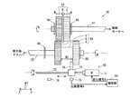
図1は、プリンタ100の全体の構成を示す図である。
Hereinafter, an embodiment of an image forming apparatus according to the present invention will be described using a tandem color digital printer (hereinafter simply referred to as “printer”) as an example.
<
[1] Overall Configuration of Printer FIG. 1 is a diagram illustrating the overall configuration of the
同図に示すように、プリンタ100は、周知の電子写真方式により画像を形成するものであり、画像プロセス部10と、中間転写部20と、給送部30と、定着部40と、制御部50を備え、ネットワーク(例えばLAN)に接続されて、外部の端末装置(不図示)からの印刷(プリント)ジョブの実行指示を受け付けると、その指示に基づいてイエロー(Y)、マゼンタ(M)、シアン(C)およびブラック(K)色からなるカラーの画像形成を実行する。
As shown in the figure, the
画像プロセス部10は、Y〜K色のそれぞれに対応する作像部10Y、10M、10C、10Kを備えている。
作像部10Yは、感光体ドラム11と、その周囲に配設された帯電器12、露光部13、現像部14、一次転写ローラ15、感光体ドラム11を清掃するためのクリーナ16などを備えており、感光体ドラム11上にY色のトナー像を作像する。この構成は、他の作像部10M、10C、10Kについて同様であり、同図では符号を省略している。各感光体ドラム11上にその対応する色のトナー像が作像される。
The
The
中間転写部20は、無端状の中間転写ベルト21と、中間転写ベルト21を張架する駆動ローラ22と従動ローラ23を備え、中間転写ベルト21は、駆動ローラ22の回転により同図の矢印方向に周回走行される。
給送部30は、給紙カセットから記録用のシートSを搬送路31に1枚ずつ繰り出す。
定着部40は、定着ローラと加圧ローラを備え、所定の定着温度でシートSを加熱、加圧してトナー像を定着させる。
The
The
The
制御部50は、外部の端末装置からの画像信号をY〜K色用のデジタル信号に変換し、作像部10Y〜10K毎に、その露光部13を駆動させるための駆動信号を生成して、その駆動信号により露光部13を駆動させる。これにより各露光部13からレーザビームが出射され、感光体ドラム11が露光走査される。
この露光走査を受ける前に作像部10Y〜10K毎に、その感光体ドラム11が帯電器12により一様に帯電されており、レーザビームの露光により感光体ドラム11上に静電潜像が形成され、その静電潜像が現像部14に設けられた現像ローラ19に担持されている現像剤により現像されて、感光体ドラム11上にトナー像が形成される。
The
Before the exposure scanning, the photosensitive drum 11 is uniformly charged by the
各感光体ドラム11上に形成されたトナー像は、一次転写ローラ15により中間転写ベルト21上に一次転写される。この際、各色の作像動作は、そのトナー像が中間転写ベルト21上の同じ位置に重ね合わせて転写されるようにタイミングをずらして実行される。
上記の作像動作のタイミングに合わせて、給送部30からは、タイミングローラ対34を介してシートSが給送されて来ており、そのシートSは、周回走行する中間転写ベルト21と二次転写ローラ35の間に挟まれて搬送され、中間転写ベルト21上の各色トナー像が二次転写ローラ35によりシートS上に二次転写される。
The toner image formed on each photosensitive drum 11 is primarily transferred onto the
The sheet S is fed from the
二次転写が終了したシートSは、定着部40に搬送され、ここでトナー像が加熱、加圧されてシートSに定着された後、排出ローラ対38を介して排出され、収容トレイ39に収容される。
作像部10Y〜10Kの感光体ドラム11や現像ローラ19、中間転写ベルト21を張架する駆動ローラ22などの各回転体は、駆動モータ32の回転駆動力が駆動ギアと従動ギアを含む駆動伝達機構を介して付与されることにより回転駆動される。
After the secondary transfer, the sheet S is conveyed to the fixing
Each rotating body such as the photosensitive drum 11 of the
〔2〕駆動伝達機構について
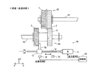
図2は、駆動伝達機構の一部を示す図であり、駆動モータ32からの回転駆動力が感光体ドラム11に至るまでの間の一部経路を示している。
同図に示すように、駆動伝達機構60は、駆動モータ32に連結される駆動軸61と、駆動軸61に支持される駆動ギア62と、駆動軸61と平行であり、感光体ドラム11に連結される従動軸63と、従動軸63に支持され、駆動ギア62と噛合する従動ギア64と、ギア変位機構65を備え、駆動モータ32の回転駆動力を駆動軸61、駆動ギア62、従動ギア64、従動軸63を介して感光体ドラム11に伝達する。
[2] Drive Transmission Mechanism FIG. 2 is a view showing a part of the drive transmission mechanism, and shows a partial path until the rotational driving force from the
As shown in the figure, the
なお、同図では歯車伝達機構における伝達経路の一部を示し、駆動軸61に駆動ギア62だけが取り付けられていることを示しているが、本実施の形態では別の駆動ギア(不図示)も取着されており、その別の駆動ギアから従動ギア(不図示)を介して感光体ドラム11以外の回転体に駆動力が伝達される構成になっている。なお、別の駆動ギアが取着されていない構成であっても構わない。以下、駆動軸61に平行な方向(従動軸63に平行な方向)を軸方向またはX方向、X´方向という場合がある。
In the figure, a part of the transmission path in the gear transmission mechanism is shown and only the
〔3〕駆動ギア62について
駆動ギア62は、樹脂製であり、軸方向に並設されるギア1と、ギア2と、これらを仕切る仕切り部8とが一体成形により形成されたものである。ここで、ギア1の歯数Z1は、ギア2の歯数Z2とは異なり、ギア1のピッチ円直径d1とギア2のピッチ円直径d2とは同じになっている。ギア1とギア2の軸方向における幅Wは、同じである。仕切り部8は、ギア1(ギア2)の歯先円直径よりもやや大きな径を有する円板状になっている。本実施の形態では、例えば歯数Z1=56、Z2=42、ギア1のモジュールm1=0.6、ギア2のモジュールm2=0.8になっている。
[3]
駆動ギア62は、駆動軸61に軸方向に間隔をおいて取着された2つのストップリング68に軸方向両側から挟まれるようになっており、軸方向への自由な移動が制限される。なお、ストップリング68は、ここでは、駆動軸61に設けられた溝(不図示)に嵌め込まれることにより、駆動軸61に取着される構成になっている。以下、ストップリングを取り付けるという場合は、これと同じ意味で用いられる。
The
〔4〕従動ギア64について
従動ギア64は、樹脂製であり、軸方向に並設されるギア3と、ギア4と、これらを連結する連結部9とが一体成形により形成されたものである。ここで、ギア3の歯数Z3は、ギア1の歯数Z1と同じであり、ギア4の歯数Z4は、ギア2の歯数Z2と同じであり、ギア3のピッチ円直径d3とギア4のピッチ円直径d4とは同じになっている。
[4] About the driven
ギア3のピッチ円直径d3は、ギア1のピッチ円直径d1と同じであり、従って、ピッチ円直径d1=d2=d3=d4の関係を有している。また、ギア3とギア4の幅はWであり、ギア1とギア2の幅Wと同じである。さらに、連結部9の軸方向長さ(ギア3とギア4の軸方向間隔)W1は、駆動ギア62のギア2の幅Wと仕切り部8の幅を加算した値よりも大きく、ここでは(2×W)の大きさになっている。
The pitch circle diameter d3 of the
連結部9は、断面が円形であり、その径がピッチ円直径d3の約半分程度の大きさであり、仕切り部8の外周面に接触することがないように縮径されている。
本実施の形態では、例えば歯数Z3=56、Z4=42、ギア3のモジュールm3=0.6、ギア4のモジュールm4=0.8になっている。
従動ギア64は、その軸方向における幅の約1.5倍程度の大きさに相当する間隔をおいて従動軸63に取着された2つのストップリング69に軸方向両側から挟まれるようになっており、一方のストップリング69と他方のストップリング69の間を軸方向に沿って摺動自在に支持されている。
The connecting
In the present embodiment, for example, the number of teeth Z3 = 56, Z4 = 42, the
The driven
〔5〕噛合するギアの組み合わせについて
このように駆動ギア62を軸方向への移動を制限しつつ、従動ギア64を軸方向への移動を自在に支持する構成をとることにより、駆動ギア62と従動ギア64における噛合するギアの組み合わせを切り替えることができる。
具体的には、駆動ギア62のギア1と従動ギア64のギア3が噛合するが、駆動ギア62のギア2と従動ギア64のギア4が噛合しない第1状態(図2に示す状態)と、駆動ギア62のギア2と従動ギア64のギア4が噛合するが、駆動ギア62のギア1と従動ギア64のギア3が噛合しない第2状態(後述の図4に示す状態)とを切り替えることが可能になる。
[5] Combination of meshing gears In this way, the
Specifically, the
第1状態と第2状態を切り替え可能に構成するのは、既存の装置の主要な部品を流用しつつ高速機を開発するに際して、駆動ギアと従動ギアの噛み合い周波数が装置固有の共振周波数に近づくことによる振動に起因する画質劣化を防止するためである。
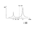
具体的に図3を用いて説明する。図3は、装置固有の共振周波数とギアの噛み合い周波数の大小関係の例を示すグラフである。同図では、装置本体の固有の共振周波数をf1、f2、既存の装置(低速機)において駆動軸の回転数を低速V1として、ギア1とギア3が噛合する第1状態にした場合の噛み合い周波数をf56L、ギア2とギア4が噛合する第2状態にした場合の噛み合い周波数をf42Lで示している。また、当該装置は、共振周波数f2の方がf1よりも振幅が大きくなる装置の例になっている。
The first state and the second state are configured to be switchable when the high-speed machine is developed while diverting the main parts of the existing device, the meshing frequency of the drive gear and the driven gear approaches the resonance frequency unique to the device. This is to prevent image quality deterioration due to vibration caused by the above.
This will be specifically described with reference to FIG. FIG. 3 is a graph showing an example of the magnitude relationship between the resonance frequency unique to the device and the meshing frequency of the gear. In the figure, meshing is performed when the first resonance state where the
同図に示すように、噛み合い周波数f42Lとf56Lの両方が共振周波数f1よりも大きく、共振周波数f2よりも小さい範囲内に入っているが、噛み合い周波数f42Lが共振周波数f1に接近しているのに対し、噛み合い周波数f56Lは、共振周波数f1、f2の両方から離れていることが判る。
噛み合い周波数が共振周波数に近づくと、それだけ共振による振動の影響を受け易く、画質劣化に繋がり易いので、既存の装置(低速機)では、噛み合い周波数がf56Lになる第1状態(図2)が選択される。
As shown in the figure, both the mesh frequencies f42L and f56L are larger than the resonance frequency f1 and smaller than the resonance frequency f2, but the mesh frequency f42L is close to the resonance frequency f1. On the other hand, it can be seen that the meshing frequency f56L is away from both the resonance frequencies f1 and f2.
When the meshing frequency approaches the resonance frequency, it is easily affected by vibration due to resonance, and the image quality is likely to deteriorate. Therefore, in the existing device (low speed machine), the first state (FIG. 2) in which the meshing frequency is f56L is selected. Is done.
この既存の装置を高速化するに当たり、ギア伝達機構を含む主要部品をそのまま流用して、駆動モータの回転数をV1からV2(>V1)に上げる構成をとると、低速時における噛み合い周波数f42L、56Lが駆動モータの回転数が上がった分、周波数が高くなる方向にシフトし、同図の破線で示す噛み合い周波数f42H、f56Hに変わる。
このとき、噛み合い周波数f56Hは、共振周波数f2にかなり接近するが、噛み合い周波数f42Hは、噛み合い周波数f56Hよりも共振周波数f2から離れており、かつ共振周波数f1からの離れるようになる。
In order to increase the speed of this existing apparatus, if the main component including the gear transmission mechanism is used as it is and the rotational speed of the drive motor is increased from V1 to V2 (> V1), the meshing frequency f42L at low speed is obtained. 56L shifts in the direction in which the frequency increases as the rotational speed of the drive motor increases, and changes to meshing frequencies f42H and f56H indicated by broken lines in FIG.
At this time, the meshing frequency f56H is considerably close to the resonance frequency f2, but the meshing frequency f42H is further away from the resonance frequency f2 than the meshing frequency f56H, and away from the resonance frequency f1.
従って、高速化した後の装置については、噛み合い周波数がf42Hになる第2状態に切り替えると、第1状態のままにするよりも共振による振動の影響を受け難くなり、画質劣化を抑制することが可能になる。
図4は、駆動ギア62と従動ギア64のうち、噛合するギアの組み合わせを第1状態から第2状態に切り替えた後の様子を示す図である。
Therefore, when the speed-up device is switched to the second state where the meshing frequency is f42H, it is less susceptible to vibration due to resonance than in the first state, and image quality deterioration is suppressed. It becomes possible.
FIG. 4 is a diagram showing a state after the combination of meshing gears of the
同図に示すように、駆動ギア62のギア2と従動ギア64のギア4が噛合して、駆動ギア62のギア1と従動ギア64のギア3が噛合しない第2状態になっており、歯数Zが共に42であるギア2とギア4が噛合している。従って、高速化により駆動モータの回転速度がV1からV2に切り替わった場合に、ギアの噛み合い周波数は、図3に示すf42Hになり、装置の共振周波数から離すことができることになる。
As shown in the figure, the
〔6〕ギア変位機構65について
図2に戻り、ギア変位機構65は、ネジ送り機構からなり、従動ギア64を軸方向に移動(シフト)させて、噛合するギアの組み合わせを切り替えるものであり、変位モータ71と、変位モータ71の回転軸に連結される送りネジ72と、送りネジ72に螺合するナット部73と、ナット部73に設けられ、従動ギア64に当接するアーム74と、アーム74の軸方向における位置を検出するためのセンサー75、76を備える。
[6]
変位モータ71は、制御部50からの変位信号により回転駆動し、送りネジ72は、軸方向に平行に配されており、変位モータ71の回転駆動により回転する。送りネジ72が回転すると、その回転方向と回転量に応じた分、ナット部73が軸方向に沿って直進移動する。ナット部73に一体的に設けられるアーム74は、軸方向に、従動ギア64のギア3とギア4の間に位置しており、ナット部73の軸方向の移動に伴って一緒に移動する。
The
アーム74が矢印X方向に移動すると、アーム74の先端部がギア4の内側の側面に当接した状態で従動ギア64をX方向に移動させる。その逆の矢印X´方向にアーム74が移動すると、アーム74の先端部がギア3の内側の側面に当接した状態で従動ギア64をX´方向に移動させる。
〔7〕制御部50の制御について
制御部50は、噛み合うギアの組み合わせの状態を第1状態にする場合には、図2に示すように変位モータ71に、従動ギア64をX方向に移動させるための変位信号Aを送り、変位モータ71を回転させる。これにより、ナット部73がX方向に移動して、この移動に伴って従動ギア64がX方向に移動される。ナット部73がセンサー75に対向する位置まで移動すると、その対向位置においてセンサー75により検出され、センサー75から位置信号Aが制御部50に送られる。
When the
[7] Control of the
制御部50は、センサー75からの位置信号Aを受信すると、変位信号Aの送信を停止して、変位モータ71を停止させる。
一方、噛み合うギアの組み合わせの状態を第1状態から第2状態に切り替える場合には、図4に示すように変位モータ71に、従動ギア64をX´方向に移動させるための変位信号Bを送り、変位モータ71を回転させる。これにより、ナット部73がX´方向に移動して、この移動に伴って従動ギア64がX´方向に移動される。
When receiving the position signal A from the
On the other hand, when the state of the meshing gear combination is switched from the first state to the second state, a displacement signal B for moving the driven
ナット部73がセンサー76に対向する位置まで移動すると、その対向位置においてセンサー76により検出され、センサー76から位置信号Bが制御部50に送られる。制御部50は、センサー76からの位置信号Bを受信すると、変位信号Bの送信を停止して、変位モータ71を停止させる。
なお、第1状態でも第2状態でも従動ギア64は、従動軸63に取着されているストップリング69とアーム74に挟まれることにより軸方向への自由な移動が制限される(噛合されているギア同士の噛合が解除されることがない)ようになっている。このような移動の制限を課させられるように、2つのストップリング69と69間における軸方向の間隔が設定されている。
When the
In both the first state and the second state, the driven
制御部50は、第1状態と第2状態の切り替えを操作者の指示により実行する。例えば、操作パネル(不図示)などの入力手段を介して切り替えの指示を受け付けると、その指示に対応する変位信号を変位モータ71に出力することにより切り替えを実行する。
例えば、プリンタ100を高速化する場合に、操作者が第1状態から第2状態への切り替えを入力手段から指示すると、制御部50がその指示を受け付けて、変位モータ71に変位信号Bを送信することにより、従動ギア64がX´方向に移動して(軸方向への移動を伴う動作が行われて)、ギア2とギア4が噛合し、ギア1とギア3が噛合しない第2状態に切り替わる。
The
For example, when the speed of the
また、操作者の指示に限られず、例えば制御部50内のCPUやROM(不図示)が低速用のものから高速化用のプログラムが入ったものに取り替えられた場合や、制御部50内のCPUに高速化用のファームウエアが新たにインストールされた場合などに、装置の起動時にそのプログラムやファームウエアを読み出す際に高速化対応を示すフラグなどを読み出することにより高速化対応にアップする旨を判断して、ギア噛合の組み合わせを第1状態から第2状態に切り替えるとしても良い。
Further, not limited to the instructions of the operator, for example, when the CPU or ROM (not shown) in the
なお、装置の高速化を行うには、実際には噛み合うギアの組み合わせを切り替える処理を行えば良いだけではなく、これ以外に、例えば駆動モータ32の回転を低速から高速駆動に切り替えるなどの他の処理も必要になるが、高速化を行うのに必要な処理自体は公知であるので、ここでは説明を省略する。
以上、説明したように本実施の形態では、ギア1とギア2からなる駆動ギア62と、ギア3とギア4からなる従動ギア64における噛合するギアの組み合わせを第1状態と第2状態に切り替え可能に構成しているので、既存の低速機を高速化するのに際し、第1状態のままであればギアの噛み合い周波数が装置固有の共振周波数に接近するような場合には、第2状態に切り替えることにより装置固有の共振周波数から遠ざけることができ、従来のように剛性部材や制振部材などの他の部材を用いなくても良くなって、部品管理上におけるコストと手間を不要としつつ、共振による振動に起因する画質劣化を防止して、一定以上の画質を維持することができる。
In addition, in order to increase the speed of the apparatus, it is not only necessary to actually switch the combination of gears engaged with each other. In addition to this, for example, the rotation of the
As described above, in the present embodiment, the combination of the meshing gear in the
また、第1状態でも第2状態でもギア比が1対1で同じになっているので、駆動軸61と従動軸63の回転速度が同じになる。駆動軸61には、感光体ドラム11とは別に、ギアの組み合わせを変更できない回転体(搬送ローラなど)も駆動ギア、従動ギアを介して連結されており、これら回転体は、駆動軸61の回転速度が低速から高速に切り替わった場合に、その速度差の分、速度が上がることになるが、感光体ドラム11も、これら回転体と同じ速度差の分だけ速度が上がることになる。
In addition, since the gear ratio is the same 1: 1 in both the first state and the second state, the rotational speeds of the
従って、感光体ドラム11だけギア組み合わせを切り替えることにより、高速時に他の回転体と速度差が生じるといったことを防止することができる。
さらに、第1状態(低速時)において噛み合うギア1とギア3のモジュールが共に0.6で、第2状態(高速時)において噛み合うギア2とギア4のモジュールが共に0.8になっており、高速時の方が低速時よりもモジュールの値が大きくなるようにしている。
Therefore, by switching the gear combination only for the photosensitive drum 11, it is possible to prevent a speed difference from another rotating body at a high speed.
Furthermore, the
一般に、モジュールの値が大きいとギアの歯元の厚みが厚くなって強度が増し、高速時の方が低速時よりもギア回転時にギアの歯にかかる負荷が大きくなることから、高速時に噛み合うギアであるギア2とギア4のモジュールを大きくとって強度を増すことにより、駆動力のギア伝達をより長期に亘って良好に行うことができる。
そして、歯数Zを低速側(ギア1とギア3)のモジュール(0.6)と高速側(ギア2とギア4)のモジュール(0.8)の倍数、ここでは70をとり、低速側では高速側のモジュール0.8に70を乗算した値の56歯、高速側では低速側のモジュール0.6に70を乗算した値の42歯としており、低速側と高速側のピッチ円直径d1〜d4が同じになるように設定することにより、低速から高速への切り替えに際し、駆動軸61と従動軸63の軸間距離を変える必要も生じない。
In general, the larger the module value, the thicker the gear teeth and the greater the strength. The higher the speed, the greater the load on the gear teeth when the gear rotates than the low speed. By increasing the size of the
The number of teeth Z is a multiple of the module (0.6) on the low speed side (
なお、上記では低速から高速に切り替える場合の例を説明したが、例えば高速から低速機に変更する場合でも同様に、噛合するギアの組み合わせを第1状態から第2状態または第2状態から第1状態に切り替えることにより、プリント速度を変更するに際し、ギア噛み合い周波数を共振周波数から遠ざけることができるという効果を得られる。
なお、上記の図3では、装置本体の共振周波数が複数、ここでは2つのf1、f2を有する旨を説明したが、例えば1つの共振周波数f1を有する構成でもギアの噛み合いの組みを切り替えることにより上記と同様の効果を得られる。
In addition, although the example in the case of switching from a low speed to a high speed has been described above, for example, when changing from a high speed to a low speed machine, the gear combination to be engaged is changed from the first state to the second state or from the second state to the first state. By switching to the state, it is possible to obtain an effect that the gear meshing frequency can be kept away from the resonance frequency when the printing speed is changed.
In FIG. 3 described above, it has been described that the apparatus main body has a plurality of resonance frequencies, here two f1 and f2. However, for example, even in a configuration having one resonance frequency f1, the gear meshing combination is switched. The same effect as above can be obtained.
具体的には、ギア噛み合い周波数をより大きくした方がギアの噛み合い振動により画像に現れるピッチムラが小さくなるような装置構成の場合には、低速時において歯数の多い方のギア2と4の組み合わせが選択され、ギア2と4を噛合させたときに共振周波数f1と離れるように歯数が設定される。
高速化に伴い、ギア2と4を噛合させたままにすればギアの噛み合い周波数が共振周波数f1に接近する場合には、ギア2と4に代えて、ギア1と3を噛合させることにより、ギア2と4の組みよりもギアの噛み合い周波数を共振周波数f1から遠ざけることができる。なお、ギア1と3は、ギア2と4よりも歯数が少ないが、高速化により駆動軸61の回転数が上がっているため、その回転数の上昇分、ギア1と3の噛み合い周波数も低速時よりも上がっていることになり、ギア1と3を噛合させる場合でも低速時に比べると、ピッチムラの発生を抑制することができる。
Specifically, in the case of a device configuration in which the higher the gear meshing frequency is, the smaller the pitch unevenness that appears in the image due to gear meshing vibration is, the combination of
As the speed increases, if the
<実施の形態2>
上記実施の形態では、従動ギア64をネジ送り機構であるギア変位機構65を用いて自動的に軸方向における位置を変位させるとしたが、本実施の形態では、このようなギア変位機構が採用されておらず、この点が実施の形態1と異なっている。以下、説明の重複を避けるため、第1の実施の形態と同じ内容についてはその説明を省略し、同じ構成要素については、同符号を付すものとする。
<
In the above embodiment, the driven
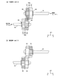
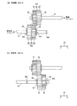
図5は、本実施の形態における駆動ギア80aと従動ギア80bの構成を示す図であり、(a)は低速時を、(b)は高速時をそれぞれ示している。
両図に示すように、駆動ギア80aは、軸方向に並設されるギア81と、ギア82と、これらを仕切る仕切り部88とが一体成形により形成されたものであり、実施の形態1における駆動ギア62と実質、同じものである。
FIGS. 5A and 5B are diagrams showing the configuration of the
As shown in both figures, the
従動ギア80bは、軸方向に並設されるギア83と、ギア84と、これらを仕切る仕切り部89とが一体成形により形成されたものであり、駆動ギア80aと同じ部品であり、駆動ギア80aに対して軸方向に左右が反転したような状態で取着されている。
駆動ギア80aは、駆動軸61に軸方向に間隔をおいて取着された2つのストップリング68に軸方向両側から挟まれるようになっており、同様に従動ギア80bは、従動軸63に軸方向に間隔をおいて取着された2つのストップリング69に軸方向両側から挟まれるようになっており、それぞれが軸方向への自由な移動が制限される。
The driven
The
なお、ギア81〜ギア84のそれぞれの歯数Z、ピッチ円直径d、モジュールmは、基本的に実施の形態1のものと同じである。
低速時では図5(a)に示すように、ギア81とギア83が噛合し、ギア82とギア84が噛合しない第1状態になる。第1状態から第2状態への切り替えは、本実施の形態では操作者の手動により実行される。
Note that the number of teeth Z, the pitch circle diameter d, and the module m of each of the
At low speed, as shown in FIG. 5A, the
すなわち、図5(a)に示す第1状態において、操作者がストップリング68、69を駆動軸61、従動軸63から取り外し、駆動ギア80aと従動ギア80bの一方と他方を順次、軸方向にずらすことにより、駆動ギア80aと従動ギア80bを駆動軸61と従動軸63から引き抜く。そして、駆動ギア80aと従動ギア80bのそれぞれを、引き抜いたときの姿勢に対して軸方向に反転させた姿勢に代えて、再度、駆動軸61と従動軸63に挿入した後、ストップリング68、69を駆動軸61、従動軸63に取り付ける操作を行うことにより、第2状態に切り替えることができる。
That is, in the first state shown in FIG. 5A, the operator removes the stop rings 68 and 69 from the
図5(b)は、第2状態に切り替えた後の駆動ギア80aと従動ギア80bの姿勢を示しており、ギア82とギア84が噛合し、ギア81とギア83が噛合しない状態になっていることが判る。第1状態と第2状態において噛合すべきギアが噛合されるように、ストップリング68、69による駆動ギア80aと従動ギア80bの軸方向における位置が設定される。
FIG. 5B shows the postures of the
このように駆動ギア80aと従動ギア80bを軸方向への移動を伴う操作を行うことにより、噛合するギアの組み合わせを第1の状態と第2の状態を切り替えることができると共に、駆動ギア80aと従動ギア80bを同じ部品として製造することにより、部品を共用化して同じ部品(部材)を兼用すると共に、モータや送りネジ機構等が不要になって、歯車伝達機構の簡素化と共に低コスト化を図ることができる。
Thus, by performing an operation involving movement of the
また、駆動ギア80aと従動ギア80bを駆動軸61と従動軸63に対して挿抜可能にして、第1と第2の状態を切り替える際には、軸から取り外す前の姿勢に対して駆動ギア80aと従動ギア80bを、軸方向に左右反転した姿勢で軸着可能にすることにより、図5に示すように、低速時でも高速時でも駆動ギア80aと従動ギア80bの軸に対する位置が変わらず、ギア組み合わせの切り替えのために軸長を延長することが不要になる。
In addition, when the
<実施の形態3>
上記実施の形態2では、駆動ギア80aと従動ギア80bを駆動軸61と従動軸63から取り外すことにより第1状態と第2状態の切り替えを行うとしたが、本実施の形態では、駆動ギア80aだけを取り外し従動ギア80bを取り外さずに軸方向にスライドさせることにより切り替えを行うとしており、この点が実施の形態2と異なっている。
<
In the second embodiment, the
図6は、本実施の形態における駆動ギア80aと従動ギア80bの駆動軸61と従動軸63への取り付け構成を示す図であり、(a)は低速時を、(b)は高速時をそれぞれ示している。
両図に示すように、駆動ギア80aと従動ギア80bは、実施の形態2における駆動ギアと従動ギアと同じものであり、駆動軸61も実施の形態2における駆動軸と同じものである。従動軸63には、ストップリング69を嵌め込むための3つの溝96a、96b、96cが軸方向に間隔をおいて設けられている。なお、図6(a)では、溝96a、96cにストップリング69が嵌め込まれているので、溝96a、96cが見えず、溝96bだけが示され、図6(b)では、溝96b、96cにストップリング69が嵌め込まれているので、溝96b、96cが見えず、溝96aだけが示されている。
FIGS. 6A and 6B are diagrams showing a configuration in which the
As shown in both figures, the
図6(a)に示すように、低速時では、溝96aと96cに嵌め込まれている2つのストップリング69に従動ギア80bが挟まれて軸方向への自由な移動が制限されるようになっており、ギア81とギア83が噛合し、ギア82とギア84が噛合しない第1状態になっている。
この第1状態において、操作者がストップリング68、69を駆動軸61、従動軸63から取り外し、駆動ギア80aと従動ギア80bをX´方向にずらすように移動させて、駆動ギア80aを駆動軸61から引き抜く。そして、1つのストップリング69を従動軸63の溝96bに嵌め込んで取着した後、従動ギア80bを手動でX方向に移動させて、溝96bに嵌め込まれたストップリング69に当たる位置で停止させる。
As shown in FIG. 6A, at the time of low speed, the
In this first state, the operator removes the stop rings 68 and 69 from the
そして、従動軸63の溝96cに残りのストップリング69を嵌め込んで取り着け、それから駆動ギア80aを駆動軸61から引き抜いたときと同じ姿勢のまま、再度、駆動軸61に挿入した後、2つのストップリング68を駆動軸61に取り着ける操作を行うことにより、第2状態に切り替えることができる。
図6(b)は、第2状態に切り替えた後の駆動ギア80aと従動ギア80bの姿勢を示しており、従動軸63の溝96b、96cに嵌め込まれた2つのストップリング69の間に従動ギア80bが挟まれるように配置され、ギア82とギア84が噛合し、ギア81とギア83が噛合しない状態になっていることが判る。
Then, the remaining
FIG. 6B shows the postures of the
第1状態と第2状態において噛合すべきギアが噛合されるように、ストップリング68、69による駆動ギア80aと従動ギア80bの軸方向における位置が設定される。
このように構成すれば、従動ギア80bを従動軸63から取り外さなくて済む分、操作者にとって第1状態と第2状態の切り替え操作を簡略化することが可能になる。
なお、上記では駆動ギア80aと従動ギア80bに、ギア81〜ギア84よりも大径の仕切り部88、89を設けているために、駆動ギア80aに対して従動ギア80bを軸方向に沿ってスライドさせようとすると歯先と仕切り部の周縁部とが当たってしまい、このため従動ギア80bをスライドさせることができないことから、駆動ギア80aを駆動軸61から取り外す必要が生じた。
The axial positions of the
With this configuration, the switching operation between the first state and the second state can be simplified for the operator because the driven
In the above description, since the
これに対して、例えば仕切り部88、89の径をギア81等と同じまで縮径する構成、または仕切り部88、89を設けない構成をとれば、駆動ギア80aに対して従動ギア80bを軸方向に従動軸63に沿ってスライド自在にすることができるので、駆動ギア80aを駆動軸61から取り外す必要がなくなり、より操作を簡略化することができる。
この構成をとれば、駆動ギア80aと従動ギア80bのうち、一方のギアを軸に固定し、他方のギアを軸に移動自在に支持して、移動自在に支持されている方のギアを軸方向に移動させることにより、噛合するギアの組み合わせを切り替える構成をとることもできる。また、図6の構成において実施の形態1のようにネジ送り機構を用いて従動ギア80bを軸方向にスライドさせることにより噛合するギアの組み合わせを第1状態と第2状態を切り替えることもできる。
On the other hand, for example, if the configuration in which the diameter of the
With this configuration, one of the
<変形例>
以上、本発明を実施の形態に基づいて説明してきたが、本発明は、上述の実施の形態に限定されないのは勿論であり、以下のような変形例が考えられる。
(1)上記実施の形態1では、駆動ギア62のギア1のピッチ円直径d1とギア2のピッチ円直径d2、従動ギア64のギア3のピッチ円直径d3とギア4のピッチ円直径d4が、d1=d2=d3=d4の関係を満たし、ギア1の歯数Z1とギア3の歯数Z3が、Z1=Z3(=56歯)、ギア2の歯数Z2とギア4の歯数Z4が、Z2=Z4(=42歯)の関係を満たし、ギア1のモジュールm1、ギア3のモジュールm3が、m1=m3(=0.6)、ギア2のモジュールm2、ギア4のモジュールm4が、m2=m4(=0.8)の関係を満たすとしたが、これらに限られることはない。
<Modification>
As described above, the present invention has been described based on the embodiment. However, the present invention is not limited to the above-described embodiment, and the following modifications may be considered.
(1) In the first embodiment, the pitch circle diameter d1 of the
ギア1とギア3が噛合し、ギア2とギア4が噛合しない第1状態において、駆動軸61の回転速度がVのときにおけるギア1とギア3の噛み合い周波数H1と、ギア2とギア4が噛合し、ギア1とギア3が噛合しない第2状態において、駆動軸61の回転速度が上記と同じ速度Vのときにおけるギア2とギア4の噛み合い周波数H2が異なるようにすれば、第1状態と第2状態のうち、低速時に一方の状態であり、高速に切り替える際にその一方の状態のままでは装置の共振周波数に近づく場合には、噛合するギアの組み合わせを他方の状態に切り替えることにより、装置の共振周波数から遠ざけることが可能になる。
In the first state where the
具体的な構成としては、歯数Z1とZ2が異なることを条件に、例えばピッチ円直径をd1=d2でありd3=d4かつd1<d3とする構成や、d1=d2でありd3=d4かつd1>d3とする構成をとることができる。この場合、噛合する同士のギアのモジュールを同じ値にすると、m=d/Zの関係から、歯数Z1と歯数Z3が異なり、歯数Z2と歯数Z4が異なり、ギア比が1にならないことになる。 Specifically, on the condition that the number of teeth Z1 and Z2 are different, for example, the pitch circle diameter is d1 = d2, d3 = d4 and d1 <d3, or d1 = d2, d3 = d4 and A configuration of d1> d3 can be adopted. In this case, if the meshing gear modules have the same value, from the relationship of m = d / Z, the number of teeth Z1 and the number of teeth Z3 are different, the number of teeth Z2 and the number of teeth Z4 are different, and the gear ratio is 1. It will not be.
これとは別に、例えばd1=d4でありd2=d3かつd1<d2とする構成や、d1=d4でありd2=d3かつd1>d2とする構成をとることもできる。この場合、歯数Z1とZ4が同じであり、Z2とZ3を同じ構成とすることができる。
駆動ギア62と従動ギア64の少なくとも一方を、軸方向への移動を伴う動作により第1状態と第2状態を切り替え可能なように、ギア1〜ギア4のそれぞれのピッチ円直径d1〜d4と、ギア1とギア2の軸方向間隔と、ギア3とギア4の軸方向間隔が設定され、かつ、ギア1の歯数Z1がギア2の歯数Z2とは異なるようになっている。
Apart from this, for example, it is possible to adopt a configuration in which d1 = d4, d2 = d3 and d1 <d2, or a configuration in which d1 = d4, d2 = d3 and d1> d2. In this case, the number of teeth Z1 and Z4 are the same, and Z2 and Z3 can have the same configuration.
The pitch circle diameters d1 to d4 of each of the
具体的には、歯数Z1とZ2が異なり、かつピッチ円直径d1とd3を加算した値αと、ピッチ円直径d2とd4を加算した値βとが同じであれば、駆動軸61と従動軸63の軸間距離を変えることなく、噛合するギアの組み合わせを第1状態と第2状態に切り替えることができる。なお、噛合するギア同士であるギア1とギア3の組、ギア2とギア4の組のそれぞれについて、ギアによる駆動力の伝達に支障のない範囲で装置構成に応じて、ピッチ円直径d、歯数Z、モジュールmの適した値が決められる。従って、仮に軸間距離が可変可能な構成の場合には、上記値αとβとが一致しない構成もあり得る。これらのことは、実施の形態2、3について同様である。
Specifically, if the number of teeth Z1 and Z2 is different and the value α obtained by adding the pitch circle diameters d1 and d3 is the same as the value β obtained by adding the pitch circle diameters d2 and d4, the
また、モジュールは、高速側の方が低速側よりも大きくなる関係に設定されることが望ましいが、逆の関係になっても良い。
(2)上記実施の形態では、駆動モータ32の回転駆動力を、歯車を含む駆動伝達機構60を介して、画像形成に関与する被駆動回転体に伝える構成において、被駆動回転体を感光体ドラム11に適用した例を説明したが、これに限られることはない。被駆動回転体としては、共振に起因する振動により画質に影響を及ぼし易い回転体、例えば現像剤を担持して感光体ドラム11上の静電潜像をトナーで現像する現像ローラ19や、中間転写ベルト21を周回駆動させるための駆動ローラ22などに適用することができる。
In addition, it is desirable that the modules be set to have a relationship such that the high-speed side is larger than the low-speed side, but the reverse relationship may be used.
(2) In the above embodiment, in the configuration in which the rotational driving force of the driving
また、中間転写ベルト21を用いる構成ではなく、感光体ドラムに転写ローラを接触させて、両者間を記録シートが通過する際に、感光体ドラム上に形成されたトナー像を記録シートに転写する構成において、転写ローラが回転駆動される場合に当該転写ローラを被駆動回転体として適用することもできる。画像形成に関与する感光体ドラム、現像ローラ、駆動ローラ、転写ローラなどの複数の被駆動回転体がある場合に、これら複数の被駆動回転体の少なくとも1つに対して、上記の駆動ギアと従動ギアを適用することができる。
Further, instead of using the
(3)上記実施の形態1では、従動ギア64を軸方向にスライド可変可能な変位機構として、ネジ送り機構を用いた例を説明したが、これに限られない。移動可能に支持される従動ギア64に軸方向の力を与えて従動ギア64を軸方向に移動させるアクチュエータを有する変位機構であれば良い。例えば、ソレノイドのプランジャーや直動モータの軸を進退させることにより従動ギア64を変位させる機構などを用いることもできる。
(3) In the first embodiment, the example in which the screw feed mechanism is used as the displacement mechanism that can slide the driven
また、上記実施の形態1では、駆動ギア62を駆動軸61に軸方向に移動しないように取着(固定)し、従動ギア64を従動軸63に対して軸方向に沿って摺動自在に支持するとしたが、これに限られない。噛合するギアの組み合わせを第1状態と第2状態に切り替えることができるように、駆動ギア62と従動ギア64を軸方向に沿って相対移動可能(少なくとも一方のギアを移動可能)に構成すれば良い。例えば、上記の固定側と移動側の関係を逆にする構成、すなわち駆動ギア62を移動側、従動ギア64を固定側にする構成をとるとしても良い。
In the first embodiment, the
(4)上記実施の形態では、本発明に係る画像形成装置をタンデム型カラーデジタルプリンタに適用した場合の例を説明したが、これに限られない。カラーやモノクロの画像形成に関わらず、モータなどの駆動源からの回転駆動力を駆動ギアからこれに噛合する従動ギアを介して、感光体ドラムや中間転写ベルトなどの像担持回転体、現像ローラなどの現像剤担持回転体などの被駆動回転体に伝えて、被駆動回転体を回転駆動させる構成の画像形成装置であれば、例えば複写機、FAX、MFP(Multiple Function Peripheral)等に適用できる。 (4) In the above embodiment, an example in which the image forming apparatus according to the present invention is applied to a tandem color digital printer has been described, but the present invention is not limited to this. Regardless of color or monochrome image formation, an image bearing rotating body such as a photosensitive drum or an intermediate transfer belt, a developing roller via a driven gear that meshes with a rotational driving force from a driving source such as a motor. Any image forming apparatus configured to transmit to a driven rotating body such as a developer-carrying rotating body and rotate the driven rotating body can be applied to, for example, a copying machine, FAX, MFP (Multiple Function Peripheral), and the like. .
上記では、駆動ギア62と従動ギア64が樹脂成形によるものとしたが、これに限られず、例えば金属製のものであっても良い。なお、駆動ギア62、従動ギア64の歯数Z、モジュールmの値が上記の数値に限られないことはいうまでもなく、また、ギア1〜4の幅Wを同じとしたが、これに限られず、異なるものであっても良い。さらに、駆動軸や従動軸にストップリングを嵌めることにより駆動ギア62を軸方向への移動を規制(駆動軸61に固定)するとしたが、固定する方法がストップリングを用いる構成に限られないことはいうまでもなく、他の部材や方法を用いるとしても構わない。
In the above description, the
また、静電潜像が形成される像担持回転体の例として感光体ドラムを用いる構成を説明したが、ドラム状に限られず、例えばベルト状のものを用いるとしても良い。また、現像剤を担持する現像剤担持回転体の例として、現像ローラを用いる構成を説明したが、現像剤担持回転体は、像担持回転体上に作像された静電潜像を現像剤で現像して像担持回転体上に現像剤像を形成するものであれば良く、例えばベルト状のものでも良い。 Further, the configuration using the photosensitive drum as an example of the image bearing rotating body on which the electrostatic latent image is formed has been described. However, the configuration is not limited to the drum shape, and for example, a belt shape may be used. Further, the configuration using the developing roller has been described as an example of the developer carrying rotator that carries the developer. However, the developer carrying rotator uses the electrostatic latent image formed on the image carrying rotator as the developer. In other words, a belt-like one may be used as long as it develops the toner image and forms a developer image on the image bearing rotating body.
さらに、中間転写ベルト21が駆動ローラ22と従動ローラ23により張架されるとしたが、これらを含む複数のローラにより張架される構成であっても良い。また、駆動源として駆動モータ32を用いるとしたが、回転駆動力を出力するものであれば、モータに限られることもない。
また、上記実施の形態及び上記変形例の内容をそれぞれ組み合わせるとしても良い。
Further, although the
The contents of the above embodiment and the above modification may be combined.
本発明は、駆動源からの回転駆動力を駆動ギアから従動ギアを介して、画像形成に関与する被駆動回転体に伝達する画像形成装置に広く適用することができる。 The present invention can be widely applied to an image forming apparatus that transmits a rotational driving force from a driving source from a driving gear to a driven rotating body involved in image formation via a driven gear.
1、2、3、4、81、82、83、84 ギア
11 感光体ドラム(像担持回転体)
19 現像ローラ(現像剤担持回転体)
21 中間転写ベルト
22 駆動ローラ
32 駆動モータ
50 制御部
61 駆動軸
62、80a 駆動ギア
63 従動軸
64、80b 従動ギア
65 ギア変位機構
100 プリンタ
1, 2, 3, 4, 81, 82, 83, 84 Gear 11 Photosensitive drum (image bearing rotating body)
19 Developing roller (developer carrying rotating body)
21
Claims (11)
前記駆動ギアは、
駆動軸の軸方向に並設された第1ギアと第2ギアが一体形成されてなり、
前記従動ギアは、
従動軸の軸方向に並設された第3ギアと第4ギアが一体形成されてなり、
前記駆動ギアと前記従動ギアの少なくとも一方を軸方向への移動を伴う動作を行うことにより、第1ギアと第3ギアが噛合して第2ギアと第4ギアが噛合しない第1状態と、第2ギアと第4ギアが噛合して第1ギアと第3ギアが噛合しない第2状態を切り替え可能なように、第1ギア、第2ギア、第3ギア、第4ギアのピッチ円直径が設定され、
駆動側である第1ギアの歯数Z1と第2ギアの歯数Z2とが異なっていることを特徴とする画像形成装置。 An image forming apparatus having a drive transmission mechanism for transmitting a rotational driving force from a driving source from a driving gear to a driven rotating body involved in image formation via a driven gear,
The drive gear is
A first gear and a second gear arranged in parallel in the axial direction of the drive shaft are integrally formed,
The driven gear is
A third gear and a fourth gear arranged in parallel in the axial direction of the driven shaft are integrally formed,
A first state in which the first gear and the third gear mesh with each other and the second gear and the fourth gear do not mesh with each other by performing an operation involving movement in the axial direction of at least one of the drive gear and the driven gear; Pitch circle diameters of the first gear, the second gear, the third gear, and the fourth gear so that the second state in which the second gear and the fourth gear mesh and the first gear and the third gear do not mesh can be switched. Is set,
An image forming apparatus, wherein the number of teeth Z1 of the first gear on the driving side and the number of teeth Z2 of the second gear are different.
第1ギアが第2ギアに対して軸方向に一方の側に位置し、第2ギアが第1ギアに対して他方の側に位置するように前記駆動軸に支持され、
前記従動ギアは、
第4ギアが第3ギアに対して軸方向に前記一方の側と同じ側に位置し、第3ギアが第4ギアに対して前記他方の側と同じ側に位置するように前記従動軸に支持され、
前記駆動ギアと従動ギアのうち、一方のギアが軸方向に固定され、他方のギアが軸方向に移動自在に支持され、
前記移動自在に支持される方のギアが前記軸方向に移動されることにより、第1ギアと第3ギアが噛合し、第2ギアと第4ギアが噛合しない第1状態と、第2ギアと第4ギアが噛合し、第3ギアと第4ギアが噛合しない第2状態とが切り替え可能になっていることを特徴とする請求項5に記載の画像形成装置。 The drive gear is
The first gear is supported on the drive shaft so as to be positioned on one side in the axial direction with respect to the second gear, and the second gear is positioned on the other side with respect to the first gear,
The driven gear is
The driven gear is positioned on the driven shaft such that the fourth gear is positioned on the same side as the one side in the axial direction with respect to the third gear, and the third gear is positioned on the same side as the other side with respect to the fourth gear. Supported,
Of the drive gear and the driven gear, one gear is fixed in the axial direction, and the other gear is supported movably in the axial direction,
A first state in which the first gear and the third gear mesh with each other, and the second gear and the fourth gear mesh with each other, and the second gear, when the movably supported gear is moved in the axial direction. 6. The image forming apparatus according to claim 5, wherein the second state where the third gear and the fourth gear mesh with each other and the third gear and the fourth gear mesh with each other can be switched.
駆動軸から取り外された駆動ギアが、取り外される前の姿勢に対して軸方向に反転した姿勢で駆動軸に軸着可能であり、
従動軸から取り外された従動ギアが、取り外される前の姿勢に対して軸方向に反転した姿勢で従動軸に軸着可能であることを特徴とする請求項3〜5のいずれか1項に記載の画像形成装置。 The drive gear and the driven gear can be inserted into and removed from the drive shaft and the driven shaft,
The drive gear removed from the drive shaft can be attached to the drive shaft in a posture reversed in the axial direction with respect to the posture before being removed,
6. The driven gear removed from the driven shaft can be attached to the driven shaft in a posture reversed in the axial direction with respect to the posture before being removed. 6. Image forming apparatus.
一方のギアが軸方向に沿って移動自在であり、他方のギアが軸方向に固定されており、
前記画像形成装置は、
前記移動自在に支持されている一方のギアに対して軸方向への力を与えて当該一方のギアを移動させるアクチュエータと、
前記アクチュエータを制御して、噛合するギアの組み合わせを第1状態から第2状態に遷移させる場合には、第2ギアと第4ギアが噛合する位置まで前記移動自在に支持されている一方のギアを移動させ、第2状態から第1状態に遷移させる場合には、第1ギアと第3ギアが噛合する位置まで前記一方のギアを移動させる制御手段と、
を備えることを特徴とする請求項1〜6、8のいずれか1項に記載の画像形成装置。 The drive gear and the driven gear are
One gear is movable along the axial direction, the other gear is fixed in the axial direction,
The image forming apparatus includes:
An actuator for moving the one gear by applying an axial force to the one gear supported movably;
One gear that is movably supported to a position where the second gear and the fourth gear mesh when the combination of gears to be meshed is changed from the first state to the second state by controlling the actuator. Control means for moving the one gear to a position where the first gear and the third gear mesh with each other,
The image forming apparatus according to claim 1, further comprising:
前記被駆動回転体は、前記像担持回転体および前記現像剤担持回転体の少なくとも一方であることを特徴とする請求項1〜9のいずれか1項に記載の画像形成装置。 The electrostatic latent image formed on the image carrying rotator is developed with a developer carried on the developer carrying rotator to form a developer image on the image carrying rotator,
The image forming apparatus according to claim 1, wherein the driven rotating body is at least one of the image bearing rotating body and the developer bearing rotating body.
前記被駆動回転体は、前記駆動ローラであることを特徴とする請求項1〜9のいずれか1項に記載の画像形成装置。 The developer image formed on the image bearing rotator is transferred onto a belt stretched by a plurality of rollers including a driving roller and a driven roller.
The image forming apparatus according to claim 1, wherein the driven rotating body is the driving roller.
Priority Applications (1)
| Application Number | Priority Date | Filing Date | Title |
|---|---|---|---|
| JP2010137645A JP2012003019A (en) | 2010-06-16 | 2010-06-16 | Image forming apparatus |
Applications Claiming Priority (1)
| Application Number | Priority Date | Filing Date | Title |
|---|---|---|---|
| JP2010137645A JP2012003019A (en) | 2010-06-16 | 2010-06-16 | Image forming apparatus |
Publications (1)
| Publication Number | Publication Date |
|---|---|
| JP2012003019A true JP2012003019A (en) | 2012-01-05 |
Family
ID=45535074
Family Applications (1)
| Application Number | Title | Priority Date | Filing Date |
|---|---|---|---|
| JP2010137645A Withdrawn JP2012003019A (en) | 2010-06-16 | 2010-06-16 | Image forming apparatus |
Country Status (1)
| Country | Link |
|---|---|
| JP (1) | JP2012003019A (en) |
Cited By (6)
| Publication number | Priority date | Publication date | Assignee | Title |
|---|---|---|---|---|
| JP2014170172A (en) * | 2013-03-05 | 2014-09-18 | Brother Ind Ltd | Image forming apparatus |
| JP2017058571A (en) * | 2015-09-18 | 2017-03-23 | コニカミノルタ株式会社 | Image forming apparatus |
| JP2017076102A (en) * | 2015-05-15 | 2017-04-20 | 株式会社リコー | Image forming apparatus |
| WO2018030600A1 (en) * | 2016-08-09 | 2018-02-15 | S-Printing Solution Co., Ltd | Development cartridge and electrophotographic image forming apparatus adopting the same |
| CN114311381A (en) * | 2021-12-31 | 2022-04-12 | 京东橡胶有限公司 | Speed ratio on-line switching type double-roller rubber open mill |
| CN118986361A (en) * | 2024-10-24 | 2024-11-22 | 安徽优医康医疗科技有限公司 | Electrode adjusting device |
-
2010
- 2010-06-16 JP JP2010137645A patent/JP2012003019A/en not_active Withdrawn
Cited By (7)
| Publication number | Priority date | Publication date | Assignee | Title |
|---|---|---|---|---|
| JP2014170172A (en) * | 2013-03-05 | 2014-09-18 | Brother Ind Ltd | Image forming apparatus |
| JP2017076102A (en) * | 2015-05-15 | 2017-04-20 | 株式会社リコー | Image forming apparatus |
| JP2017058571A (en) * | 2015-09-18 | 2017-03-23 | コニカミノルタ株式会社 | Image forming apparatus |
| WO2018030600A1 (en) * | 2016-08-09 | 2018-02-15 | S-Printing Solution Co., Ltd | Development cartridge and electrophotographic image forming apparatus adopting the same |
| CN114311381A (en) * | 2021-12-31 | 2022-04-12 | 京东橡胶有限公司 | Speed ratio on-line switching type double-roller rubber open mill |
| CN114311381B (en) * | 2021-12-31 | 2023-09-22 | 京东橡胶有限公司 | Speed ratio on-line switching type double-roller rubber open mill |
| CN118986361A (en) * | 2024-10-24 | 2024-11-22 | 安徽优医康医疗科技有限公司 | Electrode adjusting device |
Similar Documents
| Publication | Publication Date | Title |
|---|---|---|
| JP5022834B2 (en) | Image forming apparatus | |
| JP5532756B2 (en) | Image forming apparatus | |
| JP2012003019A (en) | Image forming apparatus | |
| JP6146603B2 (en) | GEAR TRANSMISSION DEVICE, PROCESS UNIT HAVING THE DEVICE, AND IMAGE FORMING DEVICE | |
| JP6160256B2 (en) | Image forming apparatus | |
| JP5212010B2 (en) | Planetary differential gear reducer, image forming device | |
| JP2008281933A (en) | Transfer device, image forming device | |
| JP2007322519A (en) | Image forming apparatus | |
| JP2005157169A (en) | Image forming apparatus and process unit | |
| JP7134669B2 (en) | One-way clutch, sheet conveying device, and image forming device | |
| JP2017211456A (en) | Drive power transmission mechanism and image formation apparatus with the same | |
| JP5919648B2 (en) | Sheet discharge driving device and image forming apparatus | |
| JP2009151182A (en) | Drive transmission device for image forming apparatus and image forming apparatus | |
| JP2010140060A (en) | Image forming apparatus | |
| JP2016099440A (en) | Image forming apparatus | |
| JP2004177508A (en) | Image carrier driving device and image forming device | |
| JP6697710B2 (en) | Speed switching device, drive device and image forming device | |
| JP2007047629A (en) | Image forming apparatus | |
| JP5074081B2 (en) | Gear reinforcement structure and image forming apparatus | |
| JP4964548B2 (en) | Driving device, cleaning device, and image forming device | |
| JP2009251349A (en) | Drive device and image forming apparatus | |
| JP2009271361A (en) | Belt drive device, transfer device, transfer fixing device, and image forming apparatus | |
| JP5882624B2 (en) | Belt unit and image forming apparatus | |
| JP4820150B2 (en) | Rotation speed detector | |
| US20090302531A1 (en) | Beltless tandem-type image forming apparatus |
Legal Events
| Date | Code | Title | Description |
|---|---|---|---|
| A711 | Notification of change in applicant |
Free format text: JAPANESE INTERMEDIATE CODE: A712 Effective date: 20130417 |
|
| A300 | Withdrawal of application because of no request for examination |
Free format text: JAPANESE INTERMEDIATE CODE: A300 Effective date: 20130903 |