JP2011530027A - Combined cycle energy generation system - Google Patents
Combined cycle energy generation system Download PDFInfo
- Publication number
- JP2011530027A JP2011530027A JP2011516930A JP2011516930A JP2011530027A JP 2011530027 A JP2011530027 A JP 2011530027A JP 2011516930 A JP2011516930 A JP 2011516930A JP 2011516930 A JP2011516930 A JP 2011516930A JP 2011530027 A JP2011530027 A JP 2011530027A
- Authority
- JP
- Japan
- Prior art keywords
- steam
- turbine
- energy generation
- combined cycle
- generation system
- Prior art date
- Legal status (The legal status is an assumption and is not a legal conclusion. Google has not performed a legal analysis and makes no representation as to the accuracy of the status listed.)
- Pending
Links
Images


Classifications
-
- F—MECHANICAL ENGINEERING; LIGHTING; HEATING; WEAPONS; BLASTING
- F02—COMBUSTION ENGINES; HOT-GAS OR COMBUSTION-PRODUCT ENGINE PLANTS
- F02C—GAS-TURBINE PLANTS; AIR INTAKES FOR JET-PROPULSION PLANTS; CONTROLLING FUEL SUPPLY IN AIR-BREATHING JET-PROPULSION PLANTS
- F02C3/00—Gas-turbine plants characterised by the use of combustion products as the working fluid
- F02C3/20—Gas-turbine plants characterised by the use of combustion products as the working fluid using a special fuel, oxidant, or dilution fluid to generate the combustion products
- F02C3/30—Adding water, steam or other fluids for influencing combustion, e.g. to obtain cleaner exhaust gases
- F02C3/305—Increasing the power, speed, torque or efficiency of a gas turbine or the thrust of a turbojet engine by injecting or adding water, steam or other fluids
-
- F—MECHANICAL ENGINEERING; LIGHTING; HEATING; WEAPONS; BLASTING
- F01—MACHINES OR ENGINES IN GENERAL; ENGINE PLANTS IN GENERAL; STEAM ENGINES
- F01K—STEAM ENGINE PLANTS; STEAM ACCUMULATORS; ENGINE PLANTS NOT OTHERWISE PROVIDED FOR; ENGINES USING SPECIAL WORKING FLUIDS OR CYCLES
- F01K21/00—Steam engine plants not otherwise provided for
- F01K21/04—Steam engine plants not otherwise provided for using mixtures of steam and gas; Plants generating or heating steam by bringing water or steam into direct contact with hot gas
- F01K21/047—Steam engine plants not otherwise provided for using mixtures of steam and gas; Plants generating or heating steam by bringing water or steam into direct contact with hot gas having at least one combustion gas turbine
-
- F—MECHANICAL ENGINEERING; LIGHTING; HEATING; WEAPONS; BLASTING
- F01—MACHINES OR ENGINES IN GENERAL; ENGINE PLANTS IN GENERAL; STEAM ENGINES
- F01K—STEAM ENGINE PLANTS; STEAM ACCUMULATORS; ENGINE PLANTS NOT OTHERWISE PROVIDED FOR; ENGINES USING SPECIAL WORKING FLUIDS OR CYCLES
- F01K23/00—Plants characterised by more than one engine delivering power external to the plant, the engines being driven by different fluids
- F01K23/02—Plants characterised by more than one engine delivering power external to the plant, the engines being driven by different fluids the engine cycles being thermally coupled
- F01K23/06—Plants characterised by more than one engine delivering power external to the plant, the engines being driven by different fluids the engine cycles being thermally coupled combustion heat from one cycle heating the fluid in another cycle
- F01K23/10—Plants characterised by more than one engine delivering power external to the plant, the engines being driven by different fluids the engine cycles being thermally coupled combustion heat from one cycle heating the fluid in another cycle with exhaust fluid of one cycle heating the fluid in another cycle
-
- F—MECHANICAL ENGINEERING; LIGHTING; HEATING; WEAPONS; BLASTING
- F02—COMBUSTION ENGINES; HOT-GAS OR COMBUSTION-PRODUCT ENGINE PLANTS
- F02C—GAS-TURBINE PLANTS; AIR INTAKES FOR JET-PROPULSION PLANTS; CONTROLLING FUEL SUPPLY IN AIR-BREATHING JET-PROPULSION PLANTS
- F02C6/00—Plural gas-turbine plants; Combinations of gas-turbine plants with other apparatus; Adaptations of gas- turbine plants for special use
-
- Y—GENERAL TAGGING OF NEW TECHNOLOGICAL DEVELOPMENTS; GENERAL TAGGING OF CROSS-SECTIONAL TECHNOLOGIES SPANNING OVER SEVERAL SECTIONS OF THE IPC; TECHNICAL SUBJECTS COVERED BY FORMER USPC CROSS-REFERENCE ART COLLECTIONS [XRACs] AND DIGESTS
- Y02—TECHNOLOGIES OR APPLICATIONS FOR MITIGATION OR ADAPTATION AGAINST CLIMATE CHANGE
- Y02E—REDUCTION OF GREENHOUSE GAS [GHG] EMISSIONS, RELATED TO ENERGY GENERATION, TRANSMISSION OR DISTRIBUTION
- Y02E20/00—Combustion technologies with mitigation potential
- Y02E20/16—Combined cycle power plant [CCPP], or combined cycle gas turbine [CCGT]
Abstract
本発明は、ロータリーシャフト内のエネルギー生成システムに関し、ロータリーシャフトは、複合サイクル構想を利用し、高性能および低コストのエネルギー生成システムを作り出す好ましい目的を持つ。さらに具体的には、本発明による機械的エネルギー生成システムは、蒸気ジェネレーターチャンバーに連結されるガスタービンの組合せを含み、前記蒸気ジェネレーターチャンバーは、配向管により少なくとも1つの蒸気タービンに順々に連結され、好ましくは、前記タービンは並行ディスクの蒸気タービンである。 The present invention relates to an energy generation system within a rotary shaft, which has the preferred purpose of creating a high performance and low cost energy generation system utilizing a combined cycle concept. More specifically, the mechanical energy generation system according to the present invention comprises a combination of gas turbines connected to a steam generator chamber, said steam generator chamber being in turn connected to at least one steam turbine by an orientation tube. Preferably, the turbine is a parallel disk steam turbine.
Description
本発明は、ロータリーシャフト内の機械的エネルギー生成システム、より具体的には、高性能および低製造コストのエネルギー生成システムを作り出す目的で、複合サイクル構想を利用するシステムに関する。
さらに好ましくは、本発明は、タービンのシャフト内で、とても高いエネルギーを生成することができる技術的および機能的特徴を含む、複合サイクルタイプのエネルギー生成システムに関する。以下に詳細に説明されるが、端的には、本発明によるシステムは、蒸気ジェネレーターチャンバーに連結されるガスタービンの組合せにより構成され、前記蒸気ジェネレーターチャンバーは、好ましくは並行ディスク蒸気タービン(parallel disks steam turbine)、さらに好ましくはペルトン効果ブレード(Pelton effect blades)を備えるテスラタイプの蒸気タービンに順々に連結される。
The present invention relates to a mechanical energy generation system in a rotary shaft, and more particularly to a system that utilizes a combined cycle concept in order to create a high performance and low manufacturing cost energy generation system.
More preferably, the present invention relates to a combined cycle type energy generation system that includes technical and functional features capable of generating very high energy within the shaft of the turbine. Although described in detail below, in short, the system according to the present invention comprises a combination of gas turbines connected to a steam generator chamber, which steam generator chamber is preferably a parallel disks steam turbine. turbine), more preferably Tesla type steam turbines with Pelton effect blades in turn.
当業者によく知られているように、機械的なエネルギーを得る方法、および同様に電気的なエネルギーを生成する方法は数多く存在する。いくつかの方法の中にも、エネルギー生成に関与する多くのモデルの装置およびシステムがあり、それらは一見すると現在のニーズを満たしているようだが、長期的には、例えばエネルギー生成によく利用される天然源の不足のような、人類の生活を危うくする特定の問題が明らかになっている。
本発明によるシステムが、ガスタービン、蒸気ジェネレーターおよび蒸気タービンを利用するものであることを考慮に入れ、本発明が開発されるに至るまでのこれらについての背景に関して以下のいくつかの説明がなされる。
As is well known to those skilled in the art, there are many ways to obtain mechanical energy and to produce electrical energy as well. There are many models of devices and systems that are involved in energy generation, amongst other methods, which seem to meet current needs at first glance, but in the long run they are often used for energy generation, for example. Certain problems have been identified that endanger human life, such as lack of natural resources.
Taking into account that the system according to the invention utilizes a gas turbine, a steam generator and a steam turbine, some explanations are given below with regard to the background to these until the invention is developed. .
ガスタービンは通常、ブレイトンサイクルとして知られる熱力学サイクルを基にした、オープンサイクルで動作する。これは、燃焼を持続させる物質(空気)が大気圧で入れられ、コンプレッサー内で圧縮され、後にそこで燃焼も起こる、燃焼チャンバー内で燃料と混合される。この方法で生成されたガスは混合され、膨張を経て、タービンを通過した後に大気に放出される。
このタイプのサイクルは、ガスタービンによって実行され、パワータービン内で1000〜13000℃程度のピークに至る、とても高い温度の獲得をその不可欠な特性の1つとして示す。さらに、それはパワーの生成を行うことができるとともに、高いエネルギー利用可能性を有する、500〜650℃程度の温度を伴う、ガスを放散する。
Gas turbines typically operate in an open cycle based on a thermodynamic cycle known as the Brayton cycle. It is mixed with fuel in a combustion chamber where a substance that sustains combustion (air) is introduced at atmospheric pressure, compressed in a compressor, and then combustion also takes place there. The gas produced in this way is mixed, expanded, and released to the atmosphere after passing through the turbine.
This type of cycle is performed by a gas turbine and exhibits as one of its essential properties the acquisition of very high temperatures leading to peaks in the power turbine on the order of 1000-13000 ° C. In addition, it can generate power and dissipate gas with temperatures as high as 500-650 ° C. with high energy availability.
蒸気生成に関しては、燃焼による熱の生成を得るために、過剰に燃料(バイオマス、ガス、オイル、および他の可燃性の液体)を消費する従来型のボイラーが数十年間も利用されてきた。これらのボイラーは、水の流れを基にした熱交換器から成り、水は気化するまで熱せられ、飽和状態または過熱状態の蒸気となる。
前述の飽和状態または過熱状態の蒸気は貯留層に向けられ、従来の蒸気タービンでの利用のために必要な圧力および温度に至るまで貯留層内に蓄積される。
With regard to steam generation, conventional boilers that consume excessive fuel (biomass, gas, oil, and other flammable liquids) have been used for decades to obtain heat generation from combustion. These boilers consist of heat exchangers based on the flow of water, where the water is heated until it vaporizes, becoming saturated or superheated steam.
The saturated or superheated steam described above is directed to the reservoir and accumulates in the reservoir up to the pressure and temperature required for use in conventional steam turbines.
しかしながら、認められるように、このタイプの装置およびシステムは、効率性、敏捷性、燃料の損失、および物理的な空間に関する一連の不都合を明らかしている。さらに具体的には、
i)熱交換器を熱するにはとても長い時間がかかり、燃料の過剰な消費をもたらす。;
ii)熱交換プロセス中に生成されたすべての熱が失われる。;
iii)ボイラーは大きく、相当の物理的な空間を占め、複雑で高額な取り付けが必要になる。;
iv)ボイラーは水流の問題を示す。
However, as can be appreciated, this type of device and system reveals a series of inconveniences regarding efficiency, agility, fuel loss, and physical space. More specifically,
i) Heating the heat exchanger takes a very long time, resulting in excessive fuel consumption. ;
ii) All heat generated during the heat exchange process is lost. ;
iii) Boilers are large and occupy considerable physical space and require complex and expensive installations. ;
iv) Boilers show water flow problems.
別の方法として、他の工程から得られる利用可能な熱源を利用することも可能であり、ここでは、この利用可能な熱を利用してボイラーの水が熱せられ気化されることができ、この気化サイクルにおける燃料の燃焼を免除することができる。この工程は、ランキンサイクルとして知られている。この場合、ブレイトンサイクルおよびランキンサイクルの組合せは、複合サイクルと呼ばれ、利用されるボイラーはリカバリーボイラー(recovery boiler)と名づけられる。
従来技術の蒸気タービン作動機構において知られる主な不都合は、必要な条件における蒸気の生成に関する。さらに具体的には、現在直面し、未来に影響を及ぼす大きな問題であり、それは環境への汚染物質排出の危険を伴う、燃料源の不足および天然資源の劣化に関する。
Alternatively, an available heat source from another process can be used, in which the boiler water can be heated and vaporized using this available heat. Fuel combustion in the vaporization cycle can be exempted. This process is known as the Rankine cycle. In this case, the combination of the Brayton cycle and the Rankine cycle is called a combined cycle, and the boiler used is termed a recovery boiler.
A major disadvantage known in prior art steam turbine operating mechanisms relates to the production of steam at the required conditions. More specifically, it is a major problem that currently faces and has an impact on the future, which relates to a shortage of fuel sources and degradation of natural resources, with the risk of polluting the environment.
ボイラー操作の初期工程の間の燃料の燃焼、すなわち、蒸気が得られない初期段階において、圧力および温度を瞬間的な方法で得ることが不可能であるため、すべての燃料および生成された熱は無駄になる。
したがって、最先端として知られるエネルギー生成システムの装置および機械が、いわば直接的、間接的に環境を危険にさらす、主に蒸気生成工程において、効率性、パワー、生産量、および敏捷性に関連するいくつかの不都合および制限を示すことは明らかである。
During the initial stage of boiler operation, the combustion of the fuel, i.e., at the initial stage where no steam is obtained, it is impossible to obtain pressure and temperature in an instantaneous manner, so all fuel and generated heat is It becomes useless.
Thus, energy generation system devices and machines, known as state-of-the-art, are directly related to efficiency, power, yield, and agility, primarily in the steam generation process, which directly and indirectly endanger the environment. Obviously, some disadvantages and limitations are shown.
したがって、本発明の目的は、前記のような従来のシステムおよびエネルギー生成装置の欠陥を、客観的および効果的に解決および改良する、好ましくは複合サイクルタイプの機械的エネルギー生成システムにある。
さらに好ましくは、本発明の目的は、効果的な方法で大量の機械的なエネルギーを効果的に提供することに加えて、燃料の損失を実質的に削減する、機械的エネルギー生成システムにある。
本発明の目的は、好ましくは、電気的エネルギー生成システムに連結される機械的エネルギー生成システムにあるがこの目的だけには限定されない。
Accordingly, an object of the present invention is to provide a combined cycle type mechanical energy generation system that objectively and effectively solves and improves the deficiencies of conventional systems and energy generation devices as described above.
More preferably, an object of the present invention is a mechanical energy generation system that substantially reduces fuel loss in addition to effectively providing large amounts of mechanical energy in an effective manner.
An object of the present invention is preferably a mechanical energy generation system coupled to an electrical energy generation system, but is not limited to this purpose.
本発明の機械的エネルギー生成システムの目的はまた、実質的に瞬間的な方法で、希望の条件下で蒸気を作り出すことが可能な蒸気ジェネレーターチャンバーを用いた、ガスタービンおよび低圧力で低温度の蒸気タービンの組合せを含む、小型構造を提供することにある。
本発明の目的はまた、高効率蒸気生成チャンバーを用いた蒸気タービンに連結されるガスタービンの組合せにより作りだされる機械エネルギーを利用した様々な目的のためのエネルギー生成システムにある。
The purpose of the mechanical energy generation system of the present invention is also to provide a gas turbine and low pressure, low temperature using a steam generator chamber capable of producing steam under desired conditions in a substantially instantaneous manner. It is to provide a compact structure including a combination of steam turbines.
An object of the present invention is also an energy generation system for various purposes utilizing mechanical energy produced by a combination of gas turbines coupled to a steam turbine using a high efficiency steam generation chamber.
よって、本発明の目的とする機械的エネルギー生成システムは、ガスタービンからの燃焼により生成されるガスと水の混合から蒸気を得ることが可能な蒸気生成チャンバーを利用した、低圧力および低温度の蒸気タービンに接続されるガスタービンをむものである。
前記の蒸気生成チャンバーは、このチャンバーに噴射され気化される水が、温度条件およびこれらのガスに含まれるエネルギーによって瞬時に気化されるように、ガスタービンのガス出口に連結される。このような方法で、所望の応用の目的に応じて、生成された蒸気の特徴、それは飽和水蒸気、乾燥水蒸気または過熱水蒸気であることが可能であるが、を正確に決めることができる。これらの条件の蒸気を得るためには、前記蒸気生成チャンバーに噴射される水の量を制御するだけでよい。
Therefore, the mechanical energy generation system of the present invention has a low pressure and low temperature using a steam generation chamber capable of obtaining steam from a mixture of gas and water generated by combustion from a gas turbine. A gas turbine connected to a steam turbine is desired.
The steam generation chamber is connected to the gas outlet of the gas turbine so that the water injected and vaporized into the chamber is instantly vaporized by the temperature conditions and the energy contained in these gases. In this way, depending on the purpose of the desired application, the characteristics of the generated steam, which can be saturated steam, dry steam or superheated steam, can be accurately determined. In order to obtain steam under these conditions, it is only necessary to control the amount of water injected into the steam generation chamber.
本発明の好ましい態様において、蒸気生成チャンバーは、ガスタービンのパワータービンの後に接続され、水粒子の接触が瞬時の気化を提供して燃焼ガスと混合される蒸気を生成するように、ガスタービンにより放出される高温ガスの流れの中に向けて水を噴射する、インジェクター機構を含む。このような方法で、蒸気生成チャンバーの中に噴射される水の流れ、およびガスタービンの燃焼ガスからの熱は、飽和された蒸気の質または過熱された蒸気の温度を決める。
好ましくは、前記インジェクター機構は、気化される水を粉砕するノズルである。さらに好ましくは、前記インジェクター機構は、その周囲に分散配置された複数のスプレーノズルが提供されるリング形状を含む。
In a preferred embodiment of the present invention, the steam generation chamber is connected after the power turbine of the gas turbine and by the gas turbine so that the contact of water particles provides instantaneous vaporization to generate steam mixed with the combustion gas. Includes an injector mechanism that injects water into the hot gas stream that is released. In this way, the flow of water injected into the steam generation chamber and the heat from the gas turbine combustion gases determine the quality of the saturated steam or the temperature of the superheated steam.
Preferably, the injector mechanism is a nozzle for pulverizing water to be vaporized. More preferably, the injector mechanism includes a ring shape provided with a plurality of spray nozzles distributed around the injector mechanism.
生成された蒸気は、配向管により並行ディスク蒸気タービンの方向に導かれる。前記配向管は、入り口の寸法および並行ディスク蒸気タービンの特徴によって決まる、ディフューザー形状内の一定または変化する断面を示すことが強調される。さらに言えば、前記配向管は、蒸気の流れの伝導および方向が、蒸気タービンのディスク上に効果的に同じように集束するように補助する中央ディフューザーを含み得る。
好ましい態様では、前記蒸気タービンは、とても小さな距離に離されて配置された比較的小さな厚みの並行ディスクの配列を含む、テスラタービンタイプのものである。これら並列ディスクは、シャフトに取り付けられて固定されたローターを形成し、固定子(stator)を形成するボックスなど円筒状の外側カバーに収容される。
The generated steam is guided in the direction of the parallel disk steam turbine by an orientation tube. It is emphasized that the orientation tube exhibits a constant or varying cross-section within the diffuser shape, depending on the inlet dimensions and parallel disk steam turbine characteristics. More specifically, the orientation tube may include a central diffuser that assists the conduction and direction of the steam flow to be effectively and equally focused on the disk of the steam turbine.
In a preferred embodiment, the steam turbine is of the Tesla turbine type, which includes an array of parallel disks of relatively small thickness arranged at very small distances. These parallel disks are attached to a shaft to form a fixed rotor, and are accommodated in a cylindrical outer cover such as a box that forms a stator.
蒸気タービンの目的は、様々な目的のために利用することができる機械的エネルギーを生成するためのシャフトを回転させることである。さらに好ましくは、その特性の観点から、前記生成された機械的エネルギーは、本発明のシステムが電気ジェネレーターに連結された場合に、とても上手く応用できる。
テスラタイプのような、並行ディスクを備える蒸気タービンの特徴は、蒸気が、その中でディスクの端から蒸気が排気口から抜ける中央に向けて流れる蒸気ローターを動かす作動流体(work fluid)を利用する動作原理を持つ。テスラタイプタービンの利点の一つは、低圧力および低温度を含む任意の条件で蒸気を利用し、それが燃焼ガスと共に混合される蒸気によって動作可能であるという能力にある。
The purpose of a steam turbine is to rotate a shaft to generate mechanical energy that can be utilized for various purposes. More preferably, in view of its properties, the generated mechanical energy can be applied very well when the system of the present invention is connected to an electric generator.
Features of steam turbines with parallel disks, such as the Tesla type, utilize a working fluid that moves the steam rotor in which steam flows from the end of the disk toward the center where the steam exits the exhaust. Has operating principle. One advantage of a Tesla type turbine is the ability to utilize steam at any condition, including low pressure and temperature, and to operate with steam mixed with combustion gases.
さらに好ましくは、蒸気タービンディスクの最適な組合せに関しては、それらのいくつか、またはそれらのすべては、前記プレート(plates)間の作動流体の流れの伝達と通過を促進および補助するチャネル(channel)を形成するように、平らではない構造を含む。
よって、本発明の好ましい態様においては、蒸気タービンはペルトン効果ブレードを備えるテスラタイプのタイプであって、その機能は、並行ディスクの側面の一つの上に径方向に置かれるペルトン効果ブレードにより生成される効果と組み合わされるリミットレイヤー効果(limit layer effect)を利用して、様々な目的のための機械的なエネルギーを得て、シャフトを回転させることにある。この態様において、本発明によるシステムの生産量を大幅に増やすことが可能である。
More preferably, for an optimal combination of steam turbine disks, some or all of them have channels that facilitate and assist in the transfer and passage of working fluid flow between the plates. Includes non-planar structures to form.
Thus, in a preferred embodiment of the present invention, the steam turbine is of the Tesla type with a Pelton effect blade, the function of which is generated by a Pelton effect blade placed radially on one of the sides of the parallel disk. Using the limit layer effect combined with the effect to obtain mechanical energy for various purposes and rotating the shaft. In this embodiment, the production volume of the system according to the present invention can be greatly increased.
したがって、蒸気生成チャンバーと組み合わされるガスタービンを介した蒸気生成によって、ローターのシャフトにおいて高レベルの機械的エネルギーを生成するように、蒸気タービン内に適用される理想特性を備えた蒸気を高効率に得ることができる。
リカバリーボイラーよりさらにコンパクトになることに加えて、蒸気生成チャンバーに連結されるガスタービンを利用する主な利点の一つは、要求および所望の条件の量、圧力、および動作実行のための蒸気温度で、瞬時に蒸気を生成すること、および低圧力および低温度の蒸気タービンのシャフトからパワーを生成することであることが強調される。
Therefore, steam generation via a gas turbine combined with a steam generation chamber produces highly efficient steam with ideal characteristics applied in the steam turbine so that a high level of mechanical energy is generated in the rotor shaft. Obtainable.
In addition to being more compact than a recovery boiler, one of the main advantages of utilizing a gas turbine coupled to a steam generation chamber is the amount of required and desired conditions, pressure, and steam temperature to perform the operation. It is emphasized that it produces steam instantaneously and produces power from the shaft of a low pressure and low temperature steam turbine.
先に示されたように、本発明の機械的エネルギー生成システムは、高い生産量および低い製造コストを伴うエネルギー生成ステーションを得るために、電気ジェネレーターに連結する場合に大きな適用性を示す。好ましくは、前記電気ジェネレーターは、スキッドタイプのシングルベース(single base of type skid)の本発明によるシステムに連結される。
あるいは、本発明のシステムをさらに経済的にするために、分離凝縮デバイス(separator condenser device)を連結することも可能であり、その目的は、前記蒸気タービンの排気口を介して出て行くガスおよび水を捕らえて、蒸気生成チャンバー内の水インジェクター機構(water injector mechanism)によって再利用するための後者を導くために、水からガスを分離することにある。
また、追加の態様においては、ペルトン効果ブレードを備えるテスラタイプ等の蒸気タービンの出口からの流体内に残る余剰熱を活用し、それを再生サイクルからの水の加熱または他の熱応用に応用することが可能である。
As previously indicated, the mechanical energy generation system of the present invention has great applicability when coupled to an electric generator to obtain an energy generation station with high production volume and low manufacturing costs. Preferably, the electric generator is connected to a system according to the invention of a single base of type skid.
Alternatively, in order to make the system of the present invention more economical, a separator condenser device can be connected, the purpose of which is the gas exiting through the exhaust of the steam turbine and It is to separate the gas from the water in order to capture the water and guide the latter for reuse by a water injector mechanism in the steam generation chamber.
Also, in an additional aspect, excess heat remaining in the fluid from the outlet of a steam turbine such as a Tesla type equipped with Pelton effect blades is utilized and applied to heating water from the regeneration cycle or other thermal applications. It is possible.
本発明の目的による機械的エネルギー生成システムの技術的効果および利点は、好ましい態様を説明するが本発明を限定するものではない添付の図を参照にして作られた以下の詳細から、当業者により明らかである。
本発明によるエネルギー生成システムの構成要素およびその態様の理解を促進するために、図に示されたいくつかの詳細の理解を複雑にすることから、参照番号はすべての図において必ずしも繰り返されない。
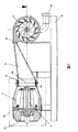
添付の図、特に図1および図2によれば、機械的エネルギー生成システムは、配向管(3)に相互接続される蒸気生成チャンバー(2)に接続されるガスタービン(1)により構成されるシングルブロック(single block)の複合サイクルを含み、前記配向管(3)の出口端は、少なくとも1つの蒸気タービン(4)と連通する。
To facilitate an understanding of the components of the energy generation system and its aspects according to the present invention, the reference numbers are not necessarily repeated in every figure, since it complicates the understanding of some details shown in the figures.
According to the attached figures, in particular FIGS. 1 and 2, the mechanical energy generation system consists of a gas turbine (1) connected to a steam generation chamber (2) interconnected to an orientation tube (3). Including a single block combined cycle, the outlet end of the orientation tube (3) is in communication with at least one steam turbine (4).
この好ましい態様において、機械的エネルギー生成システムは、支持基盤(5)上に設置され、任意の目的のためのモジュラーエネルギー(modular energy)を生成することが可能な電気ジェネレーター(6)に連結される。
また、図1および図2を参照して、シングルブロック内の前記複合サイクルの流れを見ることができ、ここでは空気を捕らえることから始まり、その空気はガスタービン(1)の入り口開口(11)に取り入れられ、燃焼チャンバー(7)内の供給ノズル(12)により噴射される燃料と混合され、パワータービン(13)中で膨張される高温のガスを生成する。
In this preferred embodiment, the mechanical energy generation system is mounted on a support base (5) and is connected to an electric generator (6) capable of generating modular energy for any purpose. .
1 and 2, the flow of the combined cycle in a single block can be seen, where it begins by capturing air, which is the inlet opening (11) of the gas turbine (1). And is mixed with fuel injected by a supply nozzle (12) in the combustion chamber (7) to produce hot gases that are expanded in the power turbine (13).
前記パワータービン(13)は、水噴射機構(14)を装備した蒸気生成チャンバー(2)の方向に、ガスタービン(1)からの熱いガスの排出を引き起こす。水は前記蒸気生成チャンバー(2)に入り、燃焼チャンバー(7)、ガスタービン(1)からのガスエネルギーが、噴射された水の瞬間的な気化を推進し、結果的として蒸気の流れを得る。配向管(3)により導かれる燃焼ガスと混合されるため、これは汚染または損失蒸気と名づけられる。
前記配向管(3)は、蒸気タービン(4)の吸気口(15)の方向に、汚染蒸気の流れを導く目的がある。前記配向管(3)の特徴は、蒸気タービン(4)のパワーおよびサイズによって決まり得ることを強調しておくことは重要である。例えば、前記配向管(3)は、タービンのいくつかの部に蒸気を供給するための一定の断面を有し得るが、またディフューザーに似た変化する断面を提供し得る。
The power turbine (13) causes the discharge of hot gas from the gas turbine (1) in the direction of the steam generation chamber (2) equipped with a water injection mechanism (14). Water enters the steam generation chamber (2) and gas energy from the combustion chamber (7), gas turbine (1) drives the instantaneous vaporization of the injected water, resulting in a steam flow. . Since it is mixed with the combustion gas introduced by the orientation tube (3), it is termed contaminated or lost steam.
The orientation pipe (3) has the purpose of guiding the flow of contaminated steam in the direction of the inlet (15) of the steam turbine (4). It is important to emphasize that the characteristics of the orientation tube (3) may depend on the power and size of the steam turbine (4). For example, the orientation tube (3) may have a constant cross-section for supplying steam to some parts of the turbine, but may also provide a varying cross-section similar to a diffuser.
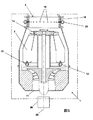
あるいは、図2に示される態様において示されるように、前記配向管(3)内に、誘導ディフューザー(16)を導入することが可能であり、その目的は、蒸気タービン(4)の入り口への蒸気の流れをガイドすることにある。前記ディフューザーは蒸気の流れをタービンの入り口へバランス良く向けることができるため、1以上の蒸気タービン(4)の組合せがある場合には、このディフューザー(16)の配置が特に有益である。
蒸気タービン(4)は、好ましくは、隣り合わせに配置され互いに比較的小さな距離に置かれる一連の並行ディスク(8)により形成され、配向管(3)を通り抜ける汚染蒸気が、前記並行ディスク(8)の接線方向に位置する吸気口(15)へ導入される。
Alternatively, as shown in the embodiment shown in FIG. 2, it is possible to introduce an induction diffuser (16) into the orientation tube (3), the purpose of which is to the inlet of the steam turbine (4) It is to guide the flow of steam. The arrangement of the diffuser (16) is particularly beneficial when there is a combination of one or more steam turbines (4) since the diffuser can direct the steam flow to the turbine inlet in a well-balanced manner.
The steam turbine (4) is preferably formed by a series of parallel disks (8) arranged side by side and placed at a relatively small distance from each other, and the contaminated steam passing through the orientation tube (3) is said parallel disk (8). To the intake port (15) located in the tangential direction.
よって、汚染蒸気の流れは、中央通路へ放出さるまで、ディスク(8)間の空間でその表面を介して、ディスク(8)の端部に接線方向に導入される。この高温、高圧の蒸気の流れを介して、シャフト(10)はディスクの動きを保持し、その結果として前記シャフト(10)の端(10’)において、機械的なエネルギーを生成する。
好ましい態様では、並行ディスク(8)の中央領域からの蒸気の出口は、通常濃縮された蒸気を生成する排気口(17)の方向に向けられ得る。
Thus, the flow of contaminated vapor is introduced tangentially to the end of the disc (8) via its surface in the space between the discs (8) until it is discharged into the central passage. Through this high-temperature, high-pressure steam flow, the shaft (10) retains the movement of the disc, resulting in the generation of mechanical energy at the end (10 ') of the shaft (10).
In a preferred embodiment, the outlet of the steam from the central region of the parallel disk (8) can be directed in the direction of the outlet (17), which normally produces concentrated steam.
別の態様では、図3および4に示されるように、前記排気口(17)はフィルタリングシステムに、または、凝縮(condenser)および分離デバイス(21)にも連結され、分離デバイスは、ガス出口チューブ(22)および水出口(23)を含み、後者はパイプ(24)によって水噴射機構(14)に接続され、濃縮された水の再利用を可能にする。
前記凝縮および分離デバイス(21)は、残りの蒸気を濃縮し、まだ水に溶解されている燃焼ガスの物理的な分離を可能にする目的がある。熱湯または冷水は、蒸気生成チャンバー内の水噴射機構(14)に戻り、燃焼ガスはガス出口チューブ(22)によって、大気に解放される。
In another aspect, as shown in FIGS. 3 and 4, the outlet (17) is connected to a filtering system or to a condenser and separation device (21), the separation device comprising a gas outlet tube (22) and a water outlet (23), the latter being connected to the water injection mechanism (14) by a pipe (24), allowing the reuse of the concentrated water.
Said condensation and separation device (21) is intended to concentrate the remaining vapor and to allow physical separation of the combustion gases still dissolved in water. Hot or cold water returns to the water injection mechanism (14) in the steam generation chamber, and the combustion gas is released to the atmosphere by the gas outlet tube (22).
図5に関して、水噴射機構(14)が装備された蒸気生成チャンバー(2)に連結されるガスタービン(1)が示される。この図においては、チャネル(20)により供給される半径方向に配置された複数のインジェクターノズル(19)を備えたリング(18)を含む、前記水噴射機構(14)の好ましい態様が示される。当業者により評価されるように、前記インジェクターノズル(19)の量および寸法は、システムプロジェクトの全体としての特徴に依存する。
図6Aおよび6Bは、一連の並行ディスク(8)を含む、蒸気タービン(3)の好ましい態様のいくつかの詳細を示し、一連の並行ディスク(8)は、図6Bに示されるように、隣り合わせに配置され、蒸気の流れる通路を形成するためにそれらの間に空間が設けられる。
With reference to FIG. 5, a gas turbine (1) connected to a steam generation chamber (2) equipped with a water injection mechanism (14) is shown. In this figure, a preferred embodiment of the water injection mechanism (14) is shown, including a ring (18) with a plurality of radially arranged injector nozzles (19) supplied by a channel (20). As will be appreciated by those skilled in the art, the amount and size of the injector nozzle (19) will depend on the overall characteristics of the system project.
6A and 6B show some details of a preferred embodiment of the steam turbine (3), including a series of parallel disks (8), the series of parallel disks (8) being side-by-side as shown in FIG. 6B. And a space is provided between them to form a passage through which steam flows.
特に図6Aに関して、蒸気タービン(4)のディスク(8)の構造の別の態様を観察することができる。本発明の好ましい態様において、リミットレイヤー効果および並行ディスクの側面の1つの半径方向に位置するペルトンタイプのブレードにより生成される効果の組合せを可能にするために、前記蒸気タービン(3)は、ペルトン効果ブレードを備えるテスラタービンタイプである。示されるように、ディスク(8)の表面は、ペルトン効果と名づけられるディスク(8)の端および中央の間の蒸気の流れの伝導を補助するアーチ形状または任意の他の形状のいくつかのブレード(9)が装備される。 With particular reference to FIG. 6A, another aspect of the structure of the disk (8) of the steam turbine (4) can be observed. In a preferred embodiment of the invention, in order to allow a combination of the limit layer effect and the effect produced by one radially located Pelton type blade on the side of the parallel disk, the steam turbine (3) Tesla turbine type with effect blades. As shown, the surface of the disk (8) has several blades of arch shape or any other shape that assists in the conduction of steam flow between the end and center of the disk (8), termed the Pelton effect (9) is equipped.
当業者によく知られるように、並行ディスクを備える蒸気タービンは、テスラタービンとして知られ、そのディスクは平らな表面を含む。別の、そしてまた有利な態様では、並行ディスクおよびスピードとトルクの改善を得るためのブレードを備えたディスクを組み合わせることも可能であり、それは、開発されるシステム、本発明の目的のための目標および応用に依存する。
最後に、本発明のエネルギー生成システムは、効率の改善、タービンの温度の減少、およびNOx排出の減少を得ることを可能にするために、再生サイクルおよび水噴射、もしくは燃焼チャンバーまたはコンプレッサーの吸気口への蒸気のような、ガスタービンに従来利用されるサイクルおよびプロセスを含んでもよい。
As is well known to those skilled in the art, a steam turbine with parallel disks is known as a Tesla turbine, which includes a flat surface. In another and also advantageous aspect, it is also possible to combine parallel disks and disks with blades to obtain speed and torque improvements, which is a system developed, a goal for the purposes of the present invention. And depends on the application.
Finally, the energy generation system of the present invention provides a regeneration cycle and water injection, or combustion chamber or compressor inlet to allow improved efficiency, reduced turbine temperature, and reduced NOx emissions. It may include cycles and processes conventionally used in gas turbines, such as steam to.
本発明は、タービンの2つの異なるシャフトにおいて、とても高いエネルギーを同時に生成することができる技術的および機能的特徴を含む、複合サイクルタイプのエネルギー生成システムに関する。以下に詳細に説明されるが、端的には、本発明によるシステムは、蒸気ジェネレーターチャンバーに連結されるガスタービンの組合せにより構成され、前記蒸気ジェネレーターチャンバーは、汚染蒸気を扱うタービンに順々に連結される。1つの態様において、このタービンは、ペルトン効果(Pelton effect)を備えるテスラタービン(Tesla turbine)のようなディスクタービンである。 The present invention relates to a combined cycle type energy generation system including technical and functional features that can simultaneously generate very high energy in two different shafts of a turbine. As will be explained in detail below, in short, the system according to the invention consists of a combination of gas turbines connected to a steam generator chamber, which in turn are connected to a turbine handling contaminated steam. Is done. In one embodiment, the turbine is a disk turbine, such as a Tesla turbine with a Pelton effect.
当業者によく知られているように、機械的なエネルギーを得る方法、および同様にそこから電気的なエネルギーを生成する方法は数多く存在する。いくつかの方法の中にも、エネルギー生成に関与する多くのモデルの装置およびシステムがあり、それらは一見すると現在のニーズを満たしているようだが、長期的には、例えばエネルギー生成によく利用される天然源の不足のような、人類の生活を危うくする特定の問題が明らかになっている。 As is well known to those skilled in the art, there are many ways to obtain mechanical energy, as well as to generate electrical energy therefrom. There are many models of devices and systems that are involved in energy generation, amongst other methods, which seem to meet current needs at first glance, but in the long run they are often used for energy generation, for example. Certain problems have been identified that endanger human life, such as lack of natural resources.
蒸気生成に関しては、燃焼による熱の生成を得るために、過剰に燃料(バイオマス、ガス、オイル、および他の可燃性の液体)を消費する従来型のボイラーが数十年間も利用されてきた。これらのボイラーは、水の流れを基にした熱交換器から成り、水は気化するまで熱せられ、飽和状態または過熱状態の蒸気となる。その工程に利用される水の質はとても高い必要がある。蒸気にいくつかの不純物が見つかる場合、蒸気タービンに深刻な損傷が与えられるので、脱塩水および高純度の水のみが利用可能である。この水の脱塩工程には高いコストが伴うため、この種類のエネルギー生成工程は非常に費用がかかる。
前述の飽和状態または過熱状態の蒸気は貯留槽に向けられ、従来の蒸気タービンでの利用のために必要な圧力および温度に至るまで貯留槽内に蓄積される。必要な圧力および温度に至るまで、大量の蒸気が蓄積されなければならない。これには大きな貯留槽が利用される必要がある。
With regard to steam generation, conventional boilers that consume excessive fuel (biomass, gas, oil, and other flammable liquids) have been used for decades to obtain heat generation from combustion. These boilers consist of heat exchangers based on the flow of water, where the water is heated until it vaporizes, becoming saturated or superheated steam. The quality of water used in the process needs to be very high. If some impurities are found in the steam, serious damage will be done to the steam turbine, so only demineralized water and high purity water are available. This type of energy generation process is very expensive because the water desalting process involves high costs.
The saturated or superheated steam described above is directed to the reservoir and is accumulated in the reservoir up to the pressure and temperature required for use in a conventional steam turbine. Large amounts of vapor must accumulate until the required pressure and temperature are reached. This requires the use of large reservoirs.
したがって、認められるように、このタイプの装置およびシステムは、効率性、敏捷性、燃料の損失、水質、コスト、および物理的な空間に関する一連の不都合が明らかになっている。さらに具体的には、以下のものが認められる:
i)熱交換器内の大量の水を熱するにはとても長い時間がかかり、燃料の過剰な消費をもたらす。
ii)水が気化温度に達するまでに生成および利用されたすべての熱が失われ、燃料を損失する。
iii)ボイラーは大きく、相当の物理的な空間を占め、複雑で高額な取り付けが必要になる。
iv)ボイラーは水流の問題を示す。
Thus, as can be appreciated, this type of device and system has revealed a series of inconveniences regarding efficiency, agility, fuel loss, water quality, cost, and physical space. More specifically, the following are allowed:
i) Heating a large amount of water in the heat exchanger takes a very long time, resulting in excessive consumption of fuel.
ii) All the heat generated and used by the time the water reaches the vaporization temperature is lost and fuel is lost.
iii) Boilers are large and occupy considerable physical space and require complex and expensive installations.
iv) Boilers show water flow problems.
したがって、最先端として知られるエネルギー生成システムの装置および機械が、いわば直接的、間接的に環境を危険にさらす、主に蒸気生成工程において、効率性、パワー、生産量、および敏捷性に関連するいくつかの不都合および制限を示すことは明らかである。
したがって、燃料エネルギーをさらに有利な方法において利用、または、他の工程から得られる熱を熱源として利用するようなシステムの発展は興味深い。この状況において、工程はランキンサイクルとして知られ、ブレイトンサイクルと組み合わされて、複合サイクルと呼ばれる。
Thus, energy generation system devices and machines, known as state-of-the-art, are directly related to efficiency, power, yield, and agility, primarily in the steam generation process, which directly and indirectly endanger the environment. Obviously, some disadvantages and limitations are shown.
Therefore, it is interesting to develop a system that uses fuel energy in a more advantageous manner or uses heat from other processes as a heat source. In this situation, the process is known as the Rankine cycle and is combined with the Brayton cycle and is called the combined cycle.
ガスタービンは、コンプレッサー、燃焼チャンバーおよびフォースタービン(force turbine)の3つの装置の組合せを含み得る。この装置はオープンサイクルで動くため、作動流体(空気)は、大気圧力条件化および脱出ガスに入れられ、フォースタービンを通った後に、吸気口に戻ることなく周囲に排出される。
最先端のものとして、ガスタービンを熱源として利用し、蒸気タービンを第二タービンとして利用する複合サイクルのプラントが知られている。これらのプラントにおいて、ガスタービン内の燃料燃焼により生成される熱は、管の中を流れる水を熱するために利用される。これらのプラントにおいて、蒸気は燃焼ガスと混合されることなく形成され、利用される蒸気タービンは不純物のある蒸気の利用を認めないため、水質もまた高純度でなければならない。したがって、これらの種類のプラントもまた高額である。
The gas turbine may include a combination of three devices: a compressor, a combustion chamber, and a force turbine. Since this device operates in an open cycle, the working fluid (air) is placed in atmospheric pressure conditioning and escape gas, and after passing through the force turbine, is discharged to the surroundings without returning to the inlet.
As a state-of-the-art, a combined cycle plant using a gas turbine as a heat source and a steam turbine as a second turbine is known. In these plants, the heat generated by fuel combustion in the gas turbine is utilized to heat the water flowing through the tubes. In these plants, the water must also be of high purity since the steam is formed without being mixed with the combustion gases and the steam turbine utilized does not allow the use of impure steam. Therefore, these types of plants are also expensive.
最先端のものとして、ガスタービンを熱源として利用し、ガスタービンを第二タービンとして利用する複合サイクルのプラントが、ドイツの先行技術DE3619661として示されている。この文献に示されているシステムにおいて、ガスタービン内で形成されたガスは、水と混合され汚染蒸気を形成する。しかしながら、この汚染蒸気は、ガスタービンの動作条件として過熱されなければならない。これは、生成された汚染蒸気が高温および圧力状況にあり、またすべての導管および装置が、これら幾つかの動作条件に耐え得る必要があることを意味する。一般的には、これらのシステムは、高圧および温度条件に耐えるために、特別で高額な合金から構成されなければならず、この種類のプラントもまたとても高額になる。
したがって、動作のための高純度の蒸気の利用の必要がなく、低建設コストであり、燃料の損失がなく、大量のエネルギーを生成する、複合サイクルシステムの発展は興味深い。
As a state-of-the-art, a combined cycle plant that uses a gas turbine as a heat source and a gas turbine as a second turbine is shown as German prior art DE 3619661. In the system shown in this document, the gas formed in the gas turbine is mixed with water to form contaminated vapor. However, this contaminated steam must be overheated as a gas turbine operating condition. This means that the generated contaminated vapor is in high temperature and pressure conditions and that all conduits and equipment must be able to withstand these several operating conditions. In general, these systems must be constructed from special and expensive alloys to withstand high pressure and temperature conditions, and this type of plant is also very expensive.
It is therefore interesting to develop combined cycle systems that do not require the use of high purity steam for operation, have low construction costs, no fuel loss, and generate large amounts of energy.
したがって、上記に示された問題に照らして、ガスタービンに連結されるジェネレーターを含む複合サイクルシステムが示され、このガスタービンは蒸気生成チャンバーに連結されて一体構造の機器を形成し、前記一体構造の機器は、
汚染蒸気と共に動作するタービンに導管を介して連結され、第二タービンおよびガスタービンは異なるシャフトにある。
ガスタービンおよび第二タービンの異なるシャフトは、同期した態様で動作する必要がないためジェネレーターの連結を結局は簡単にするので、システムに構造的な利点をもたらす。
Thus, in light of the problems indicated above, a combined cycle system is shown that includes a generator coupled to a gas turbine, the gas turbine coupled to a steam generation chamber to form a unitary structure, said unitary structure The equipment of
Connected via a conduit to a turbine operating with contaminated steam, the second turbine and the gas turbine are on different shafts.
The different shafts of the gas turbine and the second turbine do not have to operate in a synchronized manner and ultimately simplify the connection of the generators, thus providing a structural advantage to the system.
1つの態様では、ガスタービンシャフトと第二タービンシャフトとは垂直である。
1つの態様では、気化チャンバーは、ガスタービンの端に連結され、チャンバーの中央のリングには水インジェクターが配置される。
ここに開示されたシステムの利点は、フォースタービンを出るガスのエネルギーが、蒸気チャンバー内に噴射される水を気化するために利用されることにあり、大量の汚染蒸気が瞬間的に形成され、汚染蒸気と共に動き機械的なエネルギーが生成されるタービンに導かれる。
In one aspect, the gas turbine shaft and the second turbine shaft are vertical.
In one aspect, the vaporization chamber is connected to the end of the gas turbine, and a water injector is disposed in the central ring of the chamber.
The advantage of the system disclosed here is that the energy of the gas leaving the force turbine is used to vaporize the water injected into the steam chamber, and a large amount of contaminated vapor is formed instantaneously, It moves with the contaminated steam and is directed to a turbine where mechanical energy is generated.
1つの態様では、ここで開示された複合サイクルシステムの汚染蒸気と共に動くタービンは、テスラタービンを含む。
1つの態様では、ここで開示された複合サイクルシステムの汚染蒸気と共に動くタービンは、テスラ−ペルトンタービンを形成するペルトン隆起を含む変形テスラタービンを含む。
ここに開示されたシステムにおいて観察される利点は、それが、温度および圧力条件として従来当業者に知られているようなガスタービンを第二タービンとして利用する複合サイクルプラントに見られる程には極端ではない、条件で動くことである。
In one aspect, the turbine moving with the contaminated steam of the combined cycle system disclosed herein comprises a Tesla turbine.
In one aspect, a turbine that moves with the contaminated steam of the combined cycle system disclosed herein includes a modified Tesla turbine that includes a Pelton ridge that forms a Tesla-Pelton turbine.
The advantages observed in the system disclosed herein are so extreme that they are found in combined cycle plants that utilize a gas turbine as a second turbine, as known to those skilled in the art as temperature and pressure conditions. It is not, but it moves under conditions.
ここに開示されたシステムにおいて観察される他の利点は、ガスタービンを第二タービンとして含む複合サイクルプラントに利用される特殊で高価な合金を利用する必要がないため、構造が低コストであることである。
ここに開示されたシステムにおける他の有利な構成は、効果的な方法で大量の機械的なエネルギーを効果的に提供することに加えて、燃料の損失を実質的に削減する、機械的エネルギー生成システムにある。
ここに開示されたシステムは、一態様において電気的エネルギー生成システムに連結される、機械的エネルギー生成システムを提供する目的がある。
ここに開示されたシステムは、もうひとつの態様において、電気エネルギーとは異なるある種のエネルギーを生成するために生成された機械的エネルギーを使用する。
Another advantage observed in the system disclosed herein is the low cost of construction because there is no need to use special and expensive alloys used in combined cycle plants that include a gas turbine as a second turbine. It is.
Another advantageous configuration in the system disclosed herein is mechanical energy generation that substantially reduces fuel loss in addition to effectively providing large amounts of mechanical energy in an effective manner. In the system.
The system disclosed herein is intended to provide a mechanical energy generation system that, in one aspect, is coupled to an electrical energy generation system.
The system disclosed herein, in another aspect, uses mechanical energy generated to generate some type of energy that is different from electrical energy.
以下に開示された情報は、ここに開示された複合サイクルシステムに関する基本的な情報を構成する。
以下に示された例は、ここに開示された複合サイクルシステムのいくつかの可能性のある具体化を含み、いくつかの他の種類が可能であるため、具体化の形の制限を構成するものではない。
“汚染蒸気”という表現は、この文章においては、任意の比率の蒸気および汚染ガスの混合物として扱われる。
The information disclosed below constitutes basic information about the combined cycle system disclosed herein.
The examples presented below include some possible implementations of the combined cycle system disclosed herein, and constitute some limitations on the form of implementation since several other types are possible It is not a thing.
The expression “contaminated vapor” is treated in this text as a mixture of any proportion of vapor and contaminated gas.
したがって、ここに開示された機械的エネルギー生成システムは、水とガスタービンからの燃焼により生成されるガスの混合物から蒸気を得ることが可能な蒸気生成チャンバーを用いて、低圧力および低温度条件で動くタービンに接続されるガスタービンを含む。このガスタービンに取り付けられるものとして、ここに開示されるシステムはジェネレーターを含む。
1つの態様では、このジェネレーターはガスタービンのシャフトに直接取り付けられる。
1つの態様では、このジェネレーターはスキッドベース(skid base)の下にあり、コネクションを用いてガスタービンシャフトに接続される。
Accordingly, the mechanical energy generation system disclosed herein uses a steam generation chamber capable of obtaining steam from a mixture of water and gas produced by combustion from a gas turbine, at low pressure and temperature conditions. Including a gas turbine connected to a moving turbine. As attached to the gas turbine, the system disclosed herein includes a generator.
In one aspect, the generator is directly attached to the shaft of the gas turbine.
In one aspect, the generator is under a skid base and is connected to the gas turbine shaft using a connection.
ガスタービンは通常、ブレイトンサイクルとして知られる熱力学サイクルを基にした、オープンサイクルで動作する。これは、作動流体(空気)が大気圧で入れられ、コンプレッサー内で圧縮され、後にそこで燃焼も起こる、燃焼チャンバー内で燃料と混合される。この方法で生成されたガスは混合され、膨張を経て、タービンを通過した後に大気に放出される。このタイプのサイクルは、ガスタービンによって実行され、パワータービン内で1000〜13000℃程度のピークに至る、とても高い温度の獲得をその不可欠な特性の1つとして示す。さらにそれはパワーの生成ができるとともに、パワータービンの後端において500〜650℃程度の温度を伴うガスを放散する。 Gas turbines typically operate in an open cycle based on a thermodynamic cycle known as the Brayton cycle. This is mixed with fuel in a combustion chamber where the working fluid (air) is introduced at atmospheric pressure, compressed in a compressor, where combustion also occurs later. The gas produced in this way is mixed, expanded, and released to the atmosphere after passing through the turbine. This type of cycle is performed by a gas turbine and exhibits as one of its essential properties the acquisition of very high temperatures leading to peaks in the power turbine on the order of 1000-13000 ° C. Furthermore, it can generate power and dissipate gas with a temperature of about 500-650 ° C. at the rear end of the power turbine.
ここに開示されるシステムにおいて、蒸気生成チャンバーはガスタービンのフォースタービンのガス出口に連結され、これら燃焼ガス内の温度条件および含まれるエネルギーのために、このチャンバーに噴射される水の気化は瞬間的である。
本発明の1つの態様において、蒸気生成チャンバーは、ガスタービンのパワータービンの後に接続され、水粒子の接触が瞬時の気化を提供して燃焼ガスと混合される蒸気を生成するように、ガスタービンにより放出される高温ガスの流れの中に向けて水を注入する、インジェクター機構を含む。
In the system disclosed herein, the steam generation chamber is connected to the gas outlet of the force turbine of the gas turbine, and due to the temperature conditions and the energy contained within these combustion gases, the vaporization of the water injected into this chamber is instantaneous. Is.
In one aspect of the present invention, the steam generation chamber is connected after the power turbine of the gas turbine so that the contact of water particles provides instantaneous vaporization to generate steam that is mixed with the combustion gas. An injector mechanism for injecting water into the hot gas stream released by
1つの態様において、前記噴射機構は、気化チャンバー内で気化される水を噴射するノズルである。
1つの態様において、前記インジェクター機構は、その周囲に分散された複数のスプレーノズルが提供されるリング形状を含む。
生成された蒸気は、配向管により汚染蒸気と共に動くタービンの方向に導かれる。前記配向管は、入り口の寸法およびこのタービンの特徴によって決まる、ディフューザー形状内の一定または変化する断面を示すことが強調される。さらに言えば、前記配向管は、蒸気の流れの伝導および方向が、汚染蒸気と共に動くタービン上に効果的に同じように集束するように補助する中央ディフューザーを含み得る。
In one aspect, the said injection mechanism is a nozzle which injects the water vaporized within a vaporization chamber.
In one aspect, the injector mechanism includes a ring shape provided with a plurality of spray nozzles distributed around it.
The generated steam is guided by an orientation tube in the direction of the turbine that moves with the contaminated steam. It is emphasized that the orientation tube exhibits a constant or varying cross section within the diffuser shape, depending on the inlet dimensions and the characteristics of this turbine. More specifically, the orientation tube may include a central diffuser that assists the conduction and direction of the steam flow to be effectively focused in the same manner on the turbine moving with the contaminated steam.
1つの態様では、前記汚染蒸気と共に動くタービンは、例えばテスラタービンタイプのように、とても小さな距離に離されて配置された比較的小さな厚みの並行ディスクの配列を含むタイプのものである。これら並列ディスクは、シャフトに取り付けられて固定されたローターを形成し、固定子(stator)を形成するボックスなど円筒状の外側カバーに収容される。このタービンの目的は、様々な目的のために利用することができる機械的エネルギーを生成するためのシャフトを回転させることである。
1つの態様では、その特性の観点から、前記生成された機械的エネルギーは、本発明のシステムが電気ジェネレーターに連結された場合に、とても上手く応用できる。
In one aspect, the turbine that moves with the contaminated steam is of a type that includes an array of parallel disks of relatively small thickness arranged at very small distances, such as the Tesla turbine type. These parallel disks are attached to a shaft to form a fixed rotor, and are accommodated in a cylindrical outer cover such as a box that forms a stator. The purpose of this turbine is to rotate a shaft to generate mechanical energy that can be utilized for various purposes.
In one embodiment, in view of its properties, the generated mechanical energy can be applied very well when the system of the present invention is connected to an electric generator.
テスラタイプのような、並行ディスクを備えるタービンの特徴は、蒸気が、その中でディスクの端から蒸気が排気口から抜ける中央に向けて流れる蒸気ローターを動かす作動流体(work fluid)を利用する動作原理を持つ。テスラタイプタービンの利点の一つは、低圧力および低温度を含む任意の条件で蒸気を利用し、先述の汚染蒸気のような、それが燃焼ガスと共に混合される蒸気によって動作可能であるという能力にある。 Features of turbines with parallel disks, such as the Tesla type, use a working fluid that moves a steam rotor in which steam flows from the end of the disk toward the center where steam exits through the exhaust. Has a principle. One of the advantages of Tesla type turbines is the ability to utilize steam at any condition, including low pressure and temperature, and that it can be operated with steam mixed with combustion gases, such as the aforementioned contaminated steam It is in.
1つの態様では、ディスクタービンのディスクの最適な組合せに関しては、それらのいくつか、またはそれらのすべては、前記プレート(plates)間の作動流体の流れの伝達と通過を促進および補助するチャネル(channel)を形成するように、平らではない構造を含む。したがって、ここに開示されるシステムの1つの態様において、タービンディスクがペルトンバック(pelton bucks)に類似した湾曲構造の隆起を含む、ペルトン効果を含むタイプのテスラタービンであって、その機能は、ディスク表面への境界層限界接着効果(the boundary layer limit adherence effect)を増加し、シャフトの回転を起すトルク表面(torque surface)を提供することである。したがって、蒸気生成チャンバーと組み合わされるガスタービンを介した蒸気生成によって、ローターのシャフトにおいて高レベルの機械的エネルギーを生成するように、汚染蒸気と共に動くタービン内に適用される理想特性を備えた蒸気を高効率に得ることができる。 In one aspect, with respect to the optimal combination of disks of a disk turbine, some or all of them are channels that facilitate and assist in the transfer and passage of working fluid flow between the plates. ) To form a structure that is not flat. Accordingly, in one aspect of the system disclosed herein, a Tesla turbine of the type that includes a Pelton effect, in which the turbine disk includes curved structural ridges similar to pelton bucks, the function of which is To increase the boundary layer limit adherence effect to the surface and to provide a torque surface that causes shaft rotation. Therefore, steam with ideal characteristics applied in a turbine moving with contaminated steam, so that steam generation through a gas turbine combined with a steam generation chamber generates a high level of mechanical energy in the rotor shaft. High efficiency can be obtained.
リカバリーボイラーよりさらにコンパクトになることに加えて、蒸気生成チャンバーに連結されるガスタービンを利用する主な利点の一つは、要求および所望の条件の量、圧力、および動作実行のための蒸気温度で、瞬時に蒸気を生成すること、およびタービンのシャフトからパワーを生成することであることが強調される。
先に示されたように、本発明の機械的エネルギー生成システムは、高い生産量および低い製造コストを伴うエネルギー生成ステーションを得るために、電気ジェネレーターに連結する場合に大きな適用性を示す。1つの態様において、前記電気ジェネレーターは、スキッドタイプのシングルベース(single base of type skid)の本発明によるシステムに連結される。
In addition to being more compact than a recovery boiler, one of the main advantages of utilizing a gas turbine coupled to a steam generation chamber is the amount of required and desired conditions, pressure, and steam temperature to perform the operation. It is emphasized that it is producing steam instantaneously and generating power from the turbine shaft.
As previously indicated, the mechanical energy generation system of the present invention has great applicability when coupled to an electric generator to obtain an energy generation station with high production volume and low manufacturing costs. In one embodiment, the electric generator is coupled to a system according to the invention of a single base of type skid.
1つの態様では、本発明のシステムをさらに経済的にするために、分離凝縮デバイス(separator condenser device)を連結することも可能であり、その目的は、前記汚染蒸気と共に動くタービンの排気口を介して出て行くガスおよび水を捕らえて、蒸気生成チャンバー内の水インジェクター機構(water injector mechanism)によって再利用するための後者を導くために、水からガスを分離することにある。
また、1つの態様においては、ペルトン効果ブレードを備えるテスラタイプ等の汚染蒸気と共に動くタービンの出口からの流体内に残る余剰熱を活用し、それを再生サイクルからの水の加熱または他の熱応用に応用することが可能である。
In one aspect, a separator condenser device can be connected to make the system of the present invention more economical, the purpose of which is via a turbine outlet moving with the contaminated steam. It is in separating the gas from the water to capture the outgoing gas and water and direct the latter to be reused by a water injector mechanism in the steam generation chamber.
Also, in one aspect, excess heat remaining in the fluid from the exit of the turbine moving with contaminated steam, such as a Tesla type blade with a Pelton effect blade, is utilized to heat water from the regeneration cycle or other thermal application It is possible to apply to.
本発明の目的による機械的エネルギー生成システムの技術的効果および利点は、好ましい態様を説明するが本発明を限定するものではない添付の図を参照にして作られた以下の詳細から、当業者により明らかである。
本発明によるエネルギー生成システムの構成要素およびその態様の理解を促進するために、図に示されたいくつかの詳細の理解を複雑にすることから、参照番号はすべての図において必ずしも繰り返されない。
添付の図、特に図1および図2によれば、機械的エネルギー生成システムは、ジェネレーター(25)、一体で形成する蒸気生成チャンバー(2)に接続されるガスタービン(1)から成るシングルブロック(single block)の複合サイクルを含み、前記ジェネレーター(25)は、ガスタービンのシャフトに接続される。蒸気チャンバー生成の端は配向管(3)に相互接続され、配向管の出口端は、汚染蒸気(4)と共に動く少なくとも1つのタービンと連通する。
To facilitate an understanding of the components of the energy generation system and its aspects according to the present invention, the reference numbers are not necessarily repeated in every figure, since it complicates the understanding of some details shown in the figures.
According to the accompanying figures, in particular FIGS. 1 and 2, the mechanical energy generation system comprises a single block (1) consisting of a generator (25), a gas turbine (1) connected to an integrally formed steam generation chamber (2). The generator (25) is connected to the shaft of a gas turbine. The end of the steam chamber generation is interconnected to the orientation tube (3), and the exit end of the orientation tube communicates with at least one turbine that moves with the contaminated steam (4).
この態様において、機械的エネルギー生成システムは、支持基盤(5)の上に設置される。
また、図1および図2を参照して、シングルブロック内の前記複合サイクルの流れを見ることができ、ここでは空気を捕らえることから始まり、その空気はガスタービン(1)の入り口開口(11)に取り入れられ、燃焼チャンバー(7)内の供給ノズル(12)により注入される燃料と混合され、パワータービン(13)中で膨張される高温のガスを生成する。パワータービン(13)に取り付けられる、電気的エネルギーを生成するジェネレーター(25)がある。
In this embodiment, the mechanical energy generation system is installed on the support base (5).
1 and 2, the flow of the combined cycle in a single block can be seen, where it begins by capturing air, which is the inlet opening (11) of the gas turbine (1). And is mixed with fuel injected by a supply nozzle (12) in the combustion chamber (7) to produce hot gas that is expanded in the power turbine (13). There is a generator (25) that produces electrical energy attached to the power turbine (13).
前記パワータービン(13)は、水噴射機構(14)を装備した蒸気生成チャンバー(2)の方向に、ガスタービン(1)からの熱いガスの排出を引き起こす。水は前記蒸気生成チャンバー(2)に入り、燃焼チャンバー(7)、ガスタービン(1)からのガスエネルギーが、注入された水の瞬間的な気化を推進し、結果的として蒸気の流れを得る。配向管(3)により導かれる燃焼ガスと混合されるため、これは汚染または損失蒸気と名づけられる。
前記配向管(3)は、第二タービン(4)の流体入口(15)の方向に、汚染蒸気の流れを導く目的がある。第二タービン(4)に取り付けられる、電気的エネルギーを生成する第二ジェネレーター(6)がある。
The power turbine (13) causes the discharge of hot gas from the gas turbine (1) in the direction of the steam generation chamber (2) equipped with a water injection mechanism (14). Water enters the steam generation chamber (2) and gas energy from the combustion chamber (7), gas turbine (1) drives the instantaneous vaporization of the injected water, resulting in a steam flow. . Since it is mixed with the combustion gas introduced by the orientation tube (3), it is termed contaminated or lost steam.
The orientation tube (3) has the purpose of directing the flow of contaminated vapor in the direction of the fluid inlet (15) of the second turbine (4). There is a second generator (6) that generates electrical energy attached to the second turbine (4).
前記配向管(3)の特徴は、タービン(4)のパワーおよびサイズによって決まり得ることを強調しておくことは重要である。例えば、前記配向管(3)は、タービンのいくつかの部に蒸気を供給するための一定の断面を有し得るが、またディフューザーに似た変化する断面を提供し得る。
あるいは、図2に示される態様において示されるように、前記配向管(3)内に、誘導ディフューザー(16)を導入することが可能であり、その目的は、タービン(4)の入り口への蒸気の流れをガイドすることにある。前記ディフューザーは蒸気の流れをタービンの入り口へバランス良く向けることができるため、1以上のタービン(4)の組合せがある場合には、このディフューザー(16)の配置が特に有益である。
It is important to emphasize that the characteristics of the orientation tube (3) can depend on the power and size of the turbine (4). For example, the orientation tube (3) may have a constant cross-section for supplying steam to some parts of the turbine, but may also provide a varying cross-section similar to a diffuser.
Alternatively, as shown in the embodiment shown in FIG. 2, it is possible to introduce an induction diffuser (16) into the orientation tube (3), the purpose of which is to steam to the inlet of the turbine (4) Is to guide the flow of The arrangement of the diffuser (16) is particularly beneficial when there is a combination of one or more turbines (4) because the diffuser can direct the steam flow to the turbine inlet in a well-balanced manner.
1つの態様では、タービン(4)は、隣り合わせに配置され互いに比較的小さな距離に置かれる一連の並行ディスク(8)により形成され、配向管(3)を通り抜ける汚染蒸気が、前記並行ディスク(8)の接線方向に位置する流体入口(15)へ導入される。
よって、汚染蒸気の流れは、中央通路へ放出さるまで、ディスク(8)間の空間でその表面を介して、ディスク(8)の端部に接線方向に導入される。この汚染蒸気の流れを介して、ディスクは回転し、結果としてディスクを保持するシャフト(10)もまた回転し、その結果として前記シャフト(10)の端(10’)において、機械的なエネルギーを生成する。図2および4に見られるように、第二タービン(27)のシャフトおよびガスタービン(26)のシャフトは異なる。これは同期操作の不必要性を意味する。
In one aspect, the turbine (4) is formed by a series of parallel disks (8) arranged side by side and placed at a relatively small distance from each other, and the contaminated vapor passing through the orientation tube (3) is said parallel disk (8). ) To the fluid inlet (15) located in the tangential direction.
Thus, the flow of contaminated vapor is introduced tangentially to the end of the disc (8) via its surface in the space between the discs (8) until it is discharged into the central passage. Through this contaminated vapor flow, the disk rotates, and as a result the shaft (10) holding the disk also rotates, resulting in mechanical energy at the end (10 ') of the shaft (10). Generate. As can be seen in FIGS. 2 and 4, the shaft of the second turbine (27) and the shaft of the gas turbine (26) are different. This means that synchronization operations are unnecessary.
1つの態様では、並行ディスク(8)の中央領域からの蒸気の出口は、通常濃縮された蒸気を生成する排気口(17)の方向に向けられ得る。
もう1つの態様では、図3および4に示されるように、前記排気口(17)はフィルタリングシステム、または凝縮(condenser)および分離デバイス(21)にも連結され、分離デバイスは、ガス出口チューブ(22)および水出口(23)を含み、後者はパイプ(24)によって水噴射機構(14)に接続され、濃縮された水の再利用を可能にする。
In one aspect, the vapor outlet from the central region of the parallel disk (8) may be directed towards the exhaust (17) that normally produces concentrated vapor.
In another aspect, as shown in FIGS. 3 and 4, the outlet (17) is also connected to a filtering system, or a condenser and separation device (21), the separation device comprising a gas outlet tube ( 22) and a water outlet (23), the latter being connected to the water injection mechanism (14) by a pipe (24), allowing the reuse of the concentrated water.
前記凝縮および分離デバイス(21)は、残りの蒸気を濃縮し、まだ水に溶解されている燃焼ガスの物理的な分離を可能にする目的がある。熱湯または冷水は、蒸気生成チャンバー内の水噴射機構(14)に戻り、燃焼ガスはガス出口チューブ(22)によって、大気に解放される。
図5に関して、水噴射機構(14)が装備された蒸気生成チャンバー(2)に連結されるガスタービン(1)が示される。この図においては、チャネル(20)により供給される半径方向に配置された複数のインジェクターノズル(19)を備えたリング(18)を含む、前記水噴射機構(14)の1つの態様が示される。当業者により評価されるように、前記インジェクターノズル(19)の量および寸法は、システムプロジェクトの全体としての特徴に依存する。
Said condensation and separation device (21) is intended to concentrate the remaining vapor and to allow physical separation of the combustion gases still dissolved in water. Hot or cold water returns to the water injection mechanism (14) in the steam generation chamber, and the combustion gas is released to the atmosphere by the gas outlet tube (22).
With reference to FIG. 5, a gas turbine (1) connected to a steam generation chamber (2) equipped with a water injection mechanism (14) is shown. In this figure, one embodiment of the water injection mechanism (14) is shown including a ring (18) with a plurality of radially arranged injector nozzles (19) supplied by a channel (20). . As will be appreciated by those skilled in the art, the amount and size of the injector nozzle (19) will depend on the overall characteristics of the system project.
図6Aおよび6Bは、一連の並行ディスク(8)を含む、汚染蒸気(4)と共に動くタービンの1つの態様のいくつかの詳細を示し、一連の並行ディスク(8)は、図6Bに示されるように隣り合わせに配置され、汚染蒸気の流れる通路を形成するためにそれらの間に空間が設けられる。
特に図6Aに関して、タービン(4)のディスク(8)の構造の1つの態様を観察することができる。本発明の1つの態様において、リミットレイヤー効果および並行ディスクの側面の1つに位置する半径方向のペルトンタイプのブレードにより生成される効果の組合せを可能にするために、前記タービン(4)は、ペルトン効果隆起を備えるテスラタービンタイプである。示されるように、ディスク(8)の表面は、ペルトン効果と名づけられるディスク(8)の端および中央の間の蒸気の流れの伝導を補助する隆起アーチ形状または任意の他の形状のいくつかの構造体(9)が装備される。
6A and 6B show some details of one aspect of a turbine that moves with contaminated steam (4), including a series of parallel disks (8), the series of parallel disks (8) being shown in FIG. 6B. Are arranged next to each other, and a space is provided between them to form a passage through which contaminated vapor flows.
With particular reference to FIG. 6A, one aspect of the structure of the disk (8) of the turbine (4) can be observed. In one aspect of the invention, in order to allow a combination of the limit layer effect and the effect produced by radial Pelton type blades located on one of the sides of the parallel disk, the turbine (4) Tesla turbine type with Pelton effect ridges. As shown, the surface of the disk (8) has several raised arch shapes or some other shape that assists in the flow of steam between the edge and center of the disk (8), termed the Pelton effect. The structure (9) is equipped.
当業者によく知られるように、並行ディスクを備える一形式のタービンは、テスラタービンとして知られ、そのディスクは平らな表面を含む。
有利な態様では、並行ディスクおよびスピードとトルクの改善を得るための隆起したアーチを備えた変更ディスクを組み合わせることも可能であり、それは、開発されるシステム、本発明の目的のための目標および応用に依存する。
最後に、ここに開示されたエネルギー生成システムは、効率の改善、タービンの温度の減少、およびNOx排出の減少を得ることを可能にするために、再生サイクルおよび水噴射、もしくは燃焼チャンバーまたはコンプレッサーの吸気口への蒸気のような、ガスタービンに従来利用されるサイクルおよびプロセスを含んでもよい。
As is well known to those skilled in the art, one type of turbine with parallel disks is known as a Tesla turbine, which includes a flat surface.
In an advantageous manner, it is also possible to combine a parallel disk and a modified disk with raised arches to obtain speed and torque improvements, which is the system developed, the goals and applications for the purposes of the present invention. Depends on.
Finally, the energy generation system disclosed herein allows regeneration cycles and water injection, or combustion chambers or compressors to be able to obtain improved efficiency, reduced turbine temperature, and reduced NOx emissions. It may include cycles and processes conventionally utilized in gas turbines, such as steam to the inlet.
本発明は、タービンの2つの異なるシャフトにおいて、とても高いエネルギーを同時に生成することができる技術的および機能的特徴を含む、複合サイクルタイプのエネルギー生成システムに関する。以下に詳細に説明されるが、端的には、本発明によるシステムは、蒸気ジェネレーターチャンバーに連結されるガスタービンの組合せにより構成され、前記蒸気ジェネレーターチャンバーは、汚染蒸気を扱うタービンに順々に連結される。1つの態様において、このタービンは、ペルトン効果(Pelton effect)を備えるテスラタービン(Tesla turbine)のようなディスクタービンである。 The present invention relates to a combined cycle type energy generation system including technical and functional features that can simultaneously generate very high energy in two different shafts of a turbine. As will be explained in detail below, in short, the system according to the invention consists of a combination of gas turbines connected to a steam generator chamber, which in turn are connected to a turbine handling contaminated steam. Is done. In one embodiment, the turbine is a disk turbine, such as a Tesla turbine with a Pelton effect.
当業者によく知られているように、機械的なエネルギーを得る方法、および同様にそこから電気的なエネルギーを生成する方法は数多く存在する。いくつかの方法の中にも、エネルギー生成に関与する多くのモデルの装置およびシステムがあり、それらは一見すると現在のニーズを満たしているようだが、長期的には、例えばエネルギー生成によく利用される天然源の不足のような、人類の生活を危うくする特定の問題が明らかになっている。 As is well known to those skilled in the art, there are many ways to obtain mechanical energy, as well as to generate electrical energy therefrom. There are many models of devices and systems that are involved in energy generation, amongst other methods, which seem to meet current needs at first glance, but in the long run they are often used for energy generation, for example. Certain problems have been identified that endanger human life, such as lack of natural resources.
蒸気生成に関しては、燃焼による熱の生成を得るために、過剰に燃料(バイオマス、ガス、オイル、および他の可燃性の液体)を消費する従来型のボイラーが数十年間も利用されてきた。これらのボイラーは、水の流れを基にした熱交換器から成り、水は気化するまで熱せられ、飽和状態または過熱状態の蒸気となる。その工程に利用される水の質はとても高い必要がある。蒸気にいくつかの不純物が見つかる場合、蒸気タービンに深刻な損傷が与えられるので、脱塩水および高純度の水のみが利用可能である。この水の脱塩工程には高いコストが伴うため、この種類のエネルギー生成工程は非常に費用がかかる。
前述の飽和状態または過熱状態の蒸気は貯留槽に向けられ、従来の蒸気タービンでの利用のために必要な圧力および温度に至るまで貯留槽内に蓄積される。必要な圧力および温度に至るまで、大量の蒸気が蓄積されなければならない。これには大きな貯留槽が利用される必要がある。
With regard to steam generation, conventional boilers that consume excessive fuel (biomass, gas, oil, and other flammable liquids) have been used for decades to obtain heat generation from combustion. These boilers consist of heat exchangers based on the flow of water, where the water is heated until it vaporizes, becoming saturated or superheated steam. The quality of water used in the process needs to be very high. If some impurities are found in the steam, serious damage will be done to the steam turbine, so only demineralized water and high purity water are available. This type of energy generation process is very expensive because the water desalting process involves high costs.
The saturated or superheated steam described above is directed to the reservoir and is accumulated in the reservoir up to the pressure and temperature required for use in a conventional steam turbine. Large amounts of vapor must accumulate until the required pressure and temperature are reached. This requires the use of large reservoirs.
したがって、認められるように、このタイプの装置およびシステムは、効率性、敏捷性、燃料の損失、水質、コスト、および物理的な空間に関する一連の不都合が明らかになっている。さらに具体的には、以下のものが認められる:
i)熱交換器内の大量の水を熱するにはとても長い時間がかかり、燃料の過剰な消費をもたらす。
ii)水が気化温度に達するまでに生成および利用されたすべての熱が失われ、燃料を損失する。
iii)ボイラーは大きく、相当の物理的な空間を占め、複雑で高額な取り付けが必要になる。
iv)ボイラーは水流の問題を示す。
Thus, as can be appreciated, this type of device and system has revealed a series of inconveniences regarding efficiency, agility, fuel loss, water quality, cost, and physical space. More specifically, the following are allowed:
i) Heating a large amount of water in the heat exchanger takes a very long time, resulting in excessive consumption of fuel.
ii) All the heat generated and used by the time the water reaches the vaporization temperature is lost and fuel is lost.
iii) Boilers are large and occupy considerable physical space and require complex and expensive installations.
iv) Boilers show water flow problems.
したがって、最先端として知られるエネルギー生成システムの装置および機械が、いわば直接的、間接的に環境を危険にさらす、主に蒸気生成工程において、効率性、パワー、生産量、および敏捷性に関連するいくつかの不都合および制限を示すことは明らかである。
したがって、燃料エネルギーをさらに有利な方法において利用、または、他の工程から得られる熱を熱源として利用するようなシステムの発展は興味深い。この状況において、工程はランキンサイクルとして知られ、ブレイトンサイクルと組み合わされて、複合サイクルと呼ばれる。
Thus, energy generation system devices and machines, known as state-of-the-art, are directly related to efficiency, power, yield, and agility, primarily in the steam generation process, which directly and indirectly endanger the environment. Obviously, some disadvantages and limitations are shown.
Therefore, it is interesting to develop a system that uses fuel energy in a more advantageous manner or uses heat from other processes as a heat source. In this situation, the process is known as the Rankine cycle and is combined with the Brayton cycle and is called the combined cycle.
ガスタービンは、コンプレッサー、燃焼チャンバーおよびフォースタービン(force turbine)の3つの装置の組合せを含み得る。この装置はオープンサイクルで動くため、作動流体(空気)は、大気圧力条件化および脱出ガスに入れられ、フォースタービンを通った後に、吸気口に戻ることなく周囲に排出される。
最先端のものとして、ガスタービンを熱源として利用し、蒸気タービンを第二タービンとして利用する複合サイクルのプラントが知られている。これらのプラントにおいて、ガスタービン内の燃料燃焼により生成される熱は、管の中を流れる水を熱するために利用される。これらのプラントにおいて、蒸気は燃焼ガスと混合されることなく形成され、利用される蒸気タービンは不純物のある蒸気の利用を認めないため、水質もまた高純度でなければならない。したがって、これらの種類のプラントもまた高額である。
The gas turbine may include a combination of three devices: a compressor, a combustion chamber, and a force turbine. Since this device operates in an open cycle, the working fluid (air) is placed in atmospheric pressure conditioning and escape gas, and after passing through the force turbine, is discharged to the surroundings without returning to the inlet.
As a state-of-the-art, a combined cycle plant using a gas turbine as a heat source and a steam turbine as a second turbine is known. In these plants, the heat generated by fuel combustion in the gas turbine is utilized to heat the water flowing through the tubes. In these plants, the water must also be of high purity since the steam is formed without being mixed with the combustion gases and the steam turbine utilized does not allow the use of impure steam. Therefore, these types of plants are also expensive.
最先端のものとして、ガスタービンを熱源として利用し、ガスタービンを第二タービンとして利用する複合サイクルのプラントが、ドイツの先行技術DE3619661として示されている。この文献に示されているシステムにおいて、ガスタービン内で形成されたガスは、水と混合され汚染蒸気を形成する。しかしながら、この汚染蒸気は、ガスタービンの動作条件として過熱されなければならない。これは、生成された汚染蒸気が高温および圧力状況にあり、またすべての導管および装置が、これら幾つかの動作条件に耐え得る必要があることを意味する。一般的には、これらのシステムは、高圧および温度条件に耐えるために、特別で高額な合金から構成されなければならず、この種類のプラントもまたとても高額になる。
したがって、動作のための高純度の蒸気の利用の必要がなく、低建設コストであり、燃料の損失がなく、大量のエネルギーを生成する、複合サイクルシステムの発展は興味深い。
As a state-of-the-art, a combined cycle plant that uses a gas turbine as a heat source and a gas turbine as a second turbine is shown as German prior art DE 3619661. In the system shown in this document, the gas formed in the gas turbine is mixed with water to form contaminated vapor. However, this contaminated steam must be overheated as a gas turbine operating condition. This means that the generated contaminated vapor is in high temperature and pressure conditions and that all conduits and equipment must be able to withstand these several operating conditions. In general, these systems must be constructed from special and expensive alloys to withstand high pressure and temperature conditions, and this type of plant is also very expensive.
It is therefore interesting to develop combined cycle systems that do not require the use of high purity steam for operation, have low construction costs, no fuel loss, and generate large amounts of energy.
したがって、上記に示された問題に照らして、ガスタービンに連結されるジェネレーターを含む複合サイクルシステムが示され、このガスタービンは蒸気生成チャンバーに連結されて一体構造の機器を形成し、前記一体構造の機器は、
汚染蒸気と共に動作するタービンに導管を介して連結され、第二タービンおよびガスタービンは異なるシャフトにある。
ガスタービンおよび第二タービンの異なるシャフトは、同期した態様で動作する必要がないためジェネレーターの連結を結局は簡単にするので、システムに構造的な利点をもたらす。
Thus, in light of the problems indicated above, a combined cycle system is shown that includes a generator coupled to a gas turbine, the gas turbine coupled to a steam generation chamber to form a unitary structure, said unitary structure The equipment of
Connected via a conduit to a turbine operating with contaminated steam, the second turbine and the gas turbine are on different shafts.
The different shafts of the gas turbine and the second turbine do not have to operate in a synchronized manner and ultimately simplify the connection of the generators, thus providing a structural advantage to the system.
1つの態様では、ガスタービンシャフトと第二タービンシャフトとは垂直である。
1つの態様では、気化チャンバーは、ガスタービンの端に連結され、チャンバーの中央のリングには水インジェクターが配置される。
ここに開示されたシステムの利点は、フォースタービンを出るガスのエネルギーが、蒸気チャンバー内に噴射される水を気化するために利用されることにあり、大量の汚染蒸気が瞬間的に形成され、汚染蒸気と共に動き機械的なエネルギーが生成されるタービンに導かれる。
In one aspect, the gas turbine shaft and the second turbine shaft are vertical.
In one aspect, the vaporization chamber is connected to the end of the gas turbine, and a water injector is disposed in the central ring of the chamber.
The advantage of the system disclosed here is that the energy of the gas leaving the force turbine is used to vaporize the water injected into the steam chamber, and a large amount of contaminated vapor is formed instantaneously, It moves with the contaminated steam and is directed to a turbine where mechanical energy is generated.
1つの態様では、ここで開示された複合サイクルシステムの汚染蒸気と共に動くタービンは、テスラタービンを含む。
1つの態様では、ここで開示された複合サイクルシステムの汚染蒸気と共に動くタービンは、テスラ−ペルトンタービンを形成するペルトン隆起を含む変形テスラタービンを含む。
ここに開示されたシステムにおいて観察される利点は、それが、温度および圧力条件として従来当業者に知られているようなガスタービンを第二タービンとして利用する複合サイクルプラントに見られる程には極端ではない、条件で動くことである。
In one aspect, the turbine moving with the contaminated steam of the combined cycle system disclosed herein comprises a Tesla turbine.
In one aspect, a turbine that moves with the contaminated steam of the combined cycle system disclosed herein includes a modified Tesla turbine that includes a Pelton ridge that forms a Tesla-Pelton turbine.
The advantages observed in the system disclosed herein are so extreme that they are found in combined cycle plants that utilize a gas turbine as a second turbine, as known to those skilled in the art as temperature and pressure conditions. It is not, but it moves under conditions.
ここに開示されたシステムにおいて観察される他の利点は、ガスタービンを第二タービンとして含む複合サイクルプラントに利用される特殊で高価な合金を利用する必要がないため、構造が低コストであることである。
ここに開示されたシステムにおける他の有利な構成は、効果的な方法で大量の機械的なエネルギーを効果的に提供することに加えて、燃料の損失を実質的に削減する、機械的エネルギー生成システムにある。
ここに開示されたシステムは、一態様において電気的エネルギー生成システムに連結される、機械的エネルギー生成システムを提供する目的がある。
ここに開示されたシステムは、もうひとつの態様において、電気エネルギーとは異なるある種のエネルギーを生成するために生成された機械的エネルギーを使用する。
Another advantage observed in the system disclosed herein is the low cost of construction because there is no need to use special and expensive alloys used in combined cycle plants that include a gas turbine as a second turbine. It is.
Another advantageous configuration in the system disclosed herein is mechanical energy generation that substantially reduces fuel loss in addition to effectively providing large amounts of mechanical energy in an effective manner. In the system.
The system disclosed herein is intended to provide a mechanical energy generation system that, in one aspect, is coupled to an electrical energy generation system.
The system disclosed herein, in another aspect, uses mechanical energy generated to generate some type of energy that is different from electrical energy.
以下に開示された情報は、ここに開示された複合サイクルシステムに関する基本的な情報を構成する。
以下に示された例は、ここに開示された複合サイクルシステムのいくつかの可能性のある具体化を含み、いくつかの他の種類が可能であるため、具体化の形の制限を構成するものではない。
“汚染蒸気”という表現は、この文章においては、任意の比率の蒸気および汚染ガスの混合物として扱われる。
The information disclosed below constitutes basic information about the combined cycle system disclosed herein.
The examples presented below include some possible implementations of the combined cycle system disclosed herein, and constitute some limitations on the form of implementation since several other types are possible It is not a thing.
The expression “contaminated vapor” is treated in this text as a mixture of any proportion of vapor and contaminated gas.
したがって、ここに開示された機械的エネルギー生成システムは、水とガスタービンからの燃焼により生成されるガスの混合物から蒸気を得ることが可能な蒸気生成チャンバーを用いて、低圧力および低温度条件で動くタービンに接続されるガスタービンを含む。このガスタービンに取り付けられるものとして、ここに開示されるシステムはジェネレーターを含む。
1つの態様では、このジェネレーターはガスタービンのシャフトに直接取り付けられる。
1つの態様では、このジェネレーターはスキッドベース(skid base)の下にあり、コネクションを用いてガスタービンシャフトに接続される。
Accordingly, the mechanical energy generation system disclosed herein uses a steam generation chamber capable of obtaining steam from a mixture of water and gas produced by combustion from a gas turbine, at low pressure and temperature conditions. Including a gas turbine connected to a moving turbine. As attached to the gas turbine, the system disclosed herein includes a generator.
In one aspect, the generator is directly attached to the shaft of the gas turbine.
In one aspect, the generator is under a skid base and is connected to the gas turbine shaft using a connection.
ガスタービンは通常、ブレイトンサイクルとして知られる熱力学サイクルを基にした、オープンサイクルで動作する。これは、作動流体(空気)が大気圧で入れられ、コンプレッサー内で圧縮され、後にそこで燃焼も起こる、燃焼チャンバー内で燃料と混合される。この方法で生成されたガスは混合され、膨張を経て、タービンを通過した後に大気に放出される。このタイプのサイクルは、ガスタービンによって実行され、パワータービン内で1000〜13000℃程度のピークに至る、とても高い温度の獲得をその不可欠な特性の1つとして示す。さらにそれはパワーの生成ができるとともに、パワータービンの後端において500〜650℃程度の温度を伴うガスを放散する。 Gas turbines typically operate in an open cycle based on a thermodynamic cycle known as the Brayton cycle. This is mixed with fuel in a combustion chamber where the working fluid (air) is introduced at atmospheric pressure, compressed in a compressor, where combustion also occurs later. The gas produced in this way is mixed, expanded, and released to the atmosphere after passing through the turbine. This type of cycle is performed by a gas turbine and exhibits as one of its essential properties the acquisition of very high temperatures leading to peaks in the power turbine on the order of 1000-13000 ° C. Furthermore, it can generate power and dissipate gas with a temperature of about 500-650 ° C. at the rear end of the power turbine.
ここに開示されるシステムにおいて、蒸気生成チャンバーはガスタービンのフォースタービンのガス出口に連結され、これら燃焼ガス内の温度条件および含まれるエネルギーのために、このチャンバーに噴射される水の気化は瞬間的である。
本発明の1つの態様において、蒸気生成チャンバーは、ガスタービンのパワータービンの後に接続され、水粒子の接触が瞬時の気化を提供して燃焼ガスと混合される蒸気を生成するように、ガスタービンにより放出される高温ガスの流れの中に向けて水を注入する、インジェクター機構を含む。
In the system disclosed herein, the steam generation chamber is connected to the gas outlet of the force turbine of the gas turbine, and due to the temperature conditions and the energy contained within these combustion gases, the vaporization of the water injected into this chamber is instantaneous. Is.
In one aspect of the present invention, the steam generation chamber is connected after the power turbine of the gas turbine so that the contact of water particles provides instantaneous vaporization to generate steam that is mixed with the combustion gas. An injector mechanism for injecting water into the hot gas stream released by
1つの態様において、前記噴射機構は、気化チャンバー内で気化される水を噴射するノズルである。
1つの態様において、前記インジェクター機構は、その周囲に分散された複数のスプレーノズルが提供されるリング形状を含む。
生成された蒸気は、配向管により汚染蒸気と共に動くタービンの方向に導かれる。前記配向管は、入り口の寸法およびこのタービンの特徴によって決まる、ディフューザー形状内の一定または変化する断面を示すことが強調される。さらに言えば、前記配向管は、蒸気の流れの伝導および方向が、汚染蒸気と共に動くタービン上に効果的に同じように集束するように補助する中央ディフューザーを含み得る。
In one aspect, the said injection mechanism is a nozzle which injects the water vaporized within a vaporization chamber.
In one aspect, the injector mechanism includes a ring shape provided with a plurality of spray nozzles distributed around it.
The generated steam is guided by an orientation tube in the direction of the turbine that moves with the contaminated steam. It is emphasized that the orientation tube exhibits a constant or varying cross section within the diffuser shape, depending on the inlet dimensions and the characteristics of this turbine. More specifically, the orientation tube may include a central diffuser that assists the conduction and direction of the steam flow to be effectively focused in the same manner on the turbine moving with the contaminated steam.
1つの態様では、前記汚染蒸気と共に動くタービンは、例えばテスラタービンタイプのように、とても小さな距離に離されて配置された比較的小さな厚みの並行ディスクの配列を含むタイプのものである。これら並列ディスクは、シャフトに取り付けられて固定されたローターを形成し、固定子(stator)を形成するボックスなど円筒状の外側カバーに収容される。このタービンの目的は、様々な目的のために利用することができる機械的エネルギーを生成するためのシャフトを回転させることである。
1つの態様では、その特性の観点から、前記生成された機械的エネルギーは、本発明のシステムが電気ジェネレーターに連結された場合に、とても上手く応用できる。
In one aspect, the turbine that moves with the contaminated steam is of a type that includes an array of parallel disks of relatively small thickness arranged at very small distances, such as the Tesla turbine type. These parallel disks are attached to a shaft to form a fixed rotor, and are accommodated in a cylindrical outer cover such as a box that forms a stator. The purpose of this turbine is to rotate a shaft to generate mechanical energy that can be utilized for various purposes.
In one embodiment, in view of its properties, the generated mechanical energy can be applied very well when the system of the present invention is connected to an electric generator.
テスラタイプのような、並行ディスクを備えるタービンの特徴は、蒸気が、その中でディスクの端から蒸気が排気口から抜ける中央に向けて流れる蒸気ローターを動かす作動流体(work fluid)を利用する動作原理を持つ。テスラタイプタービンの利点の一つは、低圧力および低温度を含む任意の条件で蒸気を利用し、先述の汚染蒸気のような、それが燃焼ガスと共に混合される蒸気によって動作可能であるという能力にある。 Features of turbines with parallel disks, such as the Tesla type, use a working fluid that moves a steam rotor in which steam flows from the end of the disk toward the center where steam exits through the exhaust. Has a principle. One of the advantages of Tesla type turbines is the ability to utilize steam at any condition, including low pressure and temperature, and that it can be operated with steam mixed with combustion gases, such as the aforementioned contaminated steam It is in.
1つの態様では、ディスクタービンのディスクの最適な組合せに関しては、それらのいくつか、またはそれらのすべては、前記プレート(plates)間の作動流体の流れの伝達と通過を促進および補助するチャネル(channel)を形成するように、平らではない構造を含む。したがって、ここに開示されるシステムの1つの態様において、タービンディスクがペルトンバック(pelton bucks)に類似した湾曲構造の隆起を含む、ペルトン効果を含むタイプのテスラタービンであって、その機能は、ディスク表面への境界層限界接着効果(the boundary layer limit adherence effect)を増加し、シャフトの回転を起すトルク表面(torque surface)を提供することである。したがって、蒸気生成チャンバーと組み合わされるガスタービンを介した蒸気生成によって、ローターのシャフトにおいて高レベルの機械的エネルギーを生成するように、汚染蒸気と共に動くタービン内に適用される理想特性を備えた蒸気を高効率に得ることができる。 In one aspect, with respect to the optimal combination of disks of a disk turbine, some or all of them are channels that facilitate and assist in the transfer and passage of working fluid flow between the plates. ) To form a structure that is not flat. Accordingly, in one aspect of the system disclosed herein, a Tesla turbine of the type that includes a Pelton effect, in which the turbine disk includes curved structural ridges similar to pelton bucks, the function of which is To increase the boundary layer limit adherence effect to the surface and to provide a torque surface that causes shaft rotation. Therefore, steam with ideal characteristics applied in a turbine moving with contaminated steam, so that steam generation through a gas turbine combined with a steam generation chamber generates a high level of mechanical energy in the rotor shaft. High efficiency can be obtained.
リカバリーボイラーよりさらにコンパクトになることに加えて、蒸気生成チャンバーに連結されるガスタービンを利用する主な利点の一つは、要求および所望の条件の量、圧力、および動作実行のための蒸気温度で、瞬時に蒸気を生成すること、およびタービンのシャフトからパワーを生成することであることが強調される。
先に示されたように、本発明の機械的エネルギー生成システムは、高い生産量および低い製造コストを伴うエネルギー生成ステーションを得るために、電気ジェネレーターに連結する場合に大きな適用性を示す。1つの態様において、前記電気ジェネレーターは、スキッドタイプのシングルベース(single base of type skid)の本発明によるシステムに連結される。
In addition to being more compact than a recovery boiler, one of the main advantages of utilizing a gas turbine coupled to a steam generation chamber is the amount of required and desired conditions, pressure, and steam temperature to perform the operation. It is emphasized that it is producing steam instantaneously and generating power from the turbine shaft.
As previously indicated, the mechanical energy generation system of the present invention has great applicability when coupled to an electric generator to obtain an energy generation station with high production volume and low manufacturing costs. In one embodiment, the electric generator is connected to a system according to the invention of a single base of type skid.
1つの態様では、本発明のシステムをさらに経済的にするために、分離凝縮デバイス(separator condenser device)を連結することも可能であり、その目的は、前記汚染蒸気と共に動くタービンの排気口を介して出て行くガスおよび水を捕らえて、蒸気生成チャンバー内の水インジェクター機構(water injector mechanism)によって再利用するための後者を導くために、水からガスを分離することにある。
また、1つの態様においては、ペルトン効果ブレードを備えるテスラタイプ等の汚染蒸気と共に動くタービンの出口からの流体内に残る余剰熱を活用し、それを再生サイクルからの水の加熱または他の熱応用に応用することが可能である。
In one aspect, a separator condenser device can be connected to make the system of the present invention more economical, the purpose of which is via a turbine outlet moving with the contaminated steam. It is in separating the gas from the water to capture the outgoing gas and water and direct the latter to be reused by a water injector mechanism in the steam generation chamber.
Also, in one aspect, excess heat remaining in the fluid from the exit of the turbine moving with contaminated steam, such as a Tesla type blade with a Pelton effect blade, is utilized to heat water from the regeneration cycle or other thermal application It is possible to apply to.
本発明の目的による機械的エネルギー生成システムの技術的効果および利点は、好ましい態様を説明するが本発明を限定するものではない添付の図を参照にして作られた以下の詳細から、当業者により明らかである。
本発明によるエネルギー生成システムの構成要素およびその態様の理解を促進するために、図に示されたいくつかの詳細の理解を複雑にすることから、参照番号はすべての図において必ずしも繰り返されない。
添付の図、特に図1および図2によれば、機械的エネルギー生成システムは、ジェネレーター(25)、一体構造で形成する蒸気生成チャンバー(2)に接続されるガスタービン(1)から成るシングルブロック(single block)の複合サイクルを含み、前記ジェネレーター(25)は、ガスタービンのシャフトに接続される。蒸気チャンバー生成の端は配向管(3)に相互接続され、配向管の出口端は、汚染蒸気(4)と共に動く少なくとも1つのタービンと連通する。
To facilitate an understanding of the components of the energy generation system and its aspects according to the present invention, the reference numbers are not necessarily repeated in every figure, since it complicates the understanding of some details shown in the figures.
According to the attached figures, in particular FIGS. 1 and 2, the mechanical energy generation system comprises a single block consisting of a generator (25), a gas turbine (1) connected to a vapor generation chamber (2) which is formed in one piece. The generator (25) is connected to the shaft of a gas turbine. The end of the steam chamber generation is interconnected to the orientation tube (3), and the exit end of the orientation tube communicates with at least one turbine that moves with the contaminated steam (4).
この態様において、機械的エネルギー生成システムは、支持基盤(5)の上に設置される。
また、図1および図2を参照して、シングルブロック内の前記複合サイクルの流れを見ることができ、ここでは空気を捕らえることから始まり、その空気はガスタービン(1)の入り口開口(11)に取り入れられ、燃焼チャンバー(7)内の供給ノズル(12)により注入される燃料と混合され、パワータービン(13)中で膨張される高温のガスを生成する。パワータービン(13)に取り付けられる、電気的エネルギーを生成するジェネレーター(25)がある。
In this embodiment, the mechanical energy generation system is installed on the support base (5).
1 and 2, the flow of the combined cycle in a single block can be seen, where it begins by capturing air, which is the inlet opening (11) of the gas turbine (1). And is mixed with fuel injected by a supply nozzle (12) in the combustion chamber (7) to produce hot gas that is expanded in the power turbine (13). There is a generator (25) that produces electrical energy attached to the power turbine (13).
前記パワータービン(13)は、水噴射機構(14)を装備した蒸気生成チャンバー(2)の方向に、ガスタービン(1)からの熱いガスの排出を引き起こす。水は前記蒸気生成チャンバー(2)に入り、燃焼チャンバー(7)、ガスタービン(1)からのガスエネルギーが、注入された水の瞬間的な気化を推進し、結果的として蒸気の流れを得る。配向管(3)により導かれる燃焼ガスと混合されるため、これは汚染または損失蒸気と名づけられる。
前記配向管(3)は、第二タービン(4)の流体入口(15)の方向に、汚染蒸気の流れを導く目的がある。第二タービン(4)に取り付けられる、電気的エネルギーを生成する第二ジェネレーター(6)がある。
The power turbine (13) causes the discharge of hot gas from the gas turbine (1) in the direction of the steam generation chamber (2) equipped with a water injection mechanism (14). Water enters the steam generation chamber (2) and gas energy from the combustion chamber (7), gas turbine (1) drives the instantaneous vaporization of the injected water, resulting in a steam flow. . Since it is mixed with the combustion gas introduced by the orientation tube (3), it is termed contaminated or lost steam.
The orientation tube (3) has the purpose of directing the flow of contaminated vapor in the direction of the fluid inlet (15) of the second turbine (4). There is a second generator (6) that generates electrical energy attached to the second turbine (4).
前記配向管(3)の特徴は、タービン(4)のパワーおよびサイズによって決まり得ることを強調しておくことは重要である。例えば、前記配向管(3)は、タービンのいくつかの部に蒸気を供給するための一定の断面を有し得るが、またディフューザーに似た変化する断面を提供し得る。
あるいは、図2に示される態様において示されるように、前記配向管(3)内に、誘導ディフューザー(16)を導入することが可能であり、その目的は、タービン(4)の入り口への蒸気の流れをガイドすることにある。前記ディフューザーは蒸気の流れをタービンの入り口へバランス良く向けることができるため、1以上のタービン(4)の組合せがある場合には、このディフューザー(16)の配置が特に有益である。
It is important to emphasize that the characteristics of the orientation tube (3) can depend on the power and size of the turbine (4). For example, the orientation tube (3) may have a constant cross-section for supplying steam to some parts of the turbine, but may also provide a varying cross-section similar to a diffuser.
Alternatively, as shown in the embodiment shown in FIG. 2, it is possible to introduce an induction diffuser (16) into the orientation tube (3), the purpose of which is to steam to the inlet of the turbine (4) Is to guide the flow of The arrangement of the diffuser (16) is particularly beneficial when there is a combination of one or more turbines (4) because the diffuser can direct the steam flow to the turbine inlet in a well-balanced manner.
1つの態様では、タービン(4)は、隣り合わせに配置され互いに比較的小さな距離に置かれる一連の並行ディスク(8)により形成され、配向管(3)を通り抜ける汚染蒸気が、前記並行ディスク(8)の接線方向に位置する流体入口(15)へ導入される。
よって、汚染蒸気の流れは、中央通路へ放出さるまで、ディスク(8)間の空間でその表面を介して、ディスク(8)の端部に接線方向に導入される。この汚染蒸気の流れを介して、ディスクは回転し、結果としてディスクを保持するシャフト(10)もまた回転し、その結果として前記シャフト(10)の端(10’)において、機械的なエネルギーを生成する。図2および4に見られるように、第二タービン(27)のシャフトおよびガスタービン(26)のシャフトは異なる。これは同期操作の不必要性を意味する。
In one aspect, the turbine (4) is formed by a series of parallel disks (8) arranged side by side and placed at a relatively small distance from each other, and the contaminated vapor passing through the orientation tube (3) is said parallel disk (8). ) To the fluid inlet (15) located in the tangential direction.
Thus, the flow of contaminated vapor is introduced tangentially to the end of the disc (8) via its surface in the space between the discs (8) until it is discharged into the central passage. Through this contaminated vapor flow, the disk rotates, and as a result the shaft (10) holding the disk also rotates, resulting in mechanical energy at the end (10 ') of the shaft (10). Generate. As can be seen in FIGS. 2 and 4, the shaft of the second turbine (27) and the shaft of the gas turbine (26) are different. This means that synchronization operations are unnecessary.
1つの態様では、並行ディスク(8)の中央領域からの蒸気の出口は、通常濃縮された蒸気を生成する排気口(17)の方向に向けられ得る。
もう1つの態様では、図3および4に示されるように、前記排気口(17)はフィルタリングシステム、または凝縮(condenser)および分離デバイス(21)にも連結され、分離デバイスは、ガス出口チューブ(22)および水出口(23)を含み、後者はパイプ(24)によって水噴射機構(14)に接続され、濃縮された水の再利用を可能にする。
In one aspect, the vapor outlet from the central region of the parallel disk (8) may be directed towards the exhaust (17) that normally produces concentrated vapor.
In another aspect, as shown in FIGS. 3 and 4, the outlet (17) is also connected to a filtering system, or a condenser and separation device (21), the separation device comprising a gas outlet tube ( 22) and a water outlet (23), the latter being connected to the water injection mechanism (14) by a pipe (24), allowing the reuse of the concentrated water.
前記凝縮および分離デバイス(21)は、残りの蒸気を濃縮し、まだ水に溶解されている燃焼ガスの物理的な分離を可能にする目的がある。熱湯または冷水は、蒸気生成チャンバー内の水噴射機構(14)に戻り、燃焼ガスはガス出口チューブ(22)によって、大気に解放される。
図5に関して、水噴射機構(14)が装備された蒸気生成チャンバー(2)に連結されるガスタービン(1)が示される。この図においては、チャネル(20)により供給される半径方向に配置された複数のインジェクターノズル(19)を備えたリング(18)を含む、前記水噴射機構(14)の1つの態様が示される。当業者により評価されるように、前記インジェクターノズル(19)の量および寸法は、システムプロジェクトの全体としての特徴に依存する。
Said condensation and separation device (21) is intended to concentrate the remaining vapor and to allow physical separation of the combustion gases still dissolved in water. Hot or cold water returns to the water injection mechanism (14) in the steam generation chamber, and the combustion gas is released to the atmosphere by the gas outlet tube (22).
With reference to FIG. 5, a gas turbine (1) connected to a steam generation chamber (2) equipped with a water injection mechanism (14) is shown. In this figure, one embodiment of the water injection mechanism (14) is shown including a ring (18) with a plurality of radially arranged injector nozzles (19) supplied by a channel (20). . As will be appreciated by those skilled in the art, the amount and size of the injector nozzle (19) will depend on the overall characteristics of the system project.
図6Aおよび6Bは、一連の並行ディスク(8)を含む、汚染蒸気(4)と共に動くタービンの1つの態様のいくつかの詳細を示し、一連の並行ディスク(8)は、図6Bに示されるように隣り合わせに配置され、汚染蒸気の流れる通路を形成するためにそれらの間に空間が設けられる。
特に図6Aに関して、タービン(4)のディスク(8)の構造の1つの態様を観察することができる。本発明の1つの態様において、リミットレイヤー効果および並行ディスクの側面の1つに位置する半径方向のペルトンタイプのブレードにより生成される効果の組合せを可能にするために、前記タービン(4)は、ペルトン効果隆起を備えるテスラタービンタイプである。示されるように、ディスク(8)の表面は、ペルトン効果と名づけられるディスク(8)の端および中央の間の蒸気の流れの伝導を補助する隆起アーチ形状または任意の他の形状のいくつかの構造体(9)が装備される。
6A and 6B show some details of one aspect of a turbine that moves with contaminated steam (4), including a series of parallel disks (8), the series of parallel disks (8) being shown in FIG. 6B. Are arranged next to each other, and a space is provided between them to form a passage through which contaminated vapor flows.
With particular reference to FIG. 6A, one aspect of the structure of the disk (8) of the turbine (4) can be observed. In one aspect of the invention, in order to allow a combination of the limit layer effect and the effect produced by radial Pelton type blades located on one of the sides of the parallel disk, the turbine (4) Tesla turbine type with Pelton effect ridges. As shown, the surface of the disk (8) has several raised arch shapes or some other shape that assists in the flow of steam between the edge and center of the disk (8), termed the Pelton effect. The structure (9) is equipped.
当業者によく知られるように、並行ディスクを備える一形式のタービンは、テスラタービンとして知られ、そのディスクは平らな表面を含む。
有利な態様では、並行ディスクおよびスピードとトルクの改善を得るための隆起したアーチを備えた変更ディスクを組み合わせることも可能であり、それは、開発されるシステム、本発明の目的のための目標および応用に依存する。
最後に、ここに開示されたエネルギー生成システムは、効率の改善、タービンの温度の減少、およびNOx排出の減少を得ることを可能にするために、再生サイクルおよび水噴射、もしくは燃焼チャンバーまたはコンプレッサーの吸気口への蒸気のような、ガスタービンに従来利用されるサイクルおよびプロセスを含んでもよい。
As is well known to those skilled in the art, one type of turbine with parallel disks is known as a Tesla turbine, which includes a flat surface.
In an advantageous manner, it is also possible to combine a parallel disk and a modified disk with raised arches to obtain speed and torque improvements, which is the system developed, the goals and applications for the purposes of the present invention. Depends on.
Finally, the energy generation system disclosed herein allows regeneration cycles and water injection, or combustion chambers or compressors to be able to obtain improved efficiency, reduced turbine temperature, and reduced NOx emissions. It may include cycles and processes conventionally utilized in gas turbines, such as steam to the inlet.
Claims (16)
Applications Claiming Priority (3)
| Application Number | Priority Date | Filing Date | Title |
|---|---|---|---|
| BRPI0802550 BRPI0802550A2 (en) | 2008-07-08 | 2008-07-08 | combined cycle power generation system |
| BRPI0802550-9 | 2008-07-08 | ||
| PCT/BR2009/000199 WO2010003205A1 (en) | 2008-07-08 | 2009-07-08 | Combined cycle energy generation system |
Publications (2)
| Publication Number | Publication Date |
|---|---|
| JP2011530027A true JP2011530027A (en) | 2011-12-15 |
| JP2011530027A5 JP2011530027A5 (en) | 2012-02-02 |
Family
ID=41506603
Family Applications (1)
| Application Number | Title | Priority Date | Filing Date |
|---|---|---|---|
| JP2011516930A Pending JP2011530027A (en) | 2008-07-08 | 2009-07-08 | Combined cycle energy generation system |
Country Status (4)
| Country | Link |
|---|---|
| EP (1) | EP2321509A1 (en) |
| JP (1) | JP2011530027A (en) |
| BR (1) | BRPI0802550A2 (en) |
| WO (1) | WO2010003205A1 (en) |
Families Citing this family (5)
| Publication number | Priority date | Publication date | Assignee | Title |
|---|---|---|---|---|
| CN102278197A (en) * | 2010-06-10 | 2011-12-14 | 杨兴隆 | Double combustion disc type energy saving engine |
| WO2014089771A1 (en) * | 2012-12-12 | 2014-06-19 | 杨民结 | Wheel-type internal combustion engine |
| US9194233B2 (en) | 2013-02-13 | 2015-11-24 | William W. Cochran | Disk turbine using heat pipes |
| CN105201651A (en) * | 2014-06-23 | 2015-12-30 | 杨兴隆 | Yang-style super-energy-saving and super-power engine |
| CN105888846A (en) * | 2014-12-01 | 2016-08-24 | 杨兴隆 | Energy-saving environment-friendly engine |
Citations (4)
| Publication number | Priority date | Publication date | Assignee | Title |
|---|---|---|---|---|
| JPS62135619A (en) * | 1985-12-06 | 1987-06-18 | Mitsui Eng & Shipbuild Co Ltd | Heat supply power generating device using gas turbine |
| DE3619661A1 (en) * | 1986-02-20 | 1987-12-17 | Artur Richard Greul | Open gas-turbine process using the indirect method |
| JP2002174166A (en) * | 2000-12-07 | 2002-06-21 | Takeo Saito | Viscous impulse composite type solar pulse turbine |
| JP2008025523A (en) * | 2006-07-25 | 2008-02-07 | Matsushita Electric Ind Co Ltd | Steam turbine |
Family Cites Families (2)
| Publication number | Priority date | Publication date | Assignee | Title |
|---|---|---|---|---|
| GB186084A (en) * | 1921-03-24 | 1922-09-25 | Nikola Tesla | Improved process of and apparatus for deriving motive power from steam |
| GB186083A (en) * | 1921-03-24 | 1922-09-25 | Nikola Tesla | Improved method of and apparatus for the economic transformation of the energy of steam by turbines |
-
2008
- 2008-07-08 BR BRPI0802550 patent/BRPI0802550A2/en not_active IP Right Cessation
-
2009
- 2009-07-08 WO PCT/BR2009/000199 patent/WO2010003205A1/en active Application Filing
- 2009-07-08 EP EP09793725A patent/EP2321509A1/en not_active Withdrawn
- 2009-07-08 JP JP2011516930A patent/JP2011530027A/en active Pending
Patent Citations (4)
| Publication number | Priority date | Publication date | Assignee | Title |
|---|---|---|---|---|
| JPS62135619A (en) * | 1985-12-06 | 1987-06-18 | Mitsui Eng & Shipbuild Co Ltd | Heat supply power generating device using gas turbine |
| DE3619661A1 (en) * | 1986-02-20 | 1987-12-17 | Artur Richard Greul | Open gas-turbine process using the indirect method |
| JP2002174166A (en) * | 2000-12-07 | 2002-06-21 | Takeo Saito | Viscous impulse composite type solar pulse turbine |
| JP2008025523A (en) * | 2006-07-25 | 2008-02-07 | Matsushita Electric Ind Co Ltd | Steam turbine |
Also Published As
| Publication number | Publication date |
|---|---|
| BRPI0802550A2 (en) | 2010-03-09 |
| EP2321509A1 (en) | 2011-05-18 |
| WO2010003205A1 (en) | 2010-01-14 |
Similar Documents
| Publication | Publication Date | Title |
|---|---|---|
| RU2485331C2 (en) | Method and device for conversion of thermal energy of low-temperature source of heat into mechanical energy | |
| RU2532635C2 (en) | Electric energy accumulation by thermal accumulator and reverse electric energy production by thermodynamic cyclic process | |
| JP5676122B2 (en) | System and method for cooling turbine airfoils using carbon dioxide | |
| KR101317222B1 (en) | High efficiency feedwater heater | |
| EA020476B1 (en) | Gas turbine with external combustion, applying a rotating regenerating heat exchanger | |
| KR101536988B1 (en) | A supercritical heat recovery steam generator reheater and supercritical evaporator arrangement | |
| JP6261052B2 (en) | ORC system and method for energy generation by organic Rankine cycle | |
| US9500205B2 (en) | Multi-pressure radial turbine system | |
| KR20060036109A (en) | Method for increasing the efficiency of a gas turbine system, and gas turbine system suitable therefor | |
| JP2013076401A (en) | System and method for generating electric power | |
| JP2011530027A (en) | Combined cycle energy generation system | |
| WO2011005343A1 (en) | Combined cycle power plant | |
| JP2019044678A (en) | Steam turbine system and combined cycle plant | |
| EP2828492A2 (en) | Combined cycle power plant | |
| US8484966B2 (en) | Rotary heat exchanger | |
| KR101247772B1 (en) | generator of ship using the organic rankine cycle | |
| CN103953404A (en) | Organic Rankine cycle power generation device utilizing exhaust waste heat of gas turbine engine | |
| RU2409746C2 (en) | Steam-gas plant with steam turbine drive of compressor and regenerative gas turbine | |
| JP2012132452A (en) | System and method for increasing efficiency and water recovery of combined cycle power plant | |
| JP3586542B2 (en) | Multi-shaft combined cycle power plant | |
| US20110311347A1 (en) | Flash Steam Turbine | |
| JP4488787B2 (en) | Steam turbine plant and method for cooling intermediate pressure turbine thereof | |
| KR20180056148A (en) | Combined cycle power generation system | |
| TWM529066U (en) | Full flow type hydraulic turbine and flash steam turbine hybrid high performance geothermal power generation system | |
| RU2686541C1 (en) | Steam-gas plant |
Legal Events
| Date | Code | Title | Description |
|---|---|---|---|
| A521 | Request for written amendment filed |
Free format text: JAPANESE INTERMEDIATE CODE: A523 Effective date: 20111115 |
|
| A621 | Written request for application examination |
Free format text: JAPANESE INTERMEDIATE CODE: A621 Effective date: 20120406 |
|
| A977 | Report on retrieval |
Free format text: JAPANESE INTERMEDIATE CODE: A971007 Effective date: 20130425 |
|
| A02 | Decision of refusal |
Free format text: JAPANESE INTERMEDIATE CODE: A02 Effective date: 20131105 |