JP2011527160A - Dynamic filtering for adjacent channel interference suppression - Google Patents
Dynamic filtering for adjacent channel interference suppression Download PDFInfo
- Publication number
- JP2011527160A JP2011527160A JP2011516839A JP2011516839A JP2011527160A JP 2011527160 A JP2011527160 A JP 2011527160A JP 2011516839 A JP2011516839 A JP 2011516839A JP 2011516839 A JP2011516839 A JP 2011516839A JP 2011527160 A JP2011527160 A JP 2011527160A
- Authority
- JP
- Japan
- Prior art keywords
- location
- signal
- adjacent channel
- interest
- filter
- Prior art date
- Legal status (The legal status is an assumption and is not a legal conclusion. Google has not performed a legal analysis and makes no representation as to the accuracy of the status listed.)
- Pending
Links
Images


Classifications
-
- H—ELECTRICITY
- H04—ELECTRIC COMMUNICATION TECHNIQUE
- H04B—TRANSMISSION
- H04B1/00—Details of transmission systems, not covered by a single one of groups H04B3/00 - H04B13/00; Details of transmission systems not characterised by the medium used for transmission
- H04B1/06—Receivers
- H04B1/10—Means associated with receiver for limiting or suppressing noise or interference
- H04B1/1027—Means associated with receiver for limiting or suppressing noise or interference assessing signal quality or detecting noise/interference for the received signal
- H04B1/1036—Means associated with receiver for limiting or suppressing noise or interference assessing signal quality or detecting noise/interference for the received signal with automatic suppression of narrow band noise or interference, e.g. by using tuneable notch filters
-
- H—ELECTRICITY
- H04—ELECTRIC COMMUNICATION TECHNIQUE
- H04B—TRANSMISSION
- H04B1/00—Details of transmission systems, not covered by a single one of groups H04B3/00 - H04B13/00; Details of transmission systems not characterised by the medium used for transmission
- H04B1/06—Receivers
- H04B1/10—Means associated with receiver for limiting or suppressing noise or interference
-
- H—ELECTRICITY
- H04—ELECTRIC COMMUNICATION TECHNIQUE
- H04B—TRANSMISSION
- H04B15/00—Suppression or limitation of noise or interference
Landscapes
- Engineering & Computer Science (AREA)
- Computer Networks & Wireless Communication (AREA)
- Signal Processing (AREA)
- Noise Elimination (AREA)
Abstract
隣接チャネル干渉抑制のための方法は、対象の信号及び1以上の隣接チャネル干渉体を含む合成信号を受信することと、前記対象の信号及び起こりうる前記1以上の隣接チャネル干渉源を測定することと、前記対象の信号を取り出すために少なくとも1つのダイナミックフィルタのロケーションを調節すること、のステップを有する。受信機装置は、対象の信号及び1以上の隣接チャネル干渉源を含む合成信号を受信するように構成されたアンテナと、前記対象の信号及び起こりうる前記1以上の隣接チャネル干渉源を測定するように構成された干渉測定回路と、前記対象の信号を取り出すように構成された少なくとも1つのダイナミックフィルタと、前記対象の信号を取り出すために前記少なくとも1つのダイナミックフィルタのロケーションを調節するように構成されたプロセッサとを有する。 A method for adjacent channel interference suppression includes receiving a combined signal including a signal of interest and one or more adjacent channel interferers, and measuring the signal of interest and the one or more adjacent channel interference sources that may occur. And adjusting the location of at least one dynamic filter to extract the signal of interest. The receiver apparatus is configured to receive an antenna configured to receive a signal of interest and one or more adjacent channel interference sources, and to measure the signal of interest and the one or more adjacent channel interference sources that may occur. An interference measurement circuit configured to: at least one dynamic filter configured to extract the signal of interest; and configured to adjust a location of the at least one dynamic filter to extract the signal of interest. And a processor.
Description
本発明は、一般に干渉抑制に関し、特には、隣接チャネル干渉(adjacent channel interference)(「ACI」)抑制のためのダイナミックフィルタリングに関する。 The present invention relates generally to interference suppression, and more particularly to dynamic filtering for adjacent channel interference (“ACI”) suppression.
通信システムにおける多くの仕様は、十分なレベルのACI抑制性能(ACI suppression performance)を有するようなモデムを必要とする。通信ネットワークがさらに入り組んで(densely)展開されるようになるにつれ、必要なACI性能はさらに増加する。モデム中のACI抑制を実施することに対するいくつかのアプローチは、干渉のほんのわずかを減衰させる(attenuate)、または、対象の信号(signal of interest)の望ましくない部分を減衰させる、のいずれかをすることができる静的なフィルタを利用する。 Many specifications in communication systems require modems that have a sufficient level of ACI suppression performance. As communication networks become more densely deployed, the required ACI performance increases further. Some approaches to implementing ACI suppression in a modem either attenuate only a small amount of interference or attenuate unwanted portions of the signal of interest Take advantage of static filters that can.
本発明は、ACI抑制に対するダイナミックフィルタリングのアプローチを提供することにより先の課題を解決する。ダイナミックアプローチは、対象の信号の望ましくない減衰(attenuation)を最小化する間、干渉の最適な減衰を許可する。 The present invention solves the previous problem by providing a dynamic filtering approach to ACI suppression. The dynamic approach allows for optimal attenuation of interference while minimizing unwanted attenuation of the signal of interest.
主題技術の1つの態様によれば、ACI抑制のための方法は、対象の信号及び起こりうる(possibly)1以上の隣接チャネル干渉源(adjacent channel interferers)を含む合成信号を受信することと、対象の信号及び起こりうる1以上の隣接チャネル干渉源を測定することと、対象の信号を取り出す(extract)ために少なくとも1つのダイナミックフィルタのロケーション(location)(帯域幅及び位置(position))を調節すること、のステップを有する。 According to one aspect of the subject technology, a method for ACI suppression includes receiving a composite signal that includes a signal of interest and one or more adjacent channel interferers, And the location (bandwidth and position) of at least one dynamic filter in order to extract the signal of interest and measure one or more possible adjacent channel interference sources Step.
主題技術の他の態様によれば、受信装置は、対象の信号及び起こりうる1以上の隣接チャネル干渉源を含む合成信号を受信するように構成されたアンテナと、対象の信号及び起こりうる1以上の隣接チャネル干渉源を測定するように構成された干渉測定回路と、対象の信号を取り出すように構成された少なくとも1つのダイナミックフィルタと、対象の信号を取り出すために少なくとも1つのダイナミックフィルタの位置を調節するように構成されたプロセッサと、を有する。 According to another aspect of the subject technology, a receiving apparatus includes an antenna configured to receive a signal of interest and a combined signal that includes one or more possible adjacent channel interference sources; An interference measurement circuit configured to measure adjacent channel interference sources, at least one dynamic filter configured to extract a signal of interest, and a position of at least one dynamic filter to extract the signal of interest. And a processor configured to adjust.
主題技術のさらに他の態様によれば、受信装置は、対象の信号及び起こりうる1以上の隣接チャネル干渉源を含む合成信号を受信するための受信手段と、対象の信号及び起こりうる1以上の隣接チャネル干渉源を測定するための測定手段と、対象の信号を取り出すためのダイナミックフィルタリング手段と、対象の信号を取り出すために少なくとも1つのダイナミックフィルタの位置を調節するための処理手段と、を有する。 According to yet another aspect of the subject technology, a receiving apparatus includes receiving means for receiving a signal of interest and a combined signal including one or more possible adjacent channel interference sources; Measuring means for measuring adjacent channel interference sources; dynamic filtering means for extracting a signal of interest; and processing means for adjusting the position of at least one dynamic filter to extract the signal of interest. .
主題技術のさらに別の態様によれば、機械可読媒体は、ACIを抑制するための命令を含む。命令は、対象の信号及び起こりうる1以上の隣接チャネル干渉源を含む合成信号を受信することと、対象の信号及び起こりうる1以上の隣接チャネル干渉源を測定することと、対象の信号を取り出すために少なくとも1つのダイナミックフィルタの位置を調節すること、に関するコードを有する。 According to yet another aspect of the subject technology, a machine-readable medium includes instructions for suppressing ACI. The instructions receive a combined signal including the signal of interest and one or more possible adjacent channel interferers, measuring the signal of interest and one or more possible adjacent channel interferers, and retrieving the signal of interest For adjusting the position of the at least one dynamic filter.
主題技術のさらに他の態様によれば、ACIを抑制するためのプロセッサは、対象の信号及び起こりうる1以上の隣接チャネル干渉源を測定し、対象の信号を取り出すために少なくとも1つのダイナミックフィルタの位置を調整するように形成される。 According to yet another aspect of the subject technology, a processor for suppressing ACI measures a signal of interest and one or more possible adjacent channel interference sources and extracts at least one dynamic filter to retrieve the signal of interest. It is formed to adjust the position.
主題技術の他の態様が次の詳細な説明から当業者に容易に明白となるであろうことは理解される。ここで、主題技術の種々の態様は、図面と共に示され、記述される。主題技術は、実現されるであろうように、他の及び異なる態様が可能であり、そのいくつかの詳細は、主題技術の範囲から逸脱することのない全ての様々な他の点の中で改良が可能である。したがって、図面及び詳細な説明は、限定的なものとしてではなく自然な実例としてみなされるであろう。 It is understood that other aspects of the subject technology will be readily apparent to those skilled in the art from the following detailed description. Various aspects of the subject technology are now shown and described with reference to the drawings. The subject technology is capable of other and different aspects, as will be realized, and some details thereof are within all the various other points that do not depart from the scope of the subject technology. Improvements are possible. Accordingly, the drawings and detailed description are to be regarded as illustrative in nature and not as restrictive.
図1は、主題技術の1つの態様による代表的な受信信号を示す。合成信号(composite signal)100は、対象の信号(signal of interest)101、2つの隣接チャネル干渉源(adjacent channel interferers)102及び103の信号を含む。各隣接チャネル干渉源102及び103は、(水平周波数軸に沿う干渉源の幅によって表わされる)帯域幅及び位置(position)(例えば干渉体が中心に置かれる(centered)周波数)がある。
FIG. 1 illustrates an exemplary received signal in accordance with one aspect of the subject technology. A
ある受信機は、隣接チャネル干渉源102及び103のような干渉を減衰させるための静的なフィルタで設計されることができる。静的なフィルタを使用することは、しかしながら、帯域幅を時々とても小さくまたはとても大きく減衰させる(例えば、完全には干渉源を減衰させない、または、対象の信号の望まれない部分を減衰させる)。さらに、干渉がダイナミックに変化し得る環境では、静的フィルタは、最良に受信信号をフィルタできるのは、できるとしても時々でしかないであろう。
Some receivers can be designed with static filters to attenuate interference, such as adjacent
主題技術の1つの態様によると、図2に示されるような受信機装置は改良されたACI抑制を備える。受信機装置200は、合成信号100を受信し、合成信号100を測定回路220へ供給するように構成されるアンテナ210を含む。現在の開示の別の態様によれば、測定回路220は、対象の信号101及び隣接チャネル干渉源102及び103の強度及び/またはロケーション(location)を測定し、プロセッサ230に測定に関する情報を供給する。プロセッサ230は情報を取得し、応答して、測定された隣接チャネル干渉源のロケーションに対応させるためにダイナミックフィルタ240を調節するための命令(instruction)を生成する。
According to one aspect of the subject technology, a receiver apparatus as shown in FIG. 2 comprises improved ACI suppression. The
主題技術の1つの態様によれば、ダイナミックフィルタ240はバンドパスフィルタであることができる。そのような配置では、ダイナミックフィルタ240は、対象の信号101のロケーションを整える(align)ために調節されることができる(つまり対象の信号のそれらの周波数だけを通過させるために)。そのような配置は、図3Aから3Cに関連してより詳細に示される。
According to one aspect of the subject technology, dynamic filter 240 can be a bandpass filter. In such an arrangement, the dynamic filter 240 can be adjusted to align the
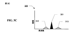
図3Aから3Cは、現在の開示のある態様によるダイナミックバンドパスフィルタの性能を示す。図3Aは、フィルタリングに先立つ合成信号300を示す。合成信号300は、対象の信号301及び2つの隣接チャネル干渉源302及び303を含む。したがって、一旦対象の信号及び隣接チャネル干渉源の強度及びロケーションが測定されれば、プロセッサは、対象の信号301に対応するそれらの周波数だけを通過させるためのダイナミックバンドパスフィルタ305を形成する。干渉源302及び303を含む残りの周波数は、バンドパスフィルタ305によって減衰させられる。減衰の結果は、図3Cで見ることができる。フィルタされた信号320では、減衰させられた干渉体312及び313は劇的に小さい振幅を有するため、フィルタされた信号320の信号対干渉比(「SIR」)を非常に改善する。
3A-3C illustrate the performance of a dynamic bandpass filter according to certain aspects of the present disclosure. FIG. 3A shows the
主題技術の別の態様によれば、ダイナミックフィルタ240はノッチフィルタ(notch filter)であることができる。そのような配置では、ダイナミックノッチフィルタ240は、干渉源のロケーションに対応するノッチを有するように調節されることができる。 According to another aspect of the subject technology, dynamic filter 240 can be a notch filter. In such an arrangement, the dynamic notch filter 240 can be adjusted to have a notch that corresponds to the location of the interference source.
ダイナミックフィルタ240は、ここでは単一のブロックレベルの要素として示されているが、ダイナミックフィルタ240がノッチフィルタである場合、それは、種々の態様によって多数のダイナミックノッチフィルタを含むことができる。例えば、信号100のような信号については、1つが低減干渉源102、1つが低減干渉源103である2つのダイナミックノッチフィルタを有することが望まれることができる。ダイナミックノッチフィルタが利用可能であるよりもより多くの隣接チャネル干渉源が存在する態様では、プロセッサ230は、限りなく最良な(best-possible)SIRを達成するために、どの隣接チャネル干渉源を減衰させるか、どれを減衰させないかを選択するように構成されることができる。あるいは、ノッチフィルタは、多数の干渉源を減衰させるのに十分に広い帯域幅を持つように構成されることができる(対象の中間信号がそれらの間で存在しない限り)。
Although the dynamic filter 240 is shown here as a single block level element, if the dynamic filter 240 is a notch filter, it can include multiple dynamic notch filters in various ways. For example, for a signal such as
主題技術の別の態様によれば、ダイナミックフィルタはローパスフィルタであることができる。そのような配置は、フィルタリングがベースバンドの変換の後に起こるような受信機装置中で利用されることができる。図4は、主題技術の1つの態様による1つのそのような受信機装置を示す。対象の信号101及び隣接チャネル干渉源102及び103がベースバンドに変換された後、測定回路430は、対象の信号101及び隣接チャネル干渉源102及び103の強度及び位置を測定し、プロセッサ440に測定に関する情報を供給する。プロセッサ440は情報を受信し、応答として、ACIに対する測定された対象の信号の相対的な強度及び位置に対応させるためにダイナミックローパスフィルタ(LPF)450を調整するための命令を生成する。
According to another aspect of the subject technology, the dynamic filter can be a low pass filter. Such an arrangement can be utilized in a receiver device where filtering occurs after baseband conversion. FIG. 4 illustrates one such receiver apparatus according to one aspect of the subject technology. After the
主題技術の1つの態様によれば、測定回路430は、対象の信号及び隣接チャネル干渉源102及び103の強度のみを測定するように構成さることができる。この態様では、プロセッサ440は、隣接チャネル干渉源102及び103に対する対象の信号の相対的な強度に対応させるダイナミックローパスフィルタ450を調節するように構成される。この点に関して、1つの検出されたACIが強ければ、ローパスフィルタ450の帯域幅は、より強いACIが存在する対象の信号の横に縮小される(reduced)ことができる。
According to one aspect of the subject technology,
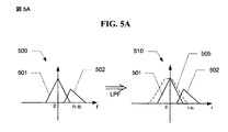
図5A及び5Bは、現在の開示のある態様によるダイナミックローパスフィルタの性能を示す。図5Aは、ローパスフィルタリングの前500及び後510の受信信号を示す。受信信号500は、対象の信号501及び隣接チャネル干渉源502の信号を含む。従って、一旦対象の信号501及びACI502の強度及びロケーションが測定されれば、プロセッサは、対象の信号501を取り出すためにダイナミックローパスフィルタ505を形成する。ローパスフィルタ505は、フィルタ505がネガティブ周波数(negative frequency)で中心に置かれるように、フィルタの右手側に強い減衰(enhanced attenuation)を備えて構成される。
5A and 5B illustrate the performance of a dynamic low pass filter according to certain aspects of the present disclosure. FIG. 5A shows the received signal before and after 510 low pass filtering. The received
図5Bは、ローパスフィルタリングの前520及び後530の受信信号を示す。受信信号520は、対象の信号521及び2つの隣接チャネル干渉源522及び523を含む。ACI522はACI523よりも強い。したがって、一旦対象の信号521及びACI522及び523のロケーションが測定されれば、プロセッサは、対象の信号521を取り出すためにダイナミックローパスフィルタ525を形成する。ローパスフィルタ525は、両側に強い減衰を備えるが、右手側ではより一層強い減衰を備えて構成される。その結果、フィルタ525は、ネガティブ周波数で中心に置かれる。
FIG. 5B shows the received signal before 520 and after 530 of the low pass filtering.
主題技術の1つの代表的な態様によれば、ACI強度測定アルゴリズムは、3dBの帯域幅BWDetでfcenter, fright 及び fleft Hzの中心に置かれたフィルタで、信号パワーレベルPcenter、ACIパワーレベルPright及びPleftを評価する(estimates)。そして、ローパスフィルタでのACIの抑制は、以下の論理にしたがって続くことができる。 According to one exemplary aspect of the subject technology, the ACI intensity measurement algorithm is a filter centered at f center , f right and f left Hz with a bandwidth BW Det of 3 dB, and a signal power level P center , Estimates the ACI power levels P right and P left . And the suppression of ACI in the low pass filter can continue according to the following logic.
もし (Pcenter/Pright <閾値、Pcenter/Pleftt >閾値)であれば、{
3dB落ちた(reduced)帯域幅のLPFを介して、より高い周波数側で受信信号を通過させる。
If (P center / P right <threshold, P center / P leftt > threshold) then {
The received signal is passed on the higher frequency side through an LPF with a reduced bandwidth of 3 dB.
}
または、もし(Pcenter/Pright >閾値、Pcenter/Pleftt <閾値)であれば、{
3dB落ちた帯域幅のLPFを介して、より低い周波数側で受信信号を通過させる。
}
Or if (P center / P right > threshold, P center / P leftt <threshold), then {
The received signal is passed through a lower frequency side through an LPF with a bandwidth dropped by 3 dB.
}
または、 (Pcenter/Pright <閾値、Pcenter/Pleftt <閾値)であれば、{
3dB落ちた帯域幅のLPFを介して、両側で受信信号を通過させる。
}
Or (P center / P right <threshold, P center / P leftt <threshold)
The received signal is passed on both sides through an LPF with a bandwidth dropped by 3 dB.
}
対象の信号及びACIの測定は特定のアルゴリズムに関して上記されたが、当業者は、対象の信号及びACIを測定するために多くの他の方法のうちの任意の1つが使用され得ることを認識するだろう。したがって、本発明の範囲は、ここで記述される対象の信号及びACIを測定するための特定の配置に限られることはなく、むしろ、当業者が知る対象の信号及びACIを測定するための任意の技術を含む。
}
While measurement of the signal of interest and ACI has been described above with respect to a particular algorithm, those skilled in the art will recognize that any one of many other methods can be used to measure the signal of interest and ACI. right. Thus, the scope of the present invention is not limited to the particular arrangement for measuring the signal and ACI of interest described herein, but rather is an arbitrary one for measuring the signal and ACI of interest known to those skilled in the art. Including technology.
図6は、主題技術の1つの態様によるACI抑制のための方法を示すフローチャートである。この方法はステップ601で始まり、ここでは信号が受信される。受信信号は、対象の信号及び起こりうる1以上の隣接チャネル干渉源を含む。ステップ602で、合成信号が随意にベースバンドに変換される。ステップ603で、対象の信号及び起こりうる1以上の隣接チャネル干渉源の強度及び位置が測定される。ステップ604で、ダイナミックフィルタのロケーションが対象の信号を取り出すために調節される。
FIG. 6 is a flowchart illustrating a method for ACI suppression according to one aspect of the subject technology. The method begins at
1つの態様によれば、測定ステップ603は、対象の信号及び起こりうる1以上の隣接チャネル干渉源の強度のみを測定することを含むことができる。そのような配置では、調節ステップ604は、測定された強度に対応する少なくとも1つのダイナミックフィルタの位置を調節することを含むことができる。
According to one aspect, the measuring
図7は、態様が実施され得るコンピュータシステム700を示すブロック図である。コンピュータシステム700は、情報を通信するためのバス702または他の通信機構、及びバス702と接続された情報を処理するためのプロセッサ704を含むことができる。コンピュータシステム700は、さらに、バス702と接続されたランダムアクセスメモリ(「RAM」)または他の動的な記憶装置のような、プロセッサ704によって実行される情報及び命令を格納するためのメモリ706を含むことができる。メモリ706は、さらに、プロセッサ704によって実行される命令の実行中に、一時変数または他の中間情報を格納するために使用されることができる。コンピュータシステム700は、磁気ディスクまたは光ディスクのような、バス702に接続され、情報及び命令を格納するためのデータ記憶装置710をさらに含むことができる。
FIG. 7 is a block diagram that illustrates a
コンピュータシステム700は、陰極線管(「CRT」)または液晶ディスプレイ(「LCD」)のような、コンピュータユーザへの情報を表示するための表示装置(図示せず)とI/Oモジュール708を介して接続されることができる。例えばキーボードまたはマウスのような入力装置は、さらに、プロセッサ704への情報及びコマンドの選択を伝えるために、I/Oモジュール708を介してコンピュータシステム700に接続されることができる。
主題技術の1つの態様によれば、ACI抑制は、メモリ706に含まれている1以上の命令の1以上のシーケンスを実行するプロセッサ704に応答してコンピュータシステム700によって実行される。そのような命令は、データ記憶装置710のような別の機械可読媒体からメモリ706に読み込まれることができる。メインメモリ706に含まれる命令のシーケンスの実行は、ここに記述される処理ステップをプロセッサ704に実行させる。多重処理配置における1以上のプロセッサも、メモリ706に含まれる命令のシーケンスを実行するために使用されることができる。代替となる態様では、ハードワイヤード回路は、種々の態様を実施するために、ソフトウェア命令の代わりとして、または、ソフトウェア命令と結合して使用されることができる。したがって、態様は、ハードウェア回路及びソフトウェアの任意の特定の組合せに制限されない。
In accordance with one aspect of the subject technology, ACI suppression is performed by
ここで使用される用語「機械可読媒体」は、実行用のプロセッサ704に命令を供給することに関係する任意の媒体を指す。そのような媒体は、限定されないが、不揮発性媒体、揮発性媒体及び伝送媒体を含む多くの形式をとることができる。不揮発性媒体は、例えば、データ記憶装置710のような光学または磁気ディスクを含む。揮発性媒体は、メモリ706のような動的なメモリを含む。伝送媒体は、バス702を備えるワイヤを含む同軸ケーブル、銅線及び光ファイバ(fiber optics)を含む。伝送媒体は、さらに、無線周波数及び赤外線データの通信中に生成されるもののような音響波または光波の形式をとることができる。機械可読媒体の共通の形式は、例えば、コンピュータが読み出すことができるフロッピー(登録商標)ディスク、フレキシブルディスク、ハードディスク、磁気テープ、任意の他の磁気媒体、CD−ROM、DVD、任意の他の光学媒体、パンチカード、紙テープ、穴のパターンを備える任意の物理媒体、RAM、PROM、EPROM、FLASH EPROM、任意の他のメモリチップまたはカートリッジ、搬送波または任意の他の媒体を含む。
The term “machine-readable medium” as used herein refers to any medium that participates in providing instructions to
当業者は、種々の実例となるブロック、モジュール、エレメント(elements)、コンポーネント(components)、方法、及びアルゴリズムが電子ハードウェア、コンピュータソフトウェアまたは両方の組合せとして実施されることができることを認識するだろう。さらに、これらは、記述されるものとは異なって分離されることができる。ハードウェアとソフトウェアのこの互換性を示すために、種々の実例となるブロック、モジュール、エレメント、コンポーネント、方法およびアルゴリズムは、それらの機能性の観点から一般に上記説明されてきた。そのような機能性がハードウェアまたはソフトウェアとして実施されるかどうかは、全体のシステムに課された特定のアプリケーション及び設計制約に依存する。当業者は、各特定のアプリケーションの方法を変える際に記述された機能性を実施することができる。 Those skilled in the art will recognize that the various illustrative blocks, modules, elements, components, methods, and algorithms can be implemented as electronic hardware, computer software, or a combination of both. . Furthermore, they can be separated differently than described. To illustrate this interchangeability of hardware and software, various illustrative blocks, modules, elements, components, methods, and algorithms have been generally described above in terms of their functionality. Whether such functionality is implemented as hardware or software depends upon the particular application and design constraints imposed on the overall system. One skilled in the art can implement the described functionality in changing the way for each particular application.
開示されたプロセスのステップまたはブロックの特定の順番または階層が代表的なアプローチの実例であることは、理解される。設計選択に基づいて、プロセスのステップまたはブロックの特定の順番または階層が再編成され得ることは理解される。付随する方法は、見本となる順番の種々のステップの現在のエレメントを要求し、特定の順番または階層に限定されることは意図されていない。 It is understood that the specific order or hierarchy of disclosed process steps or blocks is illustrative of a representative approach. It will be understood that a particular order or hierarchy of process steps or blocks may be rearranged based on design choices. The accompanying method requires the current elements of the various steps in the sample order and is not intended to be limited to a specific order or hierarchy.
先の記述は、いかなる当業者もここに記述された種々の態様を実行することを可能にするために提供される。これらの態様に対する種々の改良は、当業者に容易に明白になるだろう。ここで定義された一般的な法則は、他の態様にも適用されることができる。したがって、請求項は、ここに示された態様に限定されるように意図されないが、言語上の請求と一致する十分な範囲が与えられることになり、単数のエレメントへの言及は、特にそのように述べられていない限り、「1及び1のみ」を意味するようには意図されず、むしろ、「1以上」である。特に何か述べられていない限り、用語「いくらか」は1以上を指す。男性的な(例えば彼)代名詞は、女性、中性の性別(例えば、彼女、それ)を含み、逆も同じである。当業者に知られた、または後に知られることになるこの開示を通じて記載された種々の態様の要素への全ての構成上の及び機能上の等価物は、参照によって明らかにここに組込まれ、請求項によって含まれるように意図される。さらに、ここに示されたいかなるものも、そのような開示が請求項で明示的に示されるかどうかにかかわらず公に捧げられるようには意図されない。請求項の要素は、その要素が明確に句「ための手段」を使用して示されていない、または、方法の請求項の場合には、その要素が句「するためのステップ」を使用して示されていない限り、35U.S.C.§112の第6段落の条件の下で解釈されるように意図されない。 The previous description is provided to enable any person skilled in the art to perform the various aspects described herein. Various improvements to these embodiments will be readily apparent to those skilled in the art. The general rules defined here can be applied to other aspects. Thus, the claims are not intended to be limited to the embodiments shown herein, but will be given sufficient scope consistent with the language claims, and references to singular elements are particularly so. Is not intended to mean “1 and 1 only”, but rather “1 or more”. Unless stated otherwise, the term “some” refers to one or more. Masculine (eg, he) pronouns include female, neutral gender (eg, her, it), and vice versa. All structural and functional equivalents to the elements of the various embodiments described throughout this disclosure that will be known or later known to those skilled in the art are hereby expressly incorporated by reference and are hereby claimed. It is intended to be included by the section. Moreover, nothing presented herein is intended to be dedicated to the public regardless of whether such disclosure is explicitly set forth in the claims. An element of a claim is not explicitly indicated using the phrase “means for” or, in the case of a method claim, the element uses the phrase “step to do”. Unless otherwise indicated, 35U. S. C. It is not intended to be interpreted under the conditions of the sixth paragraph of §112.
Claims (40)
前記対象の信号及び前記1以上の隣接チャネル干渉源の強度及び/またはロケーションを測定することと、
前記対象の信号を取り出すために少なくとも1つのダイナミックフィルタのロケーションを調節すること、
のステップを備えるACI抑制のための方法。 Receiving a composite signal including the signal of interest and one or more adjacent channel interference sources;
Measuring the intensity and / or location of the signal of interest and the one or more adjacent channel interferers;
Adjusting the location of at least one dynamic filter to extract the signal of interest;
A method for ACI suppression comprising the steps of:
前記対象の信号及び起こりうる前記1以上の隣接チャネル干渉源の前記測定に関する情報をプロセッサで受信することと、
前記受信情報に応じて、前記少なくとも1つのダイナミックフィルタの前記ロケーションを調整することに関する命令を前記プロセッサで生成すること、
を含む、請求項1の方法。 Adjusting the location of the at least one dynamic filter comprises:
Receiving at the processor information about the signal of interest and possible measurements of the one or more adjacent channel interference sources;
Generating instructions on the processor to adjust the location of the at least one dynamic filter in response to the received information;
The method of claim 1 comprising:
前記対象の信号及び前記1以上の隣接チャネル干渉源の強度及び/またはロケーションを測定するように構成された干渉測定回路と、
前記対象の信号を取り出すように構成された少なくとも1つのダイナミックフィルタと、
前記対象の信号を取り出すために前記少なくとも1つのダイナミックフィルタのロケーションを調節するように構成されたプロセッサと、
を備える受信装置。 An antenna configured to receive a combined signal including the signal of interest and one or more adjacent channel interferers;
An interference measurement circuit configured to measure the intensity and / or location of the signal of interest and the one or more adjacent channel interferers;
At least one dynamic filter configured to extract the signal of interest;
A processor configured to adjust a location of the at least one dynamic filter to retrieve the signal of interest;
A receiving device.
前記対象の信号及び前記1以上の隣接チャネル干渉源の強度及び/またはロケーションを測定することと、
前記対象の信号を取り出すために少なくとも1つのダイナミックフィルタのロケーションを調節すること、
に関するコードを備えるACIを抑制するための命令を備える機械可読媒体。 Receiving a composite signal including the signal of interest and one or more adjacent channel interference sources;
Measuring the intensity and / or location of the signal of interest and the one or more adjacent channel interferers;
Adjusting the location of at least one dynamic filter to extract the signal of interest;
A machine-readable medium comprising instructions for suppressing ACI comprising code relating to
前記1以上の隣接チャネル干渉源の前記強度に関連のある前記対象の信号の前記強度に対応させるために少なくとも1つのダイナミックフィルタのロケーションを調整するように構成されたACIを抑制するためのプロセッサ。 Measure the strength of the signal of interest and the strength of one or more possible adjacent channel interferers;
A processor for suppressing ACI configured to adjust a location of at least one dynamic filter to correspond to the intensity of the signal of interest related to the intensity of the one or more adjacent channel interferers.
前記1以上の隣接チャネル干渉源に関するロケーションを測定し、
前記1以上の隣接チャネル干渉源の前記強度及び前記ロケーションに関連のある前記対象の信号の前記強度及び前記ロケーションに対応させるために前記少なくとも1つのダイナミックフィルタの前記ロケーションを調整するようにさらに構成されている請求項39のプロセッサ。 The processor is
Measuring a location with respect to the one or more adjacent channel interferers;
Further configured to adjust the location of the at least one dynamic filter to correspond to the strength and the location of the signal of interest associated with the strength and the location of the one or more adjacent channel interferers. 40. The processor of claim 39.
Applications Claiming Priority (3)
| Application Number | Priority Date | Filing Date | Title |
|---|---|---|---|
| US12/165,667 US20100002815A1 (en) | 2008-07-01 | 2008-07-01 | Dynamic filtering for adjacent channel interference suppression |
| US12/165,667 | 2008-07-01 | ||
| PCT/US2009/049331 WO2010002946A1 (en) | 2008-07-01 | 2009-06-30 | Dynamic filtering for adjacent channel interference suppression |
Publications (2)
| Publication Number | Publication Date |
|---|---|
| JP2011527160A true JP2011527160A (en) | 2011-10-20 |
| JP2011527160A5 JP2011527160A5 (en) | 2011-12-01 |
Family
ID=41165577
Family Applications (1)
| Application Number | Title | Priority Date | Filing Date |
|---|---|---|---|
| JP2011516839A Pending JP2011527160A (en) | 2008-07-01 | 2009-06-30 | Dynamic filtering for adjacent channel interference suppression |
Country Status (10)
| Country | Link |
|---|---|
| US (1) | US20100002815A1 (en) |
| EP (1) | EP2313981A1 (en) |
| JP (1) | JP2011527160A (en) |
| KR (1) | KR101230355B1 (en) |
| CN (1) | CN102077473A (en) |
| BR (1) | BRPI0914113A2 (en) |
| CA (1) | CA2728305C (en) |
| RU (1) | RU2466498C2 (en) |
| TW (1) | TWI436600B (en) |
| WO (1) | WO2010002946A1 (en) |
Families Citing this family (7)
| Publication number | Priority date | Publication date | Assignee | Title |
|---|---|---|---|---|
| US8116713B2 (en) * | 2008-11-26 | 2012-02-14 | Visteon Global Technologies, Inc. | Automatic bandwidth control with high-deviation detection |
| KR101310721B1 (en) * | 2009-08-11 | 2013-09-24 | 퀄컴 인코포레이티드 | Adaptive transmission (tx)/reception (rx) pulse shaping filter for femtocell base stations and mobile stations within a network |
| US9143182B2 (en) * | 2012-04-24 | 2015-09-22 | Lockheed Martin Corporation | Adaptive cosite arbitration system |
| CN103685095B (en) * | 2013-12-18 | 2017-01-04 | 北京创毅视讯科技有限公司 | A kind of method and apparatus realizing monkey chatter suppression |
| CN104753545B (en) * | 2013-12-30 | 2019-02-15 | 中兴通讯股份有限公司 | A kind of IF process method, apparatus and base station |
| US9350483B2 (en) * | 2014-01-15 | 2016-05-24 | Qualcomm Incorporated | Mitigate adjacent channel interference and non-Wi-Fi interference |
| CN104902054B (en) * | 2015-06-24 | 2018-07-06 | 小米科技有限责任公司 | Filter out the method and device of the interference frequency point of mobile terminal |
Citations (3)
| Publication number | Priority date | Publication date | Assignee | Title |
|---|---|---|---|---|
| JPH09266452A (en) * | 1996-03-27 | 1997-10-07 | Matsushita Electric Ind Co Ltd | Reception device |
| JP2005347810A (en) * | 2004-05-31 | 2005-12-15 | Pioneer Electronic Corp | Adjacent disturbance detection apparatus, adjacent disturbance elimination apparatus, and receiver |
| JP2006166367A (en) * | 2004-12-10 | 2006-06-22 | Pioneer Electronic Corp | High frequency receiver and method of reducing adjacent interference wave |
Family Cites Families (13)
| Publication number | Priority date | Publication date | Assignee | Title |
|---|---|---|---|---|
| DE3416493A1 (en) * | 1984-05-04 | 1985-11-07 | Standard Elektrik Lorenz Ag, 7000 Stuttgart | OPTICAL RECEIVING DEVICE |
| US5151939A (en) * | 1990-03-21 | 1992-09-29 | Delco Electronics Corporation | Adaptive audio processor for am stereo signals |
| JP2874457B2 (en) * | 1992-05-29 | 1999-03-24 | 日本電気株式会社 | Demodulator |
| DE4319457C2 (en) * | 1993-06-11 | 1997-09-04 | Blaupunkt Werke Gmbh | Circuit arrangement for adjacent channel detection and suppression in an FM radio receiver |
| US6026129A (en) * | 1996-03-27 | 2000-02-15 | Matsushita Electric Industrial Co., Ltd. | Radio receiving apparatus for receiving communication signals of different bandwidths |
| EP1419583B1 (en) * | 2001-08-23 | 2005-02-16 | Siemens Aktiengesellschaft | Adaptive filtering method and filter for filtering a radio signal in a mobile radio-communication system |
| US6901243B2 (en) * | 2001-11-08 | 2005-05-31 | Qualcomm, Incorporated | Method and apparatus for mitigating adjacent channel interference in a wireless communication system |
| RU2205422C1 (en) * | 2002-04-19 | 2003-05-27 | Открытое акционерное общество "Научно-производственное объединение "Алмаз" им. акад. А.А.Расплетина" | Multichannel correlation-filtration receiving facility |
| JP3465707B1 (en) * | 2002-05-27 | 2003-11-10 | 日本電気株式会社 | Carrier sense multiple access receiver and its interference suppression method |
| US7039093B2 (en) * | 2002-06-14 | 2006-05-02 | Siemens Communications, Inc. | Arrangement for adaptive baseband filter selection |
| JP2004040367A (en) * | 2002-07-02 | 2004-02-05 | Pioneer Electronic Corp | Receiver with function for removing adjacent interfering wave |
| FR2871966B1 (en) * | 2004-06-17 | 2006-09-22 | Nortel Networks Ltd | METHOD AND DEVICE FOR PROCESSING SIGNAL IN A RADIO COMMUNICATION RECEIVER |
| RU2289202C2 (en) * | 2004-11-23 | 2006-12-10 | Зао "Элвиис" | Digital multi-channel reprogrammable reception path |
-
2008
- 2008-07-01 US US12/165,667 patent/US20100002815A1/en not_active Abandoned
-
2009
- 2009-06-30 BR BRPI0914113A patent/BRPI0914113A2/en not_active IP Right Cessation
- 2009-06-30 RU RU2011103461/08A patent/RU2466498C2/en not_active IP Right Cessation
- 2009-06-30 WO PCT/US2009/049331 patent/WO2010002946A1/en active Application Filing
- 2009-06-30 CN CN200980124970XA patent/CN102077473A/en active Pending
- 2009-06-30 EP EP09774396A patent/EP2313981A1/en not_active Withdrawn
- 2009-06-30 CA CA2728305A patent/CA2728305C/en not_active Expired - Fee Related
- 2009-06-30 JP JP2011516839A patent/JP2011527160A/en active Pending
- 2009-06-30 KR KR1020117002610A patent/KR101230355B1/en not_active IP Right Cessation
- 2009-07-01 TW TW098122284A patent/TWI436600B/en not_active IP Right Cessation
Patent Citations (3)
| Publication number | Priority date | Publication date | Assignee | Title |
|---|---|---|---|---|
| JPH09266452A (en) * | 1996-03-27 | 1997-10-07 | Matsushita Electric Ind Co Ltd | Reception device |
| JP2005347810A (en) * | 2004-05-31 | 2005-12-15 | Pioneer Electronic Corp | Adjacent disturbance detection apparatus, adjacent disturbance elimination apparatus, and receiver |
| JP2006166367A (en) * | 2004-12-10 | 2006-06-22 | Pioneer Electronic Corp | High frequency receiver and method of reducing adjacent interference wave |
Also Published As
| Publication number | Publication date |
|---|---|
| TW201008142A (en) | 2010-02-16 |
| KR20110026509A (en) | 2011-03-15 |
| RU2466498C2 (en) | 2012-11-10 |
| CA2728305A1 (en) | 2010-01-07 |
| CN102077473A (en) | 2011-05-25 |
| RU2011103461A (en) | 2012-08-10 |
| KR101230355B1 (en) | 2013-02-06 |
| CA2728305C (en) | 2014-04-08 |
| BRPI0914113A2 (en) | 2015-10-20 |
| TWI436600B (en) | 2014-05-01 |
| US20100002815A1 (en) | 2010-01-07 |
| WO2010002946A1 (en) | 2010-01-07 |
| EP2313981A1 (en) | 2011-04-27 |
Similar Documents
| Publication | Publication Date | Title |
|---|---|---|
| JP2011527160A (en) | Dynamic filtering for adjacent channel interference suppression | |
| JP6557786B2 (en) | Echo delay tracking method, apparatus and computer storage medium | |
| CN103346845B (en) | Based on blind frequency spectrum sensing method and the device of fast Fourier transform | |
| US20200292572A1 (en) | Wireless motion detection using multiband filters | |
| CN110706693B (en) | Method and device for determining voice endpoint, storage medium and electronic device | |
| CN106199532B (en) | Based on mixing Fourier-wavelet analysis Gpr Signal noise-reduction method | |
| US8750804B2 (en) | Applying spurious interference rejection to detect incumbent users of television channels | |
| US9877118B2 (en) | Method for frequency-dependent noise suppression of an input signal | |
| CN112802486B (en) | Noise suppression method and device and electronic equipment | |
| CN112711045B (en) | Method and device for processing interference in navigation signal | |
| CN112151051B (en) | Audio data processing method and device and storage medium | |
| CN113205824B (en) | Sound signal processing method, device, storage medium, chip and related equipment | |
| CN114302286A (en) | Method, device and equipment for reducing noise of call voice and storage medium | |
| Mukherjee et al. | New method for enhanced efficiency in detection of gravitational waves from supernovae using coherent network of detectors | |
| CN116705045B (en) | Echo cancellation method, apparatus, computer device and storage medium | |
| WO2015195482A1 (en) | Multi-aural mmse analysis techniques for clarifying audio signals | |
| JP2017129741A (en) | Noise reduction device and noise reduction method | |
| CN115842568A (en) | Interference-free communication method and narrow-band wireless communication chip | |
| US20230352039A1 (en) | Audio signal processing method, electronic device and storage medium | |
| CN109150343B (en) | Collision signal detection method and device, communication equipment and storage medium | |
| CN116013337B (en) | Audio signal processing method, training method, device, equipment and medium for model | |
| CN113573205B (en) | Signal processing method, apparatus and computer storage medium | |
| CN115209135B (en) | Electromagnetic leakage video detection and restoration system | |
| CN117711434A (en) | Audio processing method and device, electronic equipment and computer readable storage medium | |
| CN116781188A (en) | Spread spectrum signal detection method, medium and device based on channelized multi-scale time-frequency accumulation |
Legal Events
| Date | Code | Title | Description |
|---|---|---|---|
| A521 | Written amendment |
Free format text: JAPANESE INTERMEDIATE CODE: A523 Effective date: 20110929 |
|
| A977 | Report on retrieval |
Free format text: JAPANESE INTERMEDIATE CODE: A971007 Effective date: 20120706 |
|
| A131 | Notification of reasons for refusal |
Free format text: JAPANESE INTERMEDIATE CODE: A131 Effective date: 20120710 |
|
| A601 | Written request for extension of time |
Free format text: JAPANESE INTERMEDIATE CODE: A601 Effective date: 20121010 |
|
| A602 | Written permission of extension of time |
Free format text: JAPANESE INTERMEDIATE CODE: A602 Effective date: 20121017 |
|
| A521 | Written amendment |
Free format text: JAPANESE INTERMEDIATE CODE: A523 Effective date: 20121102 |
|
| A02 | Decision of refusal |
Free format text: JAPANESE INTERMEDIATE CODE: A02 Effective date: 20130528 |