JP2011524209A - Method and apparatus for joint distraction - Google Patents
Method and apparatus for joint distraction Download PDFInfo
- Publication number
- JP2011524209A JP2011524209A JP2011513735A JP2011513735A JP2011524209A JP 2011524209 A JP2011524209 A JP 2011524209A JP 2011513735 A JP2011513735 A JP 2011513735A JP 2011513735 A JP2011513735 A JP 2011513735A JP 2011524209 A JP2011524209 A JP 2011524209A
- Authority
- JP
- Japan
- Prior art keywords
- joint
- balloon
- expandable member
- expandable
- acetabulum
- Prior art date
- Legal status (The legal status is an assumption and is not a legal conclusion. Google has not performed a legal analysis and makes no representation as to the accuracy of the status listed.)
- Pending
Links
- UAEPNZWRGJTJPN-UHFFFAOYSA-N CC1CCCCC1 Chemical compound CC1CCCCC1 UAEPNZWRGJTJPN-UHFFFAOYSA-N 0.000 description 1
Images


Classifications
-
- A—HUMAN NECESSITIES
- A61—MEDICAL OR VETERINARY SCIENCE; HYGIENE
- A61B—DIAGNOSIS; SURGERY; IDENTIFICATION
- A61B17/00—Surgical instruments, devices or methods, e.g. tourniquets
- A61B17/02—Surgical instruments, devices or methods, e.g. tourniquets for holding wounds open; Tractors
- A61B17/025—Joint distractors
-
- A—HUMAN NECESSITIES
- A61—MEDICAL OR VETERINARY SCIENCE; HYGIENE
- A61B—DIAGNOSIS; SURGERY; IDENTIFICATION
- A61B1/00—Instruments for performing medical examinations of the interior of cavities or tubes of the body by visual or photographical inspection, e.g. endoscopes; Illuminating arrangements therefor
- A61B1/313—Instruments for performing medical examinations of the interior of cavities or tubes of the body by visual or photographical inspection, e.g. endoscopes; Illuminating arrangements therefor for introducing through surgical openings, e.g. laparoscopes
- A61B1/317—Instruments for performing medical examinations of the interior of cavities or tubes of the body by visual or photographical inspection, e.g. endoscopes; Illuminating arrangements therefor for introducing through surgical openings, e.g. laparoscopes for bones or joints, e.g. osteoscopes, arthroscopes
-
- A—HUMAN NECESSITIES
- A61—MEDICAL OR VETERINARY SCIENCE; HYGIENE
- A61B—DIAGNOSIS; SURGERY; IDENTIFICATION
- A61B17/00—Surgical instruments, devices or methods, e.g. tourniquets
- A61B17/02—Surgical instruments, devices or methods, e.g. tourniquets for holding wounds open; Tractors
- A61B17/0218—Surgical instruments, devices or methods, e.g. tourniquets for holding wounds open; Tractors for minimally invasive surgery
-
- A—HUMAN NECESSITIES
- A61—MEDICAL OR VETERINARY SCIENCE; HYGIENE
- A61B—DIAGNOSIS; SURGERY; IDENTIFICATION
- A61B17/00—Surgical instruments, devices or methods, e.g. tourniquets
- A61B17/34—Trocars; Puncturing needles
- A61B17/3417—Details of tips or shafts, e.g. grooves, expandable, bendable; Multiple coaxial sliding cannulas, e.g. for dilating
- A61B17/3421—Cannulas
-
- A—HUMAN NECESSITIES
- A61—MEDICAL OR VETERINARY SCIENCE; HYGIENE
- A61F—FILTERS IMPLANTABLE INTO BLOOD VESSELS; PROSTHESES; DEVICES PROVIDING PATENCY TO, OR PREVENTING COLLAPSING OF, TUBULAR STRUCTURES OF THE BODY, e.g. STENTS; ORTHOPAEDIC, NURSING OR CONTRACEPTIVE DEVICES; FOMENTATION; TREATMENT OR PROTECTION OF EYES OR EARS; BANDAGES, DRESSINGS OR ABSORBENT PADS; FIRST-AID KITS
- A61F5/00—Orthopaedic methods or devices for non-surgical treatment of bones or joints; Nursing devices; Anti-rape devices
- A61F5/01—Orthopaedic devices, e.g. splints, casts or braces
- A61F5/0193—Apparatus specially adapted for treating hip dislocation; Abduction splints
-
- A—HUMAN NECESSITIES
- A61—MEDICAL OR VETERINARY SCIENCE; HYGIENE
- A61M—DEVICES FOR INTRODUCING MEDIA INTO, OR ONTO, THE BODY; DEVICES FOR TRANSDUCING BODY MEDIA OR FOR TAKING MEDIA FROM THE BODY; DEVICES FOR PRODUCING OR ENDING SLEEP OR STUPOR
- A61M25/00—Catheters; Hollow probes
- A61M25/0067—Catheters; Hollow probes characterised by the distal end, e.g. tips
- A61M25/008—Strength or flexibility characteristics of the catheter tip
-
- A—HUMAN NECESSITIES
- A61—MEDICAL OR VETERINARY SCIENCE; HYGIENE
- A61M—DEVICES FOR INTRODUCING MEDIA INTO, OR ONTO, THE BODY; DEVICES FOR TRANSDUCING BODY MEDIA OR FOR TAKING MEDIA FROM THE BODY; DEVICES FOR PRODUCING OR ENDING SLEEP OR STUPOR
- A61M25/00—Catheters; Hollow probes
- A61M25/10—Balloon catheters
- A61M25/1002—Balloon catheters characterised by balloon shape
-
- A—HUMAN NECESSITIES
- A61—MEDICAL OR VETERINARY SCIENCE; HYGIENE
- A61M—DEVICES FOR INTRODUCING MEDIA INTO, OR ONTO, THE BODY; DEVICES FOR TRANSDUCING BODY MEDIA OR FOR TAKING MEDIA FROM THE BODY; DEVICES FOR PRODUCING OR ENDING SLEEP OR STUPOR
- A61M25/00—Catheters; Hollow probes
- A61M25/10—Balloon catheters
- A61M25/1027—Making of balloon catheters
-
- A—HUMAN NECESSITIES
- A61—MEDICAL OR VETERINARY SCIENCE; HYGIENE
- A61B—DIAGNOSIS; SURGERY; IDENTIFICATION
- A61B17/00—Surgical instruments, devices or methods, e.g. tourniquets
- A61B17/02—Surgical instruments, devices or methods, e.g. tourniquets for holding wounds open; Tractors
-
- A—HUMAN NECESSITIES
- A61—MEDICAL OR VETERINARY SCIENCE; HYGIENE
- A61B—DIAGNOSIS; SURGERY; IDENTIFICATION
- A61B17/00—Surgical instruments, devices or methods, e.g. tourniquets
- A61B2017/00017—Electrical control of surgical instruments
- A61B2017/00115—Electrical control of surgical instruments with audible or visual output
-
- A—HUMAN NECESSITIES
- A61—MEDICAL OR VETERINARY SCIENCE; HYGIENE
- A61B—DIAGNOSIS; SURGERY; IDENTIFICATION
- A61B17/00—Surgical instruments, devices or methods, e.g. tourniquets
- A61B2017/00535—Surgical instruments, devices or methods, e.g. tourniquets pneumatically or hydraulically operated
- A61B2017/00557—Surgical instruments, devices or methods, e.g. tourniquets pneumatically or hydraulically operated inflatable
-
- A—HUMAN NECESSITIES
- A61—MEDICAL OR VETERINARY SCIENCE; HYGIENE
- A61B—DIAGNOSIS; SURGERY; IDENTIFICATION
- A61B17/00—Surgical instruments, devices or methods, e.g. tourniquets
- A61B17/02—Surgical instruments, devices or methods, e.g. tourniquets for holding wounds open; Tractors
- A61B2017/0212—Cushions or pads, without holding arms, as tissue retainers, e.g. for retracting viscera
-
- A—HUMAN NECESSITIES
- A61—MEDICAL OR VETERINARY SCIENCE; HYGIENE
- A61B—DIAGNOSIS; SURGERY; IDENTIFICATION
- A61B17/00—Surgical instruments, devices or methods, e.g. tourniquets
- A61B17/02—Surgical instruments, devices or methods, e.g. tourniquets for holding wounds open; Tractors
- A61B17/0218—Surgical instruments, devices or methods, e.g. tourniquets for holding wounds open; Tractors for minimally invasive surgery
- A61B2017/0225—Surgical instruments, devices or methods, e.g. tourniquets for holding wounds open; Tractors for minimally invasive surgery flexible, e.g. fabrics, meshes, or membranes
-
- A—HUMAN NECESSITIES
- A61—MEDICAL OR VETERINARY SCIENCE; HYGIENE
- A61B—DIAGNOSIS; SURGERY; IDENTIFICATION
- A61B17/00—Surgical instruments, devices or methods, e.g. tourniquets
- A61B17/02—Surgical instruments, devices or methods, e.g. tourniquets for holding wounds open; Tractors
- A61B17/025—Joint distractors
- A61B2017/0275—Joint distractors for the hip
-
- A—HUMAN NECESSITIES
- A61—MEDICAL OR VETERINARY SCIENCE; HYGIENE
- A61B—DIAGNOSIS; SURGERY; IDENTIFICATION
- A61B17/00—Surgical instruments, devices or methods, e.g. tourniquets
- A61B17/34—Trocars; Puncturing needles
- A61B2017/348—Means for supporting the trocar against the body or retaining the trocar inside the body
- A61B2017/3482—Means for supporting the trocar against the body or retaining the trocar inside the body inside
- A61B2017/3484—Anchoring means, e.g. spreading-out umbrella-like structure
- A61B2017/3488—Fixation to inner organ or inner body tissue
-
- A—HUMAN NECESSITIES
- A61—MEDICAL OR VETERINARY SCIENCE; HYGIENE
- A61M—DEVICES FOR INTRODUCING MEDIA INTO, OR ONTO, THE BODY; DEVICES FOR TRANSDUCING BODY MEDIA OR FOR TAKING MEDIA FROM THE BODY; DEVICES FOR PRODUCING OR ENDING SLEEP OR STUPOR
- A61M25/00—Catheters; Hollow probes
- A61M25/0043—Catheters; Hollow probes characterised by structural features
- A61M2025/0063—Catheters; Hollow probes characterised by structural features having means, e.g. stylets, mandrils, rods or wires to reinforce or adjust temporarily the stiffness, column strength or pushability of catheters which are already inserted into the human body
-
- A—HUMAN NECESSITIES
- A61—MEDICAL OR VETERINARY SCIENCE; HYGIENE
- A61M—DEVICES FOR INTRODUCING MEDIA INTO, OR ONTO, THE BODY; DEVICES FOR TRANSDUCING BODY MEDIA OR FOR TAKING MEDIA FROM THE BODY; DEVICES FOR PRODUCING OR ENDING SLEEP OR STUPOR
- A61M25/00—Catheters; Hollow probes
- A61M25/0067—Catheters; Hollow probes characterised by the distal end, e.g. tips
- A61M25/008—Strength or flexibility characteristics of the catheter tip
- A61M2025/0081—Soft tip
-
- A—HUMAN NECESSITIES
- A61—MEDICAL OR VETERINARY SCIENCE; HYGIENE
- A61M—DEVICES FOR INTRODUCING MEDIA INTO, OR ONTO, THE BODY; DEVICES FOR TRANSDUCING BODY MEDIA OR FOR TAKING MEDIA FROM THE BODY; DEVICES FOR PRODUCING OR ENDING SLEEP OR STUPOR
- A61M25/00—Catheters; Hollow probes
- A61M25/01—Introducing, guiding, advancing, emplacing or holding catheters
- A61M25/0105—Steering means as part of the catheter or advancing means; Markers for positioning
- A61M25/0133—Tip steering devices
- A61M2025/0163—Looped catheters
-
- A—HUMAN NECESSITIES
- A61—MEDICAL OR VETERINARY SCIENCE; HYGIENE
- A61M—DEVICES FOR INTRODUCING MEDIA INTO, OR ONTO, THE BODY; DEVICES FOR TRANSDUCING BODY MEDIA OR FOR TAKING MEDIA FROM THE BODY; DEVICES FOR PRODUCING OR ENDING SLEEP OR STUPOR
- A61M25/00—Catheters; Hollow probes
- A61M25/10—Balloon catheters
- A61M2025/1043—Balloon catheters with special features or adapted for special applications
- A61M2025/1068—Balloon catheters with special features or adapted for special applications having means for varying the length or diameter of the deployed balloon, this variations could be caused by excess pressure
-
- A—HUMAN NECESSITIES
- A61—MEDICAL OR VETERINARY SCIENCE; HYGIENE
- A61M—DEVICES FOR INTRODUCING MEDIA INTO, OR ONTO, THE BODY; DEVICES FOR TRANSDUCING BODY MEDIA OR FOR TAKING MEDIA FROM THE BODY; DEVICES FOR PRODUCING OR ENDING SLEEP OR STUPOR
- A61M25/00—Catheters; Hollow probes
- A61M25/10—Balloon catheters
- A61M2025/1043—Balloon catheters with special features or adapted for special applications
- A61M2025/1072—Balloon catheters with special features or adapted for special applications having balloons with two or more compartments
-
- A—HUMAN NECESSITIES
- A61—MEDICAL OR VETERINARY SCIENCE; HYGIENE
- A61M—DEVICES FOR INTRODUCING MEDIA INTO, OR ONTO, THE BODY; DEVICES FOR TRANSDUCING BODY MEDIA OR FOR TAKING MEDIA FROM THE BODY; DEVICES FOR PRODUCING OR ENDING SLEEP OR STUPOR
- A61M25/00—Catheters; Hollow probes
- A61M25/10—Balloon catheters
- A61M2025/1043—Balloon catheters with special features or adapted for special applications
- A61M2025/1081—Balloon catheters with special features or adapted for special applications having sheaths or the like for covering the balloon but not forming a permanent part of the balloon, e.g. retractable, dissolvable or tearable sheaths
-
- A—HUMAN NECESSITIES
- A61—MEDICAL OR VETERINARY SCIENCE; HYGIENE
- A61M—DEVICES FOR INTRODUCING MEDIA INTO, OR ONTO, THE BODY; DEVICES FOR TRANSDUCING BODY MEDIA OR FOR TAKING MEDIA FROM THE BODY; DEVICES FOR PRODUCING OR ENDING SLEEP OR STUPOR
- A61M25/00—Catheters; Hollow probes
- A61M25/10—Balloon catheters
- A61M2025/1043—Balloon catheters with special features or adapted for special applications
- A61M2025/1086—Balloon catheters with special features or adapted for special applications having a special balloon surface topography, e.g. pores, protuberances, spikes or grooves
-
- A—HUMAN NECESSITIES
- A61—MEDICAL OR VETERINARY SCIENCE; HYGIENE
- A61M—DEVICES FOR INTRODUCING MEDIA INTO, OR ONTO, THE BODY; DEVICES FOR TRANSDUCING BODY MEDIA OR FOR TAKING MEDIA FROM THE BODY; DEVICES FOR PRODUCING OR ENDING SLEEP OR STUPOR
- A61M25/00—Catheters; Hollow probes
- A61M25/10—Balloon catheters
- A61M2025/1043—Balloon catheters with special features or adapted for special applications
- A61M2025/1088—Balloon catheters with special features or adapted for special applications having special surface characteristics depending on material properties or added substances, e.g. for reducing friction
-
- A—HUMAN NECESSITIES
- A61—MEDICAL OR VETERINARY SCIENCE; HYGIENE
- A61M—DEVICES FOR INTRODUCING MEDIA INTO, OR ONTO, THE BODY; DEVICES FOR TRANSDUCING BODY MEDIA OR FOR TAKING MEDIA FROM THE BODY; DEVICES FOR PRODUCING OR ENDING SLEEP OR STUPOR
- A61M25/00—Catheters; Hollow probes
- A61M25/0067—Catheters; Hollow probes characterised by the distal end, e.g. tips
- A61M25/0068—Static characteristics of the catheter tip, e.g. shape, atraumatic tip, curved tip or tip structure
-
- A—HUMAN NECESSITIES
- A61—MEDICAL OR VETERINARY SCIENCE; HYGIENE
- A61M—DEVICES FOR INTRODUCING MEDIA INTO, OR ONTO, THE BODY; DEVICES FOR TRANSDUCING BODY MEDIA OR FOR TAKING MEDIA FROM THE BODY; DEVICES FOR PRODUCING OR ENDING SLEEP OR STUPOR
- A61M25/00—Catheters; Hollow probes
- A61M25/01—Introducing, guiding, advancing, emplacing or holding catheters
- A61M25/0102—Insertion or introduction using an inner stiffening member, e.g. stylet or push-rod
-
- A—HUMAN NECESSITIES
- A61—MEDICAL OR VETERINARY SCIENCE; HYGIENE
- A61M—DEVICES FOR INTRODUCING MEDIA INTO, OR ONTO, THE BODY; DEVICES FOR TRANSDUCING BODY MEDIA OR FOR TAKING MEDIA FROM THE BODY; DEVICES FOR PRODUCING OR ENDING SLEEP OR STUPOR
- A61M25/00—Catheters; Hollow probes
- A61M25/01—Introducing, guiding, advancing, emplacing or holding catheters
- A61M25/0105—Steering means as part of the catheter or advancing means; Markers for positioning
- A61M25/0133—Tip steering devices
- A61M25/0147—Tip steering devices with movable mechanical means, e.g. pull wires
Abstract
互いに対向する関節表面を有する患者の関節を治療する方法には、近位端、遠位端、および遠位端の近傍の膨張可能部材を有する細長い部材を提供するステップが含まれている。膨張可能部材は、関節表面と関節表面の間の関節の中に配置され、膨張してこれらの関節表面を伸延した位置に互いに分離する。関節は、関節が伸延するよう、また、屈曲状態になるよう、伸延した位置に位置している間に操作される。次に、関節を屈曲した位置および伸延した位置に維持した状態でその関節に対する診断または治療手順が実施される。 A method of treating a patient's joint having opposing joint surfaces includes the steps of providing an elongate member having a proximal end, a distal end, and an expandable member proximate the distal end. An expandable member is disposed within the joint between the joint surface and the joint surface and expands to separate the joint surfaces from each other in a distracted position. The joint is manipulated while in the distracted position to distract and flex the joint. Next, a diagnostic or treatment procedure is performed on the joint while maintaining the joint in a flexed and distracted position.
Description
[0001]本開示は医療デバイスおよび方法に関し、より具体的には、それらに限定されないが、股関節、肩関節、踝関節および手関節を始めとする関節を伸延させる(distract)ために使用される方法およびデバイスに関する。関節伸延(joint distraction)によって治療器具または診断器具を関節空間の中に導入することができるため、関節に対する様々な医療手順を実施することができる。 [0001] The present disclosure relates to medical devices and methods, and more specifically, is used to distract joints including but not limited to hip joints, shoulder joints, ankle joints, and wrist joints. It relates to a method and a device. Because joint distraction can introduce a therapeutic or diagnostic device into the joint space, various medical procedures can be performed on the joint.
[0002]関節鏡検査法は、関節の疾病または損傷を診察し、かつ、治療するために使用される、侵襲性が最も小さい外科手順である。関節鏡検査法による膝関節および肩関節の治療は、今日、広く実施されているが、股関節、踝関節および手関節などの他の関節に対しては、関節空間へのアクセスに関連する課題があるため、この関節鏡検査法手順は、膝関節および肩関節の治療ほどには広く実施されていない。 [0002] Arthroscopy is the least invasive surgical procedure used to diagnose and treat joint disease or damage. Arthroscopic treatment of the knee and shoulder joints is widely practiced today, but other joints such as hips, hips and wrists have issues related to access to the joint space Because of this, this arthroscopic procedure has not been implemented as widely as the treatment of knee and shoulder joints.
[0003]股関節の場合、股関節は、身体中で最も深く、かつ、最も大きい関節である。股関節は、大腿骨の頭部と寛骨臼の間に形成されており、分離が極めて困難な関節である。これは、主として、関節を覆っている靭帯および腱のブランケットが緊密な密閉嚢を形成していることによるものである。さらに、線維軟骨性の関節唇である寛骨臼縁が大腿骨の頭部を取り囲んでおり、関節嚢状空洞を深くし、かつ、接触表面積を広くしている。この縁は、股関節を関節嚢内で中央コンパートメントおよび周辺コンパートメントの2つのコンパートメントに分割している。中央コンパートメントは縁の境界内に存在しており、関節性軟骨の大半、および寛骨臼(寛骨臼切痕または窩)内の陥凹部に取り付けられた靭帯である靭帯円筋、および大腿頭部(頭部の窩)の上の陥凹部を含んでいる。周辺コンパートメントは、縁の外側の空間であり、かつ、嚢の内側である。 [0003] In the case of the hip joint, the hip joint is the deepest and largest joint in the body. The hip joint is a joint that is formed between the head of the femur and the acetabulum and is extremely difficult to separate. This is mainly due to the fact that the ligament covering the joint and the blanket of the tendon form a tight closing sac. In addition, the acetabular rim, which is a fibrochondral joint lip, surrounds the head of the femur, deepening the joint sac cavity and increasing the contact surface area. This rim divides the hip joint into two compartments, a central compartment and a peripheral compartment within the joint capsule. The central compartment is within the border of the rim and is a ligament, which is a ligament attached to the majority of the articular cartilage, and a recess in the acetabulum (acetabular notch or fovea), and the femoral head It contains a recess on the part (the fossa of the head). The peripheral compartment is the space outside the rim and the inside of the sac.
[0004]診断または治療手順のための関節空間へのアクセスを提供するためには、関節を伸延させなければならないことがしばしばである。伸延という用語は、関節を分離し、それにより例えば股関節の場合であれば外科医による中央コンパートメントへのアクセスを可能にするために使用される牽引および拡張の組合せを定義するために使用される用語である。この伸延は、通常、患者を伸延台の上に横たえ、かつ、会陰に対して配置されたポストによって骨盤を拘束している間、22.68kg(50ポンド)〜31.75kg(70ポンド)の力を患者の足に加えることによって達成される。牽引は、中央コンパートメントへのアクセスを必要とする限り、継続される。 [0004] In order to provide access to the joint space for diagnostic or therapeutic procedures, it is often necessary to distract the joint. The term distraction is a term used to define a combination of traction and expansion that is used to separate the joints and thereby allow access to the central compartment by the surgeon, for example in the case of a hip joint is there. This distraction usually lays the patient on a distracter and while restraining the pelvis by a post placed against the perineum, 22.68 kg (50 lbs) to 31.75 kg (70 lbs) Is achieved by applying a force on the patient's foot. Traction is continued as long as access to the central compartment is required.
[0005]関節伸延のこの外部方法には課題があり、合併症を伴うことがある。最も一般的な合併症は、坐骨側方大腿皮膚神経および外陰部神経の一過性神経行動である。さらに、伸延中に足および会陰に加えられる圧力によって皮膚およびその下側の組織が圧力壊死し、また、膣および肛門が裂傷することがある。また、前方の腿に永久的なしびれを残すことになる、側方大腿皮膚神経に対する裂傷の問題が生じることもある。さらに、伸延台は、所定の位置に固定しなければならない剛直なアームまたは取付具を有していることがしばしばであるため、一度関節に牽引が適用されると、関節の位置を変更するために、あるいは関節空間へのさらなるアクセスを提供するために関節をさらに操作することは困難である。さらに、牽引台には足に対する張力の印加が利用されているため、牽引が維持されている間は膝を曲げることができない。牽引台の中には、牽引中におけるある程度の屈曲、外転または内転を許容する牽引台もあるが、膝はまっすぐにしておかなければならないため、このような操作の程度は実質的に制限されている。屈曲は、坐骨神経を損傷する潜在的な危険性のため、詳細には20°未満に限定されている。 [0005] This external method of joint distraction is problematic and may be accompanied by complications. The most common complication is the transient neurobehavior of the sciatic lateral femoral skin nerve and the vulval nerve. In addition, pressure applied to the foot and perineum during distraction may cause pressure necrosis of the skin and underlying tissue, and may also tear the vagina and anus. There may also be a problem of tears to the lateral femoral cutaneous nerve which will leave a permanent numbness in the front thigh. Furthermore, since the distraction base often has a rigid arm or fixture that must be fixed in place, once the traction is applied to the joint, to change the position of the joint It is difficult to further manipulate the joint to provide additional access to or to the joint space. In addition, the tow stand utilizes the application of tension to the foot so that the knee can not be bent while traction is maintained. Some towing blocks allow some flexion, abduction or adduction while towing, but the degree of such manipulation is substantially limited because the knee must be kept straight It is done. Flexion is specifically limited to less than 20 ° due to the potential risk of damaging the sciatic nerve.
[0006]さらに、関節に牽引が適用されると、隣接する組織の張力が大きくなることがしばしばであり、そのために関節空間へのアクセスがさらに困難になる。股関節の場合、牽引を適用することによって靭帯および嚢の腱の張力が大きくなり、そのために関節空間への関節鏡検査器具の導入および操作がさらに抑止される。したがってこれらの課題のうちのいくつか、あるいはすべてを克服するデバイスおよび方法が提供されることが望ましい。 Furthermore, when traction is applied to a joint, the tension of the adjacent tissue is often high, which makes access to the joint space more difficult. In the case of a hip joint, application of traction results in greater tension in the ligament and capsular tendon, which further inhibits the introduction and manipulation of the arthroscopic instrument into the joint space. Accordingly, it would be desirable to provide devices and methods that overcome some or all of these challenges.
[0007]また、踝関節および手関節における関節鏡検査法にも、特定の関節領域の中にアクセスするための伸延が必要である。しかしながら、股の場合とは異なり、伸延力は小さく、4.536kg(10lbs)〜13.608kg(30lbs)の範囲である。それにもかかわらず、踝関節および手関節の伸延は、股関節の場合と同様の治療上の課題を共有している。 [0007] In addition, arthroscopy in the groin and wrist joints also requires distraction to gain access to specific joint areas. However, unlike in the case of the crotch, the distraction force is small, in the range of 4.536 kg (10 lbs)-13.608 kg (30 lbs). Nevertheless, distraction of the ankle and wrist joints share the same therapeutic challenges as in the hip joint.
[0008]バルーンカテーテル技術は心臓血管アプリケーションに広く採用されており、現在、椎骨形成術などの整形外科アプリケーション、および洞形成術のような耳鼻咽喉科学アプリケーションを始めとする他の領域でも使用されている。関節の内部伸延のためのバルーンの使用が提案されている。例えば、Aydinらは、踝関節を伸延させるための椎骨形成術バルーンの使用を報告しており、一方、Sartoerettiは、踝関節伸延のための血管形成術バルーンの使用を開示している。Bonuttiに対する米国特許第6017305号に、骨を牽引するための膨張可能嚢の使用が開示されており、また、Stoneに対する米国特許第6616673号に、複数の膨張可能回転楕円面領域を有するデバイスを使用して股関節を分離する方法が開示されている。これらのデバイスおよび方法のうちのいくつかは、期待することができるように思われるが、それらには課題がある。例えば、サイズが小さいことがしばしばである既存のバルーンを使用するためには、必要な伸延力を得るために場合によっては過剰の圧力が必要であり、また、股関節の場合、既存のバルーンでは、他の外科器具のアクセスを可能にするために十分に関節表面を伸延させることができない(例えば少なくとも約10mmないし12mm)。他のデバイスは、適切なサイズまで膨張させることはできるが、それらは、場合によっては同じく関節空間を過剰に占有し、器具のアクセスを制限することがある。さらに、これらのデバイスは、場合によっては広範囲にわたって関節と係号するため、それらは、場合によっては関節操作を制限することにもなる。さらに、開示されているデバイスの中には、それらの非膨張プロファイルが大きく、したがって最初にデバイスを関節の中に配置するために、依然として外部伸延を必要とするものもある。 [0008] Balloon catheter technology is widely adopted for cardiovascular applications and is now also used in other areas such as orthopedic applications such as vertebroplasty and otolaryngology applications such as sinusoplasty There is. The use of a balloon for internal distraction of the joint has been proposed. For example, Aydin et al. Report the use of a vertebroplasty balloon to distract the ankle joint, while Sartoeretti discloses the use of an angioplasty balloon to distract the ankle joint. U.S. Pat. No. 6,017,305 to Bonutti discloses the use of expandable bladders to retract bone and also uses a device having multiple expandable spheroid areas in U.S. Pat. No. 6,616,673 to Stone A method of separating the hip joint is disclosed. Although some of these devices and methods appear to be promising, they have challenges. For example, to use an existing balloon that is often small in size, in some cases excessive pressure is required to obtain the necessary distraction force, and in the case of a hip joint, the existing balloon The articulating surface can not be distracted sufficiently (eg, at least about 10 mm to 12 mm) to allow access for other surgical instruments. While other devices can be expanded to the appropriate size, they may also over-ocave the joint space, possibly limiting access of the device. Furthermore, because these devices may interact with the joints in some cases and extensively, they may also limit joint manipulation in some cases. Furthermore, some of the disclosed devices have large non-distending profiles and thus still require external distraction to initially place the device in the joint.
[0009]これらの課題に鑑みて、股関節、踝関節、肩関節および手関節などの関節、ならびに他の関節を伸延させるための改良型デバイスおよび方法が提供されることが望ましい。このような方法およびデバイスは、費用有効性が高く、製造が容易で、かつ、使用が単純であることが好ましい。さらに、このような方法は、合併症の割合が既存の伸延方法およびデバイスより小さく、また、外部牽引を必要とすることなく、容易で、かつ、広範囲にわたる関節空間へのアクセスを同じく提供することが好ましい。関節の伸延に加えて、このような方法およびデバイスは、関節空間への他の診断器具または治療器具の導入が容易であることが好ましい。さらに、このような方法およびデバイスは、関節へのさらなるアクセスを可能にし、あるいは関節空間の他の領域へのアクセスを可能にするために、伸延した位置に位置している間、関節を操作することができることが同じく好ましい。これらの目的のいくつか、またはすべては、本明細書において開示されているデバイスおよび方法によって達成される。 [0009] In view of these challenges, it is desirable to provide improved devices and methods for distracting joints such as hip joints, hip joints, shoulder joints and wrist joints, as well as other joints. Such methods and devices are preferably cost effective, easy to manufacture, and simple to use. In addition, such a method should also provide easy and extensive access to joint space, with a lower complication rate than existing distraction methods and devices, and without the need for external traction. Is preferred. In addition to distraction of joints, such methods and devices preferably facilitate the introduction of other diagnostic or therapeutic instruments into the joint space. Additionally, such methods and devices manipulate the joint while in the distracted position to allow further access to the joint or to allow access to other areas of the joint space. It is equally preferable to be able to Some or all of these objects are achieved by the devices and methods disclosed herein.
[0010]本発明に関連する重要な科学刊行物には、Burman,M.S.のArthroscopy or the direct visualization of joints: an experimental cadaver study、1931、Clin Orthop Relat Res、2001(390):5〜9頁、Tan,V.らのContribution of acetabular labrum to articulating surface area and femoral head coverage in adult hip joins: an anatomic study in cadavera、Am J Orthop、2001、30(11):809〜12頁、Dienst,M.らのHip arthroscopy without traction: In vivo anatomy of the peripheral hip joint cavity、Arthroscopy、2001、17(9):924〜31頁; Shetty,V.D.およびR.N.VillarのHip arthroscopy:current concepts and review of literature、Br J Sports Med、2007、41(2):64〜8頁、discussion 68、Sartoretti,C.らのAngioplasty Balloon Catheters Used for Distracrion of the Ankle Joint、Arthroscopy: The Journal of Arthroscopic and Related Surgery、1996、12(1)、Feb.:82〜86頁、およびAydin,A.らのA New Noninvasive Controlled Intra−articular Ankle Distraction Technique on a Cadaver Model、Arthroscopy: The Journal of Arthroscopic and Related Surgery、2006、22(8)、Aug.:905.e〜905.e3頁が含まれている。 [0010] Important scientific publications related to the present invention include Burman, M., et al. S. Arthroscopy or the direct visualization of joints: an experimental cadaver study, 1931, Clin Orthop Relat Res, 2001 (390): 5-9, Tan, V., et al. Et al. Contribution of acetabular labrum to articulating surface area and femoral head coverage in adult hip joints: an anatomical study in cadavera, Am J Orthop, 2001, 30 (11): 809-12, Dienst, M. In vivo anatomy of the peripheral hip joint cavity, Arthroscopy, 2001, 17 (9): 924-31; Shetty, V. et al. D. And R. N. Villar's Hip Arthroscopy: current concepts and review of literature, Br J Sports Med, 2007, 41 (2): 64-8 pages, discussion 68, Sartoretti, C. Et al., Angioplasty Balloon Catheters Used for Distracrion of the Ankle Joint, Arthroscopy: The Journal of Arthroscopic and Related Surgery, 1996, 12 (1), Feb. : 82-86, and Aydin, A., et al. Et al., New Noninvasive Controlled Intra-articular Ankle Dissection Technique on Cadaver Model, Arthroscopy: The Journal of Arthroscopic and Related Surgery, 2006, 22 (8), Aug. : 905. e to 905. e3 pages are included.
[0011]本発明に関連する重要な特許には、EP507645および米国特許第7226462号、第6616673号、第6017305号、第5290220号および第4467479号が含まれている。重要な特許公開には、米国特許公開第2009/0112214号および第2006/0293685号、ならびにPCT公開第WO2007/080454号および第WO00/23009号が含まれている。 [0011] Important patents related to the present invention include EP 507 645 and US Pat. Nos. 7,226,462, 6,166,673, 6,017,305, 5,290,220 and 4,467,479. Important patent publications include U.S. Patent Publication Nos. 2009/0112214 and 2006/0293685, and PCT Publication Nos. WO 2007/080454 and WO 00/23009.
[0012]本発明は一般に医療方法およびデバイスに関し、より具体的には、それらに限定されないが、股関節、踝関節、肩関節、膝関節および手関節を始めとする関節を伸延させるために使用される方法およびデバイスに関する。関節伸延によって治療器具または診断器具を関節空間の中に導入することができるため、関節に対する他の医療手順を実施することができる。 [0012] The present invention relates generally to medical methods and devices, and more specifically, to distract joints including but not limited to hip joints, hip joints, shoulder joints, knee joints and wrist joints Methods and devices. Because joint distraction can introduce a therapeutic or diagnostic tool into the joint space, other medical procedures for the joint can be performed.
[0013]本発明の第1の態様では、互いに対向する関節表面を有する患者の関節を治療する方法には、近位端、遠位端、および遠位端の近傍の膨張可能部材を有する細長い部材を提供するステップが含まれている。膨張可能部材は、関節表面と関節表面の間の関節の中に配置され、膨張可能部材を膨張させるステップによってこれらの関節表面が伸延した位置に互いに分離される。関節表面が伸延した位置を維持している間、関節が操作され、それにより関節が屈曲および伸延の両方の状態になる操作構成になる。関節を操作構成に維持した状態で、その関節に対する診断または治療手順が実施される。いくつかの実施形態では、関節に対する外部牽引の適用を必要とすることなく、関節の中に膨張可能部材を配置することができる。 [0013] In a first aspect of the invention, a method of treating a patient's joint having opposing joint surfaces includes an elongated member having a proximal end, a distal end, and an expandable member near the distal end. Providing the component is included. The expandable member is disposed within the joint between the joint surface and the joint surface, and the step of expanding the expandable member separates the joint surfaces from one another in a distracted position. While the articulating surface remains in the distracted position, the joint is manipulated, thereby resulting in an operative configuration in which the joint is in both flexion and distraction states. With the joint maintained in the operative configuration, a diagnostic or therapeutic procedure is performed on the joint. In some embodiments, the expandable member can be disposed within the joint without requiring the application of external traction on the joint.
[0014]配置するステップは、膨張可能部材をガイドワイヤに沿って、あるいはカニューレを介して関節の中へ前進させるステップを含むことができ、この関節は股関節であってもよい。股関節は寛骨臼窩を有しており、また、配置するステップは、関節嚢の中へ延びているカニューレを介して膨張可能部材を前進させるステップを含むことができる。膨張可能部材は、膨張する際に、窩の中に留ることができる。また、股関節は、靭帯円筋に一体結合された寛骨臼および大腿頭部を有しており、靭帯円筋の後方に膨張可能部材を配置することも可能である。いくつかの実施形態では、関節の中にカニューレを固定するための保持機構をカニューレから配置することができる。 [0014] The step of deploying may include advancing the expandable member along a guidewire or through a cannula and into the joint, which may be a hip joint. The hip joint has an acetabular fossa, and the placing step can include advancing the expandable member through a cannula extending into the joint capsule. The expandable member can remain in the fovea as it expands. Also, the hip joint has an acetabulum and a femoral head integrally coupled to the ligamentum dorsum muscle, and it is also possible to place the expandable member behind the ligamentum oblongus muscle. In some embodiments, a retention mechanism can be disposed from the cannula for securing the cannula in the joint.
[0015]膨張可能部材を膨張させるステップは、バルーンを膨張させるステップを含むことができる。バルーンは、約7.03kg/cm2(100psi)を超えない圧力まで膨張させることができ、また、バルーンは、関節表面に対して少なくとも約11.34kg(25ポンド)の力を加えることができる。膨張可能部材は、約800平方ミリメートル以下の接触領域(contact area)内で個々の関節表面と係合することができる。個々の関節表面は総面積を有しており、また、膨張可能部材は、膨張可能部材が膨張した場合の総面積の約50%以下、より好ましくは約30%未満の接触領域内で個々の関節表面と係合することができる。バルーンは、膨張すると曲率半径を有する外部表面を有しており、その曲率半径は、約8〜18mmにすることができる。関節が窩の外側に寛骨臼の総関節表面積を有する股関節である場合、バルーンは、接触領域に沿った複数の関節表面のうちの1つと接触することができ、好ましくは総関節表面積の約50%以下、より好ましくは総関節表面積の約30%未満が膨張したバルーンまたは膨張可能部材と接触する。膨張可能部材を膨張させるステップによって、関節表面を互いに少なくとも約10mm分離することができる。また、膨張可能部材を膨張させるステップによって、関節の一部をその関節の残りの部分から流体的に隔離することができる。関節分離を変化させるためにバルーンの位置を関節の中で調整することができる。 [0015] Inflating the expandable member can include inflating a balloon. The balloon can be inflated to a pressure of no more than about 7.03kg / cm 2 (100psi), also, the balloon can apply a force of at least about 11.34kg against articular surface (25 lbs) . The expandable members can engage the individual articulating surfaces within a contact area of about 800 square millimeters or less. The individual articulating surfaces have a total area, and the expandable members can also have individual contact areas within a contact area of less than about 50%, more preferably less than about 30% of the total area when the expandable members are expanded. It can engage with the articulating surface. The balloon, when inflated, has an outer surface having a radius of curvature, which can be about 8 to 18 mm. Where the joint is a hip joint having an acetabular total joint surface area on the outside of the fovea, the balloon can contact one of a plurality of joint surfaces along the contact area, preferably about about the total joint surface area. 50% or less, more preferably less than about 30% of the total joint surface area is in contact with the inflated balloon or expandable member. The step of expanding the expandable member can separate the articulating surfaces from each other by at least about 10 mm. Also, expanding the expandable member may fluidly isolate a portion of the joint from the rest of the joint. The position of the balloon can be adjusted within the joint to change joint separation.
[0016]関節を操作するステップは、さらに、屈曲、伸展、外旋、内旋、関節の外転および内転のうちの1つまたは複数を含むことができる。関節は、最大約20度屈曲した状態に置くことができ、最大約30度ないし80度外転した状態に置くことができ、および/または最大約10度ないし30度内転した状態に置くことができる。関節に股関節が含まれている場合、嚢が関節を取り囲んでおり、股関節を操作するステップによって関節嚢内の張力が小さくなり、したがって嚢を介した、縁の下方へのデバイスの挿入がより容易になる。張力が小さくなっている間に、関節嚢の弛緩した部分を介して、診断または治療手順を実施するための1つまたは複数の器具を配置することができる。関節の操作は、膨張可能部材が膨張している間、実施することができる。 Manipulating the joint may further include one or more of flexion, extension, external rotation, internal rotation, joint abduction and adduction. The joint may be placed in flexion up to about 20 degrees, up to about 30 degrees to 80 degrees, and / or up to about 10 degrees to 30 degrees. Can. If the joint includes a hip joint, the capsule encloses the joint and the step of manipulating the hip joint reduces the tension in the joint capsule, thus making it easier to insert the device below the rim through the capsule. Become. While the tension is decreasing, one or more instruments can be deployed to perform a diagnostic or therapeutic procedure through the relaxed portion of the joint capsule. Manipulation of the joint can be performed while the expandable member is expanding.
[0017]診断または治療手順を実施するステップは、関節鏡(関節鏡検査法)によって関節を観察するステップを含むことができる。また、診断または治療手順は、関節表面または関節表面に隣接する組織の関節唇の修復または挫滅壊死組織除去(壊死組織除去)、洗浄、骨切術、微細骨折または軟骨の修復のうちの1つまたは複数を含むことも可能である。また、関節に隣接する組織は、股関節嚢などの組織に流体を注入することによって拡張させることも可能である。 [0017] Performing a diagnostic or therapeutic procedure may include observing the joint by arthroscopy (arthroscopy). In addition, the diagnosis or treatment procedure may be one of the following: repair of the joint lip of the joint surface or tissue adjacent to the joint surface or destruction or necrosis necrosis removal (necrotic tissue removal), irrigation, osteotomy, microfracture or cartilage repair It is also possible to include more than one. Tissue adjacent to a joint can also be expanded by injecting fluid into tissue such as a hip sac.
[0018]関節は股関節であってもよく、また、関節を操作するステップは、さらに、股関節に対して同側に膝を曲げるステップを含むことができる。股関節は、股関節に対して同側である患者の脚に解放可能に結合される装具を使用して、操作され、かつ、伸延した構成で維持することができる。膨張可能部材が膨張すると、この方法は、さらに、膨張可能部材を収縮させるステップ、および収縮した膨張可能部材のプロファイルを能動的に小さくするステップを含むことができる。前進させるステップを実行している間、細長い部材中の管腔の中にスタイレット(探査針、stylet)を配置することができる。また、細長い部材の一部を能動的に偏向させて湾曲した構成にすることも可能である。膨張可能部材を膨張させるステップは、膨張デバイスのリザーバに貯蔵されている膨張媒体を使用してバルーンを膨張させるステップを含むことができる。膨張デバイス上のスイッチは、所定の体積の膨張媒体がリザーバからバルーンに引き渡され、それにより、バルーンであってもよい膨張可能部材が膨張するように駆動することができる。いくつかの実施形態では、膨張可能部材は、関節または関節の窩が膨張した構成を維持している間に細長い部材を膨張可能部材から取り外すことができるよう、細長い部材に取外し可能に結合することができる。場合によっては、バルーンまたは膨張可能部材が膨張した後に、あるいは関節が分離された後に、関節にスペーサを挿入することも可能である。 [0018] The joint may be a hip joint, and manipulating the joint may further include bending the knee ipsilateral to the hip joint. The hip joint can be maintained in a steered and distracted configuration using a brace that is releasably coupled to the patient's leg ipsilateral to the hip joint. When the expandable member is expanded, the method may further include the steps of: contracting the expandable member; and actively reducing the profile of the contracted expandable member. While performing the advancing step, a stylet can be placed in the lumen in the elongated member. It is also possible to actively deflect a portion of the elongate member into a curved configuration. Inflating the inflatable member can include inflating the balloon using an inflation medium stored in a reservoir of the inflation device. A switch on the inflation device can be actuated to cause a predetermined volume of inflation medium to be delivered from the reservoir to the balloon, thereby causing the inflatable member, which may be a balloon, to expand. In some embodiments, the expandable member is releasably coupled to the elongate member such that the elongate member can be removed from the expandable member while maintaining the joint or the fossa of the joint in the expanded configuration. Can. In some cases, it is also possible to insert a spacer into the joint after the balloon or expandable member has been inflated or after the joint has been separated.
[0019]本発明の他の態様では、股関節には寛骨臼、寛骨臼窩および大腿頭部が含まれており、また、患者の股関節を治療する方法には、近位端、遠位端、および遠位端の近傍の膨張可能部材を有する細長い部材を提供するステップが含まれている。膨張可能部材は、大腿頭部と寛骨臼の間の股関節の中に前進し、寛骨臼窩の中に配置される。膨張可能部材が膨張し、それにより、膨張可能部材が寛骨臼窩の中に位置している間、大腿頭部が寛骨臼から分離される。次に、膨張可能部材が寛骨臼窩の中で膨張している間、股関節に対する診断または治療手順が実施される。 [0019] In another aspect of the present invention, the hip joint includes an acetabulum, an acetabular fossa, and a femoral head, and a method of treating a patient's hip joint includes a proximal end and a distal end. Providing an elongated member having an expandable member near the end and the distal end is included. The expandable member is advanced into the hip joint between the femoral head and the acetabulum and is placed in the acetabular fossa. The expandable member is expanded, thereby separating the femoral head from the acetabulum while the expandable member is located in the acetabular fossa. Next, a diagnostic or therapeutic procedure is performed on the hip joint while the expandable member is expanding in the acetabular fossa.
[0020]膨張可能部材は、膨張した場合の膨張可能部材の直径の約1.3倍以下である軸方向の長さを有することができる。細長い部材の遠位部分は、細長い部材の近位部分より実質的に可撓性にすることができる。細長い部材は、膨張可能部材の遠位端から約10mm以下の距離だけ延びている遠位チップを備えることができる。 [0020] The expandable member can have an axial length that is less than or equal to about 1.3 times the diameter of the expandable member when expanded. The distal portion of the elongate member can be substantially more flexible than the proximal portion of the elongate member. The elongate member can comprise a distal tip extending a distance of about 10 mm or less from the distal end of the expandable member.
[0021]遠位端は、膨張可能部材の遠位方向に延在することができ、また、遠位端は、寛骨臼窩内の組織を損傷するような係合を伴うことなく、寛骨臼窩を通り、かつ、寛骨臼窩を通り越してスライド可能に前進させることができる。寛骨臼は曲率を有しており、また、細長い部材の遠位部分は、バイアス(偏倚)されていない状態で、遠位部分が前進する際の寛骨臼の曲率に従うように選択される曲率を有することができる。前進させるステップは、外部牽引を適用することなく実施することができる。 [0021] The distal end can extend distally of the expandable member, and the distal end can be relaxed without engagement that would damage tissue in the acetabular fossa. It can be slidably advanced through the acetabulum and past the acetabular fossa. The acetabulum has a curvature, and the distal portion of the elongated member is selected to follow the curvature of the acetabulum as the distal portion is advanced without being biased. It can have a curvature. The advancing step can be performed without applying external traction.
[0022]膨張可能部材を配置するステップは、膨張可能部材をガイドワイヤに沿って、あるいは関節嚢の中へ延びているカニューレを介して前進させるステップを含むことができる。寛骨臼および大腿頭部は靭帯円筋によって一体結合されており、この靭帯円筋の後方に膨張可能部材を配置することができる。 [0022] Placing the expandable member can include advancing the expandable member along a guide wire or through a cannula extending into the joint capsule. The acetabulum and the femoral head are joined together by ligament rebars, and an expandable member can be placed behind the ligament rebars.
[0023]膨張可能部材を膨張させるステップは、バルーンを膨張させるステップを含むことができる。バルーンは、約7.03kg/cm2(100psi)を超えない圧力まで膨張させることができる。バルーンは、膨張すると、大腿頭部および寛骨臼に対して少なくとも約11.34kg(25ポンド)の力を加えることができる。膨張可能部材は、約800平方ミリメートル以下の接触領域内で大腿頭部および寛骨臼と係合することができる。股関節は、窩の外側に寛骨臼の総関節表面積を備えており、バルーンは、バルーンが膨張した場合の総関節表面積の約50%以下、より好ましくは約30%未満の接触領域に沿って関節表面と接触する。膨張可能部材を膨張させるステップによって、大腿頭部および寛骨臼が互いに少なくとも約10mm分離する。また、膨張可能部材を膨張させるステップによって、股関節の一部をその股関節の残りの部分から流体的に隔離することができる。 [0023] Inflating the expandable member can include inflating a balloon. The balloon may be inflated to a pressure of no more than about 7.03kg / cm 2 (100psi). When inflated, the balloon can exert a force of at least about 25 pounds on the femoral head and acetabulum. The expandable member can engage the femoral head and the acetabulum within a contact area of about 800 square millimeters or less. The hip joint comprises the acetabular total joint surface area outside the fovea, and the balloon is along a contact area of less than about 50%, more preferably less than about 30% of the total joint surface area when the balloon is inflated. Contact the joint surface. The step of inflating the expandable member separates the femoral head and the acetabulum from each other by at least about 10 mm. Also, the step of inflating the expandable member can fluidly isolate a portion of the hip joint from the rest of the hip joint.
[0024]診断または治療手順を実施するステップは、関節鏡検査法によって股関節を観察するステップを含むことができる。関節を観察するステップは、膨張した膨張可能部材の後方の寛骨臼または大腿頭部を観察するステップを含むことができる。診断または治療手順は、大腿頭部、寛骨臼あるいは隣接する組織の関節唇の修復、挫滅壊死組織除去、水洗、平滑化、微細骨折、または軟骨の修復のうちの1つまたは複数を含むことができる。また、この方法は、膨張可能部材を前進させるステップに先立って、股関節を取り囲んでいる嚢を拡張させるステップを含むことも可能である。拡張は、嚢に流体を注入することによって達成することができる。 [0024] Performing a diagnostic or therapeutic procedure may include observing the hip joint by arthroscopy. Observing the joint may include observing the posterior acetabulum or femoral head of the expanded expandable member. The diagnosis or treatment procedure includes one or more of repair of the arthritic lip of the femoral head, acetabulum or adjacent tissue, crush necrosis removal, flush, smoothing, microfracture, or cartilage repair Can. The method may also include the step of expanding the bladder surrounding the hip joint prior to advancing the expandable member. Expansion can be achieved by injecting fluid into the sac.
[0025]股関節は、大腿頭部および寛骨臼が互いに分離した状態を維持し、したがって股関節が操作された構成および伸延した構成を維持している間に操作することができる。股関節は、操作された構成および伸延した構成を維持している間、屈曲した状態を維持することができる。治療または診断手順は、腰(股)が操作された構成および伸延した構成を維持している間に実施することができる。 [0025] The hip joint can be manipulated while maintaining the femoral head and the acetabulum separated from one another, thus maintaining the hip joint in a steered and distracted configuration. The hip joint can remain in a flexed state while maintaining the manipulated and distracted configurations. The therapeutic or diagnostic procedure can be performed while maintaining the waist and crotch configuration operated and distracted.
[0026]本発明のさらに他の態様では、股関節は、寛骨臼および寛骨臼窩を有しており、また、股関節を伸延させるための装置は、近位端および遠位端を有する細長い可撓部材、および遠位端の近傍の細長い部材に結合された膨張可能部材を備えている。膨張可能部材は、収縮した構成から膨張した構成まで膨張させることができ、また、膨張可能部材は、膨張した構成では少なくとも約10mmの横方向の寸法を有しており、かつ、寛骨臼窩の中に膨張可能部材が位置するように選択される膨張形状および膨張サイズを同じく有している。 [0026] In yet another aspect of the invention, the hip joint has an acetabulum and an acetabular fossa, and the device for distracting the hip joint is elongated with a proximal end and a distal end. A flexible member and an expandable member coupled to the elongate member near the distal end. The expandable member can be expanded from a contracted configuration to an expanded configuration, and the expandable member has a lateral dimension of at least about 10 mm in the expanded configuration and the acetabular fossa Also have an inflation shape and an inflation size selected to locate the inflatable member within.
[0027]膨張可能部材は、7.03kg/cm2(100psi)以下の圧力まで膨張すると、少なくとも22.68kg(50ポンド)の半径方向の力を加えるように構成することができる。膨張可能部材は、接触表面内のみで窩の外側の寛骨臼の総表面の一部と係合するように構成することができ、また、この接触表面は、膨張可能部材が膨張した構成を維持している場合の総表面の約50%以下であり、好ましくは約30%未満である。関節表面は、窩の外側の寛骨臼の総表面積である。膨張したサイズおよび膨張した形状は、膨張可能部材が膨張すると、膨張可能部材が窩の中にバイアス(偏倚)されるように選択することができる。膨張可能部材は、膨張した構成を維持している場合、少なくとも約8mmの曲率半径を有する外部表面を有することができる。膨張可能部材は、膨張した構成を維持している場合、寛骨臼窩の幅の約1.5倍以下である軸方向の長さを有することができる。また、膨張可能部材は、膨張すると、膨張した膨張可能部材の直径の約0.8倍ないし約1.3倍以下である軸方向の長さを有することも可能である。膨張可能部材の接触表面は、少なくとも約200平方ミリメートルで、かつ、約800平方ミリメートル未満にすることができる。可撓部材は、近位端と遠位端の間に延在している少なくとも1つの管腔を備えることができる。 [0027] The expandable member, when inflated to a pressure below 7.03kg / cm 2 (100psi), can be configured to apply a radial force of at least 22.68kg (50 lbs). The expandable member may be configured to engage with the contact surface only a portion of the total surface of the acetabulum outside the fovea, and the contact surface may be configured to expand the expandable member. Not more than about 50%, preferably less than about 30%, of the total surface when maintained. The joint surface is the total surface area of the acetabulum outside the fovea. The inflated size and the inflated shape may be selected such that the inflatable member is biased into the fovea when the inflatable member is inflated. The expandable member can have an outer surface having a radius of curvature of at least about 8 mm when maintaining the expanded configuration. The expandable member can have an axial length that is less than or equal to about 1.5 times the width of the acetabular fossa, while maintaining the expanded configuration. The expandable member can also have an axial length that is about 0.8 times to less than about 1.3 times the diameter of the expanded expandable member when expanded. The contact surface of the expandable member can be at least about 200 square millimeters and less than about 800 square millimeters. The flexible member can comprise at least one lumen extending between the proximal and distal ends.
[0028]膨張可能部材はバルーンを備えることができる。膨張可能部材の可能形状のいくつかには、一般に、ドーム形、球状、下側が平らで上側が半球状、あるいは環状領域が球根状領域を取り囲んでいる中央球根状領域が含まれている。膨張可能部材は、互いに独立して膨張させることができる少なくとも2つの膨張可能領域を備えることができる。他の膨張可能部材構成には、近位テーパとは異なる遠位テーパを有する構成が含まれている。遠位テーパは近位テーパより急峻にすることができる。近位テーパは約10度ないし約45度の範囲にすることができ、また、遠位テーパは約30度ないし約90度の範囲にすることができる。場合によっては近位テーパと遠位テーパが互いに逆であり、したがって遠位テーパを約10度ないし約45度の範囲にすることができ、また、近位テーパを約30度ないし約90度の範囲にすることができる。膨張可能部材は、細長い部材に固定して取り付けられた嵌入端を備えることができる。 [0028] The expandable member can comprise a balloon. Some of the possible shapes of the expandable member generally include a central bulbous area, which is dome-shaped, spherical, flat on the lower side and hemispherical on the upper side, or an annular area surrounds the bulbous area. The expandable member can comprise at least two expandable regions that can be expanded independently of one another. Other expandable member configurations include configurations having a distal taper different from the proximal taper. The distal taper can be steeper than the proximal taper. The proximal taper can range from about 10 degrees to about 45 degrees, and the distal taper can range from about 30 degrees to about 90 degrees. In some cases, the proximal and distal tapers are opposite to each other, such that the distal taper can be in the range of about 10 degrees to about 45 degrees, and the proximal taper is about 30 degrees to about 90 degrees It can be a range. The expandable member can include a mating end fixedly attached to the elongate member.
[0029]膨張可能部材はトロイド状領域を有することができ、また、細長い部材は、細長い部材の縦軸がトロイドの中心軸に対して実質的に直角になるようにトロイド状領域の側方部分に結合することができる。トロイド状領域は開放中央領域を有することができ、また、細長い部材は、中央領域に向かって開いている、トロイドの中心への流体あるいはツールの取出しを可能にする1つまたは複数の開口を遠位端の近傍に備えることができる。膨張可能部材は、寛骨臼窩中での膨張可能部材の保持を容易にするように適合された表面特徴を備えることができる。これらの表面特徴のいくつかは、突起、バンプ、リッジおよび粘着領域を含むことができる。また、膨張可能部材は、シースを介した膨張可能部材の回収を容易にするように適合された潤滑コーティングを備えることも可能である。膨張可能部材は、さらに、耐パンク材料層を備えることができる。 [0029] The expandable member can have a toroidal region, and the elongate member can be a lateral portion of the toroidal region such that the longitudinal axis of the elongate member is substantially perpendicular to the central axis of the toroid Can be combined with The toroidal region may have an open central region, and the elongate member may be open toward the central region, away from one or more openings that allow removal of fluid or tool to the center of the toroid. It can be provided in the vicinity of the order end. The expandable member can be provided with surface features adapted to facilitate retention of the expandable member in the acetabular fossa. Some of these surface features can include protrusions, bumps, ridges and tacky areas. The expandable member can also be provided with a lubricious coating adapted to facilitate retrieval of the expandable member through the sheath. The expandable member can further comprise a puncture resistant material layer.
[0030]この装置は、さらに、バルーンを収縮させるための手段を備えることができる。バルーンを収縮させるための手段は、膨張可能部材と回転係合した軸を備えることができ、この軸は、膨張可能部材を回転させ、かつ、収縮させるように適合される。また、バルーンを収縮させるための手段は、膨張可能部材に結合された、直線的に駆動することができる軸を備えることも可能であり、この軸は、膨張可能部材を平らな構成に伸ばすように適合される。膨張可能部材は、屈折率を有する流体を使用して膨張させることができ、また、膨張可能部材は、その流体の屈折率と実質的に同じ屈折率を有する材料から構成することができる。また、膨張可能部材は、光の半透明性を改善し、あるいは光の反射を小さくするように適合されたコーティングを備えることも可能である。この装置は、さらに、細長い部材の中に配置された、光を光源から伝送するための光ファイバフィラメントを備えることができる。 [0030] The device may further comprise means for deflating the balloon. The means for deflating the balloon may comprise an axis in rotational engagement with the expandable member, the axis adapted to rotate and contract the expandable element. The means for deflating the balloon may also comprise a linearly drivable shaft coupled to the expandable member, such shaft extending the expandable member into a flat configuration. Be adapted to. The expandable member can be expanded using a fluid having an index of refraction, and the expandable member can be comprised of a material having an index of refraction substantially the same as that of the fluid. The expandable member can also be provided with a coating adapted to improve the translucency of the light or to reduce the reflection of the light. The apparatus may further comprise a fiber optic filament disposed in the elongated member for transmitting light from the light source.
[0031]細長い部材は、関節または関節に隣接する組織を損傷することなく股関節の中に引き渡され、かつ、股関節を通過するように適合された遠位チップを備えることができる。遠位チップは、細長い部材が股関節の中に引き渡され、かつ、股関節を通過する際に、遠位チップが寛骨臼表面から離れる方向にバイアスされるよう、半径の大きさが寛骨臼の曲率以下である曲率を有することができる。遠位チップは、膨張可能部材の遠位端から約10mm以下の距離だけ延在することができる。遠位チップは、実質的に直線、円錐、湾曲、J字形およびピグテール形を始めとする様々な形状を備えることができる。また、遠位チップは、テーパが施された領域を備えることも可能である。テーパが施された領域は、1つの横方向の軸の周りの方が第2の横方向の軸の周りよりもより可撓性になるよう、2つの互いに反対側の面に存在していてもよい。遠位チップは、弾力性のあるものにすることができ、また、所定の非バイアス形状に復帰するようにバイアスを加えることも可能である。 [0031] The elongate member can be delivered into the hip joint without damaging the joint or tissue adjacent to the joint and can comprise a distal tip adapted to pass through the hip joint. The distal tip is sized so that the radius of the acetabulum is such that the distal tip is biased away from the acetabular surface as the elongated member is delivered into the hip joint and passes through the hip joint. It can have a curvature that is less than or equal to the curvature. The distal tip can extend a distance of about 10 mm or less from the distal end of the expandable member. The distal tip can comprise various shapes including substantially straight, conical, curved, J-shaped and pigtail shaped. The distal tip can also comprise a tapered area. The tapered regions are on two opposite sides so that around one lateral axis is more flexible than around a second lateral axis. It is also good. The distal tip can be resilient and can also be biased to return to a predetermined non-biased shape.
[0032]細長い部材は、湾曲した領域をその遠位部分に備えることができ、この湾曲した領域は、寛骨臼の半径の±20%以内の半径を有することができる。この装置は、さらに、細長い部材の管腔の中に除去可能に配置されたスタイレットを備えることができ、また、このスタイレットは、細長い部材を股関節の中に前進させている間、細長い部材をまっすぐにするように適合されている。スタイレットは、細長い部材の支柱強度を増すために細長い部材の管腔の中に除去可能に配置することができる。スタイレットは、細長い部材の管腔の中に配置することができ、また、スタイレットは、対応する湾曲を細長い部材の中に形成するように適合された湾曲部分を有することができる。スタイレットは、スタイレットの湾曲を可能にするために、スタイレットの縦軸に対して横方向の複数の平行スロットを備えることができる。これらの平行スロットは、スタイレットが第2の方向よりも第1の方向により容易に湾曲するよう、スタイレットの第1の側にのみ配置することができる。また、スタイレットは、スタイレットが第2の方向よりも第1の方向により容易に湾曲するよう、その断面高さより広い断面幅を有することも可能である。また、細長い部材は、遠位ノーズコーン、および細長い部材の管腔の中に配置されたスタイレットを備えることも可能である。ノーズコーンは円錐状であることがしばしばであるが、他の構成も可能であり、円錐状でなくてもよいことは当業者には理解されよう。スタイレットは、スタイレットの回転によってノーズコーンが回転するよう、ノーズコーンにキーで取り付けることができる。スタイレットを回転させることにより、膨張可能部材の遠位端を膨張可能部材の近位端に対して回転させることができる。 [0032] The elongated member can comprise a curved region at its distal portion, which can have a radius within ± 20% of the radius of the acetabulum. The apparatus may further comprise a stylet removably disposed within the lumen of the elongate member, the stylet also including the elongate member during advancement of the elongate member into the hip joint. It is adapted to straighten. The stylet can be removably disposed within the lumen of the elongated member to increase the strut strength of the elongated member. The stylet can be disposed within the lumen of the elongate member, and the stylet can have a curved portion adapted to form a corresponding curvature in the elongate member. The stylet can comprise a plurality of parallel slots transverse to the longitudinal axis of the stylet to allow for the curvature of the stylet. These parallel slots can only be arranged on the first side of the stylet so that the stylet curves more easily in the first direction than in the second direction. The stylet can also have a cross-sectional width greater than its cross-sectional height such that the stylet curves more easily in the first direction than in the second direction. The elongated member can also include a distal nose cone and a stylet disposed within the lumen of the elongated member. Those skilled in the art will appreciate that although the nose cone is often conical, other configurations are possible and may not be conical. The stylet can be keyed to the nose cone so that rotation of the stylet rotates the nose cone. Rotating the stylet can rotate the distal end of the expandable member relative to the proximal end of the expandable member.
[0033]細長い部材はガイドワイヤ管腔を備えることができる。細長い部材は、遠位ガイドワイヤポートおよび近位ガイドワイヤポートを備えることができ、これらのポートの各々は、ガイドワイヤをスライド可能に通過させることができるようにサイズ化することができ、また、近位ガイドワイヤポートは、膨張可能部材に対して近位に配置することができ、長い部材の近位端よりも遠位端の近くに配置することができる。また、この装置は、少なくとも部分的に細長い部材の中に配置されたガイドワイヤを備えることも可能であり、停止エレメントをガイドワイヤに結合することができる。停止エレメントは、細長い部材中へのガイドワイヤの前進を制限するように適合させることができる。 [0033] The elongate member can comprise a guidewire lumen. The elongate member may comprise a distal guidewire port and a proximal guidewire port, each of which may be sized to allow the guidewire to pass slidably, and The proximal guidewire port can be disposed proximal to the expandable member and can be disposed closer to the distal end than the proximal end of the elongate member. The device may also comprise a guide wire disposed at least partially in the elongate member, and the stop element may be coupled to the guide wire. The stop element can be adapted to limit the advancement of the guidewire into the elongate member.
[0034]細長い部材は、細長い部材の1つの横方向の軸の周りの方が他の横方向の軸の周りより容易に湾曲させることができるように選択される断面幾何形状を備えることができる。この幾何形状には、長円形、レーストラックおよび長方形の形を含むことができる。細長い部材は、第1の軸に対して直角の第2の横方向の軸に沿って取った細長い部材の高さより実質的に広い幅を第1の横方向の軸に沿って有することができる。細長い部材は、1つまたは複数の管腔を備えることができ、また、細長い部材は、その1つまたは複数の管腔が空になると収縮して平らな構成になるようにバイアスすることができる。 [0034] The elongated member can have a cross-sectional geometry selected to allow it to be more easily curved about one transverse axis of the elongated member than about the other transverse axis . This geometry can include oval, racetrack and rectangular shapes. The elongate member may have a width along the first lateral axis substantially wider than the height of the elongate member taken along a second lateral axis perpendicular to the first axis. . The elongate member may comprise one or more lumens, and the elongate member may be biased to contract into a flat configuration when the one or more lumens are empty .
[0035]この装置は、さらに、細長い部材の管腔の中に配置されたプルワイヤを備えることができ、このプルワイヤは、プルワイヤを駆動することによって細長い部材の遠位部分に湾曲が形成されるよう、細長い部材の遠位部分に動作可能に結合されている。細長い部材は、膨張可能部材の遠位方向に延在している遠位チップを備えることができ、この遠位チップにのみ湾曲が形成される。また、この装置は、細長い部材の近位端の近傍に、プルワイヤに動作可能に結合されたアクチュエータ機構を有することができる。この装置は、膨張可能部材の少なくとも一部の上に配置することができる遮蔽を有することができ、また、この遮蔽は、膨張可能部材のパンクを防止することができる。 [0035] The apparatus may further comprise a pull wire disposed within the lumen of the elongate member, such that the pull wire is curved at the distal portion of the elongate member by driving the pull wire. , Operably coupled to the distal portion of the elongated member. The elongate member may comprise a distal tip extending in the distal direction of the expandable member, wherein the curve is formed only at this distal tip. Also, the device can have an actuator mechanism operatively coupled to the pull wire near the proximal end of the elongated member. The device can have a shield that can be disposed on at least a portion of the expandable member, and the shielding can prevent puncture of the expandable member.
[0036]本発明の他の態様では、医療装置は、体腔の中に配置することができ、かつ、内部を有する膨張可能部材を備えている。細長い可撓軸は、近位端、遠位端、それらの間に延在している膨張管腔および断面高さを有している。軸の遠位端は膨張可能部材に結合されており、また、膨張管腔は、膨張可能部材の内部と流体連絡している。軸は、収縮したプロファイルおよび膨張したプロファイルを備えており、また、収縮したプロファイルの断面高さは、膨張したプロファイルの断面高さより実質的に低い。また、軸は、収縮したプロファイルを維持するようにバイアスされている。 [0036] In another aspect of the invention, the medical device comprises an expandable member that can be disposed within the body cavity and has an interior. The elongated flexible shaft has a proximal end, a distal end, an inflation lumen extending therebetween and a cross-sectional height. The distal end of the shaft is coupled to the expandable member, and the inflation lumen is in fluid communication with the interior of the expandable member. The shaft comprises a contracted profile and an expanded profile, and the cross-sectional height of the contracted profile is substantially less than the cross-sectional height of the expanded profile. Also, the shaft is biased to maintain a contracted profile.
[0037]膨張したプロファイルの断面高さは、収縮したプロファイルの断面高さの少なくとも約2倍にすることができる。スタイレットは、軸のスタイレット管腔の中にスライド可能に、かつ、除去可能に配置することができる。軸は、スタイレットがスタイレット管腔から除去されると第1の支柱強度を有することができ、また、スタイレットがスタイレット管腔の中に配置されると第2の支柱強度を有することができる。第2の支柱強度は、第1の支柱強度より実質的に大きくすることができる。膨張流体を膨張管腔を介して膨張可能部材の内部に引き渡すことにより、軸を収縮したプロファイルから膨張したプロファイルに膨張させることができる。軸は断面幅を備えており、収縮したプロファイルの断面幅は、膨張したプロファイルの断面幅より実質的に広くすることができる。断面幅は、膨張したプロファイルおよび収縮したプロファイルの両方における断面高さより広くすることができる。また、軸は、縦軸および縦軸に対して横方向の軸を備えており、また、軸は、少なくとも1つの他の横方向の軸よりも容易に横方向の軸の周りに湾曲するように構成することができる。 [0037] The cross-sectional height of the expanded profile can be at least about twice the cross-sectional height of the contracted profile. The stylet can be slidably and removably disposed within the stylet lumen of the shaft. The shaft may have a first strut strength when the stylet is removed from the stylet lumen and may have a second strut strength when the stylet is disposed in the stylet lumen Can. The second strut strength can be substantially greater than the first strut strength. The delivery of inflation fluid through the inflation lumen into the interior of the inflatable member can cause the shaft to expand from the contracted profile to the expanded profile. The axis has a cross-sectional width, and the cross-sectional width of the contracted profile can be substantially wider than the cross-sectional width of the expanded profile. The cross-sectional width can be wider than the cross-sectional height in both the expanded and the contracted profile. Also, the axis comprises an axis transverse to the longitudinal axis and the longitudinal axis, and the axis is more easily curved about the transverse axis than at least one other transverse axis Can be configured.
[0038]膨張可能部材は、膨張可能部材が股関節の中で膨張すると、膨張可能部材が股関節の寛骨臼窩の中に位置することができるように選択される膨張形状および膨張サイズを有している。膨張可能部材は、約7.03kg/cm2(100psi)未満の圧力まで膨張すると、少なくとも22.68kg(50ポンド)の圧力を加えるように適合させることができる。膨張可能部材は、窩の外側の寛骨臼の表面と係合するための接触表面を有しており、膨張可能部材が膨張すると、窩の外側の寛骨臼表面の50%以下、より好ましくは約30%未満が接触する。 [0038] The expandable member has an expanded shape and size selected to allow the expandable member to be positioned within the acetabular fossa of the hip joint as the expandable member expands in the hip joint ing. Inflatable member, when inflated to a pressure of less than about 7.03kg / cm 2 (100psi), can be adapted to apply a pressure of at least 22.68kg (50 lbs). The expandable member has a contact surface for engaging the surface of the acetabulum outside the fovea, and when the expandable member is inflated, no more than 50% of the acetabular surface outside the fovea, more preferably Less than about 30% contact.
[0039]本発明のさらに他の態様では、医療装置は、体腔の中に配置することができ、かつ、内部を有する膨張可能部材を備えている。細長い可撓軸は、近位端、遠位端、およびそれらの間に延在している膨張管腔を有している。軸の遠位端は膨張可能部材に結合されており、また、膨張管腔は、膨張可能部材の内部と流体連絡している。軸は、縦軸および縦軸に対して横方向の第1の軸を有しており、また、軸は、少なくとも1つの他の横方向の軸の周りよりも実質的に容易に第1の横方向の軸の周りに湾曲する。 [0039] In yet another aspect of the invention, the medical device comprises an expandable member that can be disposed within the body cavity and has an interior. The elongated flexible shaft has a proximal end, a distal end, and an inflation lumen extending therebetween. The distal end of the shaft is coupled to the expandable member, and the inflation lumen is in fluid communication with the interior of the expandable member. The axis has a longitudinal axis and a first axis transverse to the longitudinal axis, and the axis is substantially easier for the first to be around at least one other transverse axis. Curve around a transverse axis.
[0040]軸は、断面高さおよび断面幅を有している。断面高さは、断面幅より実質的に低くすることができる。断面形状には、長方形、長円形およびレーストラックの形を含むことができる。膨張可能部材は、膨張可能部材が股関節の中で膨張すると、膨張可能部材が股関節の寛骨臼窩の中に位置することができるように選択される膨張形状および膨張サイズを有している。膨張可能部材は、約7.03kg/cm2(100psi)未満の圧力まで膨張すると、少なくとも22.68kg(50ポンド)の圧力を加えるように適合させることができる。膨張可能部材は、股関節の寛骨臼と係合するための接触表面を有しており、膨張可能部材が膨張すると、窩の外側の寛骨臼の総表面の50%以下、好ましくは30%未満が膨張可能部材と接触する。 The axis has a cross-sectional height and a cross-sectional width. The cross sectional height can be substantially lower than the cross sectional width. Cross-sectional shapes can include rectangular, oval and racetrack shapes. The expandable member has an expanded shape and size selected to allow the expandable member to be positioned within the acetabular fossa of the hip joint as the expandable member expands in the hip joint. Inflatable member, when inflated to a pressure of less than about 7.03kg / cm 2 (100psi), can be adapted to apply a pressure of at least 22.68kg (50 lbs). The expandable member has a contact surface for engaging the acetabulum of the hip joint and, when the expandable member is expanded, not more than 50%, preferably 30%, of the total surface of the acetabulum outside the fovea. Less than contacts the expandable member.
[0041]本発明の他の態様では、関節嚢によって取り囲まれた関節を伸延させるためのシステムは、内部を有する膨張可能部材および膨張可能部材に結合された細長い可撓軸を備えている。軸は、膨張可能部材の内部と流体連絡している膨張管腔を有しており、また、膨張ユニットは軸に結合されている。膨張ユニットは、膨張管腔に流体結合された膨張流体リザーバ、流体をリザーバから膨張管腔の中へ引き渡すための変位機構およびコントローラを備えている。コントローラはスイッチを有しており、このスイッチを駆動することによって変位機構の運動が起動され、それにより所定の体積の膨張流体が内部に引き渡される。 [0041] In another aspect of the invention, a system for distracting a joint enclosed by an articulating sac comprises an expandable member having an interior and an elongated flexible shaft coupled to the expandable member. The shaft has an inflation lumen in fluid communication with the interior of the expandable member, and the inflation unit is coupled to the shaft. The inflation unit includes an inflation fluid reservoir fluidly coupled to the inflation lumen, a displacement mechanism and a controller for delivering fluid from the reservoir into the inflation lumen. The controller has a switch that is actuated to activate movement of the displacement mechanism, thereby delivering a predetermined volume of inflation fluid to the interior.
[0042]膨張可能部材は、所望の距離だけ関節を伸延させるように選択することができる膨張体積を有しており、所定の体積は、この膨張体積と同じであってもよい。スイッチを駆動することによって変位機構の運動が起動され、それにより膨張流体が内部から排出される。変位機構は、変位機構に電気結合された電動機および電源を備えることができる。スイッチは電子スイッチを備えることができる。所定の体積は少なくとも16mLにすることができ、また、膨張ユニットは、この所定の体積を最大14.06kg/cm2(200psi)の圧力で引き渡すように適合させることができる。膨張流体は、生理的食塩水、造影剤またはそれらの組合せを含むことができる。所定の体積は、膨張可能部材が一定の増分で膨張するように、あるいは膨張可能部材が単一のステップで完全に膨張するように選択することができる。また、システムは、関節伸延の量を指示するように適合された伸延センサを含むことも可能である。システムはガイドワイヤを有することができ、細長い可撓軸は、このガイドワイヤに沿って関節まで前進させることができる。 [0042] The expandable member has an expanded volume that can be selected to distract the joint a desired distance, and the predetermined volume may be the same as the expanded volume. By driving the switch, the movement of the displacement mechanism is triggered, whereby the inflation fluid is expelled from the inside. The displacement mechanism may comprise a motor and a power source electrically coupled to the displacement mechanism. The switch can comprise an electronic switch. The predetermined volume can be at least 16 mL, and the expansion unit can be adapted to deliver this predetermined volume at a pressure of up to 14.06 kg / cm 2 (200 psi). The inflation fluid can include saline, a contrast agent, or a combination thereof. The predetermined volume can be selected such that the expandable member expands at constant increments, or the expandable member can expand completely in a single step. The system can also include a distraction sensor adapted to indicate the amount of joint distraction. The system can have a guidewire, and the elongated flexible axis can be advanced along the guidewire to the joint.
[0043]場合によっては、関節には寛骨臼窩を有する股関節が含まれており、また、膨張可能部材は、膨張可能部材が膨張すると、膨張可能部材が股関節の寛骨臼窩の中に位置することができるように選択される膨張形状および膨張サイズを有している。膨張可能部材は、約7.03kg/cm2(100psi)未満の圧力まで膨張すると、少なくとも22.68kg(50ポンド)の圧力を加えるように適合させることができる。膨張可能部材は、股関節の寛骨臼と係合するための接触表面を有しており、膨張可能部材が膨張すると、窩の外側の総寛骨臼表面の約50%以下、好ましくは約30%未満が膨張可能部材と接触する。 In some cases, the joint includes a hip joint having an acetabular fossa, and the expandable member is configured such that the expandable member enters the acetabular fossa of the hip joint when the expandable member is expanded. It has an expanded shape and an expanded size selected to be able to be located. Inflatable member, when inflated to a pressure of less than about 7.03kg / cm 2 (100psi), can be adapted to apply a pressure of at least 22.68kg (50 lbs). The expandable member has a contact surface for engaging the acetabulum of the hip joint and, when the expandable member is expanded, no more than about 50% of the total acetabular surface outside the fovea, preferably about 30 Less than% contacts the expandable member.
[0044]本発明の他の態様では、関節を伸延させるためのシステムは、内部を有する膨張可能部材および膨張可能部材に結合された細長い可撓軸を備えている。軸は、ガイドワイヤ管腔、および膨張可能部材の内部と流体連絡している膨張管腔を有している。また、このシステムには、関節を診断し、あるいは修復するように適合された関節鏡検査器具が含まれている。 [0044] In another aspect of the invention, a system for distracting a joint comprises an expandable member having an interior and an elongated flexible shaft coupled to the expandable member. The shaft has a guidewire lumen and an inflation lumen in fluid communication with the interior of the inflatable member. Also included in the system is an arthroscopic instrument adapted to diagnose or repair the joint.
[0045]関節鏡検査器具は、牽引子、カッタ、デブリッダ、縫合アンカおよびグラスパのうちの1つを含むことができる。また、このシステムは、少なくとも部分的に細長い軸の中に配置されたガイドワイヤを含むことも可能であり、また、停止エレメントをそのガイドワイヤに結合することができる。停止エレメントは、ガイドワイヤ管腔中へのガイドワイヤの前進を制限する。システムは、少なくとも部分的に膨張可能部材の上に配置することができる遮蔽デバイスを含むことができる。この遮蔽は、膨張可能部材のパンクを防止するように適合させることができる。 [0045] The arthroscopic instrument can include one of a retractor, a cutter, a debrider, a suture anchor, and a grasper. The system can also include a guide wire disposed at least partially in the elongate shaft, and the stop element can be coupled to the guide wire. The stop element limits advancement of the guidewire into the guidewire lumen. The system can include a shielding device that can be at least partially disposed on the expandable member. The shield can be adapted to prevent puncture of the inflatable member.
[0046]本発明のさらに他の態様では、関節嚢によって取り囲まれた関節を伸延させるためのシステムは、中央貫通通路を有する細長いカニューレを備えており、この細長いカニューレは、さらに、関節嚢の中に配置することができる遠位端および関節嚢の中でカニューレを保持するための保持機構を備えている。また、このシステムには伸延デバイスが含まれている。伸延デバイスは細長い軸を有しており、また、その軸の遠位端の近傍に膨張可能バルーンを有している。このバルーンは、中央通路を介して配置することができる。伸延デバイスは、関節を液圧によって伸延させるために、中央通路を介して関節の中に挿入されるように構成されている。 [0046] In yet another aspect of the present invention, a system for distracting a joint enclosed by an articulating sac comprises an elongated cannula having a central through passage, the elongated cannula further including a center of the articulating sac. And a retention mechanism for retaining the cannula within the joint capsule. The system also includes a distraction device. The distraction device has an elongated shaft and also has an expandable balloon near the distal end of the shaft. The balloon can be disposed through the central passage. The distraction device is configured to be inserted into the joint via the central passage in order to hydraulically distract the joint.
[0047]保持機構はカニューレに取り付けることができる。保持機構は、中央通路を介して配置することができる第2の軸に結合することができる。保持機構は、カニューレのうちの半径方向に膨張させることができる部分、またはカニューレによる拘束が解除されると外側に向かって朝顔の形(flare)に放射状に広がるようにバイアスされる複数の弾性フィラメントを備えることができる。保持機構は、関節嚢の内部表面または外部表面と係合するように構成することができる。保持機構は、関節嚢の中に配置することができる内部部分、および関節嚢の外側に配置することができる外部部分を有することができる。カニューレは、互いに分離することができる、半分にした(半分に割った)2つの部分を備えることができる。 [0047] The retention mechanism can be attached to the cannula. The retention mechanism can be coupled to a second shaft which can be arranged via the central passage. The retention mechanism is a radially expandable portion of the cannula or a plurality of elastic filaments which are biased to radiate outward in a flare when the restraint by the cannula is released. Can be provided. The retention mechanism can be configured to engage with the internal or external surface of the joint capsule. The retention mechanism can have an inner portion that can be placed in the joint capsule and an outer portion that can be placed outside the joint capsule. The cannula can comprise two halves, which can be separated from one another.
[0048]これらおよび他の実施形態について、添付の図面に関連する以下の説明の中でさらに詳細に説明する。 [0048] These and other embodiments are described in further detail in the following description related to the appended drawings.
[0093]本明細書において開示される方法およびデバイスは、主として股関節を含んだ例示的実施形態に関連して説明されている。これらの方法およびデバイスは、それらに限定されないが、肩関節、踝関節または手関節を始めとする他の関節に対しても使用することができること、また、股関節伸延の開示には本発明を限定することは意図されていないことは、当然のことながら当業者には理解されよう。 [0093] The methods and devices disclosed herein are described primarily in connection with an exemplary embodiment including a hip joint. These methods and devices may also be used for other joints including but not limited to shoulder joints, ankle joints, or wrist joints, and the present invention is limited to the disclosure of hip distraction. Those skilled in the art will, of course, understand that it is not intended to do so.
[0094]図1は、股関節の基本解剖学的構造を示したものである。図1では、股関節は、大腿骨の頭部FHと、骨盤の凹状表面である寛骨臼Aの間に形成されている。寛骨臼窩AFは、寛骨臼内の凹所領域である。関節を覆っている靭帯のブランケットは嚢Cを形成している。さらに、線維軟骨性の関節唇である寛骨臼縁が大腿骨の頭部を取り囲んでおり、関節嚢状空洞を深くし、かつ、接触表面積を広くしている。縁Lは、股関節を関節嚢内で中央コンパートメントCCおよび周辺コンパートメントPCの2つのコンパートメントに分割している。中央コンパートメントCCは縁Lの境界内に存在しており、関節軟骨の大半、および寛骨臼(寛骨臼切痕または窩)内の陥凹部に取り付けられた靭帯である靭帯円筋LT、および大腿頭部(頭部の窩)の上の陥凹部を含んでいる。周辺コンパートメントPCは、縁の外側全体である。中央コンパートメントCCは、関節が伸延するまで見ることはできない。 [0094] FIG. 1 shows the basic anatomical structure of the hip joint. In FIG. 1, the hip joint is formed between the head FH of the femur and the acetabulum A which is the concave surface of the pelvis. The acetabular fossa AF is a recessed area in the acetabulum. A blanket of ligament covering the joint forms a capsule C. In addition, the acetabular rim, which is a fibrochondral joint lip, surrounds the head of the femur, deepening the joint sac cavity and increasing the contact surface area. The rim L divides the hip joint into two compartments, a central compartment CC and a peripheral compartment PC, in the joint capsule. The central compartment CC is located within the border of the rim L, and is a ligament circle muscle LT, which is a ligament attached to most of the articular cartilage and a recess in the acetabulum (acetabular incision or fossa), and It contains a recess on the femoral head (fovea of the head). The peripheral compartment PC is the entire outside of the rim. The central compartment CC can not be seen until the joints distract.
[0095]図2は、寛骨臼Aから離れる方向に大腿頭部FHを伸延させ、それにより2つの関節表面の間に空間206を生成するために、患者の脚および会陰領域に対して配置されたポスト202に対する従来の牽引204の適用方法を示したものである。この空間206は、外科医による関節へのアクセスを可能にし、かつ、診断または治療手順の実施を可能にしている。しかしながら、従来の伸延台は、手術室の台に固定された剛直なシステムであることがしばしばであり、また、それらは、容易に調整することができるような台ではない。したがって従来の伸延台は、一度伸延が得られると、その伸延を維持する位置に固定されるため、関節へのさらなるアクセスを提供し、あるいは関節空間の異なる領域へのアクセスを提供するために関節をさらに操作するための能力は、著しく制限されている。例えば、股関節の場合、関節が伸延している間に関節空間および隣接する構造へのアクセスおよび視程を調整することができるようにするためには、広範囲にわたる運動を介して股関節を屈曲させ、伸展させ、外転させ、内転させ、関節を側方に回転させ、あるいは内側に回転させることができることが望ましい。また、たとえ股関節の若干の操作が可能な伸延台であっても、牽引を維持しなければならないため、従来の伸延台を使用して患者の膝を曲げることは不可能である。脚がまっすぐに伸びている場合、最大約20°まで股関節を屈曲させることができるが、膝を曲げることによって股関節をさらに屈曲させることができ、それにより関節にさらにアクセスすることができる。さらに、会陰に対してポスト202により加えられる圧力により、手術後における合併症が伴うことがあり、したがって関節を伸延させるための改良型方法およびデバイスが提供されることが望ましい。
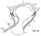
[0095] FIG. 2 distracts the femoral head FH in a direction away from the acetabulum A, thereby creating a
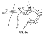
[0096]現在の伸延技法が抱えている課題を克服するために、本発明によれば、関節を内部伸延させるための方法および装置であって、外部牽引を適用する必要がない方法および装置が提供される。好ましい実施形態では、本発明により、互いに対向している骨と骨の間の関節の内部に配置することができ、かつ、関節を伸延させるために流体を使用して膨張させることができる水圧式伸延デバイス、例えばバルーンが提供される。図3は、股関節にバルーンを引き渡すための可能入口門のいくつかを示したものである。図3は、大腿頭部FHが寛骨臼Aによりかかっている股関節の上面図である。関節空間は、嚢Cおよび縁Lによって覆われている。股へのアクセスは、側面および関節の後方に沿って後側面門PLPにバルーンを挿入することによって、あるいは側面および関節の前方に沿って前外側門ALPにバルーンを挿入することによって得ることができる。バルーンおよび関連する器具は、ポートまたはカニューレを介して、あるいはセルディンガー様挿入または経皮的挿入などの侵襲性が最も小さい技法を使用して関節空間の中に引き渡すことができ、あるいは静脈切開手順を使用することも可能である。図4A〜4Eは、股関節へのアクセスを得ることができる様子を示したものである。 [0096] In order to overcome the problems posed by the current distraction techniques, according to the present invention, there is provided a method and apparatus for distracting joints internally, wherein no external traction needs to be applied. Provided. In a preferred embodiment, according to the invention, a hydraulic system can be placed inside the joint between bones facing each other and can be expanded using a fluid to distract the joint A distraction device, such as a balloon, is provided. FIG. 3 shows some of the possible portals for delivering the balloon to the hip. FIG. 3 is a top view of the hip joint on which the femoral head FH rests by the acetabulum A. FIG. The joint space is covered by the capsule C and the rim L. Access to the crotch can be obtained by inserting a balloon into the posterior lateral portal PLP along the side and posterior to the joint, or by inserting a balloon into the anterolateral portal ALP along the lateral and anterior of the joint . The balloon and associated instruments can be delivered into the joint space through ports or cannulas or using minimally invasive techniques such as Seldinger-like or percutaneous insertion, or a phlebotomy procedure It is also possible to use 4A-4E illustrate how access to the hip joint can be obtained.
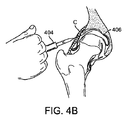
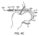
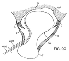
[0097]股関節への経皮的アクセスは、皮膚を介して、また、嚢Cを貫通して関節空間406の中へ前進する17ゲージ針などの針(図には示されていない)を使用して開始される。これは、X線透視検査法または他の画像化システムを使用して観察することができる。次に、任意選択で、空間に生理的食塩水を注入することによって嚢が拡張される。針が所定の位置に位置すると、ガイドワイヤGWまたはスイッチングワイヤが針を介して関節空間の中へ前進する。次に、針が抜き取られ、ガイドワイヤGWが所定の位置に残される。ガイドワイヤGWは、レールとして作用し、このレールに沿って他の器具を関節空間に引き渡すことができる。図4Aでは、テーパが施された末端408を有する管状シースまたはカニューレ402がガイドワイヤGWに沿って関節空間406の中へ前進している。テーパが施された末端408は、シースが嚢Cの層を通過し、嚢Cの層に貫入するのを補助している。シース402の内側にバルーンカテーテル(図4C)がぴったりと収まっており、また、シースは、バルーンを引き渡している間、バルーンがそのプロファイルを最小に維持するのを補助し、かつ、バルーンの保護を補助するべくバルーンを拘束している。図4Bでは、任意選択で、嚢Cの拡張を補助し、それにより追加作業空間を生成し、かつ、嚢を介したガイドワイヤおよび/またはカテーテルの通過を容易にするために、バルーンカテーテルを引き渡す前、バルーンカテーテルを引き渡している間、あるいはバルーンカテーテルを引き渡した後に、針を備えた注射器404または他の注入デバイスを使用して生理的食塩水などの流体を関節空間に注入することができる。また、縁によって生成されたシールを破壊し、かつ、中央コンパートメントに流体圧力を導入することにより、同じく、バルーンカテーテル412の挿入を可能にするだけの十分な関節の伸延が補助される。シース402は、図4Cに示されているように、収縮したバルーン414を備えたカテーテル412を関節空間の中へ運んでいる。シース402が配置されると、図4Dに示されているように、収縮したバルーン414をその遠位端に有するカテーテル412をシースを介して前進させ、かつ、露出させることができる(あるいは別法としてシースを後退させることも可能である)。カテーテルの遠位端は、カテーテルが、関節性軟骨または周囲の組織を損傷することなく、湾曲した関節空間の周囲を容易に前進することができるように適合された非外傷性遠位チップ416を有することができる。さらに、バルーン414は、靭帯または関連する組織を損傷することなく、靭帯円筋LTの後方まで前進して配置される。他の状況では、場合によっては靭帯円筋の前方にバルーンを配置することが望ましく、また、さらに他の状況では、フォーク形のバルーンを使用して靭帯円筋の両側を通過させることも可能である(以下で開示されている)。次に、生理的食塩水、造影剤、それらの2つの組合せによってバルーン414が膨張する。ガス状の膨張流体を始めとする他の流体を使用することも可能である。この膨張は図4Eに示されている。バルーンは、膨張すると、大腿頭部FHを寛骨臼Aから離れる方向に伸延させ、それにより関節空間406が広くなる。バルーンの膨張は、靭帯円筋、近傍の血管系、神経あるいは隣接する他の組織を損傷することなく実施される。バルーンは、約10mmないし12mmまたはそれ以上の空隙を生成することが好ましい。次に、関節または周囲の組織に対する診断または治療手順を実施することがきるよう、同じカニューレまたは異なるカニューレを介して関節空間の中に関節鏡検査器具410を前進させることができる。
[0097] Percutaneous access to the hip joint uses a needle (not shown) such as a 17 gauge needle to advance through the skin and through the capsule C and into the
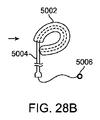
[0098]好ましい実施形態では、バルーンは、関節の中へ前進し、膨張すると寛骨臼窩AFの中にバルーンが位置するように膨張する。寛骨臼窩は、寛骨臼内の凹状領域であり、天然のくぼみを提供しており、このくぼみの中にバルーンを配置してバルーンを安定にし、バルーンが膨張する際のその移動、および関節が操作される際のバルーンの移動を抑制することができる。図4Fは、膨張したバルーンが寛骨臼窩の中に位置している様子をより詳細に示したものである。バルーンは、膨張している間、および関節が伸延している間、窩の中に留る。図4Gは、関節空間の中を見た寛骨臼Aおよび窩Fの図であり、大腿頭部は除去されている。点線で示されているバルーン414は、窩の中に位置しており、寛骨臼の周囲の最小の表面と重畳している。さらに、以下でより詳細に説明するように、バルーンが膨張して関節が伸延している間、関節の位置を変更し、関節空間にさらにアクセスするために股を操作することができる。
[0098] In a preferred embodiment, the balloon is advanced into the joint and expands so as to position the balloon within the acetabular fossa AF. The acetabular fossa is a concave area in the acetabulum and provides a natural depression into which the balloon is placed to stabilize the balloon and its movement as the balloon is inflated, and The movement of the balloon when the joint is manipulated can be suppressed. FIG. 4F shows in more detail how the inflated balloon is located in the acetabular fossa. The balloon remains in the fovea while expanding and while the joint is distracting. FIG. 4G is a view of acetabulum A and fovea F looking into the joint space, with the femoral head removed. A
[0099]関節組織の最大視程および関節組織への最大アクセスを可能にするためには、関節表面と接触するバルーンの面積が最小化されることが好ましい。それと同時に、バルーンによって提供される伸延力は、バルーン接触面積とバルーン圧力の積であるため、異常に大きいバルーン圧力を回避するためには十分な接触面積を提供しなければならない。図5Aは、接触領域が最小化された状況を示したものである。図5Aでは、軸3908の遠位端の近傍の球形バルーン3906が、寛骨臼Aと大腿頭部FHの間の関節空間の中で膨張している。球面形バルーン3906が膨張して寛骨臼A上の接触点3902で関節表面に接触し、また、大腿頭部FH上の接触点3904で同じく接触している。これにより、関節空間への比較的邪魔のないアクセスが提供される。しかしながら接触領域3902、3904は極めて小さいため、関節を伸延させるための適切な力を提供するためにはバルーン圧力が極めて高くなる。バルーンは、バルーンを一定の体積まで膨張させることができるよう、一般に、弾力性のない非膨張性材料で構築されることが好ましい。図5Bは、このようなバルーンを膨張させるとどうなるかを示したものである。バルーン3906aの接触領域3902a、3904aは、バルーンが膨張するにつれて平らになり、関節表面の形と同じ形になる。バルーンが平らになるため、関節空間へのアクセスは、図5Aの場合より制限されており、さらには接触領域3902a、3904aがより大きいため、関節を伸延させるために必要なバルーン圧力がより低い。図5Cは、バルーン接触領域と関節アクセスを平衡させる実施形態を示したものである。図5Cでは、円筒状の形のバルーン3906bが軸3908に結合されており、寛骨臼Aと大腿頭部FHの間の関節空間まで前進している。バルーン3906bの円筒状ボディは、それぞれ寛骨臼Aおよび大腿頭部FHと係合する比較的大きい平らな上部接触領域3902bおよび比較的大きい平らな下部接触領域3904bを提供している。接触領域3902b、3904bは十分に大きく、したがって、伸延させている間、適切なバルーン圧力を使用することができ、かつ、それと同時に、依然として関節空間への比較的邪魔のないアクセスが許容される。個々の関節表面に対するバルーンの総接触領域は、その関節表面の総面積の約50%以下であることが好ましい。股関節の場合、接触領域は、バルーンが膨張した場合の窩の外側の寛骨臼の総表面積の約50%以下であることが好ましく、また、約30%未満であることがより好ましい。
[0099] In order to allow maximum visibility of joint tissue and maximum access to joint tissue, it is preferred that the area of the balloon in contact with the joint surface be minimized. At the same time, the distraction force provided by the balloon is the product of the balloon contact area and the balloon pressure, so it must provide a sufficient contact area to avoid abnormally high balloon pressure. FIG. 5A shows the situation where the contact area is minimized. In FIG. 5A, a
[0100]好ましい実施形態では、バルーンは、約800mm2以下の総接触領域にわたって寛骨臼と接触し、また、接触領域は、バルーンが膨張した場合の窩の外側の寛骨臼の表面積の約50%以下であることが好ましく、約30%未満であることがより好ましい。一方、バルーン接触領域は、関節を伸延させるために極端に高い圧力が必要であり、そのために極端に高い破裂圧力を有するバルーンを必要とするほどには小さくはならない。好ましい実施形態では、バルーンは、約20気圧(300psi)を超えない圧力、より好ましくは約7気圧(100psi)を超えない圧力、また、最も好ましくは約5気圧(75psi)を超えない圧力で関節を伸延させるだけの十分な力を生成することができ、好ましくは少なくとも13.61kg(30ポンド)の力、より好ましくは少なくとも22.68kg(50ポンド)の力、また、最も好ましくは少なくとも34.02kg(75ポンド)の力を生成することができる。したがって、好ましい実施形態では、互いに対向している個々の関節表面に対するバルーンの総接触領域は、約200mm2(0.3平方インチ)ないし800mm2(1.2平方インチ)である。追加バルーン実施形態が以下で開示されている。これらの所望の動作条件のため、商用的に入手することができるバルーンカテーテルのほとんどは、関節を伸延させるためには適していない。詳細には、心臓血管バルーンは、通常、所望する十分に低い圧力まで関節を伸延させることはできない。さらに、商用的に入手することができるバルーンの多くは極めて長いことがしばしばであり、したがって関節空間に適切に嵌合しない可能性があり、窩の中に確実に位置しない可能性があり、あるいはそれらが作業領域を妨害し、あるいは膨張している間にそれらが関節から追い出される可能性がある。 [0100] In a preferred embodiment, the balloon contacts the acetabulum over a total contact area of about 800 mm 2 or less, and the contact area is about the surface area of the acetabular surface outside the fovea when the balloon is inflated. It is preferably 50% or less, more preferably less than about 30%. The balloon contact area, on the other hand, requires extremely high pressure to distract the joint, and therefore is not small enough to require a balloon with extremely high burst pressure. In a preferred embodiment, the balloon is articulated at a pressure not exceeding about 20 atmospheres (300 psi), more preferably not exceeding about 7 atmospheres (100 psi), and most preferably not exceeding about 5 atmospheres (75 psi). Can produce sufficient force to distract, preferably at least 13.61 kg (30 pounds), more preferably at least 22.68 kg (50 pounds), and most preferably at least 34. A force of 02 kg (75 pounds) can be generated. Thus, in a preferred embodiment, the total contact area of the balloon with the individual articulating surfaces facing each other is about 200 mm 2 (0.3 square inches) to 800 mm 2 (1.2 square inches). Additional balloon embodiments are disclosed below. Because of these desired operating conditions, most commercially available balloon catheters are not suitable for distracting joints. In particular, the cardiovascular balloon usually can not distract the joint to the desired low pressure. Furthermore, many of the commercially available balloons are often quite long and may therefore not fit properly in the joint space and may not be reliably located in the fovea, or They can be driven out of the joint while they obstruct the work area or are inflated.
[0101]関節が伸延されると、バルーン伸延デバイスが除去された後の関節表面の分離を維持するために、図6に示されているようなスペーサ4202を関節空間の中に配置することができる。スペーサ4202には、寛骨臼Aの曲率と整合する曲率を有する上部表面4204、および大腿頭部FHの曲率と整合する曲率を有する下部表面4206が含まれている。輪郭を整合させることにより、関節表面の損傷の防止が促進され、また、力が接触表面に沿ってより一様に分散される。上部表面および下部表面は、軟らかい材料によってパッドを当てがうか、あるいは覆うことによって損傷を最小化することができる。ポスト4208によって両方の表面が分離される。ポスト4208は、円形、楕円形、正方形または他の断面プロファイルを有することができる。ポスト4208は、垂直方向に移動させることができ、あるいは垂直方向に調整することができるため、上部表面と下部表面の間の距離を変化させることができる。スペーサ4202は、外科手術によって埋没させることができ、あるいはより好ましくはカニューレを介した関節鏡検査法によって引き渡し、次に、インサイチューでアセンブルするか、あるいは膨張させることも可能である。スペーサは、スペーサが配置された後のアセンブリの安定性を保証するための固定機構を有することができる。いくつかのケースでは、関節をさらに伸延させ、それによりスペーサ4202を引き渡し、かつ、配置するための追加空間を提供するために、場合によっては伸延バルーンを過剰に膨張させることが有利である。スペーサが所定の位置に配置されると、次に伸延デバイスを収縮させることができる。スペーサ4202の除去は、スペーサ4202を関節空間から除去することができるよう、伸延デバイスをもう一度挿入し、かつ、十分に膨張させることによって達成することができる。別法としては、外部伸延を使用してスペーサを挿入し、あるいは除去することも可能である。
[0101] Placing a
[0102]もう一度図4E〜4Fを参照すると、バルーン414が所定の位置に配置され、かつ、関節が伸延されると、関節内の目標構造に対する最適視程およびアクセスを得るために関節を操作することができる。このような操作には、股関節の屈曲(前方および上方への大腿骨の曲げ)および伸展(まっすぐに伸ばすこと)、外旋(身体の中心から離れる方向の外部回転)および内旋(身体の中心に向かう内部回転)、ならびに関節の外転(身体の正中線から離れる方向の側方運動)および内転(身体の正中線に向かう内側運動)を含むことができる。膨張したバルーンのサイズ、形状および曲率により、バルーンを著しく移動させることなく、あるいはバルーンを著しく離脱させることなく、伸延した構成で股関節を操作することができる。一例示的実施形態では、バルーンは、関節表面との接触が関節の中央領域に集中し、関節の周囲の近傍のバルーンの周りの表面を非拘束状態にすることができるよう、関節(例えば窩)の中心に配置することができる、外部表面が一様に凸状の、好ましくは球面状である、二叉ではないコンパクトな形状にすることができる。この形状によって支柱が提供され、この支柱の周りに互いに対向する骨を回転させることができ、それにより関節の運動に対するあらゆる障害が最小化される。さらに、膝504を屈曲または伸展させることができるため、より広範囲にわたる股関節の運動が許容される。通常、股は少なくとも最大約30°まで側方に回転させることができ、少なくとも最大約40°まで内側に回転させることができ、少なくとも最大約20°まで伸展させることができ、少なくとも最大約140°まで屈曲させることができ、少なくとも最大約50°まで外転させることができ、また、少なくとも最大約30°まで内転させることができる。膝を曲げ、かつ、股を屈曲させることにより、外旋を最大約50°まで大きくすることができ、外転を約80°まで大きくすることができ、また、内転を約20°まで小さくすることができる。図7は、患者の股関節の屈曲F、伸展E、内旋MR、外旋LR、外転ABおよび内転ADを示したものである。関節空間へのさらなるアクセスの提供に加えて、股関節の操作によって同じく様々な組織が弛緩し、したがって関節へのより良好なアクセスが得られる。例えば、股関節を屈曲させることによって前方関節嚢に対する張力が解放され、したがって縁および隣接する他の関節構造へのより良好なアクセスが得られる。外部牽引によって関節を伸延させる従来の牽引方法は、嚢を弛緩させるための股関節の実質的な屈曲を妨げており、したがってバルーン伸延手順は、従来の牽引方法よりも有利である。さらに、本発明による方法は、関節が伸延している間に股関節の追加操作を実施することができるため、同じく従来の伸延方法よりも有利である。関節空間への所望のアクセスを提供するために股関節が広範囲にわたる運動で所望の位置まで伸延され、かつ、操作されると、図8に示されているような脚装具502を使用して患者の脚を所望の位置に保持することができる。脚装具の一方の末端は、患者の腿または脚の下方に取り付けることができ、また、もう一方の末端は、手術台または他の支持構造に取り付けることができる。脚装具は、自立型にすることも、あるいは患者の上半身および/または脚の下方に固定することも可能である。
[0102] Referring again to FIGS. 4E-4F, manipulating the joint to obtain optimal visibility and access to the target structure in the joint once the
[0103]図9A〜9Iは、股関節にアクセスし、かつ、股関節を伸延させるための方法の好ましい一実施形態を示したものである。図9Aは、転子T、および寛骨臼Aの中に配置された大腿頭部FHを有する大腿骨によって形成された股関節の上面図である。寛骨臼は、靭帯円筋(簡潔にするために図には示されていない)が取り付けられる寛骨臼窩AFとして知られている凹領域を有している。また、関節は縁Lからなっており、嚢Cによって取り囲まれている。図9Aでは、除去可能な鋭い内部コアを有する、17Gであることが好ましい針4002が、嚢を介したX線透視検査法によるガイダンスの下で関節の周辺コンパートメントの中に配置されている。前外側ポートまたは後側面ポートは、関節にアクセスするために使用することができる。針は、大腿頚に対して平行に挿入され、かつ、大腿頚と接触し、また、大腿頭部の主湾曲に対して概ね接線をなしていることが好ましい。このようにすることにより、周辺コンパートメント中への針の安全な挿入の保証が促進され、また、縁および大腿頭部が接触するポイントとの針の整列が促進される。所定の位置に配置されると鋭い内部コアが除去され、また、図9Bには、嚢を拡張してより広い作業空間を生成するために、針4002を介した周辺コンパートメント中への生理的食塩水4004の注入が示されている。次に、図9Cに示されているように、ガイドワイヤGWまたはスイッチングワイヤが針4002を介して関節空間の中へ前進し、次に針が除去され、図9Dに示されているようにガイドワイヤGWのみが所定の位置に残される。次に、図9Eは、ガイドワイヤGWに沿って関節空間の中へ前進した、カニューレが挿入された栓子4008を示したものである。カニューレ4006の直径は5mmであることが好ましく、また、カニューレ4006は分割カニューレである。バルーンが挿入されると、分割カニューレを除去した後、バルーンと共にもう一度挿入することができ、また、同じアクセスポートを使用してスコープまたは他の関節鏡検査ツールを挿入することができる。カニューレ4006から栓子4008が除去され、次に、カニューレ4006の中に挿入器4010が置かれる。挿入器は、関節表面または他の組織を損傷しないよう重合体から製造されることが好ましく、また、挿入器は可撓性で、かつ、押し込むことが可能であり、したがって図9Fに示されているように縁Lを通り越して関節空間の中央コンパートメントの中へ前進させることができる。挿入器4010は、その幅を約2〜4mmにすることができ、また、約1〜3mmの厚さを有しており、かつ、バルーン伸延デバイスを受け取るようにサイズ化されている。また、挿入器は、流体を先端から分散させることができる中央管腔を有することも可能である。いくつかの実施形態では、挿入を容易にするために予め挿入器の形を大腿頚の輪郭の形にすることができる。
[0103] Figures 9A-9I illustrate a preferred embodiment of a method for accessing and distracting a hip joint. FIG. 9A is a top view of a hip joint formed by a femur having a trochanter T and a femoral head FH disposed in an acetabulum A. FIG. The acetabulum has a concave area known as the acetabular fossa AF to which the ligamentum dorsum muscle (not shown in the figure for the sake of simplicity) is attached. Also, the joint consists of a rim L and is surrounded by a capsule C. In FIG. 9A, a
[0104]次に、縁Lの下方の大腿頚の輪郭に沿って、縁Lと大腿頭部FHの間の真空シールが破壊されるまで挿入器4010が前進する。挿入器4010の先端は、縁の下方の通過を補助するために平らにすることができる。挿入器が縁の下方を通過するのを補助するために、手で股関節に若干の牽引または操作を加えることができる。また、挿入器から流体を注入して縁の通過を補助することも可能である。また、関節空間に注入される生理的食塩水4004は、真空シールを破壊するための中央コンパートメントへの流体の容易な流入を補助するための界面活性剤を含むことも可能である。縁Lおよび大腿頭部FHのシールが破壊されると、図9Gに示されているように、先端が関節の中央コンパートメント内に到達するまで挿入器4010が前進する。挿入器の前進は、ガイダンスを補助するためにX線透視検査法を使用して視覚化することができる。次に、その遠位端の近傍に膨張可能バルーン4014を有する伸延デバイス4012が挿入器4010を介して中央コンパートメントの中へ前進し、挿入器4010が除去される。また、バルーン伸延デバイス4012は、任意選択で、前進中のデバイスへの剛性の提供を補助する補強軸4016あるいは金属スタイレットを有することも可能である。図9Hに示されているように、補強軸4016は、その遠位端が中央コンパートメントの縁に位置するまで伸延デバイス4012内の管腔の中を前進し、一方、収縮したバルーン4014は、中央コンパートメントの中まで前進する。バルーン4014は、関節空間内の所望の位置、好ましくは窩AFまで前進する。次に、図9Iに示されているように、金属軸4016が除去され、バルーン4014が膨張して関節が伸延する。関節は、約10〜12mm伸延させることが好ましく、そのためには、窩のくぼみのため、また、伸延力の方向の性質のため、場合によってはより大きい直径、例えば17mm以上バルーンを実際に膨張させなければならない。
[0104] Next, along the contour of the femoral neck below the rim L, the
[0105]例えば図10Aは、寛骨臼に対して概ね直角であり、また、大腿頭部に対して同じく直角であるベクトル4104に沿って股関節を伸延させる膨張したバルーン4102を示したものである。図10Bに示されているようにベクトル4104をその水平方向の成分4108および垂直方向の成分4106に分解すると、実際の水平方向または垂直方向の変位は、ベクトル4104に沿った総変位よりはるかに小さくなることは明らかである。したがって関節の所望の垂直方向または水平方向の変位を得るためには、関節表面に対して直角の方向により大きく関節を伸延させなければならない。単純な三角法を使用して伸延ベクトル4104の成分を計算することができる。さらに、量が異なる伸延または方向が異なる伸延をもたらすことになる異なる伸延力ベクトルを提供するために、伸延バルーンを関節空間の中で収縮させて移動し、かつ、もう一度膨張させることも可能である。
[0105] For example, FIG. 10A shows an inflated balloon 4102 distracting the hip joint along a
[0106]伸延バルーンには、伸延バルーンを窩の中に容易に位置させることができ、また、伸延バルーンを窩の中で容易に保持することができる様々な形状および/または特徴を持たせることができる。例えば図11Aでは、バルーン606は、作業長さ602に近位テーパ領域および遠位テーパ領域の長さを加えた長さを含む総合軸方向長さを有している。作業長さ602は、バルーンの長さのうちの関節表面と接触する部分であり、テーパは含まれていない。バルーンは膨張直径604を有しており、この膨張直径604は約15〜30mmであることが好ましく、また、約20〜27mmであることがより好ましい。作業長さ602の範囲は、直径604の長さの約0.8倍ないし1.3倍であることが好ましく、また、直径604の長さの約0.75倍ないし1.25倍であることがより好ましく、また、とりわけ好ましい実施形態では、この長さは実質的に直径に等しい。それにより、窩の中に位置させることができる概ね円筒状の、短く、かつ、ずんぐりしたバルーン606が得られ、また、そのコンパクトなサイズのため、バルーンの後ろ側の関節の表面を視覚化することができ、また、その表面に対してバルーン全体の周囲にアクセスすることができる。また、この形状により、限られた関節空間内でバルーン全体を挿入器シースまたはアクセスカニューレ(使用されている場合)から遠位方向に確実に前進させることができるよう補助される。
[0106] The distraction balloon has various shapes and / or features that allow the distraction balloon to be easily positioned in the fovea and to be easily retained in the fovea. Can. For example, in FIG. 11A, the
[0107]バルーン606は、短い遠位チップ614を有するカテーテル軸608に取り付けられている。バルーンは、バルーンが非迎合的または半迎合的になり、かつ、概ね一定の体積になるまで膨張するよう、非弾力性であることが好ましい様々な材料を使用して製造することができる。可能な材料には、ナイロン、PET、ポリウレタン、あるいはシリコーンまたはラテックスなどのより非迎合性の材料がある。バルーン壁の厚さは、0.0033cm(0.0013インチ)から0.0051cm(0.0020インチ)までの範囲であることが好ましい。遠位チップ614は、関節組織の損傷を防止するために、ソフト・デュロメータ・ポリマーであってもよい。この実施形態と共に使用することができ、あるいは本明細書において開示されているバルーン実施形態のうちの任意の実施形態と共に使用することができる他の可能チップ構成については、以下でさらに詳細に開示されている。軸608は単一の膨張管腔を有することができ、あるいはより好ましくは、軸608は、バルーンを膨張させるための管腔612、およびガイドワイヤ、流体注入あるいは他の器具を通過させるための第2の管腔610の少なくとも2つの平行管腔を有している。また、軸は、同心の管腔を有することも可能である。図11Bは、図11Aの線A−Aに沿って取った軸608の断面を示したものであり、また、図11Cは、図11Aのバルーンの斜視図を示したものである。図11Dは、平面654に沿って取ったこの実施形態の接触領域652を示したものである。
The
[0108]同様の実施形態では、バルーンの形状は、円筒状の形をしたボディの代わりに、球面状の形をしているか、あるいは球面に近い形をしている。図11Eは、図11Aの実施形態の寸法と同様の寸法を有する球面状の形をしたバルーン606aを示したものである。曲率半径は、実質的に関節表面の曲率半径以下であることが好ましい。股関節の場合、寛骨臼は、約8mmから16mmまでの範囲の曲率半径を有している。したがってバルーンは、好ましくは窩の上にその中心を置いて、単一の連続領域内で寛骨臼と係合する。
[0108] In a similar embodiment, the shape of the balloon is spherical or near spherical instead of cylindrically shaped body. FIG. 11E shows a spherically-shaped
[0109]図12は、伸延バルーンの他の実施形態を示したものである。図12では、バルーン704は、半球、半楕円またはマウンドの形をした上方領域708を有しており、また、実質的に平らな下方領域710をその反対側に有している。また、下方領域710は、上方領域よりはるかに大きい半径を有することも可能であり、それにより上方領域に対して比較的より平らな下方領域を得ることができる。バルーン704は、上向きの方向に優先的に膨張し、その反対側の下側は比較的平らな状態あるいはより大きい曲率半径を維持するように構造化することができる。より球根状の、より半径が小さい上側は、窩の中に位置するように適合されており、一方、より平らな下方側は大腿頭部と係合する。バルーン704は、単一の膨張管腔を有することができ、あるいは本明細書において説明されている多重管腔構成のうちの任意の多重管腔構成を有することができる軸702に取り付けられている。遠位チップ706は、軟らかいチップであることが好ましいが、本明細書において開示されているチップ実施形態のうちの任意のチップ実施形態を含むことも可能である。
[0109] FIG. 12 shows another embodiment of a distraction balloon. In FIG. 12, the
[0110]図13A〜13Cは、伸延バルーンのさらに他の実施形態を示したものである。図13Aでは、バルーンには、上方部分804および下方部分806が含まれている。バルーン全体は、目玉焼きまたは空飛ぶ円盤のような形をしている。上方部分804は、中央ドームまたは中央球根状チャンバを有しており、また、下方部分806は、環状またはドーナツの形をした領域であり、中央ドームを取り囲んでいるか、あるいは中央ドームを部分的に取り囲んでいる。上方部分804は、下方部分806には無関係に膨張させることができることが好ましく、したがってこれらの2つの部分は、バルーン内の内部メンブランによって互いに流体的に隔離されており、したがって軸802の中には少なくとも2つの膨張管腔が提供されることになる。別法としては、これらの2つの部分を一体で膨張させることも可能であり、その場合、これらの2つの部分は、互いに流体的に相互接続され、軸802の中に必要になるのは単一の膨張管腔のみである。上方領域および下方領域は、上向きおよび下向きの両方に対称の形を有することができ、あるいはいずれか一方または両方の領域は、より平らな底面および膨張するとより丸く、かつ、より広くなる上面を有することができ、この上面は、窩および寛骨臼の凹状表面の形と一致するように適合されている。中央チャンバは、窩の中に位置するようにサイズ化および形状化されており、一方、環状部分は、窩を取り囲んでいる関節表面と係合するように適合されており、それにより窩の中でバルーンが安定する。また、カテーテル軸は、軟らかい非外傷性チップ808または本明細書において開示されているチップのうちの任意のチップを有することも可能である。図13Bは、図13Aの伸延バルーンカテーテルの上面図を示したものであり、また、図13Cは、図13Aの線A−Aに沿って取った軸802の断面を示したものである。図13Cでは、軸802は、3つのパイ形管腔810、812、814を有している。これらのうちの2つを使用してバルーンの上方部分804および下方部分806を膨張および収縮させることができ、また、第3の管腔をガイドワイヤ、洗浄または他の器具のために使用することができる。
[0110] Figures 13A-13C illustrate yet another embodiment of a distraction balloon. In FIG. 13A, the balloon includes an
[0111]図14A〜14Bは、伸延バルーンカテーテルのさらに他の実施形態を示したものである。図14Aでは、バルーンには、パンケーキまたは平円盤状の形あるいはロリポップの形をしたメインボディ906が含まれており、メインボディ906の長手方向のリッジまたは管状チャンバ904は、メインボディ906の上側に沿って軸方向に延在している。代替実施形態では、メインボディの下方の表面も、同じく、メインボディに沿って軸方向に延在している長手方向のリッジまたは管状チャンバを含むことができる。リッジは、バルーンが窩の中に容易に位置することができるよう、メインボディの表面から突出している。他の実施形態の場合と同様、メインボディ906は、管状チャンバ904と共に、あるいは管状チャンバ904には無関係に膨張させることができる。バルーンは、軸902の遠位部分に取り付けられており、軟らかい非外傷性チップ908が含まれている。軸は、本明細書において説明されている管腔構成のうちの任意の管腔構成を有することができ、また、チップは、本明細書において説明されているチップ構成のうちの任意のチップ構成を含むことができる。図14Bは、図14Aに示されているバルーンの上面図である。
[0111] Figures 14A-14B illustrate yet another embodiment of a distraction balloon catheter. In FIG. 14A, the balloon includes a
[0112]図15は、伸延バルーンの他の例示的実施形態を示したものである。バルーン1006は非対称にテーパが施されており、アーモンドの形または涙滴の形を有している。バルーンは、近位テーパ1010とは異なる遠位テーパ1008を有することができる。好ましい実施形態では、バルーンの近位端はより浅いテーパを有しており、また、遠位端はより急峻なテーパを有している。また、図16に示されているように、バルーンの遠位端は、膨張すると丸く、かつ、凸状にすることができる。このような形にすることにより、窩の中へのバルーンの配置が促進される。より浅い近位テーパは、約10度ないし45度の範囲であることが好ましく、一方、遠位テーパは、約30度ないし90度の範囲であることが好ましい。軸1002および遠位チップ1004は、本明細書において開示されている特徴のうちの任意の特徴を含むことができる。図16は、凸状の遠位端を有する伸延バルーンの他の実施形態を示したものである。図16では、遠位バルーン壁1104がバルーンの中にめくり返されており、また、バルーンの外部表面は軸1102に取り付けられており、それにより膨張するとバルーン上に凸状の遠位領域1108が形成される。この構成の利点の1つは、バルーン上の遠位テーパが除去され、したがって遠位テーパに適応するための余分の長さを必要とすることなく、関節表面と係合するバルーンの作業表面がカテーテルの遠位チップの極めて近傍に位置することである。任意選択で、本明細書において開示されている遠位チップ特徴または軸特徴のうちの任意の遠位チップ特徴または軸特徴をこのバルーン構成と共に容易に使用することができる。さらに他の実施形態では、近位テーパおよび遠位テーパを逆にすることも可能である。例えば図17は、遠位テーパ1202の方が近位テーパ1204より浅い一実施形態を示したものである。バルーンは、本明細書において開示されているチップのうちの任意のチップであってもよい遠位チップ1208を有する軸1206に取り付けられている。近位テーパおよび遠位テーパの範囲は、上で開示した範囲と同様であるが、それらは上で開示した範囲とは逆である。この実施形態は、バルーンが膨張する際に、最大直径を有する近位部分が窩の中に位置するまでバルーンがバルーン自体を遠位方向に押す傾向を示すことができる利点を有することができる。したがってバルーンによって占有されていない関節の前方部分が残され、視覚化および器具アクセスのための最大空間が提供される。
[0112] FIG. 15 illustrates another exemplary embodiment of a distraction balloon. The
[0113]図18は、軸4304の遠位部分に結合されたドーナツ形バルーン4302を示したものである。ドーナツの中央陥凹領域4306は、力を分散させ、かつ、大腿頭部を位置させるための一様な接触表面を提供し、それにより関節空間内におけるバルーンの安定化が促進されるため、有利である。さらに、ドーナツの外部凸状表面4308も同様に力を分散させる接触リングを提供し、また、寛骨臼に対する上部表面の安定化を促進している。図19は、バルーン4404が救命具または浮袋のような形をしており、また、バルーンの中央部分を端から端まで延在している開口4406を有している点を除き、図18の実施形態と同様の実施形態を示したものである。バルーン4404は軸4402に結合されており、また、遠位チップ4408は、外側に向かって平らな朝顔の形に広がっており、関節空間を介した前進を容易にするために幅の広い、薄い前縁を提供している。また、図20も同じく救命具または浮袋の形をしたバルーン4504を示したもので、バルーン4504は軸4502に取り付けられている。この実施形態には、バルーンの中心部分にウェブ領域4506が含まれている。遠位チップ4508も同じく朝顔の形に広がった平らな領域である。ウェブ領域4506によって関節性表面を関節の残りの部分から隔離することができ、したがって表面の修復を補助するために重合物質を関節性表面に引き渡し、光または熱あるいは他の手段によって重合させることができる。別法としては、軟骨細胞、間充織幹細胞、成長因子、等々などの生物活性物質、または他の治療薬品を隔離領域に引き渡して治癒を刺激することも可能である。
[0113] FIG. 18 shows a
[0114]いくつかのバルーン実施形態は、関節を伸延させるだけではなく、関節の一部を隔離し、組織の視覚化または修復を容易にする乾いた領域を生成する。例えば図21Aは、開いた中央領域を取り囲むことができるトロイド状またはドーナツの形をしたバルーン1302を示したものである。バルーンが関節の中で膨張すると、中央領域1318が関節の残りの部分から流体的に隔離されるよう、上部バルーン表面および下部バルーン表面が関節の表面と係合して密閉する。トロイド状の形をしたバルーン1302は、バルーンが膨張している間、隔離された領域1318への器具、治療薬品または他の物質の挿入を容易にする方法で軸1308に取り付けられることが好ましい。例えばバルーン1302は、トロイドの中心軸が軸の縦軸に対して直角になり(キャンディロリポップに似ている)、かつ、遠位非外傷性チップ1310を備えたバルーンの幅を横切って軸1308を延在させることができるように軸1308に取り付けることができる。軸1308は、隔離された領域1318の中に複数の管腔および遠位ポート1304を有しており、それらを介してデバイス、流体または他の物質を隔離された領域に挿入することができる。膨張ポート1306を介してバルーン1302を膨張させるために、少なくとも1つの管腔が使用される。図21Bは、図21Aの線B−Bに沿って取った軸1308の断面を示したものであり、膨張ポート1306および他のポート1304に結合することができる3つの管腔1312、1314、1316が示されている。図21Cは、図21Aの線A−Aに沿って取ったバルーン1320の断面を示したものである。
[0114] Some balloon embodiments not only distract the joint but also isolate a portion of the joint and create a dry area that facilitates tissue visualization or repair. For example, FIG. 21A shows a toroidal or donut shaped
[0115]図22Aは、関節の一部の領域を隔離し、かつ、流体の流入に対する障壁を提供する伸延バルーンの一代替実施形態を示したものである。図22Aでは、同様のトロイド状またはドーナツの形をしたバルーン1402が軸1410に取り付けられている。しかしながら、この実施形態では、軸の遠位端は、遠位ポート1406がバルーンの隔離された領域1404の中(トロイドの中心)に配置されるようにバルーンに結合されている。したがってカテーテル軸の先端から流体、器具または他の物質を隔離された領域の中に配置することができる。軸1410は複数の管腔を有することができ、それらのうちの1つは、バルーンの下方に軸を出している膨張ポート1408を使用してバルーンを膨張させるための管腔1414であり、また、少なくとも1つは、器具または他の物質を通過させるためのもっと大きい管腔1412である。図22Bは、図22Aの線A−Aに沿って取った軸1410の断面を示したものである。この実施形態の追加利点は、遠位軸の先端がバルーンによって保護され、したがって関節空間の中に軸を送付している間に軸が組織を損傷する可能性がより小さくなることである。
[0115] FIG. 22A illustrates an alternative embodiment of a distraction balloon that isolates a partial area of a joint and provides a barrier to fluid inflow. In FIG. 22A, a similar toroidal or donut shaped
[0116]伸延バルーンの一代替実施形態は、バルーンが膨張するとドームによって取り囲まれた隔離中空空間が生成されるよう、ドームの形を有することができる。図23Aは、軸1502に結合されたドーム形バルーン1502を示したものである。軸1502の遠位ポート1510からドーム内の中空空間1506に、器具、流体または他の物質を引き渡すことができる。また、軸1502は、バルーン1504に流体結合された膨張ポート1508を備えた膨張管腔を有しており、それによりバルーン1504を膨張させることができる。図23Bは、図23Aの線A−Aに沿って取った伸延バルーンの断面を示したものである。ドームの上部表面は、同様に、窩の輪郭と整合する形にすることができ、したがって膨張するとドームの形と窩の形が一致し、関節空間内におけるバルーンの安定化が促進される。図25A〜25Bは、ドーム形伸延バルーンの他の実施形態を示したものである。バルーン4702は、凹状の領域4706を有する鐘またはドームのような形をしている。図25Aは、バルーン4702の斜視図を示したものであり、また、図25Bは、図25Aの中心線断面図を示したものである。
[0116] An alternative embodiment of the distraction balloon can have the shape of a dome such that expansion of the balloon creates an isolated hollow space surrounded by the dome. FIG. 23A shows a dome shaped
[0117]図24は、伸延バルーンのさらに他の実施形態を示したものである。バルーン4602は、楕円形または長円形の形をしており、また、軸4604に結合されており、任意選択で、朝顔の形に広がった平らなチップ4606を有している。楕円形のバルーンは、カテーテル軸の縦軸の周りに対称の形にすることができ、あるいは上部表面または下部表面をより平らにすることができる。
[0117] FIG. 24 illustrates yet another embodiment of a distraction balloon. The
[0118]図26A〜26Bは、3つの膨張可能バルーンを有する多重エレメントバルーン伸延デバイスを示したものである。一番上のバルーン4804、中央のバルーン4808および一番下のバルーン4810は、軸4802に結合されている。朝顔の形に広がった平らなチップなどの様々なチップ4806をデバイスの遠位端の上に置くことができ、あるいは本明細書において開示されている他のチップのうちの任意のチップを使用することができる。これらのバルーン4804、4808、4810の各々は、互いに独立して膨張させることができ、あるいは同時に膨張させることができる。さらに、個々のバルーンは、他のバルーンとは異なる固有の形状またはサイズを有することができ、あるいはそれらをすべて同じサイズにすることも可能である。バルーンは、同じ材料から製造することができ、あるいは可変材料特性を提供するために異なる材料から個々のバルーンを製造することができる。複数のバルーンをデバイス上に持たせることにより、バルーンを独立して膨張させて関節空間に嵌合させることができ、かつ、伸延の方向を最適化することができ、また、同じく、たとえバルーンのうちの1つが破裂しても、依然として関節の伸延が維持される追加利点を有している。図26Aは多重バルーンデバイスの端面図であり、また、図26Bは側面図である。さらに、デバイス上の複数のバルーンにより、可変量だけ関節を伸延させることができ、また、関節内の異なる位置で、異なる方向に関節を伸延させることができる。
[0118] Figures 26A-26B illustrate a multi-element balloon distraction device having three inflatable balloons.
[0119]バルーン伸延デバイスのさらに他の実施形態では、図27A〜27Cは、フォーク形のバルーンを示したものである。図27Aでは、対向可能バルーンエレメント4904、4906は、互いに離れる方向に外側に向かってバイアスされており、また、外部軸4902によって拘束されている。図27Bでは外部軸4902が後退して、対向可能バルーン4904、4906が露出しており、また、図27Cでは両方の対向可能バルーンエレメント4904、4906が膨張している。バルーンは、共通の膨張管腔または個別の膨張管腔に接続することができる。このフォーク形実施形態によれば、股などの関節空間の中にデバイスを挿入することができ、靭帯円筋の両側に伸延力を提供するために、靭帯円筋の互いに対向している側にバルーン4904、4906の各々を配置することができる。
[0119] In yet another embodiment of the balloon distraction device, Figures 27A-27C illustrate a fork-shaped balloon. In FIG. 27A, the
[0120]図28A〜28Bは、伸延デバイスの他の実施形態を示したものである。図28Aに示されているように、細長いソーセージの形をしたバルーン5002が、駆動機構5006を有する軸5004に結合されている。駆動機構5006を駆動し、この場合であれば軸の遠位端に結合されているケーブルを後退させることにより、バルーン5002および軸が図28Bに示されているようなトロイド状または半トロイド状の形に巻かれる。次に、使用中、トロイド状の形を維持するために駆動機構を所定の位置で固定することができる。代替実施形態は、トロイド状構成にある場合、バルーンの近位に軸を解放可能に結合する結合機構を軸の先端に有することができる(図には示されていない)。
[0120] Figures 28A-28B illustrate another embodiment of a distraction device. As shown in FIG. 28A, a
[0121]これらのバルーン実施形態は、すべて、伸延手順を実施している間の視覚化を補助するための放射線不透過性マーカをバルーンまたは軸の上に含むことができることは当業者には認識されよう。また、他のバルーン形状を使用して関節を伸延させることも可能であり、したがって本発明は、本明細書において開示されている例示的実施形態に限定されないことについても理解されよう。 Those skilled in the art will recognize that these balloon embodiments can all include radiopaque markers on the balloon or axis to aid in visualization while performing the distraction procedure. It will be done. It will also be appreciated that other balloon shapes can be used to distract joints, and thus the present invention is not limited to the exemplary embodiments disclosed herein.
[0122]窩空間の中にバルーンが位置するのを補助するためのバルーン幾何構造の使用に加えて、バルーン表面のコーティングおよび特徴を使用することも可能である。例えば、バンプ、突起またはリッジなどの表面特徴を、1つのファセット、または互いに対向している上部ファセットおよび下部ファセットを含む複数のファセットに加えることができ、あるいはバルーンのすべての表面に加えることができる。例えば、図29Aでは、バルーン1602には、その外部表面にバンプ1604が含まれており、一方、図29Bでは、外部バルーン表面1602は織って作られており1606、また、図29Cでは、バルーン1602の外部表面にリッジ1608が追加されている。さらに、関節空間中におけるバルーンの維持を補助するために、外部バルーン表面を粘着性の材料の層でコーティングすることも可能である。これらの特徴は、すべて、本明細書において開示されているバルーン実施形態のうちの任意のバルーン実施形態と組み合わせて使用することができる。
[0122] In addition to the use of balloon geometry to assist in locating the balloon in the foveal space, it is also possible to use coatings and features on the balloon surface. For example, surface features such as bumps, protrusions or ridges can be added to one facet, or multiple facets including upper and lower facets facing each other, or to all surfaces of the balloon . For example, in FIG. 29A the
[0123]また、バルーンを介して見ることができること、および一般的には関節鏡を使用してバルーンの後ろ側の関節の領域を観察することができることも内科医にとっては場合によっては重要である。したがってバルーンは、半透明である膨張流体を使用して膨張させることが好ましい。さらに、バルーンは、膨張流体の屈折率とほぼ同じ屈折率および/または関節空間内の流体の屈折率とほぼ同じ屈折率を有する材料で構築することができる。また、バルーンは、反射を小さくし、かつ、半透明性を改善する材料でコーティングすることも可能である。また、バルーンカテーテルの軸は、関節空間を照明することができる光ファイバまたは他の光源をその遠位端に含むことも可能である。光源は、バルーンの内部に配置することができ、あるいはバルーンの外部の、バルーンの近位または遠位のいずれかに配置することができる。図30は、カテーテル軸3302に取り付けられたバルーン3304の一例示的実施形態を概略的に示したものである。軸3302の中を通って延在している光ファイバ3308は、患者の外部に位置している、レーザ、LEDまたは他の適切な光源であってもよい光源3306から、バルーンの内部3310に光を引き渡しており、そこで関節を照明するために光が放出される。また、バルーンまたは軸は、関節の修復を容易にする他の特徴を有することも可能である。例えば図31では、大腿頭部FHが大腿骨の残りの部分から骨折5702している。内科医は、通常、ドリルで孔を穿ち、かつ、線5704に沿って、大腿骨を通って大腿頭部の中にねじまたはロッドを挿入することによってこのタイプの骨折を修復する。孔またはねじあるいはロッドを骨の中の深くまで前進させ過ぎると、ドリルビットまたはねじあるいはロッドが大腿頭部からはみ出し、寛骨臼の表面あるいは隣接する他の組織を損傷することになる。したがって軸5706の上に取り付けられ、かつ、中に、あるいは軸の遠位端の近傍にセンサ5710を有するバルーン5708を使用して、大腿頭部を貫通する直前のドリルまたはロッドあるいはねじを検出することができる。センサ5710には、超音波センサ、赤外線センサ、磁気センサ、容量センサまたは適切なセンサを使用することができる。別法としては、超音波映像装置をバルーン5708の中またはバルーン5708の近傍の軸5706に取り付け、それにより関節空間または周囲の組織の超音波映像を得ることができる。
Also, being able to see through the balloon and generally using an arthroscope to observe the area of the joint behind the balloon is also sometimes important to the internist . Thus, the balloon is preferably inflated using an inflation fluid that is translucent. Additionally, the balloon can be constructed of a material having a refractive index approximately the same as the refractive index of the inflation fluid and / or a refractive index approximately the same as the refractive index of the fluid in the joint space. The balloon can also be coated with a material that reduces reflection and improves translucency. The axis of the balloon catheter can also include an optical fiber or other light source at its distal end that can illuminate the joint space. The light source can be located inside the balloon, or it can be located outside the balloon, either proximal or distal to the balloon. FIG. 30 schematically illustrates an exemplary embodiment of a
[0124]また、送付している間、および関節から除去している間のバルーンのプロファイルも同じく重要である。伸延させる前の関節空間はとりわけ緊密であるため、可能な最低引渡し(送付)プロファイルをバルーンに提供することが望ましい。バルーンは整形が可能であり、収縮する際に最小プロファイルになるまで収縮するように補助し、それによりバルーンの挿入および回収を容易にする、ひだ、折り目あるいは他の特徴を有することができる。軸に沿ったバルーンの慎重な折畳みおよびシースされたバルーンの引渡しに加えて、低プロファイルの維持を補助するための他の機構を使用することも可能である。バルーンの近位端および遠位端は、滑らかな低摩擦コーティング材でコーティングすることができ、それによりカニューレ、シースまたは他のアクセスデバイス中へのバルーンの牽引を容易にすることができる。これらの他の機構は、バルーンを能動的に収縮させる。例えば図32Aでは、カテーテルには、内部軸1704、および内部軸1704の上に配置され、かつ、内部軸1704に対して回転させることができる外部軸1706が含まれている。バルーン1702の遠位端は内部軸1704に取り付けられており、また、バルーン1702の近位端は外部軸1706に取り付けられている。図32Bに示されているように、内部軸に対する外部軸の回転によってバルーン1702がねじれる。したがって、図32Cに示されているように、これらの軸の周りにバルーン1702が螺旋状に緊密に巻かれ、それにより最小のプロファイルが得られる。さらに、ねじり運動によってバルーンからの実質的にすべての膨張流体の排出が促進され、したがって収縮したプロファイルがさらに小さくなる。これらの軸の近位端の上に、内科医が駆動して軸を回転させることができるアクチュエータ機構を含むことができる。図33は、一例示的アクチュエータ機構を示したものである。図33では、近位ハンドルは、2つのセクション3602および3604を有している。一方のセクションは、動作可能に内部軸に結合されており、また、もう一方のセクションは、動作可能に外部軸に結合されている。もう一方のセクションに対する一方のセクションの回転により、軸に沿った回転が得られ、それによりバルーン3610が巻かれる。
[0124] Also, the profile of the balloon during delivery and removal from the joint is equally important. Since the joint space before distraction is particularly tight, it is desirable to provide the balloon with the lowest possible delivery (delivery) profile. The balloon can be shaped and can have folds, creases or other features that help it to contract to a minimal profile as it is contracted, thereby facilitating insertion and withdrawal of the balloon. In addition to careful folding of the balloon along the axis and delivery of the sheathed balloon, it is also possible to use other mechanisms to help maintain the low profile. The proximal and distal ends of the balloon can be coated with a smooth, low friction coating to facilitate pulling of the balloon into a cannula, sheath or other access device. These other mechanisms actively deflate the balloon. For example, in FIG. 32A, the catheter includes an
[0125]図34は、内部軸を外部軸に対して回転させる代わりに、バルーン1702に張力を加えるためにバルーンの近位端および遠位端を分離することができるよう、内部軸1704を外部軸1706に対して遠位方向にスライドさせることができる一代替実施形態を示したものである。この場合も、これらの軸は、内部軸および外部軸の近位端の上のアクチュエータ機構を使用して制御することができる。したがってバルーンが長手方向に伸び、それによりバルーンプロファイルが最小化される。図35は、近位ハンドル3502の上の一例示的アクチュエータ機構を示したものである。スライド3508の運動により、内部軸に対する外部軸3608の相対運動が得られ、それにより所望の張力のバルーン3506が得られる。したがって軸の直線運動または回転を使用して、バルーンを能動的に収縮させることができる。
[0125] FIG. 34 illustrates that the
[0126]図36は、バルーンが直線的に伸びるさらに他の実施形態を示したものである。図36では、内部軸1704と外部軸1706の間に圧縮ばね1902が配置されている。ばね1902は、細長い構成でバイアスされており、したがって内部軸は外部軸に対して遠位方向に移動するようにバイアスされており、この場合もバルーン1702を伸ばすことによってそのプロファイルが小さくなる。バルーンは、膨張する際に半径方向に膨張し、この力は、ばねの力に打ち勝つだけの十分な大きさであり、したがって内部軸1704が外部軸1706に対して後退し、それによりバルーンを膨張させることができる。参照により本明細書に組み込まれている、Saabに対する米国特許第7488337号に、同様の機構に対する追加詳細が開示されている。他の実施形態では、線形ばねの代わりにねじりばねを使用することも可能である。さらに、膨張している間に克服される収縮構成で優先的に存在するよう、収縮する際に、定常状態でねじりまたは張力が印加されるようにバルーンを軸に取り付けることも可能である。バルーンは、収縮すると、その収縮構成に復帰する。
[0126] FIG. 36 illustrates yet another embodiment in which the balloon extends linearly. In FIG. 36, a
[0127]収縮したバルーンは、それを巻いて低プロファイル構成にすることによって拘束することも可能であり、また、シースを使用して拘束することも可能である。バルーンが目標部位に引き渡されるとシースを後退させることができ、また、バルーンを膨張させることができる。図37A〜37Bは、拘束シース5104が線5106に沿って穿たれた一代替実施形態を示したものである。軸5108は、巻かれた低プロファイル構成でシース5104によって維持されているバルーン5102を支えている。目標部位にバルーンは引き渡されると、バルーンが膨張する。バルーン5102が膨張すると、穿孔5106に沿ってシースが強制的に引き裂かれ、図37Bに示されているようにバルーンが完全に膨張する。
[0127] The deflated balloon can also be constrained by rolling it into a low profile configuration, and can also be constrained using a sheath. Once the balloon is delivered to the target site, the sheath can be retracted and the balloon can be inflated. 37A-37B illustrate an alternative embodiment in which the constraining
[0128]また、カテーテルチップ構成もバルーンカテーテルの重要な特徴である。チップは、動きがとれなくなることなく、あるいは関節組織および骨格構造を損傷することなく、関節の中に、関節を介して引き渡すことができるように構成しなければならない。詳細には、チップは、チップが窩の中に入って窩壁または靭帯円筋と係合し、そのためにそれ以上の前進を妨げることになる傾向を示すことなく関節を通過するように適合させなければならない。また、チップは、後方関節性関節表面との望ましくない係合を生じることなく、バルーン全体が関節の中に入り、かつ、窩の中に位置することができるように適合させなければならない。チップは、可撓性であることが好ましく、一般的にはカテーテル軸の残りの部分よりもさらに可撓性であることが好ましい。また、チップは、チップが所定の形状を有している場合、この非バイアス形状に復帰することになるよう、弾力性に富んでいることが好ましい。したがってチップは、チップをまっすぐにした場合に、バルーンの遠位端の先を10mm以下、より好ましくは約5mm以下だけ延びていることが好ましい。図38Aは、バルーン2002を有する軸2006の末端のまっすぐなチップ2004を示したものである。図38Bは、図38Aの線A−Aに沿って取ったチップ2004の断面を示したものである。図39Aは、テーパが施された、あるいは円錐形のチップ2102を示したものである。図39Bは、図39Aの線A−Aに沿って取ったチップ2102の断面を示したものである。いくつかの実施形態では、チップは、2つの互いに反対側の面にのみテーパを施すことができ、したがってチップは、好ましい横方向の軸の周りにより容易に湾曲する。図39Cは、チップが他の横方向の軸の周りよりも垂直方向の横方向の軸の周りにより容易に湾曲するよう、チップが2つの互いに反対側の面2104にのみテーパを含んでいる場合の図39Aの線A−Aに沿って取った断面を示したものである。図40Aは、鈍い非外傷性遠位チップを備えた球または弾丸の形をしたチップ2202を有する他の実施形態を示したものであり、また、図40Bは、図40Aの線A−Aに沿って取った断面を示したものである。他の実施形態では、チップは、湾曲、J字形またはピグテールの形を有することができる。図41は、ピグテールチップ2306を有する軸2302に結合されたバルーン2304を示したものである。ピグテール2306は、チップ内の管腔を通って延在しているガイドワイヤGWに沿ってカテーテルを通過させることによってまっすぐにすることができ、あるいはスタイレットを軸およびチップの管腔の中に配置することができる。図42Aは、中に若干の湾曲を有するチップ2406を示したものである。さらに、軸2402は、図42Aの線A−Aに沿って取った断面図である図42Bに示されているように、その断面高さより広い断面幅を有している。この構成によれば、上部セクションおよび下部セクションの剛性が側方のセクションより小さいため、軸を幅に対して横方向に優先的に曲げることができる。チップ2406は、任意選択で、軸2402がより容易に湾曲する軸に平行の軸の周りに予め湾曲している。この構造の場合、デバイスは、関節の球と承口の間の湾曲した空間を、関節表面との最小の係合で通過するように適合される。バルーン2404は、同じ断面プロファイルを有することも、あるいは円形、正方形、長方形、長円形または他の任意のプロファイルなどの他のプロファイルを有することもできる軸2402に取り付けられている。上で説明したこれらのチップ構成は、すべて、本明細書において開示されているすべての他のバルーン実施形態または他の特徴と組み合わせることができる。
[0128] The catheter tip configuration is also an important feature of the balloon catheter. The tip must be configured to be delivered through the joint into the joint without loss of movement or damage to the joint tissue and skeletal structure. In particular, the tip is adapted to pass through the joint without showing a tendency for the tip to enter into the fovea and engage with the fossa wall or ligament streaks, thus preventing further advancement. There must be. Also, the tip must be adapted so that the entire balloon can enter into the joint and be positioned in the fovea without causing undesired engagement with the posterior articulating joint surface. The tip is preferably flexible, generally more flexible than the remainder of the catheter shaft. Also, the tip is preferably resilient to return to this non-biased shape if the tip has a predetermined shape. Therefore, the tip preferably extends by 10 mm or less, more preferably by about 5 mm or less, at the distal end of the balloon when the tip is straightened. FIG. 38A shows a
[0129]様々な断面幾何構造に加えて、カテーテル軸自体が、関節空間へのカテーテル軸の挿入を容易にする特徴を有することができる。詳細には、股関節は、その曲率、深さ、および貫入しなければならない靭帯および腱を始めとする周囲の組織のため、課題を抱えている。一例示的実施形態では、軸は、このような挿入を容易にするために、予め湾曲した形状を有することができる。図43は、予め湾曲した領域2504およびテーパが施された遠位チップ2508を有する軸2502に取り付けられたバルーン2506を示したものである。湾曲領域2504の形状は、バルーンを配置すべき関節内の位置、例えば股関節内の窩などに対する所望のアクセス位置で決まる。図43では、遠位端からほぼ25mmないし50mmの軸の遠位セクションは、半径が寛骨臼承口の曲率半径とほぼ同じ半径の湾曲を有している。この半径は、承口の半径と実質的に整合することが好ましいが、±20%変化してもよい。さらに、この実施形態では、図43に仮想線で示されているように、引渡し中に湾曲した部分を一時的にまっすぐにするために、スタイレットを軸2502の管腔の中に除去可能に配置することも可能である。
[0129] In addition to various cross-sectional geometries, the catheter shaft itself can have features that facilitate insertion of the catheter shaft into the joint space. In particular, the hip joint has challenges due to its curvature, depth, and surrounding tissue including ligaments and tendons that must penetrate. In one exemplary embodiment, the axis can have a pre-curved shape to facilitate such insertion. FIG. 43 shows a
[0130]軸は、通常、バルーンを膨張させるための管腔を有することができる。さらに、軸は、軸をガイドワイヤに沿って関節の中へ前進させることができるよう、ガイドワイヤ管腔を有することができる。ガイドワイヤ管腔は、カテーテル軸の長さ全体にわたって延在させることができ、あるいはワイヤに沿ってカテーテルをより容易に配置することができるよう、バルーンとカテーテルの近位端の間、一般的にはカテーテルの中心より遠位に出口ポートを提供することができる。例えば図44Aは、従来のオーバ・ザ・ワイヤ構成を示したもので、軸2602は、軸の長さ全体にわたって延在している膨張管腔およびガイドワイヤ管腔を有している。ガイドワイヤGWは、カテーテルチップ上の遠位ポートから出ている。ガイドワイヤは、遠位端上のバルーン2604の内部を通過し、かつ、近位端上のコネクタハブ2606を通過している。図44Bは、近位カテーテル端の方よりもバルーン2604および遠位端の方により近いポート2608からガイドワイヤが出ている一実施形態を示したものである。この構成は、迅速交換と呼ばれることもある。
The shaft can generally have a lumen for inflating the balloon. Additionally, the shaft can have a guide wire lumen such that the shaft can be advanced along the guide wire into the joint. The guidewire lumen can extend over the entire length of the catheter shaft, or, generally, between the balloon and the proximal end of the catheter so that the catheter can be more easily positioned along the wire. Can provide an outlet port distal to the center of the catheter. For example, FIG. 44A shows a conventional over-the-wire configuration, wherein the
[0131]また、軸およびバルーンより遠位の関節組織を損傷することになるポイントまでガイドワイヤが軸の遠位先端を越えて過剰に延長するのを防止するために、ガイドワイヤに停止エレメントを結合することも可能である。図44Cでは、停止エレメント2610は、ガイドワイヤGWに摩擦ばめされ、あるいはガイドワイヤGWに取り付けられたエラストマまたは金属ボールである。また、ガイドワイヤのその遠位端から所定の距離を隔てた位置に、ガイドワイヤ管腔の中を通過することができないよう、ガイドワイヤ管腔より大きいサイズを有するコレットまたは他のデバイスを取り付けることも可能である。停止エレメントは、停止エレメントを所望の位置でワイヤに固着するための止めねじまたは他の可逆締付け手段を使用してガイドワイヤから取り外すことができることが好ましい。
[0131] Also, to prevent the guidewire from overextending beyond the distal tip of the shaft to a point that will damage the joint tissue distal to the shaft and the balloon, stop elements on the guidewire It is also possible to combine. In FIG. 44C, stop
[0132]また、軸は、軸を支持し、かつ、その支柱強度を強化するためのスタイレットを受け取るための管腔を有することも可能である。管腔は、例えばガイドワイヤ管腔または膨張管腔と共有の共有管腔にすることができ、あるいはカテーテルは個別のスタイレット管腔を有することができる。管腔は、互いに同軸にすることも、あるいは平行にすることも可能である。例えば図45Aは、バルーン膨張管腔2708およびスタイレット管腔2712を有するカテーテル軸2710に取り付けられたバルーン2702を示したものである。スタイレット管腔2712は、カテーテルの遠位チップ2704の中のガレージすなわち嚢状空洞2706の中へ延びている。したがって嚢状空洞2706内の底に到達するまでスタイレットを前進させることができる。スタイレットは、円形の断面を有することができ、あるいは1つの軸の周りに優先的に湾曲するよう、長方形または長円形の断面にすることができる。さらに、スタイレットの遠位チップは、遠位チップおよび嚢状空洞2706が解放可能に一体結合されるように嚢状空洞2706にキーで取り付けることができ、また、回転可能にインタロックすることができる。例えば、スタイレット2714は、嚢状空洞2706の中に嵌合する平らな遠位セクション2716を有することができる。このようにすることによってスタイレットを回転させることができ、また、この回転に対応して遠位カテーテルチップが回転することになる。したがって収縮するとバルーンの遠位端をその近位端に対してねじることができ、それによりバルーンが螺旋状に巻かれ、プロファイルが最小化される。図45Cは、キーで取り付けられたチップ2716を有するスタイレット2714の先端を示したものである。この実施形態では、チップ2716はねじ回しのように平らであるが、相補形状の嚢状空洞の中に嵌合する正方形または十字形などの他の多くのチップ幾何形状を使用することができることは当業者には理解されよう。スタイレットは、カテーテルが関節空間の中に挿入され、かつ、関節空間の中を前進する際に、湾曲した構成に偏向するだけの十分な可撓性を有することができる。まっすぐなスタイレットに加えて、挿入を容易にするためにスタイレットを予め整形して湾曲させることも可能である。また、スタイレットは、1つまたは複数の方向への湾曲を改善するために、図45Dに示されているように、その長さの一部に沿った一連の平行な横方向の切欠きすなわちスロット2718を含むことも可能である。これらのスロットは、スタイレットが4つの方向に対称に湾曲するよう、スタイレットの4つの互いに反対側の面に対称に配置することができ、あるいはスタイレットが1つの軸の周りを1つまたは複数の方向により容易に湾曲するよう、これらのスロットを1つの面または互いに反対側の2つの面にのみ配置することも可能である。
[0132] The shaft may also have a lumen for supporting the shaft and for receiving a stylet to enhance its strut strength. The lumen can be, for example, a shared lumen shared with a guidewire lumen or an inflation lumen, or the catheter can have a separate stylet lumen. The lumens can be coaxial or parallel to one another. For example, FIG. 45A shows a
[0133]また、軸は、管腔が空になると平らな構成に収縮し、そのプロファイルおよび関節を占有している空間が最小化されるように構成することも可能である。したがってバルーンが収縮すると軸を平らにすることができ、それにより関節のあらゆる伸延すなわち関節運動に対する妨害が最小化され、内科医は、バルーンを所定の位置に残し、かつ、関節を操作することができる。例えば図46Aでは、軸2802は、内部管腔2806にスタイレット2804、膨張流体またはガイドワイヤが充填されると、円形のプロファイルを有している。スタイレット2804が除去されると、軸は、長円形または平らな形に収縮する。図46Bは、軸2808が2つの管腔2810および2812を有している他の実施形態を示したものである。管腔2812の中にスタイレット2814が配置されると、軸は、その膨張した長円形または長方形の断面形状を取り、また、スタイレット2814が除去されると、軸2808は、断面高さが実質的に低くなった平らな長円形または長方形の形態を取る。収縮した軸の断面高さは、収縮していない場合の断面高さの約1/2未満であることが好ましく、また、約1/3未満であることがより好ましい。図46Bの長方形の形をした軸2808およびそれに対応する形のスタイレット2804の追加利点は、その断面幾何形状によって、1つの横方向の軸の周りに他の横方向の軸の周りよりも容易に湾曲させることができることである。これは、軸に対して横方向の1つの軸に沿った軸の幅が、第1の軸に対して直角の第2の横方向の軸に沿った軸の高さより実質的に広いことによるものである。好ましい実施形態では、断面幅は、軸の断面高さの少なくとも約1.5倍ないし5倍である。断面が長円形である軸に加えて、長方形、レーストラックおよび他の非対称断面を有する軸を使用することも可能である。
[0133] The shaft can also be configured to contract to a flat configuration when the lumen is empty, minimizing the profile and space occupying the joint. Thus, when the balloon is deflated, the axis can be flattened, thereby minimizing any distraction or obstruction to the joint, and the physician can leave the balloon in place and manipulate the joint. it can. For example, in FIG. 46A, the
[0134]いくつかのカテーテル実施形態は、関節空間の中にカテーテルを挿入する際のカテーテルの方向付けを補助する操縦特徴を含むことができる。図47Aでは、バルーン2904は、テーパが施されたチップ2914を有するカテーテル軸2902に取り付けられている。軸2902は2つの管腔を有している。第1の膨張管腔2910は、バルーンの膨張および収縮を可能にするために、ポート2912を介してバルーンに流体結合されている。第2の管腔2916は、カテーテルの近位端からカテーテルの遠位部分までのプルワイヤ2908のスライド可能な延在を可能にしている。プルワイヤの遠位端は、遠位部分へのその取付けを容易にするボールまたは他のアンカ2916を含むことができる。好ましい実施形態では、プルワイヤ2908の中心が軸2902の中心軸から外れており、したがって、ワイヤに張力が加えられると遠位部分が所望の度合いの湾曲を介して偏向するため、プルワイヤが後退すると図47Aに仮想線で示されているように軸の遠位部分が一方の方向に偏向する。プルワイヤの張力が解放されると、遠位部分は、まっすぐなその非バイアス形状に復帰することができる。図47Bは、プルワイヤが駆動されるとチップのみが湾曲するよう、プルワイヤ2908が可撓カテーテルチップ2914の遠位端2916aの近傍に取り付けられた一実施形態を示したものである。軸の近位端は、内科医がプルワイヤの駆動を容易に制御することができるよう、回転可能ノブ、トリガまたはスライド機構などのアクチュエータ機構を備えたハンドルを含むことができる。図33および35に示されているアクチュエータと同様のアクチュエータを使用してプルワイヤを移動させることができる。
[0134] Some catheter embodiments can include steering features that help orient the catheter when inserting the catheter into the joint space. In FIG. 47A, the
[0135]バルーンは、関節空間内の鋭い領域または粗い領域に遭遇することがあり、また、関節に施される外科手術修復手順には、鋭利な器具が含まれていることがしばしばであるため、バルーンのパンクは考慮すべき問題である。したがって本明細書において説明されているバルーンは、すべて、多層化が可能であり、もしくは耐パンク材料から製造することができ、あるいはそれらは、耐パンク性コーティングを含むことができる。Kevlar、Vectranまたは靭性の高い他の材料の繊維、メッシュまたは層をバルーンの壁の中に埋め込み、あるいはバルーンの壁に粘着させることができる。バルーンは、より高い破裂圧力を可能にし、かつ、耐パンク性を大きくする多層化壁を有することができる。例えば図48Aでは、バルーンは、内壁3002および外壁3004を有している。外壁の材料は、内壁の材料と同じ材料であってもよく、また、これらの2つの壁を一体に結合して、強度および耐パンク性を大きくするためにより分厚い厚さを提供することができる。いくつかの実施形態では、これらの層を一体に結合する必要はなく、また、任意選択でこれらの層と層の間に潤滑剤を有することも可能である。また、外部層の一方または両方の末端をカテーテル軸に取り付けないようにすることも可能であり、それによりバルーンが膨張する際にこれらの末端を若干浮かせることができ、内部層に含まれている膨張流体によって応力の低減が促進される。一例示的実施形態では、内壁および外壁の厚さは、それぞれ約0.0010cm(0.0004インチ)〜0.0025センチ(0.0010インチ)である。別法としては、外壁の材料は、耐パンク性がより大きい異なる材料であってもよい。他の実施形態では、内壁および外壁を互いに取り付けないようにするか、あるいは空隙によって分離することができ、したがって一方の壁がパンクしても、残りの壁は依然として完全である。図48Bは、耐パンク材料の分離層3006を有する内部バルーン壁3002を示したものである。
[0135] The balloon may encounter sharp or rough areas in the joint space, and surgical repair procedures applied to the joint often include sharp instruments , Balloon puncture is a matter to consider. Thus, the balloons described herein can all be multilayered or can be made from a puncture resistant material, or they can include a puncture resistant coating. Fibers, meshes or layers of Kevlar, Vectran or other highly tough materials can be embedded in the wall of the balloon or adhered to the wall of the balloon. The balloon can have multi-layered walls that allow higher burst pressure and increase puncture resistance. For example, in FIG. 48A, the balloon has an
[0136]バルーンの耐パンク性の改善に加えて、バルーン遮蔽を使用してパンクしないようにバルーンを保護することを促進することができる。この遮蔽は、バルーンに隣接して配置することも、あるいはバルーンの周囲に配置することもでき、また、この遮蔽は、バルーンカテーテル軸またはバルーン自体に結合することも可能であり、あるいはこの遮蔽は、関節の中に独立して配置することができる個別のデバイスの一部であってもよい。遮蔽は、バルーンの場合と同様、折り畳むか、あるいは巻き取ることによって収縮させることができることが好ましく、それにより遮蔽を関節鏡検査ポートまたは小さい切開の中に嵌合させることができ、また、この遮蔽は、ポートに挿入されると膨張するよう、弾力性を持たせることも可能である。また、遮蔽は、その位置での保持を補助するために、バルーンまたはカテーテル軸に接続または粘着するように適合させることも可能である。図49Aは、遮蔽の一例示的実施形態を示したものである。図49Aでは、膨張したバルーン3106がカテーテル軸3106に取り付けられている。軸3102に取り付けられた遮蔽3104は、バルーンの上に配置されている。軸は、任意選択で、遮蔽を解放可能にカテーテル軸に結合することができるアイレットまたはクリップ3108を含むことができる。遮蔽は、円筒状の湾曲を有することができ、また、遮蔽は、メッシュ様材料、固体金属またはプラスチック、あるいは鋭利な対象がバルーンに侵入するのを防止する他の材料であってもよい。遮蔽は、バルーン3106の一部のみを覆うように構成することができ、あるいは遮蔽は、バルーンの円周全体を取り囲むことができる。図49Bは、図49Aの線A−Aに沿って取った断面図である。
[0136] In addition to improving the puncture resistance of the balloon, balloon shielding can be used to facilitate protecting the balloon from punctures. The shield may be positioned adjacent to or around the balloon, or the shield may be coupled to the balloon catheter shaft or the balloon itself, or the shield may be , May be part of a separate device that can be independently located in the joint. The shield is preferably collapsible by folding or rolling, as with a balloon, so that the shield can be fitted into the arthroscopic port or a small incision, and the shield may Can also be resilient so as to expand when inserted into the port. The shield can also be adapted to connect or adhere to the balloon or catheter shaft to aid in holding in place. FIG. 49A shows an exemplary embodiment of the shield. In FIG. 49A, the
[0137]いくつかの実施形態では、バルーンをカテーテル軸から取り外すことができる。例えば図50Aでは、バルーン3806は軸3802に取り付けられている。軸3802の中の管腔の中に膨張管3804が配置されている。軸3802は、バルーン3806の近位端に接続された相補特徴3810aに解放可能に結合するカップリング3810をその遠位端の上に有している。バルーンが関節空間の中で膨張すると、軸に張力を加えるか、あるいはカップリング3910、3910aをバルーンから切り離すデバイスの近位端の上の機構を駆動することによって軸をバルーンから切り離すことができる。膨張管3804は、バルーン3806に結合された状態を維持し、また、軸は、膨張管に沿って後退する。別法としては、軸3802に平行して外部に膨張管を設けることも可能である。図50Bでは、バルーンの近位端は、膨張管の必要性を除去する一方向弁3808を有している。したがって膨張すると軸3802をバルーン3808から取り外すことができ、また、バルーンは、関節空間の中で膨張した状態を維持し、かつ、軸から解放される。図51Aは、引渡し軸から取り外すことができるバルーン伸延デバイスの他の実施形態を示したものである。バルーン5204は、膨張管腔(図には示されていない)を有する小さい可撓膨張軸5202に結合されている。膨張軸5202は、引渡し軸5206の上の1つまたは複数のアイレット5208を介して膨張軸5202を給送することによって、直径がより大きく、かつ、より剛直な引渡し軸5206に結合されている。別法としては、引渡し軸5206の管腔の中にスライド可能に膨張軸5202を配置することも可能である。当然、他の取付け機構を使用して膨張軸5202を引渡し軸5206に結合することができることは当業者には理解されよう。引き渡している間、より剛直な引渡し軸5206を使用して、関節空間を介したバルーン5204の前進が補助される。バルーンが目標部位まで前進すると、外部引渡し軸5206を後退させて患者から取り出し、バルーン5204および膨張軸5202のみを関節空間に残すことができる。図51Bは、引渡し軸5206からのバルーン3806の分離を示したものである。この分離により、他の器具のため、および関節空間の中を視覚化するために利用することができる最大空間が生成される。手順が終了すると、膨張軸5202に沿って単純に引っ張ることによって、あるいはバルーンの除去を補助するためにもう一度引渡し軸5206を膨張軸に沿って挿入することによってバルーンを関節空間から後退させることができる。
[0137] In some embodiments, the balloon can be removed from the catheter shaft. For example, in FIG. 50A,
[0138]伸延バルーンに加えて、システムは、図52の例示的実施形態などの専用の膨張デバイスを含むことができる。図52では、膨張デバイス3202は、可撓管3204を介してバルーン伸延カテーテル3206に流体結合されている。可撓管3204は、Luerコネクタ3208a、3208bまたは他の一般的な医療デバイスフィッティングを使用してカテーテル3206に解放可能に結合することができる。膨張デバイスは、手で持つことができるように、もしくは静脈内流体ポールまたは手術台に取り付けることができるように、または手術室の台または患者の身体の上に置くことができるように設計することができる。股を伸延させるためには、膨張デバイスは、バルーンカテーテル3206を少なくとも16ミリリットルの膨張可能体積で14.06kg/cm2(200psi)の圧力まで膨張させるだけの十分な流体容量を有していなければならない。バルーンを膨張させるために使用される流体は、無菌生理的食塩水、無菌造影剤またはそれらの両方の組合せであることが好ましい。この膨張デバイス3202により、使用者は、1つまたは複数のボタン3218を押すことによって単一の手動操作でバルーンカテーテルを一定の増分で、あるいは完全に膨張または収縮させることができる。例えば、膨張デバイスは、流体シリンダ3210およびピストン3212を備えることができ、ピストン3212は、ボタン3218が押される毎にピストン3212が既知の距離だけ変移するよう、電動機または水圧駆動システムによって駆動される。したがってピストンが移動すると、プランジャ3214は、対応する体積の流体をリザーバ3210からバルーンカテーテルへ変移させる。1つのボタンは、設定された体積の流体を使用して、一定の増分で部分的にバルーンを膨張させることができ、一方、第2のボタンは、バルーンを選択された圧力まで完全に膨張させる。第3のボタンは、ピストン3212を後退させることによってすべての流体をバルーンから抜き取る。
[0138] In addition to the distraction balloon, the system can include a dedicated inflation device, such as the exemplary embodiment of FIG. In FIG. 52,
[0139]膨張デバイス3212は、任意選択で、膨張に先立ってカテーテルからすべての空気を除去するために、バルーンカテーテルを真空に引っ張る機構を含むことができる。この機構は、使用者がボタンまたは他の片手操作手段を押すことによって起動することができる。このステップを実施することにより、後続する膨張によってカテーテルおよびバルーン内に存在するすべての圧縮性空気が確実に最小化される。この「空気抜き」機構によって膨張流体の急速投与がバルーンの中に導入され、それによりバルーンおよび膨張管腔からすべての空気が強制的に追い出される。このデバイスは、膨張管腔を介して近位方向に空気を追い出すことができるよう、バルーンと共に下に向かって傾斜させることができる。空気を追い出すことができるよう、膨張管腔と連絡している抜け口を膨張デバイスの上に提供することができる。この抜け口は、追い出される空気を膨張管腔から流出させることができる位置まで移動させることができる三方止め栓を膨張管腔の上に備えることができる。この抜け口は、任意選択で、空気がシステムの中に再び流入するのを防止するための一方向弁を含むことができる。
[0139] The
[0140]また、膨張デバイス3202は、バルーン圧力および/または伸延量を指示するゲージ3216または他のタイプの指示器を含むことも可能である。このような実施形態の場合、バルーンカテーテルは、膨張デバイス上の指示器に電子結合された圧力センサおよび/または伸延センサ3220をバルーンの上またはバルーンの中に含むことができる。伸延センサは、関節表面と関節表面の間の距離および/または軸からバルーン壁までの距離を知覚するIRセンサなどの光センサであってもよい。別法としては、バルーン圧力および実験による試験から生成される圧力/伸延曲線に基づいて伸延量を単純に計算することも可能である。
[0140] The
[0141]他のシステムは、関節が伸延している間に治療または診断手順を実施するための他の専用器具と共に内部伸延デバイスを含むことができる。例えば図53は、アクセスポートすなわちカニューレ3402、バルーン伸延カテーテル3404、膨張デバイス3406、ガイドワイヤ3408ならびに他の外科器具3410を含んだシステムを示したものであり、他の外科器具3410には、それらに限定されないが、光ファイバ光、牽引子、カッタ、デブリッダ、微細骨折突きぎり、縫合アンカ、縫合ホルダまたは縫合マネジャが含まれている。これらを使用して関節組織を関節鏡検査法によって観察し、あるいは関節組織を拡張させることができる。診断手順を実施することができ、また、挫滅壊死組織除去、関節水洗または関節表面および隣接する組織の平滑化などの治療手順を実施することができ、さらに、縁の修復などの他の修復を実施することができる。また、軟骨または他の組織の成長を刺激するために関節表面の微細骨折を実施することも可能である。
[0141] Other systems can include an internal distraction device along with other specialized instruments for performing treatment or diagnostic procedures while the joint is distracting. For example, FIG. 53 shows a system including an access port or
[0142]本発明によれば、さらに、内部伸延カテーテルおよび関節嚢の中にカテーテルを挿入するように適合された専用カニューレを備えたシステムが提供される。カニューレは、図54Aに示されているように保持デバイスを含むことができる。様々なタイプの保持機構が可能であるが、この実施形態では、カニューレ5302は、2つないし4つ、または5つ以上(この例示的実施形態では4つ)の軸方向エレメント5304を含んだ管状軸であり、これらの軸方向エレメント5304は、それぞれ、カニューレの遠位端で外側に向かって半径方向に偏向するようにバイアスされる遠位端を有している。したがってこれらの軸方向エレメントがカニューレを介して前進して非拘束状態になると、それらは外側に向かって偏向してフランジ付き領域を形成する。このフランジ付き領域はアンカとして機能し、カニューレが抜けて、かつ、嚢から離れるのを防止する。また、軸の遠位チップ5310の近傍の軸5312に取り付けられたバルーン5308を有する伸延デバイスが同じくカニューレ5302の中に挿入されている。軸5312の近位端には、膨張器をバルーン5308に流体結合することができ、また、洗浄のための注射器などの他のデバイスを膨張カテーテルに流体結合することができるY−コネクタ5318が含まれている。カニューレ5302の近位端の上の肩5314は、外科医による管の操作を可能にしており、また、保持デバイスの近位端の上の肩5316は、カニューレからの軸方向エレメント5304の前進およびカニューレ中への軸方向エレメント5304の後退を可能にしている。図54Bは、カニューレの遠位端および保持機構を強調したものである。図54Cは、線B−Bに沿って取った図54Aの断面図を示したものであり、通過する器具のための最大空間を提供するべく、カニューレの内部表面に向かって外側に向かう軸方向エレメントのバイアスを補助するリング5306に、これらの4つの軸方向エレメント5304を接続することも可能であることを示している。図に示されている実施形態では、軸方向エレメント5304およびリング5306は、管状カニューレ5302から除去することができるが、代替実施形態では、軸方向エレメントをカニューレに永久的に取り付けることも、あるいは軸方向エレメントおよびカニューレを一体で形成することも可能である。軸方向エレメントは、ニチノールなどの超弾性合金または形状記憶合金から製造することができ、もしくはスプリングテンパーステンレス鋼または他の弾性金属あるいは重合体を使用することも可能である。したがって保持デバイスは、関節嚢の中でカニューレの遠位端を保持し、障害物のない動作空間を遠位方向に提供するために、可能な限りカニューレを短くすることができる。さらに、被膜性靭帯を拡張させるためにカニューレに牽引を適用し、それにより嚢内の空間を広くしてより良好な関節へのアクセスおよび視覚化を可能にすることができる。
[0142] According to the present invention, there is further provided a system comprising an internal distraction catheter and a dedicated cannula adapted to insert the catheter into the joint capsule. The cannula can include a retention device as shown in FIG. 54A. While various types of retention mechanisms are possible, in this embodiment the
[0143]図54D〜54Eは、内部伸延カテーテルおよび関節嚢の中にカテーテルを挿入するように適合された専用カニューレを有するシステムの他の実施形態を示したものである。このシステムには、軸の遠位端5310の近傍の軸5312に取り付けられたバルーン5308を有する伸延デバイスが含まれている。バルーン5308を膨張デバイスに流体結合し、また、注射器あるいは洗浄デバイスなどの第2のデバイスに流体結合するためにY−コネクタ5318または他のコネクタが使用されている。カニューレ5302aには、カニューレ5302aが軸方向に圧縮されると、外側に向かって半径方向に偏向して翼を形成する4つの関節接合ヒンジ5320が含まれている。カニューレ5302aの近位端の上の肩5314は、外科医によるカニューレの容易な握りおよび操作を可能にしており、また、C−リング5322は、以下で説明するように固定機構として機能している。内部スリーブ5324には、非拘束状態では外側に向かって半径方向に偏向するようにバイアスされる複数のワイヤ様フィラメント5326(ここでは4つのフィラメント)が含まれている。内部スリーブ5316の近位端の上の肩5316は、外科医による内部スリーブの握りおよび操作を可能にしている。使用中、内部スリーブ5324は、カニューレ5302aの中央通路の中へ前進する。フィラメント5326は、図54Eに示されているように、これらのフィラメントがカニューレの遠位端に到達して非拘束状態になり、かつ、外側に向かって朝顔の形に放射状に広がるまで、内部スリーブがカニューレ中へ前進する際に内側に向かって半径方向に偏向する。次に、内部スリーブが近位方向に後退してカニューレ5302aに圧縮荷重を印加し、それによりヒンジ5320が強制的に湾曲し、かつ、外側に向かって半径方向に膨張して翼を形成する。したがって、外側に向かって偏向したヒンジ5320からなる近位アンカ部分、および朝顔の形に広がったフィラメント5326の2つのアンカ部分が形成される。フィラメントが嚢の内側に位置し、また、ヒンジが嚢の外側であって、かつ、皮膚の下方に位置している場合など、この構成を使用して、組織へのカニューレの固定を補助することができる。C−リング5322は、2つの肩5316と5314の間の内部スリーブ5324の周囲にスナップさせることができ、それによりこれらの2つの肩の間の分離を維持することができ、延いては外側に向かって半径方向に偏向したヒンジ5320を維持することができる。次に、伸延デバイスをカニューレの中に挿入して関節を伸延させることができる。この手順が完了すると、内部スリーブからC−リングを除去し、ヒンジの高さをカニューレの高さと同じそれらの通常の高さ構成に復帰させることができる。また、内部スリーブをカニューレの中に後退させてフィラメントを除去し、それによりカニューレを嚢から抜き取ることも可能である。また、関節嚢に対する張力を解放する場合(例えば関節を屈曲させることによって)、保持機構を備えたカニューレの実施形態を使用することも可能である。それにより、保持特徴が利用され、より広い空間を提供するためにその保持特徴が嚢の「テントアップ」を補助している間、カニューレを関節から外に向かって引っ張り出すことができる。
[0143] FIGS. 54D-54E illustrate another embodiment of a system having an internal distraction catheter and a dedicated cannula adapted to insert the catheter into the joint capsule. The system includes a distraction device having a
[0144]本明細書において開示されている伸延ツールと共に使用することができるカニューレのさらに他の実施形態には、図55Aに示されているような分割カニューレが含まれている。カニューレには、解放可能シーム5404(例えば穿孔)に一体結合された上部部分5402および下部部分5406が含まれている。関節空間の中にカニューレが配置され、かつ、伸延デバイスまたは他の器具がそれぞれの目標部位に引き渡されると、図55Bに示されているように上部部分5402を下部部分5406から分離することができ、そのうちのいずれか一方または両方の部分を患者から除去することができる。さらに他の実施形態では、図56に示されているC形またはハーフパイプ形カニューレ5502を使用することができ、また、図57に示されているようなさらに他の実施形態では、二重樽形カニューレ5602、5604を単一の門の中に挿入することができる。これらの実施形態の各々は、関節空間の中へのより少ない門を使用したより多くの器具の挿入を補助しており、あるいはカニューレを介したより多くの器具の挿入を補助している。
[0144] Yet another embodiment of a cannula that can be used with the distraction tool disclosed herein includes a split cannula as shown in FIG. 55A. The cannula includes an
[0145]以上、本発明の好ましい実施形態について完全に説明したが、様々な代替、修正および等価物を使用することができる。本明細書において開示されている実施形態の様々な特徴は、互いに組み合わせることも、あるいは互いに置き換えることも可能である。したがって、特許請求の範囲によって定義されている本発明の範囲を限定するものとして上記説明を解釈してはならない。 [0145] While the preferred embodiments of the invention have been fully described above, various alternatives, modifications and equivalents may be used. The various features of the embodiments disclosed herein may be combined with each other or be replaced with each other. Therefore, the above description should not be construed as limiting the scope of the invention, which is defined by the claims.
Claims (135)
近位端、遠位端、および前記遠位端の近傍の膨張可能部材を有する細長い部材を提供するステップと、
前記膨張可能部材を前記関節表面の間の前記関節の中に配置するステップと、
前記膨張可能部材を膨張させ、それによって前記関節表面を互いに伸延した位置に分離するステップと、
前記関節が屈曲および伸延の両方の状態になる操作構成になるよう、前記関節表面が前記伸延した位置を維持している間に前記関節を操作するステップと、
前記関節を前記操作構成に維持した状態で、前記関節に対する診断または治療手順を実施するステップと
を含む方法。 A method of treating a joint of a patient having opposing joint surfaces, comprising:
Providing an elongated member having a proximal end, a distal end, and an expandable member near the distal end;
Placing the expandable member into the joint between the joint surfaces;
Inflating the expandable member, thereby separating the articulating surfaces into distracted positions relative to one another;
Manipulating the joint while the joint surface is maintained in the extended position such that the joint is in an operative configuration in both flexion and distraction states;
Performing a diagnostic or therapeutic procedure on the joint, with the joint maintained in the operational configuration.
近位端、遠位端、および前記遠位端の近傍の膨張可能部材を有する細長い部材を提供するステップと、
前記膨張可能部材を前記大腿頭部と前記寛骨臼の間の前記股関節の中へ前進させるステップと、
前記膨張可能部材を前記寛骨臼窩の中に配置するステップと、
前記膨張可能部材を膨張させ、それにより、前記膨張可能部材が前記寛骨臼窩の中に位置している間、前記大腿頭部を前記寛骨臼から分離するステップと、
前記膨張可能部材が前記寛骨臼窩の中で膨張している間、前記股関節に対する診断または治療手順を実施するステップと
を含む方法。 A method of treating a patient's hip, said hip comprising an acetabulum, an acetabulum and a femoral head, said method comprising
Providing an elongated member having a proximal end, a distal end, and an expandable member near the distal end;
Advancing the expandable member into the hip joint between the femoral head and the acetabulum;
Placing the expandable member in the acetabular fossa;
Expanding the expandable member, thereby separating the femoral head from the acetabulum while the expandable member is located in the acetabular fossa;
Performing a diagnostic or therapeutic procedure on the hip joint while the expandable member is expanding in the acetabular fossa.
近位端および遠位端を有する細長い可撓部材と、
前記遠位端の近傍の前記細長い部材に結合された膨張可能部材であって、収縮した構成から膨張した構成まで流体によって膨張させることができ、前記膨張した構成では少なくとも約10mmの横方向の寸法を有し、また、約7.03kg/cm2(100psi)未満の圧力で少なくとも約22.68kg(50lbs)の伸延力を前記寛骨臼及び前記大腿頭部に印加するように構成される膨張可能部材と
を備え、前記膨張可能部材が前記膨張した構成にある場合、前記膨張可能部材が、接触表面の少なくとも約50%が前記寛骨臼窩の中に配置されるよう、前記接触表面内のみで前記寛骨臼と係合するように構成された装置。 A device for distracting a hip joint having a femoral head and an acetabulum with an acetabular fossa, comprising:
An elongated flexible member having a proximal end and a distal end;
An expandable member coupled to the elongate member near the distal end, the expandable member being fluidly expandable from a contracted configuration to an expanded configuration, wherein the expanded configuration has a lateral dimension of at least about 10 mm. has also about 7.03kg / cm 2 (100psi) less than at least about 22.68kg said distraction force acetabulum and expansion configured to apply to the femoral head of (50 lbs) pressure And, when the expandable member is in the expanded configuration, the expandable member is in the contact surface such that at least about 50% of the contact surface is disposed within the acetabular fossa. A device configured to engage with the acetabulum only.
中央貫通通路、前記関節嚢の中に配置することができる遠位端および保持機構を有する細長いカニューレであって、前記保持機構が前記関節嚢の中で前記カニューレを保持するために前記関節嚢と係合するように構成された細長いカニューレと、
細長い軸、および前記軸の前記遠位端の近傍に膨張可能バルーンを有する伸延デバイスであって、前記膨張可能バルーンが前記中央通路を介して配置可能である伸延デバイスと
を備え、前記伸延デバイスが、前記関節を液圧によって伸延させるために、前記中央通路を介して前記関節の中に挿入されるように構成されたシステム。 A system for distracting a joint surrounded by a joint capsule, the system comprising:
An elongate cannula having a central through passage, a distal end which can be disposed in the joint capsule and a retention mechanism, the retention mechanism being for holding the cannula in the joint capsule and An elongated cannula configured to engage;
A distraction device having an elongate shaft and an expandable balloon near the distal end of the shaft, the expandable balloon being positionable through the central passage, the distraction device comprising A system configured to be inserted into the joint via the central passage to hydraulically distract the joint.
Applications Claiming Priority (5)
| Application Number | Priority Date | Filing Date | Title |
|---|---|---|---|
| US6145708P | 2008-06-13 | 2008-06-13 | |
| US61/061,457 | 2008-06-13 | ||
| US16460409P | 2009-03-30 | 2009-03-30 | |
| US61/164,604 | 2009-03-30 | ||
| PCT/US2009/047263 WO2009152470A1 (en) | 2008-06-13 | 2009-06-12 | Methods and apparatus for joint distraction |
Publications (2)
| Publication Number | Publication Date |
|---|---|
| JP2011524209A true JP2011524209A (en) | 2011-09-01 |
| JP2011524209A5 JP2011524209A5 (en) | 2012-08-02 |
Family
ID=40940731
Family Applications (1)
| Application Number | Title | Priority Date | Filing Date |
|---|---|---|---|
| JP2011513735A Pending JP2011524209A (en) | 2008-06-13 | 2009-06-12 | Method and apparatus for joint distraction |
Country Status (7)
| Country | Link |
|---|---|
| US (7) | US9033992B2 (en) |
| EP (1) | EP2317942B1 (en) |
| JP (1) | JP2011524209A (en) |
| AU (1) | AU2009257304A1 (en) |
| CA (1) | CA2727791A1 (en) |
| GB (2) | GB2460939B (en) |
| WO (1) | WO2009152470A1 (en) |
Cited By (4)
| Publication number | Priority date | Publication date | Assignee | Title |
|---|---|---|---|---|
| JP2013520209A (en) * | 2009-02-24 | 2013-06-06 | スミス アンド ネフュー インコーポレーテッド | FAI surgical method and apparatus |
| JP2015100706A (en) * | 2013-11-21 | 2015-06-04 | バイオセンス・ウエブスター・(イスラエル)・リミテッドBiosense Webster (Israel), Ltd. | Multi-electrode balloon catheter with circumferential and point electrodes |
| JP5829359B2 (en) * | 2013-09-27 | 2015-12-09 | オリンパス株式会社 | Probe unit, treatment tool, and treatment system |
| JP2017529129A (en) * | 2014-09-25 | 2017-10-05 | メリット・メディカル・システムズ・インコーポレイテッドMerit Medical Systems,Inc. | Coated balloon and coated balloon assembly and associated methods of use and manufacture |
Families Citing this family (131)
| Publication number | Priority date | Publication date | Assignee | Title |
|---|---|---|---|---|
| US7727221B2 (en) | 2001-06-27 | 2010-06-01 | Cardiac Pacemakers Inc. | Method and device for electrochemical formation of therapeutic species in vivo |
| US8840660B2 (en) | 2006-01-05 | 2014-09-23 | Boston Scientific Scimed, Inc. | Bioerodible endoprostheses and methods of making the same |
| US8089029B2 (en) | 2006-02-01 | 2012-01-03 | Boston Scientific Scimed, Inc. | Bioabsorbable metal medical device and method of manufacture |
| US8048150B2 (en) | 2006-04-12 | 2011-11-01 | Boston Scientific Scimed, Inc. | Endoprosthesis having a fiber meshwork disposed thereon |
| JP2009545407A (en) | 2006-08-02 | 2009-12-24 | ボストン サイエンティフィック サイムド,インコーポレイテッド | End prosthesis with 3D decomposition control |
| WO2008034066A1 (en) | 2006-09-15 | 2008-03-20 | Boston Scientific Limited | Bioerodible endoprostheses and methods of making the same |
| DE602007011114D1 (en) * | 2006-09-15 | 2011-01-20 | Boston Scient Scimed Inc | BIODEGRADABLE ENDOPROTHESIS WITH BIOSTABILES INORGANIC LAYERS |
| WO2008034013A2 (en) | 2006-09-15 | 2008-03-20 | Boston Scientific Limited | Medical devices and methods of making the same |
| JP2010503489A (en) | 2006-09-15 | 2010-02-04 | ボストン サイエンティフィック リミテッド | Biodegradable endoprosthesis and method for producing the same |
| WO2008036548A2 (en) | 2006-09-18 | 2008-03-27 | Boston Scientific Limited | Endoprostheses |
| ES2506144T3 (en) | 2006-12-28 | 2014-10-13 | Boston Scientific Limited | Bioerodible endoprosthesis and their manufacturing procedure |
| AU2008224435B2 (en) | 2007-03-15 | 2014-01-09 | Ortho-Space Ltd. | Prosthetic devices and methods for using same |
| US7780740B2 (en) * | 2007-05-21 | 2010-08-24 | Active Implants Corporation | Methods, systems, and apparatus for implanting prosthetic devices into cartilage |
| EP2178468B1 (en) | 2007-08-01 | 2016-06-22 | Jeffrey Halbrecht | System for patella tendon realignment |
| US8052745B2 (en) | 2007-09-13 | 2011-11-08 | Boston Scientific Scimed, Inc. | Endoprosthesis |
| US7998192B2 (en) | 2008-05-09 | 2011-08-16 | Boston Scientific Scimed, Inc. | Endoprostheses |
| US8236046B2 (en) | 2008-06-10 | 2012-08-07 | Boston Scientific Scimed, Inc. | Bioerodible endoprosthesis |
| US8974462B2 (en) * | 2008-06-13 | 2015-03-10 | Pivot Medical, Inc. | Devices and methods for minimally invasive access into a joint |
| AU2009257304A1 (en) | 2008-06-13 | 2009-12-17 | Pivot Medical, Inc. | Methods and apparatus for joint distraction |
| US20120209396A1 (en) | 2008-07-07 | 2012-08-16 | David Myung | Orthopedic implants having gradient polymer alloys |
| US9808345B2 (en) | 2008-07-24 | 2017-11-07 | Iorthopedics, Inc. | Resilient arthroplasty device |
| US7985252B2 (en) | 2008-07-30 | 2011-07-26 | Boston Scientific Scimed, Inc. | Bioerodible endoprosthesis |
| AU2009279716A1 (en) | 2008-08-05 | 2010-02-11 | Biomimedica, Inc | Polyurethane-grafted hydrogels |
| US8945142B2 (en) | 2008-08-27 | 2015-02-03 | Cook Medical Technologies Llc | Delivery system for implanting nasal ventilation tube |
| US8382824B2 (en) | 2008-10-03 | 2013-02-26 | Boston Scientific Scimed, Inc. | Medical implant having NANO-crystal grains with barrier layers of metal nitrides or fluorides |
| EP2403546A2 (en) | 2009-03-02 | 2012-01-11 | Boston Scientific Scimed, Inc. | Self-buffering medical implants |
| US10426453B2 (en) | 2009-03-17 | 2019-10-01 | Pivot Medical, Inc. | Method and apparatus for distracting a joint |
| EP2408402B1 (en) | 2009-03-17 | 2020-05-06 | Stryker Corporation | Joint-spacing balloon catheter |
| US9186181B2 (en) | 2009-03-17 | 2015-11-17 | Pivot Medical, Inc. | Method and apparatus for distracting a joint |
| WO2014047198A1 (en) * | 2012-09-18 | 2014-03-27 | Pivot Medical, Inc. | Method and apparatus for distracting a joint |
| US20230320860A1 (en) * | 2009-07-10 | 2023-10-12 | Peter Mats Forsell | Hip Joint Method |
| EP2781197B8 (en) | 2009-08-27 | 2018-06-27 | The Foundry, LLC | Apparatus for force redistribution in articular joints |
| US9861408B2 (en) | 2009-08-27 | 2018-01-09 | The Foundry, Llc | Method and apparatus for treating canine cruciate ligament disease |
| US10349980B2 (en) | 2009-08-27 | 2019-07-16 | The Foundry, Llc | Method and apparatus for altering biomechanics of the shoulder |
| US9278004B2 (en) | 2009-08-27 | 2016-03-08 | Cotera, Inc. | Method and apparatus for altering biomechanics of the articular joints |
| US9668868B2 (en) | 2009-08-27 | 2017-06-06 | Cotera, Inc. | Apparatus and methods for treatment of patellofemoral conditions |
| US8721649B2 (en) * | 2009-12-04 | 2014-05-13 | Pivot Medical, Inc. | Hip joint access using a circumferential wire and balloon |
| US8617167B2 (en) | 2009-12-04 | 2013-12-31 | Pivot Medical, Inc. | Methods and devices for accessing and retracting a capsule of a joint |
| US9358058B2 (en) * | 2012-11-05 | 2016-06-07 | Globus Medical, Inc. | Methods and apparatus for treating vertebral fractures |
| US20120010624A1 (en) * | 2009-12-07 | 2012-01-12 | O'halloran Damien | Methods and Apparatus For Treating Vertebral Fractures |
| US8734458B2 (en) * | 2009-12-07 | 2014-05-27 | Globus Medical, Inc. | Methods and apparatus for treating vertebral fractures |
| US9326799B2 (en) * | 2009-12-07 | 2016-05-03 | Globus Medical, Inc. | Methods and apparatus for treating vertebral fractures |
| US11090092B2 (en) * | 2009-12-07 | 2021-08-17 | Globus Medical Inc. | Methods and apparatus for treating vertebral fractures |
| AU2010330733A1 (en) * | 2009-12-18 | 2012-08-02 | Biomimedica, Inc. | Method, device, and system for shaving and shaping of a joint |
| US10307257B2 (en) | 2010-01-22 | 2019-06-04 | Iorthopedics, Inc. | Resilient knee implant and methods |
| US8771363B2 (en) * | 2010-01-22 | 2014-07-08 | R. Thomas Grotz | Resilient knee implant and methods |
| US20110184509A1 (en) * | 2010-01-27 | 2011-07-28 | Abbott Laboratories | Dual sheath assembly and method of use |
| WO2011096903A1 (en) * | 2010-02-04 | 2011-08-11 | Mahmut Tokur | Catheter device used in the treatment of heart and large vein injuries |
| US9220554B2 (en) * | 2010-02-18 | 2015-12-29 | Globus Medical, Inc. | Methods and apparatus for treating vertebral fractures |
| US20110208292A1 (en) * | 2010-02-19 | 2011-08-25 | Abbott Laboratories | Hinged sheath assembly and method of use |
| US8668732B2 (en) | 2010-03-23 | 2014-03-11 | Boston Scientific Scimed, Inc. | Surface treated bioerodible metal endoprostheses |
| US9131874B2 (en) | 2010-04-21 | 2015-09-15 | The Regents Of The University Of Michigan | Fluoroscopy-independent, endovascular aortic occlusion system |
| EP2579943B1 (en) | 2010-06-10 | 2019-11-13 | Myriad Medical LLC | Intracavity balloon catheter |
| WO2012017438A1 (en) | 2010-08-04 | 2012-02-09 | Ortho-Space Ltd. | Shoulder implant |
| WO2012021846A2 (en) * | 2010-08-13 | 2012-02-16 | Smith & Nephew, Inc. | Patient-matched acetabular guide |
| AU2011326601A1 (en) | 2010-11-08 | 2013-06-06 | Pivot Medical, Inc. | Method and apparatus for distracting a joint |
| AU2011325897A1 (en) | 2010-11-12 | 2013-05-30 | Smith & Nephew, Inc. | Inflatable, steerable balloon for elevation of tissue within a body |
| USD833613S1 (en) | 2011-01-19 | 2018-11-13 | Iorthopedics, Inc. | Resilient knee implant |
| US8961525B2 (en) * | 2011-01-28 | 2015-02-24 | Kyphon Sarl | Inflatable bone tamp with predetermined extensibility |
| US9554840B2 (en) * | 2011-04-08 | 2017-01-31 | Kyphon SÀRL | Low cost low profile inflatable bone tamp |
| US10076272B2 (en) | 2011-04-26 | 2018-09-18 | Velano Vascular, Inc. | Systems and methods for phlebotomy through a peripheral IV catheter |
| US8366685B2 (en) | 2011-04-26 | 2013-02-05 | Creative Vascular, Llc | Systems and methods for phlebotomy through a peripheral IV catheter |
| US8728081B2 (en) * | 2011-04-29 | 2014-05-20 | Warsaw Orthopedic, Inc. | Bone tamp and methods of use |
| EP2750629B1 (en) | 2011-09-01 | 2016-07-13 | R. Thomas Grotz | Resilient interpositional arthroplasty device |
| US10610255B2 (en) | 2011-09-13 | 2020-04-07 | John P. Pigott | Intravascular catheter having an expandable incising portion and medication delivery system |
| US11413062B2 (en) | 2011-09-13 | 2022-08-16 | Venturemed Group, Inc. | Methods for preparing a zone of attention within a vascular system for subsequent angioplasty with an intravascular catheter device having an expandable incising portion and an integrated embolic protection device |
| US10463387B2 (en) | 2011-09-13 | 2019-11-05 | John P. Pigott | Intravascular catheter having an expandable incising portion for incising atherosclerotic material located in a blood vessel |
| US11559325B2 (en) | 2011-09-13 | 2023-01-24 | Venturemed Group, Inc. | Intravascular catheter having an expandable incising portion and grating tool |
| US11357533B2 (en) | 2011-09-13 | 2022-06-14 | Venturemed Group, Inc. | Intravascular catheter having an expandable incising portion and abrasive surfaces |
| CN103930156B (en) | 2011-09-13 | 2017-06-23 | 约翰·P·皮戈特 | Catheter in blood vessel with inflatable cut portion |
| AU2012319183A1 (en) | 2011-10-03 | 2014-05-22 | Biomimedica, Inc. | Polymeric adhesive for anchoring compliant materials to another surface |
| WO2013057566A2 (en) | 2011-10-18 | 2013-04-25 | Ortho-Space Ltd. | Prosthetic devices and methods for using same |
| CN104245040B (en) * | 2012-03-09 | 2017-08-25 | 明讯科技有限公司 | Medical balloon with the multiposition actuator for accurately arranging working surface |
| EP2830416A4 (en) | 2012-03-29 | 2015-12-16 | Lapspace Medical Ltd | Tissue retractor |
| US9277905B2 (en) | 2012-08-02 | 2016-03-08 | W. L. Gore & Associates, Inc. | Space-filling device |
| US9468466B1 (en) | 2012-08-24 | 2016-10-18 | Cotera, Inc. | Method and apparatus for altering biomechanics of the spine |
| US9132015B2 (en) | 2012-11-05 | 2015-09-15 | Empire Technology Development Llc | Tumid implant and pump |
| US9149318B2 (en) * | 2013-03-07 | 2015-10-06 | Kyphon Sarl | Low cost inflatable bone tamp |
| US20180360586A9 (en) | 2013-03-07 | 2018-12-20 | Merit Medical Systems, Inc. | Embolic filter balloon |
| WO2014165012A1 (en) * | 2013-03-13 | 2014-10-09 | Moximed, Inc. | Internal unloader brace and method |
| US9345577B2 (en) * | 2013-03-14 | 2016-05-24 | Microaire Surgical Instruments Llc | Balloon implant device |
| US10420666B2 (en) | 2013-04-08 | 2019-09-24 | Elwha Llc | Apparatus, system, and method for controlling movement of an orthopedic joint prosthesis in a mammalian subject |
| US9439797B2 (en) | 2013-04-08 | 2016-09-13 | Elwha Llc | Apparatus, system, and method for controlling movement of an orthopedic joint prosthesis in a mammalian subject |
| CN105283136B (en) * | 2013-06-12 | 2019-10-25 | Umc乌得勒支控股有限公司 | Operation device for providing channel to operative site |
| US11202892B2 (en) | 2013-07-15 | 2021-12-21 | John P. Pigott | Balloon catheter having a retractable sheath |
| US10828471B2 (en) | 2013-07-15 | 2020-11-10 | John P. Pigott | Balloon catheter having a retractable sheath |
| US10130798B2 (en) | 2013-07-15 | 2018-11-20 | John P. Pigott | Balloon catheter having a retractable sheath and locking mechanism |
| US10315014B2 (en) | 2013-07-15 | 2019-06-11 | John P. Pigott | Balloon catheter having a retractable sheath and locking mechanism with balloon recapture element |
| CA2923419A1 (en) * | 2013-09-09 | 2015-03-12 | Pryor Medical Devices, Inc. | Low-profile occlusion catheter |
| WO2015073397A1 (en) | 2013-11-13 | 2015-05-21 | Thixos Llc | Devices, kits and methods relating to treatment of facet joints |
| EP2898920B1 (en) | 2014-01-24 | 2018-06-06 | Cook Medical Technologies LLC | Articulating balloon catheter |
| US20150245828A1 (en) * | 2014-03-02 | 2015-09-03 | Lapspace Medical Ltd. | Tissue retractor |
| JP6286564B2 (en) | 2014-06-10 | 2018-02-28 | プリタイム・メディカル・デバイシーズ・インコーポレイテッドPrytime Medical Devices,Inc. | Conduit guide tip |
| US8900304B1 (en) | 2014-06-17 | 2014-12-02 | Abdulrazzaq Alobaid | Kyphoplasty cement encapsulation balloon |
| US9339296B2 (en) | 2014-06-19 | 2016-05-17 | Biomet Manufacturing, Llc | Joint distraction system |
| WO2016044072A1 (en) | 2014-09-18 | 2016-03-24 | Mayo Foundation For Medical Education And Research | Soft tissue cutting device and methods of use |
| EP3042687B1 (en) | 2015-01-08 | 2020-10-14 | Myriad Medical LLC | Intracavity balloon catheter |
| US10603069B2 (en) * | 2015-01-13 | 2020-03-31 | John P. Pigott | Intravascular catheter balloon device having a tool for atherectomy or an incising portion for atheromatous plaque scoring |
| WO2016115102A1 (en) | 2015-01-13 | 2016-07-21 | Pigott John P | Intravascular catheter having an expandable portion |
| AU2016232781B2 (en) | 2015-03-19 | 2017-11-02 | Prytime Medical Devices, Inc. | System for low-profile occlusion balloon catheter |
| US20160354130A1 (en) * | 2015-06-02 | 2016-12-08 | Kyphon SÀRL | Bone tamp and method of use |
| US11077228B2 (en) | 2015-08-10 | 2021-08-03 | Hyalex Orthopaedics, Inc. | Interpenetrating polymer networks |
| US9999416B2 (en) | 2015-08-28 | 2018-06-19 | Arthrex, Inc. | Methods and apparatus for internal hip distraction |
| US10070891B2 (en) | 2015-08-28 | 2018-09-11 | Arthrex, Inc. | Methods and apparatus for internal hip distraction |
| US10300247B2 (en) | 2016-02-03 | 2019-05-28 | Velano Vascular, Inc. | Devices and methods for fluid transfer through a placed peripheral intravenous catheter |
| US10420691B2 (en) | 2016-02-24 | 2019-09-24 | Richard Stewart | Knee range of motion device utilizing tangential joint translation and distraction |
| WO2017210584A1 (en) | 2016-06-02 | 2017-12-07 | Prytime Medical Devices, Inc. | System and method for low profile occlusion balloon catheter |
| US9744344B1 (en) | 2016-06-30 | 2017-08-29 | Velano Vascular, Inc. | Devices and methods for catheter placement within a vein |
| WO2018132623A1 (en) | 2017-01-12 | 2018-07-19 | The Regents Of The University Of California | Endovascular perfusion augmentation for critical care |
| KR20230129611A (en) | 2017-03-21 | 2023-09-08 | 벨라노 바스큘라, 인크. | Devices and methods for fluid transfer through a placed peripheral intravenous catheter |
| EP4059556A1 (en) | 2017-03-21 | 2022-09-21 | Velano Vascular, Inc. | Methods for controlling catheter device size |
| JP2020518329A (en) | 2017-04-21 | 2020-06-25 | ザ リージェンツ オブ ザ ユニバーシティ オブ カリフォルニア | Aortic blood flow meter and pump for partial blockage of the aorta |
| US10864055B2 (en) | 2017-10-13 | 2020-12-15 | Sonex Health, Inc. | Tray for a soft tissue cutting device and methods of use |
| GB2568489B (en) * | 2017-11-16 | 2022-07-13 | Safe Obstetric Systems Ltd | A fetus delivery assisting device |
| WO2019102269A2 (en) * | 2017-11-22 | 2019-05-31 | Front Line Medical Technologies Inc. | Devices and method for blood vessel occlusion |
| CN111526825A (en) * | 2017-12-28 | 2020-08-11 | 威里利生命科学有限责任公司 | Surgical devices, techniques and procedures for accessing, dissecting, retracting and placing a cuff onto a splenic artery with a laparoscope by a transcatheter approach |
| CN111867505B (en) * | 2017-12-28 | 2023-11-14 | 卡迪奥之旅创新有限责任公司 | Directional kyphoplasty device and method of using such a device |
| US20190388656A1 (en) * | 2018-06-21 | 2019-12-26 | Acclarent, Inc. | Airway dilation balloon with hollow core |
| US10869950B2 (en) | 2018-07-17 | 2020-12-22 | Hyalex Orthopaedics, Inc. | Ionic polymer compositions |
| US11298506B2 (en) * | 2018-09-17 | 2022-04-12 | Stryker Corporation | Intra-ventricular infusion and evacuation catheter for treatment of intracerebral hemorrhage (ICH) |
| US20200085453A1 (en) * | 2018-09-17 | 2020-03-19 | Stryker Corporation | Intra-ventricular infusion and evacuation catheter for treatment of intracerebral hemorrhage (ich) |
| US11045628B2 (en) * | 2018-12-11 | 2021-06-29 | Biosense Webster (Israel) Ltd. | Balloon catheter with high articulation |
| EP3893776A4 (en) * | 2018-12-13 | 2022-11-16 | Paragon 28, Inc. | Distractors having attachable paddles, impaction devices, and methods for use in total ankle replacement |
| AU2019397526A1 (en) | 2018-12-13 | 2021-07-29 | Paragon 28, Inc. | Alignment instruments and methods for use in total ankle replacement |
| WO2020146458A1 (en) | 2019-01-11 | 2020-07-16 | Mayo Foundation For Medical Education And Research | Micro-invasive surgical device and methods of use |
| CA3151924A1 (en) | 2019-08-20 | 2021-02-25 | Velano Vascular, Inc. | Fluid transfer devices with extended length catheters and methods of using the same |
| EP4084711A4 (en) | 2020-01-02 | 2024-01-03 | Zkr Orthopedics Inc | Patella tendon realignment implant with changeable shape |
| US20210322026A1 (en) | 2020-03-16 | 2021-10-21 | Certus Critical Care, Inc. | Blood flow control devices, systems, and methods and error detection thereof |
| WO2022115653A1 (en) | 2020-11-26 | 2022-06-02 | Avia Vascular, Llc | Blood collection devices, systems, and methods |
| US20220218383A1 (en) * | 2021-01-08 | 2022-07-14 | Sonex Health, Inc. | Surgical cutting device for ultrasonic guided soft tissue surgery |
| USD989961S1 (en) | 2021-04-30 | 2023-06-20 | Sonex Health, Inc. | Soft tissue cutting device |
Citations (1)
| Publication number | Priority date | Publication date | Assignee | Title |
|---|---|---|---|---|
| JP2002538850A (en) * | 1998-10-21 | 2002-11-19 | フローエンス,ジヨン・テイ | Percutaneous insertion balloon arthroplasty device |
Family Cites Families (116)
| Publication number | Priority date | Publication date | Assignee | Title |
|---|---|---|---|---|
| FR1061009A (en) | 1952-07-25 | 1954-04-08 | Plastic coping for surgical use | |
| GB1409052A (en) | 1971-09-24 | 1975-10-08 | Nat Res Dev | Surgical apparatus for bone manipulation |
| US3875595A (en) | 1974-04-15 | 1975-04-08 | Edward C Froning | Intervertebral disc prosthesis and instruments for locating same |
| DE2501080A1 (en) | 1975-01-13 | 1976-07-15 | Georg Dr Med Patzer | Permanently lubricated joint endoprosthesis - with reduced friction thus preventing excessive wear on prosthesis parts |
| US4467479A (en) | 1982-02-05 | 1984-08-28 | Brody Garry S | Method of surgically repairing an injured human joint and a prosthetic device therefor |
| US4669106A (en) | 1985-03-25 | 1987-05-26 | Ammerman Stephen W | Apparatus for aiding in cervical spine radiographic production |
| US4874375A (en) | 1987-04-13 | 1989-10-17 | Ellison Arthur E | Tissue retractor |
| US4772266A (en) | 1987-05-04 | 1988-09-20 | Catheter Technology Corp. | Catheter dilator/sheath assembly and method |
| US4995875A (en) | 1988-05-27 | 1991-02-26 | Cecil Coes | Femoral elevating tool |
| US5019042A (en) | 1988-11-23 | 1991-05-28 | Harvinder Sahota | Balloon catheters |
| US4928670A (en) * | 1988-12-06 | 1990-05-29 | Delorenzo Richard | Human knee joint stabilizing orthosis with semi-rigid, substantial encasement means for lower leg |
| US4968316A (en) | 1988-12-12 | 1990-11-06 | Hergenroeder Patrick T | Arthroscopic ankle joint distraction method |
| US5318570A (en) | 1989-01-31 | 1994-06-07 | Advanced Osseous Technologies, Inc. | Ultrasonic tool |
| US5171297A (en) | 1989-03-17 | 1992-12-15 | Angeion Corporation | Balloon catheter |
| US4983165A (en) | 1990-01-23 | 1991-01-08 | Loiterman David A | Guidance system for vascular catheter or the like |
| US5954739A (en) * | 1990-03-02 | 1999-09-21 | General Surgical Innovations, Inc. | Method of dissecting tissue layers |
| US5163949A (en) * | 1990-03-02 | 1992-11-17 | Bonutti Peter M | Fluid operated retractors |
| US5331975A (en) | 1990-03-02 | 1994-07-26 | Bonutti Peter M | Fluid operated retractors |
| US5269785A (en) | 1990-06-28 | 1993-12-14 | Bonutti Peter M | Apparatus and method for tissue removal |
| EP0492361B1 (en) * | 1990-12-21 | 1996-07-31 | Advanced Cardiovascular Systems, Inc. | Fixed-wire dilatation catheter with rotatable balloon assembly |
| US5409453A (en) * | 1992-08-12 | 1995-04-25 | Vidamed, Inc. | Steerable medical probe with stylets |
| US5071410A (en) | 1991-03-14 | 1991-12-10 | Pazell John A | Arthroscopic surgery system |
| FR2674743B1 (en) | 1991-04-03 | 1999-01-15 | Bouvet Jean Claude | MEDICAL PROSTHESIS FOR ARTICULATION. |
| US5176683A (en) | 1991-04-22 | 1993-01-05 | Kimsey Timothy P | Prosthesis press and method of using the same |
| US5704372A (en) | 1991-05-29 | 1998-01-06 | Origin Medsystems, Inc. | Endoscopic inflatable retraction devices for separating layers of tissue, and methods of using |
| US5370134A (en) | 1991-05-29 | 1994-12-06 | Orgin Medsystems, Inc. | Method and apparatus for body structure manipulation and dissection |
| US5304123A (en) | 1991-10-24 | 1994-04-19 | Children's Medical Center Corporation | Detachable balloon catheter for endoscopic treatment of vesicoureteral reflux |
| US5344459A (en) | 1991-12-03 | 1994-09-06 | Swartz Stephen J | Arthroscopically implantable prosthesis |
| US5213112A (en) * | 1992-01-29 | 1993-05-25 | Pfizer Hospital Products Group, Inc. | Tension meter for orthopedic surgery |
| US5234455A (en) | 1992-02-20 | 1993-08-10 | Arkansas Knee Clinic, P.A. | Lipped cannula and methods of introducing surgical instruments in arthroscopic surgical procedures |
| US5290220A (en) | 1992-03-16 | 1994-03-01 | Guhl James F | Non-invasive distraction system for ankle arthroscopy |
| FR2689401A1 (en) | 1992-04-02 | 1993-10-08 | Guignard Mireille | Cannula. |
| US5540711A (en) | 1992-06-02 | 1996-07-30 | General Surgical Innovations, Inc. | Apparatus and method for developing an anatomic space for laparoscopic procedures with laparoscopic visualization |
| US5342386A (en) | 1992-10-26 | 1994-08-30 | Cordis Corporation | Catheter with multiple flexibilities along the shaft |
| US7166121B2 (en) | 1994-01-26 | 2007-01-23 | Kyphon Inc. | Systems and methods using expandable bodies to push apart cortical bone surfaces |
| JP3333211B2 (en) | 1994-01-26 | 2002-10-15 | レイリー,マーク・エイ | Improved expandable device for use in a surgical method for bone treatment |
| US20030032963A1 (en) | 2001-10-24 | 2003-02-13 | Kyphon Inc. | Devices and methods using an expandable body with internal restraint for compressing cancellous bone |
| US5888220A (en) | 1994-05-06 | 1999-03-30 | Advanced Bio Surfaces, Inc. | Articulating joint repair |
| US5695457A (en) * | 1994-07-28 | 1997-12-09 | Heartport, Inc. | Cardioplegia catheter system |
| US5803902A (en) | 1994-10-06 | 1998-09-08 | United States Surgical Corporation | Surgical retractor |
| FR2734146A1 (en) | 1995-05-15 | 1996-11-22 | Hechard Patrick | Anti-adhesion device for implantation after surgery on body joint |
| US5820595A (en) | 1995-06-07 | 1998-10-13 | Parodi; Juan C. | Adjustable inflatable catheter and method for adjusting the relative position of multiple inflatable portions of a catheter within a body passageway |
| ATE247429T1 (en) * | 1996-02-02 | 2003-09-15 | Transvascular Inc | SYSTEM FOR INTERSTITIAL TRANSVASCULAR SURGICAL PROCEDURES |
| US6217548B1 (en) | 1996-05-14 | 2001-04-17 | Embol-X, Inc. | Cardioplegia balloon cannula |
| US5725545A (en) | 1996-09-27 | 1998-03-10 | Bircoll; Melvyn | Balloon dissector |
| US6152944A (en) | 1997-03-05 | 2000-11-28 | Scimed Life Systems, Inc. | Catheter with removable balloon protector and stent delivery system with removable stent protector |
| SK167799A3 (en) * | 1997-06-09 | 2000-07-11 | Kyphon Inc | Systems for treating fractured or diseased bone using expandable bodies |
| CA2294484C (en) | 1998-04-23 | 2004-03-30 | Scimed Life Systems, Inc. | Atraumatic medical retrieval device |
| AU4088399A (en) * | 1998-05-18 | 1999-12-06 | Vincent E. Bryan Jr. | Balloon jack |
| US6123718A (en) | 1998-11-02 | 2000-09-26 | Polymerex Medical Corp. | Balloon catheter |
| US7658735B2 (en) | 1999-03-22 | 2010-02-09 | Spehalski Stephan R | Steerable wound drain device |
| US6860892B1 (en) | 1999-05-28 | 2005-03-01 | General Surgical Innovations, Inc. | Specially shaped balloon device for use in surgery and method of use |
| WO2001045601A2 (en) | 1999-12-23 | 2001-06-28 | Guhl James F | Improved clamp assembly for a non-invasive positioning device system |
| WO2001049356A1 (en) | 2000-01-06 | 2001-07-12 | Bedell Raymond L | Steerable fiberoptic epidural balloon catheter and scope |
| US7635390B1 (en) | 2000-01-14 | 2009-12-22 | Marctec, Llc | Joint replacement component having a modular articulating surface |
| US6575979B1 (en) | 2000-02-16 | 2003-06-10 | Axiamed, Inc. | Method and apparatus for providing posterior or anterior trans-sacral access to spinal vertebrae |
| US6991656B2 (en) * | 2000-04-26 | 2006-01-31 | Dana Mears | Method and apparatus for performing a minimally invasive total hip arthroplasty |
| GB0101990D0 (en) | 2001-01-25 | 2001-03-14 | Finsbury Dev Ltd | Surgical system |
| US6666858B2 (en) * | 2001-04-12 | 2003-12-23 | Scimed Life Systems, Inc. | Cryo balloon for atrial ablation |
| US6616673B1 (en) * | 2001-04-19 | 2003-09-09 | Biomet, Inc. | Segmented joint distractor |
| US6632235B2 (en) | 2001-04-19 | 2003-10-14 | Synthes (U.S.A.) | Inflatable device and method for reducing fractures in bone and in treating the spine |
| US7199929B2 (en) | 2001-04-27 | 2007-04-03 | Asml Holdings N.V. | Methods for optical beam shaping and diffusing |
| US6482209B1 (en) | 2001-06-14 | 2002-11-19 | Gerard A. Engh | Apparatus and method for sculpting the surface of a joint |
| WO2003002021A2 (en) * | 2001-06-29 | 2003-01-09 | The Regents Of The University Of California | Biodegradable/bioactive nucleus pulposus implant and method for treating degenerated intervertebral discs |
| JP3976538B2 (en) | 2001-10-17 | 2007-09-19 | 東洋アルミエコープロダクツ株式会社 | Partially openable fitting container |
| JP2003126105A (en) | 2001-10-25 | 2003-05-07 | Sumitomo Bakelite Co Ltd | Device for securing cavity for surgical operation |
| AU2002336694A1 (en) * | 2001-11-01 | 2003-05-12 | Lawrence M. Boyd | Devices and methods for the restoration of a spinal disc |
| EP1409061A4 (en) * | 2002-01-24 | 2006-08-23 | David G Quinn | Catheter and stylet assembly and method of catheter insertion |
| US20040236342A1 (en) * | 2002-04-23 | 2004-11-25 | Ferree Bret A. | Device to assess ADR motion |
| US7189229B2 (en) * | 2002-09-16 | 2007-03-13 | Prorhythm, Inc. | Balloon alignment and collapsing system |
| US7060051B2 (en) | 2002-09-24 | 2006-06-13 | Scimed Life Systems, Inc. | Multi-balloon catheter with hydrogel coating |
| US7488337B2 (en) | 2002-09-30 | 2009-02-10 | Saab Mark A | Apparatus and methods for bone, tissue and duct dilatation |
| US7300448B2 (en) | 2002-10-04 | 2007-11-27 | Tyco Healthcare Group Lp | Balloon dissector with cannula |
| CA2501041A1 (en) | 2002-10-07 | 2004-04-22 | Conformis, Inc. | Minimally invasive joint implant with 3-dimensional geometry matching the articular surfaces |
| US7209776B2 (en) * | 2002-12-03 | 2007-04-24 | Aesculap Ag & Co. Kg | Method of determining the position of the articular point of a joint |
| US7037290B2 (en) * | 2002-12-16 | 2006-05-02 | Medtronic, Inc. | Multi-lumen steerable catheter |
| US6855149B2 (en) | 2003-02-27 | 2005-02-15 | Zimmer Technology, Inc. | Posterior retractor and method of use for minimally invasive hip surgery |
| US7201756B2 (en) | 2003-03-24 | 2007-04-10 | Herbert Earl Ross | Device and method to assist in arthroscopic repair of detached connective tissue |
| US7125411B2 (en) | 2003-11-14 | 2006-10-24 | Guanche Carlos A | Cannula delivery and support system |
| US7500947B2 (en) * | 2004-01-29 | 2009-03-10 | Cannonflow, Inc. | Atraumatic arthroscopic instrument sheath |
| US20050267482A1 (en) | 2004-04-22 | 2005-12-01 | Hyde Edward R Jr | Bone treatment method with implants and instrumentation |
| CH705390B1 (en) | 2004-05-25 | 2013-02-28 | Orlando Da Rold | Invasive distractor. |
| US20050278023A1 (en) | 2004-06-10 | 2005-12-15 | Zwirkoski Paul A | Method and apparatus for filling a cavity |
| WO2005122910A1 (en) | 2004-06-22 | 2005-12-29 | Waldemar Link Gmbh & Co. Kg | Surgical lever |
| US7216385B2 (en) | 2004-07-14 | 2007-05-15 | Hill Benjamin P | Inflatable cushion apparatus for use in surgical procedures and surgical method utilizing the same |
| US8308789B2 (en) | 2004-07-16 | 2012-11-13 | W. L. Gore & Associates, Inc. | Deployment system for intraluminal devices |
| WO2006042157A1 (en) * | 2004-10-06 | 2006-04-20 | Cook Incorporated | A flexible tip |
| US7883503B2 (en) * | 2005-01-26 | 2011-02-08 | Kalser Gary | Illuminating balloon catheter and method for using the catheter |
| US20060259063A1 (en) * | 2005-04-25 | 2006-11-16 | Bates Brian L | Wire guides having distal anchoring devices |
| US7628800B2 (en) * | 2005-06-03 | 2009-12-08 | Warsaw Orthopedic, Inc. | Formed in place corpectomy device |
| US7832401B2 (en) | 2005-11-30 | 2010-11-16 | Smith & Nephew, Inc. | Hip distraction |
| US7947006B2 (en) * | 2005-11-30 | 2011-05-24 | Smith & Nephew, Inc. | Hip distraction |
| WO2007065137A2 (en) * | 2005-11-30 | 2007-06-07 | Stout Medical Group, L.P. | Balloon and methods of making and using |
| US8679097B2 (en) * | 2005-12-20 | 2014-03-25 | Orthodynamix Llc | Method and devices for minimally invasive arthroscopic procedures |
| US20070167876A1 (en) * | 2006-01-17 | 2007-07-19 | Euteneuer Charles L | Occluding guidewire and methods |
| TWI434675B (en) | 2006-02-06 | 2014-04-21 | Conformis Inc | Patient selectable joint arthroplasty devices and surgical tools |
| US20070213759A1 (en) * | 2006-03-08 | 2007-09-13 | Osborne Thomas A | Puncture resistant balloon catheter |
| US8337508B2 (en) * | 2006-03-20 | 2012-12-25 | Perception Raisonnement Action En Medecine | Distractor system |
| US7785286B2 (en) | 2006-03-30 | 2010-08-31 | Volcano Corporation | Method and system for imaging, diagnosing, and/or treating an area of interest in a patient's body |
| WO2007127433A2 (en) | 2006-04-28 | 2007-11-08 | Medtronic, Inc. | Method and apparatus for cardiac valve replacement |
| US8236057B2 (en) | 2006-06-12 | 2012-08-07 | Globus Medical, Inc. | Inflatable multi-chambered devices and methods of treatment using the same |
| AU2008224435B2 (en) | 2007-03-15 | 2014-01-09 | Ortho-Space Ltd. | Prosthetic devices and methods for using same |
| WO2009023250A1 (en) | 2007-08-13 | 2009-02-19 | Arch Day Design, Llc | Tissue positioning device |
| US20090088788A1 (en) | 2007-09-28 | 2009-04-02 | Steven Mouw | Methods and apparatus having multiple separately actuatable expandable members |
| US8858563B2 (en) * | 2007-10-30 | 2014-10-14 | Hipco, Inc. | Device and method for hip distention and access |
| US20090299282A1 (en) | 2007-11-16 | 2009-12-03 | Osseon Therapeutics, Inc. | Steerable vertebroplasty system with a plurality of cavity creation elements |
| AU2009257304A1 (en) | 2008-06-13 | 2009-12-17 | Pivot Medical, Inc. | Methods and apparatus for joint distraction |
| DK2393453T3 (en) | 2009-02-06 | 2012-09-10 | Ortho Space Ltd | Expandable joint implant |
| EP2408402B1 (en) | 2009-03-17 | 2020-05-06 | Stryker Corporation | Joint-spacing balloon catheter |
| WO2011005199A1 (en) | 2009-07-10 | 2011-01-13 | Milux Holding S.A. | Apparatus and methods for treatment of arthrosis or osteoarthritis in a joint of a mammal or human patient |
| US8672947B2 (en) | 2009-12-02 | 2014-03-18 | Pivot Medical, Inc. | Method and apparatus for distracting a joint, including the provision and use of a novel fluid joint spacer |
| WO2012017438A1 (en) | 2010-08-04 | 2012-02-09 | Ortho-Space Ltd. | Shoulder implant |
| AU2011326601A1 (en) | 2010-11-08 | 2013-06-06 | Pivot Medical, Inc. | Method and apparatus for distracting a joint |
| WO2013057566A2 (en) | 2011-10-18 | 2013-04-25 | Ortho-Space Ltd. | Prosthetic devices and methods for using same |
| US9345577B2 (en) | 2013-03-14 | 2016-05-24 | Microaire Surgical Instruments Llc | Balloon implant device |
| WO2017046647A1 (en) | 2015-09-18 | 2017-03-23 | Ortho-Space Ltd. | Intramedullary fixated subacromial spacers |
-
2009
- 2009-06-12 AU AU2009257304A patent/AU2009257304A1/en not_active Abandoned
- 2009-06-12 JP JP2011513735A patent/JP2011524209A/en active Pending
- 2009-06-12 GB GB0910155A patent/GB2460939B/en not_active Expired - Fee Related
- 2009-06-12 US US12/483,446 patent/US9033992B2/en active Active
- 2009-06-12 EP EP09763758.1A patent/EP2317942B1/en active Active
- 2009-06-12 GB GB0916805A patent/GB2461201B/en not_active Expired - Fee Related
- 2009-06-12 WO PCT/US2009/047263 patent/WO2009152470A1/en active Application Filing
- 2009-06-12 CA CA2727791A patent/CA2727791A1/en not_active Abandoned
-
2012
- 2012-09-14 US US13/618,570 patent/US8986311B2/en active Active
- 2012-09-15 US US13/620,766 patent/US9179904B2/en active Active
-
2015
- 2015-05-19 US US14/715,720 patent/US9526486B2/en active Active
-
2016
- 2016-12-19 US US15/382,906 patent/US10470754B2/en active Active
-
2019
- 2019-11-12 US US16/680,983 patent/US11272913B2/en active Active
-
2022
- 2022-03-15 US US17/695,115 patent/US20220323054A1/en active Pending
Patent Citations (1)
| Publication number | Priority date | Publication date | Assignee | Title |
|---|---|---|---|---|
| JP2002538850A (en) * | 1998-10-21 | 2002-11-19 | フローエンス,ジヨン・テイ | Percutaneous insertion balloon arthroplasty device |
Cited By (9)
| Publication number | Priority date | Publication date | Assignee | Title |
|---|---|---|---|---|
| JP2013520209A (en) * | 2009-02-24 | 2013-06-06 | スミス アンド ネフュー インコーポレーテッド | FAI surgical method and apparatus |
| JP5829359B2 (en) * | 2013-09-27 | 2015-12-09 | オリンパス株式会社 | Probe unit, treatment tool, and treatment system |
| US9775637B2 (en) | 2013-09-27 | 2017-10-03 | Olympus Corporation | Probe unit, treatment instrument, and treatment system |
| US10555749B2 (en) | 2013-09-27 | 2020-02-11 | Olympus Corporation | Probe unit, treatment instrument, and treatment system |
| JP2015100706A (en) * | 2013-11-21 | 2015-06-04 | バイオセンス・ウエブスター・(イスラエル)・リミテッドBiosense Webster (Israel), Ltd. | Multi-electrode balloon catheter with circumferential and point electrodes |
| JP2020000877A (en) * | 2013-11-21 | 2020-01-09 | バイオセンス・ウエブスター・(イスラエル)・リミテッドBiosense Webster (Israel), Ltd. | Multi-electrode balloon catheter with circumferential and point electrodes |
| US10568686B2 (en) | 2013-11-21 | 2020-02-25 | Biosense Webster (Israel) Ltd. | Multi-electrode balloon catheter with circumferential and point electrodes |
| US11617617B2 (en) | 2013-11-21 | 2023-04-04 | Biosense Webster (Israel) Ltd. | Multi-electrode balloon catheter with circumferential and point electrodes |
| JP2017529129A (en) * | 2014-09-25 | 2017-10-05 | メリット・メディカル・システムズ・インコーポレイテッドMerit Medical Systems,Inc. | Coated balloon and coated balloon assembly and associated methods of use and manufacture |
Also Published As
| Publication number | Publication date |
|---|---|
| GB2461201A (en) | 2009-12-30 |
| US9179904B2 (en) | 2015-11-10 |
| US11272913B2 (en) | 2022-03-15 |
| US10470754B2 (en) | 2019-11-12 |
| CA2727791A1 (en) | 2009-12-17 |
| US20160100830A1 (en) | 2016-04-14 |
| GB2460939B (en) | 2010-07-21 |
| US20170290576A1 (en) | 2017-10-12 |
| US20130231671A1 (en) | 2013-09-05 |
| GB0910155D0 (en) | 2009-07-29 |
| GB2461201B (en) | 2011-07-06 |
| GB0916805D0 (en) | 2009-11-04 |
| AU2009257304A1 (en) | 2009-12-17 |
| US9526486B2 (en) | 2016-12-27 |
| EP2317942A1 (en) | 2011-05-11 |
| US20220323054A1 (en) | 2022-10-13 |
| EP2317942B1 (en) | 2020-02-12 |
| US20200146664A1 (en) | 2020-05-14 |
| WO2009152470A1 (en) | 2009-12-17 |
| US8986311B2 (en) | 2015-03-24 |
| GB2460939A (en) | 2009-12-23 |
| US9033992B2 (en) | 2015-05-19 |
| EP2317942A4 (en) | 2018-03-07 |
| US20130131444A1 (en) | 2013-05-23 |
| US20090312807A1 (en) | 2009-12-17 |
Similar Documents
| Publication | Publication Date | Title |
|---|---|---|
| US11272913B2 (en) | Methods and apparatus for joint distraction | |
| US10016191B2 (en) | Method and apparatus for distracting a joint | |
| US9750534B2 (en) | Device and method for hip distention and access | |
| US8900243B2 (en) | Method and apparatus for distracting a joint, including the provision and use of a novel joint-spacing balloon catheter and a novel inflatable perineal post | |
| AU2005262796A1 (en) | Insertion devices and method of use | |
| US9532864B2 (en) | Devices and methods for minimally invasive access into a joint | |
| US9186181B2 (en) | Method and apparatus for distracting a joint | |
| US20200129167A1 (en) | Method and apparatus for distracting a joint |
Legal Events
| Date | Code | Title | Description |
|---|---|---|---|
| A521 | Request for written amendment filed |
Free format text: JAPANESE INTERMEDIATE CODE: A523 Effective date: 20120612 |
|
| A621 | Written request for application examination |
Free format text: JAPANESE INTERMEDIATE CODE: A621 Effective date: 20120612 |
|
| A977 | Report on retrieval |
Free format text: JAPANESE INTERMEDIATE CODE: A971007 Effective date: 20130627 |
|
| A131 | Notification of reasons for refusal |
Free format text: JAPANESE INTERMEDIATE CODE: A131 Effective date: 20130705 |
|
| A601 | Written request for extension of time |
Free format text: JAPANESE INTERMEDIATE CODE: A601 Effective date: 20131003 |
|
| A602 | Written permission of extension of time |
Free format text: JAPANESE INTERMEDIATE CODE: A602 Effective date: 20131010 |
|
| A521 | Request for written amendment filed |
Free format text: JAPANESE INTERMEDIATE CODE: A523 Effective date: 20131227 |
|
| A131 | Notification of reasons for refusal |
Free format text: JAPANESE INTERMEDIATE CODE: A131 Effective date: 20140527 |
|
| A02 | Decision of refusal |
Free format text: JAPANESE INTERMEDIATE CODE: A02 Effective date: 20141104 |