JP2011523743A - Video signal with depth information - Google Patents
Video signal with depth information Download PDFInfo
- Publication number
- JP2011523743A JP2011523743A JP2011511150A JP2011511150A JP2011523743A JP 2011523743 A JP2011523743 A JP 2011523743A JP 2011511150 A JP2011511150 A JP 2011511150A JP 2011511150 A JP2011511150 A JP 2011511150A JP 2011523743 A JP2011523743 A JP 2011523743A
- Authority
- JP
- Japan
- Prior art keywords
- sequence
- stripes
- depth
- stripe
- color
- Prior art date
- Legal status (The legal status is an assumption and is not a legal conclusion. Google has not performed a legal analysis and makes no representation as to the accuracy of the status listed.)
- Ceased
Links
- 238000000034 method Methods 0.000 claims description 39
- 238000009877 rendering Methods 0.000 claims description 22
- 238000004590 computer program Methods 0.000 claims description 4
- 230000006835 compression Effects 0.000 description 20
- 238000007906 compression Methods 0.000 description 20
- 230000000875 corresponding effect Effects 0.000 description 16
- 230000008901 benefit Effects 0.000 description 9
- 230000008569 process Effects 0.000 description 9
- 239000011159 matrix material Substances 0.000 description 7
- 239000011521 glass Substances 0.000 description 5
- 238000005070 sampling Methods 0.000 description 5
- 238000004364 calculation method Methods 0.000 description 4
- 230000001419 dependent effect Effects 0.000 description 4
- 239000003086 colorant Substances 0.000 description 3
- 230000008878 coupling Effects 0.000 description 3
- 238000010168 coupling process Methods 0.000 description 3
- 238000005859 coupling reaction Methods 0.000 description 3
- 230000014509 gene expression Effects 0.000 description 3
- 238000012545 processing Methods 0.000 description 3
- 230000005540 biological transmission Effects 0.000 description 2
- 238000004422 calculation algorithm Methods 0.000 description 2
- 239000000969 carrier Substances 0.000 description 2
- 238000013461 design Methods 0.000 description 2
- 230000003993 interaction Effects 0.000 description 2
- 230000002452 interceptive effect Effects 0.000 description 2
- 230000003287 optical effect Effects 0.000 description 2
- 208000006440 Open Bite Diseases 0.000 description 1
- 230000009286 beneficial effect Effects 0.000 description 1
- 238000004891 communication Methods 0.000 description 1
- 230000021615 conjugation Effects 0.000 description 1
- 230000002596 correlated effect Effects 0.000 description 1
- 238000011161 development Methods 0.000 description 1
- 230000018109 developmental process Effects 0.000 description 1
- 238000010586 diagram Methods 0.000 description 1
- 230000000694 effects Effects 0.000 description 1
- 238000005516 engineering process Methods 0.000 description 1
- 210000000887 face Anatomy 0.000 description 1
- 238000007667 floating Methods 0.000 description 1
- 239000012634 fragment Substances 0.000 description 1
- 230000006870 function Effects 0.000 description 1
- 239000004973 liquid crystal related substance Substances 0.000 description 1
- 238000013507 mapping Methods 0.000 description 1
- 230000003121 nonmonotonic effect Effects 0.000 description 1
- 230000008447 perception Effects 0.000 description 1
- 230000001902 propagating effect Effects 0.000 description 1
- 238000011084 recovery Methods 0.000 description 1
- 239000004065 semiconductor Substances 0.000 description 1
- 230000011664 signaling Effects 0.000 description 1
- 230000000007 visual effect Effects 0.000 description 1
- 238000012800 visualization Methods 0.000 description 1
- 239000002699 waste material Substances 0.000 description 1
Images


Classifications
-
- G—PHYSICS
- G06—COMPUTING; CALCULATING OR COUNTING
- G06T—IMAGE DATA PROCESSING OR GENERATION, IN GENERAL
- G06T7/00—Image analysis
- G06T7/50—Depth or shape recovery
- G06T7/55—Depth or shape recovery from multiple images
- G06T7/593—Depth or shape recovery from multiple images from stereo images
-
- H—ELECTRICITY
- H04—ELECTRIC COMMUNICATION TECHNIQUE
- H04N—PICTORIAL COMMUNICATION, e.g. TELEVISION
- H04N13/00—Stereoscopic video systems; Multi-view video systems; Details thereof
- H04N13/10—Processing, recording or transmission of stereoscopic or multi-view image signals
- H04N13/106—Processing image signals
- H04N13/139—Format conversion, e.g. of frame-rate or size
-
- H—ELECTRICITY
- H04—ELECTRIC COMMUNICATION TECHNIQUE
- H04N—PICTORIAL COMMUNICATION, e.g. TELEVISION
- H04N13/00—Stereoscopic video systems; Multi-view video systems; Details thereof
- H04N13/20—Image signal generators
- H04N13/275—Image signal generators from 3D object models, e.g. computer-generated stereoscopic image signals
Abstract
一次ビューからの三次元シーンを表す信号1300を生成するためのシステム100であって、当該システムは、一次ビューからの三次元シーンの表現の少なくとも一部を定めるストライプのシーケンスを生成するためのシーケンス生成器104、及び、ストライプのシーケンスを有するビデオ信号を生成するための信号生成器106を有する。各々のストライプは、画像情報の矩形領域の色、深さ及び位置を定めるデータ要素を含む画像情報の矩形領域を表し、各々のストライプの色及び深さデータ要素は、シーン中の少なくとも1つの対象の表面輪郭情報から導き出され、位置データ要素は、一次ビュー内の少なくとも1つの対象の表面輪郭情報の位置から導き出される。この信号中で、ストライプのシーケンスのうちの少なくとも1つのストライプは、シーン中の少なくとも1つの対象の遮蔽された領域又は側面領域から選択される少なくとも1つの対象の表面輪郭情報を表す。 A system 100 for generating a signal 1300 representing a 3D scene from a primary view, the system for generating a sequence of stripes defining at least a portion of a representation of the 3D scene from a primary view A generator 104 and a signal generator 106 for generating a video signal having a sequence of stripes. Each stripe represents a rectangular area of image information including data elements that define the color, depth, and position of the rectangular area of image information, and each stripe color and depth data element represents at least one object in the scene. The position data element is derived from the position of the surface contour information of at least one object in the primary view. In this signal, at least one stripe of the sequence of stripes represents surface contour information of at least one object selected from occluded or side areas of at least one object in the scene.
Description
本発明は、深さ情報を有するビデオ信号に関する。本発明はさらに、深さ情報を有するビデオ信号を生成して、深さ情報を有するビデオ信号をレンダリングするための方法及びシステムに関する。 The present invention relates to a video signal having depth information. The invention further relates to a method and system for generating a video signal having depth information and rendering the video signal having depth information.
表示装置の導入以来、現実的な三次元表示装置は多くの人にとって夢であった。そのような表示装置に通じるはずである多くの原理が研究された。1つのそのような原理は、両眼視差のみに基づく三次元表示装置である。これらのシステムにおいて、観察者の左眼及び右眼は他の眺望を知覚し、結果的に、観察者は三次元画像を知覚する。これらのコンセプトの概要は、書籍"Stereo Computer Graphics and Other True 3-D Technologies", by D.F. McAllister (Ed.), Princeton University Press, 1993において見つけることができる。例えば、シャッタ眼鏡が、例えばCRTと組み合わせて用いられることができる。奇数のフレームが表示される場合、光は左眼に対してブロックされ、そして偶数のフレームが表示される場合、光は右眼に対してブロックされる。 Since the introduction of display devices, realistic 3D display devices have been a dream for many. Many principles that would lead to such display devices have been studied. One such principle is a 3D display device based only on binocular parallax. In these systems, the viewer's left and right eyes perceive other views, and as a result, the viewer perceives a three-dimensional image. An overview of these concepts can be found in the book "Stereo Computer Graphics and Other True 3-D Technologies", by D.F. McAllister (Ed.), Princeton University Press, 1993. For example, shutter glasses can be used in combination with, for example, a CRT. If an odd frame is displayed, the light is blocked for the left eye, and if an even frame is displayed, the light is blocked for the right eye.
眼鏡のような追加の器具を必要とすることなく三次元を示す表示装置は、自動立体視表示装置と呼ばれる。例えば、マルチビュー自動立体視表示装置が提案されている。US6064424に開示される表示装置において、傾斜するレンチキュラが用いられ、このレンチキュラの幅は2つのサブピクセルより大きい。このようにして、互いに隣り合ういくつかの画像が存在し、観察者は左右へ移動する若干の自由度を持つ。他のタイプの自動立体視表示装置が従来技術において知られている。 A display device that shows three dimensions without the need for additional equipment such as glasses is called an autostereoscopic display device. For example, a multi-view autostereoscopic display device has been proposed. In the display device disclosed in US6064424, an inclined lenticular is used, the width of this lenticular being larger than two subpixels. In this way, there are several images adjacent to each other, and the observer has some degree of freedom to move left and right. Other types of autostereoscopic display devices are known in the prior art.
マルチビュー表示装置上に三次元印象を生成するために、それぞれの仮想的視点からの画像がレンダリングされなければならない。これは、複数の入力ビュー又は何らかの三次元情報若しくは深さ情報が存在することを必要とする。この深さ情報は、マルチビューカメラシステムから記録され、生成されることができ、又は、従来の二次元ビデオ素材から生成される。二次元ビデオから深さ情報を生成するために、いくつかのタイプの奥行きの手がかりが利用されることができる(例えば、動き、焦点情報、幾何学的形状及び動的遮蔽からの構造)。好ましくは、密集した深さマップが生成される(すなわち、ピクセル毎に1つの深さ値)。この深さマップは、その後、観察者に深さの印象を与えるためにマルチビュー画像をレンダリングする際に用いられる。 In order to generate a 3D impression on a multi-view display device, an image from each virtual viewpoint must be rendered. This requires the presence of multiple input views or some 3D information or depth information. This depth information can be recorded and generated from a multi-view camera system or can be generated from conventional two-dimensional video material. Several types of depth cues can be utilized to generate depth information from 2D video (eg, structure from motion, focus information, geometry and dynamic occlusion). Preferably, a dense depth map is generated (ie, one depth value per pixel). This depth map is then used when rendering the multi-view image to give the viewer an impression of depth.
既存のビデオ接続は、画像のシーケンスを交換するように設計されている。一般的に、画像は、接続の両方の側(すなわち送信機及び受信機)において、ピクセル値の二次元マトリックスによって示される。ピクセル値は、輝度及び/又は色の値に対応する。送信機及び受信機は共に、データの意味論についての知識を持ち、すなわち、それらは同じ情報モデルを共有する。一般的に、送信機と受信機との間の接続は情報モデルに適合している。データのこの交換の例は、RGBリンクである。送信機及び受信機との関連で画像データは、共にそれぞれのピクセル値を形成する値のトリプレットR(赤)、G(緑)及びB(青)から成るデータフォーマットで記憶されて、処理される。画像データの交換は、3つの相関するが分離されたデータストリームによって実行される。これらのデータストリームは、3つのチャネルによって転送される。第1チャネルは赤の値(すなわち赤の値を示すビットのシーケンス)を交換し、第2チャネルは青の値を交換し、そして第3チャネルは緑の値を交換する。値のトリプレットは一般的に直列に交換されるが、情報モデルは、予め定められた数のトリプレットが共に1つの画像を形成するようなモデルであり、トリプレットがそれぞれの空間座標を持つことを意味する。これらの空間座標は、画像を表示する二次元マトリックスにおけるトリプレットの位置に対応する。(そのようなRGBリンクに基づく)規格の例は、DVI (Digital Visual Interface)、HDMI (High Definition Multimedia Interface)及びLVDS (Low-Voltage Differential Signaling)である。しかしながら三次元の場合には、ビデオデータとともに、深さに関連したデータも交換されなければならない。 Existing video connections are designed to exchange sequences of images. In general, an image is represented by a two-dimensional matrix of pixel values on both sides of the connection (ie transmitter and receiver). Pixel values correspond to luminance and / or color values. Both the transmitter and the receiver have knowledge about the semantics of the data, i.e. they share the same information model. In general, the connection between the transmitter and the receiver is compatible with the information model. An example of this exchange of data is an RGB link. In the context of the transmitter and receiver, the image data is stored and processed in a data format consisting of triplets R (red), G (green) and B (blue) of values that together form the respective pixel value. . The exchange of image data is performed by three correlated but separated data streams. These data streams are transferred by three channels. The first channel exchanges red values (ie, a sequence of bits representing red values), the second channel exchanges blue values, and the third channel exchanges green values. Although the triplets of values are generally exchanged in series, the information model is a model in which a predetermined number of triplets together form an image, meaning that the triplets have their respective spatial coordinates. To do. These spatial coordinates correspond to the position of the triplet in the two-dimensional matrix displaying the image. Examples of standards (based on such RGB links) are DVI (Digital Visual Interface), HDMI (High Definition Multimedia Interface) and LVDS (Low-Voltage Differential Signaling). However, in the three-dimensional case, the data related to the depth must be exchanged along with the video data.
WO 2006/137000 A1は、画像データとその画像データに関連した更なるデータ(例えば深さデータ)との組み合わせた交換の方法を開示し、画像データは画像データ要素の第1の二次元マトリックスによって表され、更なるデータは更なるデータ要素の第2の二次元マトリックスによって表される。この方法は、第1の二次元マトリックスと第2の二次元マトリックスとをデータ要素の結合された二次元マトリックスに組み合わせることを含む。しかしながら、上記の方法は、提供される情報に関して幾分制限されて、正確なレンダリングのための十分な情報を提供することができない場合がある。 WO 2006/137000 A1 discloses a method of combined exchange of image data and further data related to the image data (eg depth data), the image data being represented by a first two-dimensional matrix of image data elements The further data is represented by a second two-dimensional matrix of further data elements. The method includes combining a first two-dimensional matrix and a second two-dimensional matrix into a combined two-dimensional matrix of data elements. However, the above methods may be somewhat limited with respect to the information provided and may not provide sufficient information for accurate rendering.
画像データを交換する改善された態様があることが有利である。より適切にこの懸念に対処するために、本発明の第1の態様において、一次ビューからの三次元シーンを表す信号を生成するためのシステムが示され、当該システムは、
一次ビューからの三次元シーンの表現の少なくとも一部を定めるストライプのシーケンスを生成するためのシーケンス生成器、
及び、ストライプのシーケンスを含むビデオ信号を生成するための信号生成器を有し、
各々のストライプは、矩形領域の色、深さ及び位置を定めるデータ要素を含む画像情報の矩形領域を表し、
各々のストライプの色及び深さデータ要素は、シーン中の少なくとも1つの対象の表面輪郭情報から導き出され、
位置データ要素は、一次ビュー内の少なくとも1つの対象の表面輪郭情報の位置から導き出され、
ストライプのシーケンスのうちの少なくとも1つのストライプは、シーン中の少なくとも1つの対象の遮蔽された領域又は側面領域から選択される少なくとも1つの対象の表面輪郭情報を表す。
Advantageously, there is an improved way of exchanging image data. In order to better address this concern, in a first aspect of the invention, a system for generating a signal representing a three-dimensional scene from a primary view is shown, the system comprising:
A sequence generator for generating a sequence of stripes defining at least part of the representation of the three-dimensional scene from the primary view;
And a signal generator for generating a video signal including a sequence of stripes,
Each stripe represents a rectangular area of image information that includes data elements that define the color, depth and position of the rectangular area;
Each stripe color and depth data element is derived from surface contour information of at least one object in the scene;
The position data element is derived from the position of the surface contour information of at least one object in the primary view;
At least one stripe of the sequence of stripes represents surface contour information of at least one object selected from a shielded or side area of at least one object in the scene.
各々のストライプは、一次ビュー内の画像情報の矩形領域に対応し、したがって、ストライプは、単一のピクセル、ライン状のピクセルの一次元アレイ又はピクセルの二次元アレイに対応する場合がある。したがって、ストライプは画像情報の矩形領域に対応するが、深さ要素を含むために、ストライプによって表される実際のデータは、三次元構造を描くことができる。 Each stripe corresponds to a rectangular region of image information in the primary view, and thus the stripe may correspond to a single pixel, a one-dimensional array of line-like pixels, or a two-dimensional array of pixels. Thus, the stripe corresponds to a rectangular area of image information, but because it includes a depth element, the actual data represented by the stripe can describe a three-dimensional structure.
ストライプが一次ビュー内の画像情報の矩形領域の位置を示すデータ要素を含むので、遮蔽又は側面領域情報をビデオ信号中により柔軟に収容することが可能になる。システムに利用可能であるシーンの部分に関する任意の情報は、1つ以上のそのようなストライプに挿入されることができる。ストライプが色及び深さを示す普通のデータ要素を有するので、信号のビデオのような特性は、かなりの程度で維持されることができる。結果的に、これらのデータ要素は、ビデオ符号化の従来技術において周知の態様で符号化されることができる。これは、下位互換性問題に対処することを可能にする。それは、ストライプ内に含まれる情報に標準的なビデオ圧縮方法を適用することも可能にする。 Since the stripe includes data elements indicating the position of the rectangular area of image information in the primary view, it becomes possible to accommodate occlusion or side area information more flexibly in the video signal. Any information regarding the portion of the scene that is available to the system can be inserted into one or more such stripes. Since the stripe has ordinary data elements that indicate color and depth, the video-like characteristics of the signal can be maintained to a significant degree. Consequently, these data elements can be encoded in a manner well known in the prior art of video encoding. This makes it possible to deal with backward compatibility issues. It also allows standard video compression methods to be applied to the information contained within the stripe.
ストライプが、色、深さ及び位置のテュープルに含まれるデータ要素の形であることができる、ストライプの位置を示すデータ要素を有するので、ストライプ間の又はストライプ中でのサンプリング密度を変化させることが容易になる。これは、ビデオ信号中に遮蔽された領域及び/又は側面領域のための画像情報を包含することを可能にする。さらに、一次ビューの観察方向に対して平行に近い対象の部分は、改善された分解能で記憶されることができる。これらの側面領域は、一次ビューに対して符号化される従来の画像では、遮蔽されるか又は十分に定められない場合がある。結果的に、これらの部分が記憶される際の改善された分解能は、そのような側面の対象部分の回復が改善された立体視を生成するために用いられることができる。 Since the stripes have data elements that indicate the position of the stripes, which can be in the form of data elements included in the color, depth and position tuples, changing the sampling density between or within the stripes It becomes easy. This makes it possible to include image information for occluded areas and / or side areas in the video signal. Furthermore, portions of the object that are near parallel to the viewing direction of the primary view can be stored with improved resolution. These side regions may be occluded or not well defined in conventional images encoded for the primary view. As a result, improved resolution when these portions are stored can be used to generate a stereoscopic view with improved recovery of such side object portions.
背面領域の情報も、立体視をさらに強化するために含まれることができる。背面領域の情報は、さらに、対象を見まわす可能性を改善する。シーンは、例えば観察者がシーン中を仮想的に移動することを可能にするために、非常に異なる視野から見られることができる。 Information on the back region can also be included to further enhance stereoscopic viewing. The information in the back area further improves the possibility of looking around. The scene can be viewed from very different fields of view, for example to allow an observer to move virtually through the scene.
上で示されるように、ストライプは、一次ビュー内の画像情報の矩形領域を定め、ここで、矩形領域は、二次元領域、一次元領域及び/又は点から成る矩形領域を含むと理解される。二次元領域の例は等距離のサンプルの矩形のアレイであり、一次元領域の例は等距離のサンプルの一次元アレイである。 As indicated above, a stripe defines a rectangular area of image information in a primary view, where a rectangular area is understood to include a rectangular area consisting of a two-dimensional area, a one-dimensional area and / or a point. . An example of a two-dimensional region is a rectangular array of equidistant samples, and an example of a one-dimensional region is a one-dimensional array of equidistant samples.
ストライプは、一次ビューの中の画像情報の矩形領域であるが、一次ビューの中で見えるものより、基本的な三次元シーンからのより多くの情報を実際のところ有することができることに留意すべきである。異なるビューがレンダリングされるときにこの追加の情報が可視になる場合があるので、これは実際にストライプ表現の長所である。 It should be noted that a stripe is a rectangular area of image information in the primary view, but can actually have more information from a basic 3D scene than what is visible in the primary view. It is. This is actually an advantage of the stripe representation because this additional information may become visible when different views are rendered.
一次元のラインに基づく表現は、不必要な記憶領域の浪費を伴わずに、より不規則な形状の対象の表現を可能にするという利点を持つ。一方、二次元、すなわちマルチラインに基づく表現は、ストライプ中の空間冗長度が例えばブロックに基づく圧縮スキームを用いて利用されることができるので、ストライプデータの改善された圧縮を可能にするという利点を持つ。 One-dimensional line-based representation has the advantage of allowing the representation of more irregularly shaped objects without wasting unnecessary storage space. On the other hand, the representation based on two dimensions, i.e. multi-line, has the advantage of allowing improved compression of the stripe data, since the spatial redundancy in the stripe can be exploited for example using a block-based compression scheme have.
データ要素は、色、深さ及び位置データ要素から成るテュープルとしてグループ化されることができる。色及び深さが同じ一つの分解能で表される場合には、ピクセルカラーデータ要素を表す赤、緑及び青の値、ピクセル深さデータ要素を表すz値、並びに、ピクセル位置データ要素を表すp値から成るテュープル(rgb, z, p)を用いる表現が用いられることができる。 Data elements can be grouped as a tuple consisting of color, depth and position data elements. If the color and depth are represented by the same resolution, the red, green and blue values representing the pixel color data element, the z value representing the pixel depth data element, and p representing the pixel position data element Expressions using tuples (rgb, z, p) of values can be used.
深さ情報が色の分解能の1/4でサブサンプリングされて表される場合には、テュープル(rgb1, rgb2, rgb3, rgb4, z, p)を用いた表現が用いられることができる。RGBデータ要素の使用は単なる例示であって、YUV又はサブサンプリングされたYUV(4:2:0)のような他の色データが代わりに使用されることができることは、当業者にとって明らかである。前述のテュープルにおいて、単一のp値及びz値が、色及び深さ情報の両方の位置を示すために用いられ、色及び深さデータ要素の実際の位置はp値から導き出されることができる。ラインに基づくストライプを用いる場合、p値は、ラインの開始点に対するラインに沿ったオフセットを表すことができる。しかしながら、マルチラインストライプの場合、p値自体は、x及びy座標の両方を表すか、あるいは、ライン番号及びラインの開始点に対するオフセットを表すことができる。 If depth information is represented by sub-sampling at 1/4 of the color resolution, the representation using tuples (rgb 1 , rgb 2 , rgb 3 , rgb 4 , z, p) may be used. it can. It will be apparent to those skilled in the art that the use of RGB data elements is merely exemplary, and other color data such as YUV or subsampled YUV (4: 2: 0) can be used instead. . In the above tuple, a single p-value and z-value are used to indicate the position of both color and depth information, and the actual position of the color and depth data elements can be derived from the p-value. . When using line-based stripes, the p-value can represent an offset along the line relative to the starting point of the line. However, for multiline stripes, the p-value itself can represent both x and y coordinates, or can represent an offset to the line number and the starting point of the line.
上記の実施例は、全ての座標に対して単一のp値のみを含む。代わりに、帯域幅/記憶領域がより重大でない場合には、
(rgb1, rgb2, rgb3, rgb4, z, prgb1234, pz) (1)
(rgb1, rgb2, rgb3, rgb4, z, prgb13, prgb24, pz) (2)
(rgb1, rgb2, rgb3, rgb4, z, prgb1, prgb2, prgb3, prgb4) (3)
(rgb1, rgb2, rgb3, rgb4, z, prgb13, prgb24) (4)
(rgb1, rgb2, rgb3, rgb4, z, prgb1, prgb2, prgb3, prgb4, pz) (5)
のような、より複雑なテュープルが用いられることができ、位置情報は、より多くの及び/又は全ての個々の色及び深さデータ要素に提供される。
The above example includes only a single p-value for all coordinates. Instead, if bandwidth / storage is less critical,
(rgb 1 , rgb 2 , rgb 3 , rgb 4 , z, p rgb1234 , p z ) (1)
(rgb 1 , rgb 2 , rgb 3 , rgb 4 , z, p rgb13 , p rgb24 , p z ) (2)
(rgb 1 , rgb 2 , rgb 3 , rgb 4 , z, p rgb1 , p rgb2 , p rgb3 , p rgb4 ) (3)
(rgb 1 , rgb 2 , rgb 3 , rgb 4 , z, p rgb13 , p rgb24 ) (4)
(rgb 1 , rgb 2 , rgb 3 , rgb 4 , z, p rgb1 , p rgb2 , p rgb3 , p rgb4 , p z ) (5)
More complex tuples such as can be used, and location information is provided for more and / or all individual color and depth data elements.
例えば、上記のテュープル(1)は2つのp値を含み、1つは色データ要素のため、1つは深さデータ要素のための値である。次に、テュープル(2)は、色データ要素が2つのラインに分配される状況を表し、色サンプルポイント1及び2は上部ライン上にあり、サンプルポイント3及び4は真下の下部ライン上に位置する。ポイント1及び3がそれらのそれぞれのラインの中で同じオフセットを持つので、ここでは単一のp値で十分である。次に、テュープル(3)及び(4)は、深さデータ要素のための個別のp値を有しない。テュープル(3)及び(4)において、深さデータ要素のためのp値は、色データ要素のp値から導き出せる。最後に、テュープル(5)は、一次ビュー内の画像情報の矩形領域中のサンプリング点の位置の完全な制御を可能にする。
For example, Tuple (1) above contains two p-values, one for the color data element and one for the depth data element. Tuple (2) then represents the situation where color data elements are distributed over two lines,
信号は、一次ビューからの三次元シーンの画像を表すストライプに対応するサンプルを表しているテュープルの第1サブセットと、遮蔽及び側面領域情報を表すストライプを含む第2サブセットとに、分割されることができる。結果として、第1サブセットの色データ要素は第1データストリームとして符号化されることができ、第1サブセットの深さデータ要素は第2データストリームとして符号化されることができる。このようにして、従来の三次元シーン表現(例えば画像及び深さ) との互換性が達成されることができる。次に、遮蔽又は側面領域情報の色、深さ及び位置データ要素は、単一のストリーム中に又は複数ストリーム中に、符号化されることができる。 The signal is divided into a first subset of tuples representing samples corresponding to stripes representing an image of a three-dimensional scene from the primary view and a second subset including stripes representing occlusion and side area information. Can do. As a result, the first subset of color data elements can be encoded as a first data stream and the first subset of depth data elements can be encoded as a second data stream. In this way, compatibility with conventional 3D scene representations (eg images and depth) can be achieved. The color, depth and position data elements of the occlusion or side area information can then be encoded in a single stream or in multiple streams.
独立請求項は、本発明の更なる態様を定める。従属請求項は、有利な実施の形態を定める。 The independent claims define further aspects of the invention. The dependent claims define advantageous embodiments.
本発明のこれらの及び他の態様は、図面を参照してさらに説明及び記載される。 These and other aspects of the invention are further described and described with reference to the drawings.
近年、三次元ディスプレイ及びそのようなディスプレイを駆動するために適切なデータ表現の開発に多くの努力がなされた。自動立体視三次元ディスプレイは、観察者が特別なアイウェア(例えば赤/緑眼鏡)を着用することを必要としないが、通常、2つ以上のビューを表示することに依存し、この2つ以上のビューは、左及び右の目がこれらのそれぞれのビューのうちの2つを「見る」ので、ユーザが示されるシーンを自由に見回して深さを知覚することを可能にする。ディスプレイは、表示されるビューの数、及び他の属性(例えば描写することができる深さ範囲)において異なる場合があるので、そのような相違から独立したデータフォーマットが必要である。画像及び深さフォーマット(image-and-depth format)は、MPEG-Cパート3に採用された。
In recent years, many efforts have been made to develop three-dimensional displays and data representations suitable for driving such displays. Autostereoscopic 3D displays do not require the observer to wear special eyewear (eg, red / green glasses), but typically rely on displaying more than one view, and the two These views allow the user to freely look around the scene shown and perceive depth because the left and right eyes "see" two of these respective views. Since displays may differ in the number of views displayed and other attributes (eg, the depth range that can be depicted), a data format that is independent of such differences is required. The image-and-depth format was adopted in MPEG-
この画像及び深さフォーマットは、適度な深さ範囲能力を持つ第1世代の三次元ディスプレイに適しているが、更なる見回した感覚及びより少ない所謂遮蔽アーチファクトを可能にするために、拡張されることを必要とする。しかしながら、遮蔽アーチファクトは、三次元ディスプレイの更なる世代においても発生する場合があり、それは改善された画像及び深さフォーマットを用いることにより除去されることが好ましい。 This image and depth format is suitable for first generation 3D displays with moderate depth range capability, but is expanded to allow for more look and less so-called occlusion artifacts. I need that. However, occlusion artifacts may also occur in further generations of 3D displays, which are preferably eliminated by using an improved image and depth format.
図1は、一次ビューからの三次元シーンを表す信号1300を生成するシステム100、及び、その信号を受け取って、同じ又は他の視点からのシーンを表示するディスプレイシステム150を示す。信号のいくつかの態様が図10-15に示され、システム100及び150の説明はそれらを参照する。システム100は、DVDマスタリングシステム、ビデオ放送システム又はビデオ編集システムにおいて例えば実現されることができる。ディスプレイシステム150は、例えばテレビセット(例えば液晶ディスプレイ又はプラズマディスプレイ)であることができる。ディスプレイシステムは、例えばシャッタ眼鏡と組み合わせた立体視機能を持つことができる。ディスプレイシステムはさらに、従来技術において周知であるように、例えば傾斜したレンチキュラを含む自動立体視ディスプレイであることができる。ディスプレイシステムは、二次元ディスプレイであることもできる。そのような二次元ディスプレイシステムは、表示されている対象を回転させることによって、三次元の印象を提供することができる。さらに、視点を適応させるより精巧な自由度は、ユーザがシーン中を移動することを可能にする二次元又は三次元ディスプレイシステム150によって提供されることができる。
FIG. 1 shows a
図10Aは、矢印941によって示されるようなビュー方向に沿った視点(以下で一次ビューと呼ばれる)から撮像されるバックグラウンド面943の前に配置された立方体944を含む三次元シーンを概略的に示す。矢印941がバックグラウンド面及び立方体の前面に対して垂直であるので、この一次ビューに対して知覚される二次元画像中のピクセルは、バックグラウンド面S921、S922、S926及びS927の部分に対応する画像情報の矩形の領域、並びに、バックグラウンド面943の一部を遮蔽する立方体944の前面に対応する矩形の領域S924から成る。なお、立方体944の側面に対応する画像情報の矩形領域は、そのような二次元画像中に含まれない。図10Bは、一次ビューに対して図10Aに示される三次元シーンを表すストライプのシーケンスを示す。示されたシーケンスは、立方体944の側面領域の画像情報を追加し、遮蔽データ(すなわち、立方体944によって遮蔽されるバックグラウンド面943のデータ要素)を追加しない。図10Bのストライプのシーケンスは、7つのストライプS921、S922、S923、S924、S925、S926及びS297から成る。このストライプのシーケンスは、図10Aにおいて矢印941によって示されるビューから観察されるような三次元シーンに基づく。このストライプのシーケンスは、図10Aに示されるように水平スキャン方向に沿った左から右、上から下へのスキャンパス942に対応する。
FIG.10A schematically illustrates a three-dimensional scene that includes a
ストライプS921及びS927は、二次元画像においてそれぞれ立方体944の上及び下にあるバックグラウンド面943の部分の色及び深さを定めるデータ要素を含む画像情報の矩形領域を表す。同様に、ストライプS922及びS925は、それぞれ立方体944の左右のバックグラウンド面943の部分の画像情報の矩形領域を表す。ストライプS923及びS925は、スキャンパス942に沿った、立方体の2つの側面の色及び深さを定めるデータ要素を含む画像情報の矩形領域を表す。
Stripes S921 and S927 represent rectangular regions of image information including data elements that define the color and depth of the portion of
シーケンス生成器(104)によって確立されるストライプのシーケンスは、直接、すなわちスキャンパスによって決定される順序で、信号を生成するために用いられることができる。そうする利点は、ラインをレンダリングするために必要な画像情報が比較的近いストライプ中に配置されることである。 The sequence of stripes established by the sequence generator (104) can be used to generate signals directly, ie in the order determined by the scan path. The advantage of doing so is that the image information needed to render the line is placed in a relatively close stripe.
さらに、スキャン方向中に隣接して配置されるストライプは、ストライプのシーケンスを分割することによってクラスタ化されることができ、ストライプの3つのシーケンス、S921に対応する第1シーケンス、ストライプS922、S923、S924、S925及びS926に対応する第2シーケンス並びにストライプS927に対応する第3シーケンスをもたらす。ストライプのこれらのシーケンスの各々は、それらのそれぞれの位置を示すために水平オフセットのみが必要であるように、互いに対して符号化されることができる。しかしながら、図10Bで分かるように、これは、バックグラウンド面943及び立方体944からの画像情報がインタリーブされることを意味する。
Furthermore, adjacent stripes placed in the scanning direction can be clustered by dividing the sequence of stripes, the three sequences of stripes, the first sequence corresponding to S921, stripes S922, S923, A second sequence corresponding to S924, S925 and S926 and a third sequence corresponding to stripe S927 are provided. Each of these sequences of stripes can be encoded relative to each other so that only a horizontal offset is needed to indicate their respective positions. However, as can be seen in FIG. 10B, this means that the image information from the
色、深さ及び位置のデータ要素は、3つ以上の評価されたテュープルの形で全く同一のストライプ中に共に符号化されることができる。あるいは、データ要素のそれぞれのタイプの各々は、個々のストリーム中で符号化されることができ、それによって、データ要素のそれぞれのタイプを逆多重化する。この様式において、より密接に従来の画像及び深さ表示に似た信号が得られる。 Color, depth and position data elements can be encoded together in the exact same stripe in the form of more than two evaluated tuples. Alternatively, each of the respective types of data elements can be encoded in an individual stream, thereby demultiplexing the respective type of data element. In this manner, a signal that more closely resembles a conventional image and depth display is obtained.
図10Cは、画像及び深さフォーマットとより密接に一致する様式における情報の符号化を可能にする他の表現を示す。図10Bからストライプのシーケンスを再編成することによって、一次ビューから知覚されるような二次元画像を共に形成するようにストライプが順序づけられる信号を生成することが可能である。実際、これらのストライプからの情報は、図10Aに示される視点及びビュー方向から観察されるような二次元画像に対応する新たなストライプ931に組み合わせられることができる。そして、側面領域からの画像情報から成る残りのストライプは、ストライプ931に付加されるストライプS923及びS925のシーケンスとして、信号中に符号化される。
FIG. 10C shows another representation that allows encoding of information in a manner that more closely matches the image and depth formats. By rearranging the sequence of stripes from FIG. 10B, it is possible to generate a signal in which the stripes are ordered to form together a two-dimensional image as perceived from the primary view. Indeed, the information from these stripes can be combined into a
明確性のために、上記の例において遮蔽情報は符号化されなかったが、好ましい実施の形態は、側面領域及び遮蔽領域の両方からの画像情報を含む。このようにして、対象の側面のみがそれぞれのビューに対してより正確にレンダリンクされることができるだけでなく、遮蔽されていない領域も適切な画像情報によって埋められることができる。 For clarity, occlusion information was not encoded in the above example, but the preferred embodiment includes image information from both the side and occlusion areas. In this way, not only the side of the object can be rendered more accurately for each view, but also the unoccluded area can be filled with appropriate image information.
上記例は、バックグラウンド面の前の立方体を含んだが、本発明は、より複雑な三次元シーンに適用されることもできる。その場合、矩形領域の特定の範囲に対して、画像情報が利用可能でない状況が発生する場合がある。これは、例えばそれらのデータ要素にマスク又は透明度ビットを追加することのような、さまざまな様式で対処されることができる。 Although the above example includes a cube in front of a background surface, the present invention can also be applied to more complex 3D scenes. In that case, a situation may occur in which image information is not available for a specific range of the rectangular area. This can be dealt with in a variety of ways, such as adding masks or transparency bits to those data elements.
複数のビデオラインのデータ要素をカバーする画像情報の矩形領域に対応するストライプ(以下、マルチラインストライプ)を用いる利点は、この様式で符号化される画像情報が、ピクセル間の空間冗長度を考慮する様式で圧縮されることができることである。後者は、複数のデータ要素(例えば8x8 DCT)に対処する周波数ドメイン変換を用いる圧縮スキームを用いるときに特に有用である。 The advantage of using stripes corresponding to rectangular areas of image information covering multiple video line data elements (hereinafter referred to as multi-line stripes) is that image information encoded in this manner takes into account the spatial redundancy between pixels. It can be compressed in the manner you do. The latter is particularly useful when using compression schemes that use frequency domain transforms that deal with multiple data elements (eg, 8x8 DCT).
マルチラインストライプを用いる更なる利点は、色情報及び深さ情報に対して異なるサンプリング周波数の使用を可能にすることである。例えば、第1分解能で色情報RGBを表して、第2分解能で、例えば第1分解能の4分の1で深さを用いることが可能である。 A further advantage of using multiline stripes is that it allows the use of different sampling frequencies for color information and depth information. For example, the color information RGB can be represented by the first resolution, and the depth can be used by the second resolution, for example, a quarter of the first resolution.
マルチラインストライプを用いることにはある程度の利点があるが、単一のビデオラインのデータ要素を含むストライプを用いることも可能である。以下で、本発明は、明確にするため、単一のビデオラインのみのデータ要素を含むストライプの例を主として用いてさらに説明される。 Although there are some advantages to using multiline stripes, it is also possible to use stripes that contain data elements of a single video line. In the following, the present invention will be further described mainly using the example of a stripe containing data elements of only a single video line for the sake of clarity.
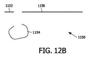
図11は、ビデオライン1002を備えたビデオ画像1000を概略的に示す。画像1000の各々のビデオライン1002のためのデータ1350は、図14に示されるように、ビデオストリーム1300中に含まれることができる。伝統的に、各々のライン1002は、ディスプレイのピクセルに直接対応する真直なラインである。以下に記載する実施の形態において、これらのラインは、非常に柔軟な様式で三次元情報を含むように拡張される。図12Aは、対象1102及びバックグラウンド1104を含む三次元シーンの断面1100の平面図を示す。生成されるべき信号は、好ましくは、矢印1106の方向に近い観察方向からのシーンの画像をレンダリングするための情報を含む。視点は、シーンから離れたある距離であることができ、図示されない。断面1100は、レンダリングプロセスの間、水平ビデオライン1102において見えるようになる可能性があるものに対応する。
FIG. 11 schematically shows a
システム100は、断面1100において見える対象の輪郭の少なくとも一部を生成するための輪郭生成器102を含む。そのような輪郭生成器は、従来技術において周知の態様で、例えば、depth-from-motionアルゴリズムを用いて、又は、シーンを記録するために複数のカメラを用いて深さ計算技術を適用することによって、実現されることができる。そのようなアルゴリズムは、完全な輪郭を再構成することができず、特に対象1102の背面1108は、いずれの画像においても見える可能性はなく、そのような場合、輪郭情報のこの部分は利用可能ではない。さらに、シーンの他の部分は、その前の他の対象のために遮蔽される場合がある。より多くのカメラ位置がシーンを記録するために用いられる場合、更なる輪郭情報が利用可能になる可能性がある。図12Bの輪郭1154は、システムに対して利用可能である可能性がある輪郭1150の例を示す。例えば、対象1102の輪郭の一部1154のみが、信号中に含めるために利用可能である。輪郭生成器102の代わりに、どこか他の所から輪郭生成器102によって生成された情報を受け取るための入力が設けられることができる。
The
システム100は、ビューからの三次元シーンの表現の少なくとも一部を定めるストライプのシーケンスを生成するためのシーケンス生成器104をさらに有する。ここで各々のストライプは、矩形領域の色、深さ及び位置を定めるデータ要素を含む画像情報の矩形領域を表す。このラインに基づく実施の形態において、矩形領域は、1データ要素の高さを持つとみなされる。輪郭上のサンプルポイントは、それらに、テュープルとして構成されることができる色、深さ及び位置のようなさまざまなデータ要素を関連付ける。図13に示される全てのサンプルポイントは、特定のビューに対してレンダリングされるビデオライン1002に寄与することができる。
The
ほとんどの現在のマルチビューディスプレイは複数のビューをレンダリングし、各々のビューの観察方向は、それぞれ水平方向のみにおいて異なる。結果として、画像のレンダリングは、ラインに基づく様式で一般に実行されることができる。結果的に、ビデオライン1002は、好ましくは水平ビデオラインである。しかしながら、本発明は、垂直方向に向くビデオラインにも適用されることができる。
Most current multi-view displays render multiple views, and the viewing direction of each view is different only in the horizontal direction. As a result, image rendering can generally be performed in a line-based manner. As a result,
これらのサンプルポイント1202は、シーン中の対象の輪郭1102の複数の区域から選択されることができる。サンプルポイントに関連付けられたデータ要素は、対応する輪郭点における対象輪郭の色に対応する、例えば赤、緑及び青(RGB)成分又は当業者に知られている他のフォーマットで表現された色を示すことができる。より柔軟なソリューションが望ましい場合には、例えば、バイナリ又は多値データ要素であることができ、したがって透明又は半透明な対象のエンコーディングを可能にする透明度データ要素のような、さらなる情報の追加を許容することが可能である。
These
データ要素は、深さ1208を示すこともできる。そのような深さは、1208で矢印によって示される方向における座標として表現されることができ、すなわち、視点に対する距離に関する情報を提供する。深さは、従来技術において周知であるように、視差値として表現されることもできる。表現される深さは、前に述べられた観察方向1106に対応する特定の一次ビューに対応する。
観察方向1106は、ここでは例えば、視点及びバックグラウンド1104の中心を通るラインに平行なラインの方向に関連する。カメラ位置がシーンの近くである場合、深さ座標は、バックグラウンド上へのシーンの投射による発散方向に対応することができる。データ要素は、さらに、矢印1210によって示される方向のビデオライン位置1210を示すことができる。このビデオライン位置1210は、一次ビューによる、ビデオ画像1000のビデオライン1002中の表示位置を示す。
The data element can also indicate a
The
特に、不規則に形成された形状を扱う場合、全てのサンプルポイントに関連した位置及び深さデータ要素を明示的に符号化することが重要である。このようにして、輪郭に対するサンプルポイントの任意の分布を符号化することが可能である。例えば、データ要素は、輪郭表面上において等距離で選択されるサンプルポイントに関連することができ、あるいは、特定の対象輪郭法線に関して等距離で選択されることができる。別の態様では、例えば多角形上の等距離のサンプルグリッドを用いる場合、より規則的なポリゴン構造を符号化するときに、より効率的な位置符号化が採用されることができる。 In particular, when dealing with irregularly formed shapes, it is important to explicitly encode the position and depth data elements associated with all sample points. In this way, it is possible to encode an arbitrary distribution of sample points relative to the contour. For example, the data elements can be associated with sample points that are selected equidistantly on the contour surface, or can be selected equidistant with respect to a particular target contour normal. In another aspect, more efficient position encoding can be employed when encoding a more regular polygon structure, for example when using equidistant sample grids on a polygon.
シーケンス生成器104は、輪郭ライン1150に沿った連続するポイントを選択する。例えば、ビデオラインが水平ラインである場合、セレクタ104は左から右に連続するポイントを選択することができる。あるいは、ポイントは、右から左に選択されることができる。セレクタ104は、バックグラウンドの左端の部分1152から始動することができ、そしてバックグラウンドの前の対象のために情報が存在しなくなるまで、右へと動作する。それから、セレクタ104は、対象の輪郭1154に関して継続することができる。セレクタは、輪郭1154の左端の端点にて始動することができ、右端の端点に達するまで輪郭1154に沿ってずっと動作し、そしてそこから、この場合にはバックグラウンドの残りの部分1156である次の対象に関して継続する。
The
シーケンス生成器104は、1204の近くのサンプルポイントのデータ要素、すなわち、一次ビュー中の少なくとも1つの対象1102の側面領域の一部である区域から選択されるサンプルポイントの連続するデータ要素を含む第1サブシーケンスを、ストライプのシーケンス中に包含することが可能である。シーケンス生成器104はさらに、1206の近くのサンプルポイントのデータ要素、すなわち、一次ビュー中の少なくとも1つの対象の前面領域の一部である区域から選択されるサンプルポイントの連続するデータ要素を含む第2サブシーケンスを包含することが可能である。第1サブシーケンス1204の2つの連続するサンプルポイントのビデオライン位置の間の差は、第2サブシーケンス1206の2つの連続するサンプルポイントのビデオライン位置の間の差よりも小さい。このように、特定のシーケンス部分は、レンダリングされる出力の画質を改善するためにより高いサンプル周波数で、あるいは表示サイズのためにより低いサンプル周波数でサンプリングされたデータ要素を用いて表される。
The
シーケンス生成器104は、異なるストライプ間の接続を示すためにストライプ内に1つ以上の透明なデータ要素1212を示すテュープルを包含するように配置される。これらの透明なサンプル1212は、ディスプレイシステム150においてストライプのシーケンスを効率的にレンダリングする際の助けとなる。例えば、輪郭が透明か否かを示す特別なデータ要素が、ストライプ中に又はデータ要素のテュープル中に包含され、あるいは、特定の色の値又は色の範囲が、「透明」を示すために予約される。信号がその後不可逆圧縮を受ける場合、範囲の使用は特に有益である。システム100は、ストライプ1350のシーケンス中に含まれるデータ要素から成るビデオ信号を生成するための信号生成器106をさらに有する。ストライプのシーケンスが適切に符号化される限り、この信号生成器は任意の態様で実現されることができる。デジタル信号エンコーディング方法(例えばMPEG規格)が使用されることができる。ストレージ信号及び伝送信号を含む他のアナログ及びデジタル信号が生成されることができ、この説明からみて当業者の圏内である。例えば、ストライプのデジタルシーケンスは、磁気ディスク又はDVD上のファイル中に単に記憶されることができる。信号は、ディスプレイシステム150によって受信されるように、例えば衛星又はケーブルTVを介して放送されることもでき、あるいは、インターネットを介して送信されるか、DVI又はHDMIのようなインタフェース上で送信されることができる。
The
ストライプの複数のそれぞれのシーケンスが作成されて、複数のそれぞれのビデオライン1002の信号中に組み込まれることができる。これは、完全な三次元ビデオ画像1000を符号化することを可能にする。
A plurality of respective sequences of stripes can be created and incorporated into the signals of the plurality of
いくつかの手段102、104及び106は、例えばランダムアクセスメモリ110を介してそれらの中間結果を通信することができる。他のアーキテクチャデザインも可能である。
Some means 102, 104 and 106 can communicate their intermediate results via a
システム100は、さらに、一次ビューにおいて遮蔽される区域からの及び/又は対象の背面領域のサンプルを包含することを可能にする。
The
図14は、概略的にいくつかのデータストリームから成るトランスポートストリームを示す。各々の水平のロウは、トランスポートストリーム中のデータストリームを表す。そのようなトランスポートストリームは、信号生成器106によって生成されることができる。別の態様では、信号生成器106は単に、多重化装置(図示せず)によってトランスポートストリーム中に包含するためのデータストリームを提供する。ブロック1350は、ビデオラインに対応するストライプのシーケンスを表す。ライン上のいくつかのブロックは、画像の異なるビデオラインのためのストライプのシーケンスに対応する。実際には、これらのデータブロックは、より大きいデータチャンク(図示せず)中にこれらのブロックの多くを結合する場合がある圧縮方法を受ける可能性がある。信号生成器106によって生成されるトランスポートストリームは、ストライプの少なくとも第1サブセットの色を示すデータ要素を含む第1データストリーム1302を有することができる。さらに、第2データストリーム1304は、ストライプの少なくとも第1サブセットの深さを示すデータ要素を有することができる。結果的に、ストライプのそれぞれのデータ要素は、信号中で別々に送信されることができる。これは、深さ及び/又は水平位置のような追加の情報は、それらが色情報とは個別の補助データストリーム中に包含される場合、レガシー表示装置によって無視されることができるので、圧縮結果を改善することができ、下位互換性を提供するのを助ける。さらに、色及び/又は深さが従来技術において周知の方法を用いて符号化されることができ、二次元ビデオ符号化における開発を活用して、既存のビデオ符号器及び復号器の再利用を可能にする。
FIG. 14 schematically shows a transport stream consisting of several data streams. Each horizontal row represents a data stream in the transport stream. Such a transport stream can be generated by the
圧縮率をさらに改善するために、信号生成器106は、パディングデータ要素を挿入することによって、ストライプの第1シーケンス中のデータ要素をストライプの第2シーケンス中のそれらに位置合わせするように配置されることができる(両方のシーケンスは少なくとも1つの対象のある部分に関連する)。例えば、ストライプの第1シーケンスが第1ビデオラインに関連し、そしてストライプの第2シーケンスが隣り合うビデオラインに関連する状況を考える。この場合には、ストライプの第1シーケンス中のデータ要素番号Nが、ストライプの第2シーケンス中のデータ要素番号Nと同じ水平位置を持つように、シーケンスが水平方向に位置合わせされることができる。
To further improve the compression ratio, the
ストライプのシーケンスがスキャン方向に沿って符号化される場合、ストライプのシーケンスは、データストリーム中の空間的に隣り合うデータ要素が、スキャン方向に対して垂直な方向に空間的に近接するデータ要素に位置合わせされるように、シーケンス生成器によってデータストリーム中に符号化されることができる。 When a sequence of stripes is encoded along the scan direction, the sequence of stripes is such that spatially adjacent data elements in the data stream are in close proximity to data elements in a direction perpendicular to the scan direction. It can be encoded into the data stream by the sequence generator to be aligned.
信号生成器106は、ストライプの少なくとも第1サブセットの位置を有する第3データストリーム1306をさらに生成することができる。これらの位置値は、(例えばビデオ画像の左側に対応する)固定の基準位置に対する位置値として符号化されることができる。好ましくは、連続するサンプルの位置は、連続するサンプルのビデオライン位置間のδ(差分)として表現される。後者の場合、値は、ランレングス符号化(周知の無損失圧縮技術)を用いて効率的に圧縮されることができる。しかしながら、圧縮はオプションであり、処理要求が帯域幅より重大である状況では、圧縮は必要ない場合がある。例えば、DVI又はHDMIのような表示インタフェースを用いる場合、圧縮は必要ない場合がある。そのような場合、δ値すなわち固定の基準点に対する値は、例えば色チャネルのうちの2つ(例えば緑及び青チャネル)において、圧縮されていない形態で符号化されることができ、深さは、第3の色チャネル(例えば赤チャネル)において符号化されることができる。
The
図15は、下位互換性が提供される他の実施の形態を示す。この目的のために、標準的な二次元ビデオフレームが、図10Cを参照して説明される状況に類似した形で、第1ストリーム1402中に符号化される。この第1ストリーム1402は、レガシー二次元ディスプレイと互換性がある。対応する深さ値は、第2ストリーム1404中に記憶される。第1ストリーム1402及び第2ストリーム1404の組み合わせは、画像及び深さビデオデータをレンダリングすることができるレガシー三次元ディスプレイとの互換性を持つことができる。レガシー二次元画像のための(図14の第3ストリーム1306中にあるような)水平位置は、それらは標準的なビデオフレームではアプリオリに既知であるので、省略されることができる。しかしながら、ストリーム1402及び1404に加えて、画像及び深さストリーム1402及び1404中に存在しないストライプのシーケンスの部分は、一つ以上の追加のストリーム中に包含される。言い換えると、少なくともストライプのシーケンスの第2サブセットによって表される情報は、ストリームの異なるセットにおいて符号化され、第1サブセット及び第2サブセットは分離している。ストリームは、部分的に重なり合うポイントに関連することができ、例えば、特定の輪郭区域が不十分な分解能でストリーム1402及び1404中に表される場合(例えば、観察方向の角度に近いある角度における平面に関連する画像情報)、追加のストリームは、その特定の輪郭区域のより高い分解能バージョンを提供することができる。例えば、更なるストリーム1408は、ストライプのシーケンスの少なくとも第2サブセットの色を有し、更なるストリーム1410は、ストライプのシーケンスの少なくとも第2サブセットの深さを有し、そして、更なるストリーム1412は、ストライプのシーケンスの少なくとも第2サブセットの水平位置を有する。
FIG. 15 illustrates another embodiment in which backward compatibility is provided. For this purpose, a standard 2D video frame is encoded in the
さらに、1つ以上の下位互換性を持つストリーム中に包含するために情報の他の部分を抽出することも可能である。例えば、複数の画像及び深さレイヤ又は他のレイヤード深さ画像(LDI)表示が、下位互換性を持つストリーム中に包含されることができる。下位互換性を持つストリーム中に包含されない残りの情報及び/又は不十分な分解能で下位互換性を持つストリーム中に包含される残りの情報は、別々に包含されることができる。 In addition, other parts of the information can be extracted for inclusion in one or more backward compatible streams. For example, multiple images and depth layers or other layered depth image (LDI) displays can be included in a backward compatible stream. The remaining information not included in the backward compatible stream and / or the remaining information included in the backward compatible stream with insufficient resolution can be included separately.
実施の形態は、一次ビューからの三次元シーンを表す信号1300を含み、この信号は、ビューからの三次元シーンの表現の少なくとも一部を定めるストライプのシーケンス1350を有する。各々のストライプは次に、色、深さ1208及び位置1210を定めるデータ要素を含む画像情報の矩形領域を表し、各々のストライプの色及び深さデータ要素は、シーン中の少なくとも1つの対象の表面輪郭情報1102から導き出される。位置データの要素は、ビュー内の少なくとも1つの対象の表面輪郭情報の位置1202から導き出され、ストライプのシーケンスのうちの少なくとも1つのストライプ1204は、シーン中の少なくとも1つの対象の遮蔽された領域又は側面領域から選択される少なくとも1つの対象の表面輪郭情報を表す。
Embodiments include a
ストライプのシーケンスは、一次ビュー中の少なくとも1つの対象の遮蔽された領域又は側面領域の一部である区域から選択される連続するポイントと関連したデータ要素の第1ストライプ1204、及び、一次ビュー中の少なくとも1つの対象の前面領域の一部である区域から選択される連続するデータ要素の第2ストライプ1206を有する。さらに、第1サブシーケンスの2つの連続する位置データ要素の水平位置間の第1差分は、第2サブシーケンスの2つの連続する位置要素の水平位置間の第2差分より小さい場合がある。
The sequence of stripes includes a
図1を参照して、ディスプレイシステム150は、述べられたようなストライプのシーケンスを表す信号を受け取るための入力152を有する。ディスプレイシステム150は、例えば、記憶媒体から又はネットワーク接続を介してそれを読み出すことによって、この信号を受け取ることができる。
Referring to FIG. 1, display system 150 has an
ディスプレイシステム150は、さらに、ストライプのシーケンスを用いて立体視に対応する複数の画像を生成するための画像生成器154を有する。立体視は、異なる観察方向を持ち、すなわち、それらは同じ三次元シーンの異なるビューに対応する。ビューは、好ましくは水平方向に分配され、又は、少なくとも水平方向に沿っている。複数の画像のうちの1つの画像は、以下の通りに生成されることができる。最初に、位置及び深さデータ要素が、生成されるべき画像の観察方向及び視点に対応するビデオライン位置及び深さに変換される。次に、画像はこれらの変換された値を用いてレンダリングされ、ここで、任意の水平位置に対して、視点に最も近い位置を示す深さ値のみが考慮されることを必要とする。要するに、テュープルのシーケンスは、ラインに基づくストライプの場合には1つ以上の三次元ポリラインを表し、マルチラインに基づくストライプの場合にはポリゴンを表す。これらのポリラインは、従来技術において周知であるように、zバッファリングを用いてレンダリングされることができる。例えば、ストライプのシーケンスと関連したデータ要素は、zバッファリングを用いて個別にレンダリングされることができる。データ要素のレンダリングの厳密な様式は本発明を制限しない。
The display system 150 further includes an
ディスプレイシステムは、複数の画像を表示するためのディスプレイ156を有することができる。例えば、ディスプレイ156は、自動立体視傾斜レンチキュラディスプレイであることができる。いくつかの画像は、インタリーブされた態様でそのようなディスプレイにレンダリングされることができる。別の態様では、2つの画像はタイムシーケンシャルに表示されることができ、そして、シャッタ眼鏡が、人による適切な三次元画像認識のために用いられることができる。立体表示モードを含む他の種類の表示モードが当業者に知られている。複数の画像が、三次元ディスプレイ又は二次元ディスプレイ上に次々と表示されることもでき、それは、回転効果を生成することができる。他の画像を表示する態様(例えばシーンを通してのインタラクティブな仮想的ナビゲーション)も可能である。
The display system can include a
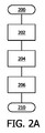
図2Aは、ビデオ信号を生成する方法における処理ステップを示す。ステップ200において、例えば新たなビデオフレームが処理されるべきときに、プロセスが開始される。ステップ202において、説明されるように、バックグラウンドを含むシーン中の対象の輪郭ラインが作成される。プロセスの中で明示的にこのステップを実行する代わりに、ステップ202の結果は、プロセスの入力として提供されることができる。
FIG. 2A shows processing steps in a method for generating a video signal. In
ステップ204において、ストライプのシーケンス1350が生成され、一次ビューからの三次元シーンの表示の少なくとも一部を定めて、各々のストライプは、色、深さ1208及び位置1210を定めるデータ要素を含む画像情報の矩形領域を表す。各々のストライプの色及び深さデータ要素は、シーン中の少なくとも1つの対象の表面輪郭情報1102から導き出される。位置データ要素は、一次ビュー1202中の少なくとも1つの対象の表面輪郭情報の位置から導き出される。さらに、ステップ204は、一次ビュー中の少なくとも1つの対象の側面領域の一部である区域から選択される連続するポイントのデータ要素を含む第1ストライプ1204をストライプのシーケンス中に包含することを含むことができる。連続するポイントのデータ要素を含む第2ストライプ1206は、一次ビュー中の少なくとも1つの対象の前面領域の一部である区域から選択されることができる。第1サブシーケンスの2つの連続する位置データ要素の水平位置間の第1差分は、第2サブシーケンスの2つの連続する位置データ要素の水平位置間の第2差分より小さい場合がある。
In
ステップ202及び204は、画像中の複数のビデオラインに対して繰り返されることができる。ステップ206において、結果として生じるサンプルのシーケンスを含むビデオ信号が生成される。ステップ210においてプロセスは終了する。先に示されたように、本方法は、ストライプのラインに基づくシーケンス及びストライプのマルチラインに基づくシーケンスにも同様に適用されることができる。ステップ202は、以下のように実行されることができる。複数の異なるビューから観察される少なくとも1つの対象の複数の画像が受け取られる。深さ情報は、複数の画像のピクセルのために確立されるか、又は、追加の入力(例えば範囲検出器を用いて決定された深さ値)として提供されることができる。二次ビューのピクセルは一次ビューに対してゆがめられ、少なくとも1つの対象の一次ビューによる深さ及び水平位置を示す情報が、ピクセルに対して得られる。このように輪郭情報が得られる。
図2Bは、ディスプレイ上に画像をレンダリングする方法を示す。ステップ250において、例えば新たなビデオフレームが表示のために作成されることを必要とするので、プロセスが開始される。ステップ252において、説明されたように、ストライプのシーケンス(1350)から成る信号が受け取られる。ステップ254において、複数の画像が、ストライプのシーケンスを用いて立体視に対応して生成される。ステップ256において、説明されたように、複数の画像が表示される。
FIG. 2B shows a method for rendering an image on a display. In
本明細書において説明されるプロセス及びシステムは、部分的に又は完全にソフトウェアで実現されることができる。 The processes and systems described herein can be implemented partially or fully in software.
図3は、バックグラウンド面5の面に3つの対象1, 2及び3を有するシーンの断面平面図を示す。矢印310の方向に対象1, 2, 3及びバックグラウンド面5を見る場合、画像及び深さフォーマットは、ピクセル毎の色及び深さとして、図4に401-405で示される情報を記憶する。別のビューがこの表現から生成されることができるが、異なる視角で、例えば矢印320によって示される方向でシーンを観察する場合、この画像及び深さ表現は、実際に対象を「見まわす」ため、及び、見えるようになるもの、すなわち遮蔽されないもの(例えば、元の位置より左の位置から見るときに見えるようになる対象1の前面の右の部分、又は、対象2と3との間の右から見るときに見える可能性があるバックグラウンドの部分)を見るために必要な情報を含まない。
FIG. 3 shows a cross-sectional plan view of a scene with three
図5は、画像及び深さの多重レイヤを用いることによるこの問題に対する部分的なソリューションを示す。例えば、画像及び深さの2つのレイヤが用いられることができる。図5は、本実施例のための第2レイヤ中に記憶されることができる追加の情報を501-505で示す。ここでは対象1及び3の完全な前向きの面が記憶されることができるが、完全なバックグラウンドをさらに記憶するために3つのレイヤが必要とされる。さらに、中央のビューに対して固定の水平間隔を用いる表現を用いて対象(例えば対象1及び3)の側面を定めることは難しい。さらに、対象の後ろ向きの面は、この表現と共に記憶されない。複数のビューからの画像及び深さを記憶することは1つのソリューションであるかもしれないが、深さ信号の圧縮中にそれらの関係を完全なままに維持することは難しく、複雑な計算を必要とし、さらに、多くのビューが用いられるか、又は複数のレイヤが複数ビューのために提供されない限り、そのような表現によって透明度をサポートすることは難しく、それは、多くのレイヤ、ひいては多くの記憶空間を必要とする場合がある。
FIG. 5 shows a partial solution to this problem by using multiple layers of images and depth. For example, two layers of image and depth can be used. FIG. 5 shows additional information 501-505 that can be stored in the second layer for this example. Here the complete forward faces of
図6は、一種のドレープ600のような画像データを構成する態様を示す。そのようなドレープ600によって、シーンの輪郭記述は、効率的かつスケーラブルな態様で提供されることができる。そのようなドレープ600は、比喩的には、シーンの対象1-3及びバックグラウンド5に掛けられるシートのように振る舞う。図6は、ドレープ600がシーンにゆるく掛けられる場合の構成を示す。
FIG. 6 shows an aspect of constructing image data such as a kind of
ドレープ600は、シーンの対象の表面に沿った輪郭ラインを記述する。好ましくは、そのような輪郭ラインは、完全にシーンの断面の中である。ドレープ600は、対象の正面602である輪郭ラインの部分を含むだけでなく、対象1の左側面601及び対象2の左側面、並びに、対象3の右側面603及び対象2の右側面も含む。結果的に、画像及び深さフォーマットと比較して、より多くの遮蔽データが取り込まれる。ドレープ600のいくつかの部分は画像データを含む。この例は、部分601、602及び603である。ドレープ600の他の部分は透明である。透明な部分の例は、部分610, 611, 612及び613である。そのような透明な部分は、多くの記憶空間を必要としない。例えば、そのような部分は、全体的にスキップされることができる。好ましくは、ドレープの一部が透明であることを示す指示が、信号中に挿入される。別の態様では、ドレープの連続する断片間の距離が予め定められた閾値を上回る場合、ドレープの連続する断片間の部分は透明に設定される。
The
図7は、より多くの遮蔽データがドレープ表現において取り込まれることができることを示す。比喩的に、ドレープは、シーンの対象のまわりにより密着して合わせられることができる。図7において、ドレープ700は、対象の全輪郭が横断される程に締付けられて、立体視を生成する際の最大のフレキシビリティを提供する。図6及び図7の状況の間の中間の締付け量も可能である。
FIG. 7 shows that more occlusion data can be captured in the drape representation. Figuratively, the drape can be matched more closely around the subject of the scene. In FIG. 7, the
締付け量の次に、ドレープに沿って情報が記憶される分解能も、情報の量と記憶/伝送容量とのバランスをとるために変化することができる。先に述べられた「透明な」部分はこの極端な例であるが、例えば、より低い分解能で対象の側面(そして特に対象の背面)を符号化することを選ぶこともできる。その場合、ドレープは等距離の又は非等距離のポイントと関連した一連のデータ要素から成ることができる。これらのデータの要素は、色あるいは透明度に関する情報をも含むことができる。オプションとして、ビュー方向依存性効果を取り込むために追加の情報が含まれることができ、例えば、任意の他の関連する情報と同様に、双方向リフレクタンス分布データが、さらに含まれることができる。サンプルは、関連した座標を持つことができる(図に示されるドレープのx及びz、並びに、全三次元画像が表される場合、各々のラインのための系列)。異なる方法が、これらの系列を記憶するために用いられることができる。特に、可逆圧縮が用いられる場合、連鎖符号が用いられる。 Next to the amount of tightening, the resolution at which information is stored along the drape can also be varied to balance the amount of information and the storage / transmission capacity. The “transparent” part mentioned above is an extreme example of this, but for example, one could choose to encode the side of the object (and especially the back of the object) with a lower resolution. In that case, the drape may consist of a series of data elements associated with equidistant or non-equal distance points. These data elements can also contain information about color or transparency. Optionally, additional information can be included to capture view direction dependent effects, for example, bi-directional reflectance distribution data can be further included, as well as any other relevant information. A sample can have associated coordinates (drape x and z shown in the figure, and a sequence for each line if a full 3D image is represented). Different methods can be used to store these sequences. In particular, when lossless compression is used, a chain code is used.
後続の水平ドレープラインの垂直結合を保持することが可能である。これは、良好な圧縮性能を達成することを可能にする。例えば、通常の画像及び深さ表現が別に抽出又は記憶されることができ、(画像及び深さサンプルへ再挿入されることができる)ドレープの追加の断片が追加のデータとして記憶されることができる。これは、現在の画像及び深さフォーマットとの下位互換性を保証して、オプションとして完全なドレープデータを追加する。さらに、通常の画像及び深さ表現は、高性能の圧縮技術を用いて圧縮されることができる。そして、追加のデータ中の残りの断片は、最適な圧縮のために垂直結合が最大にされるように、配置されることができる。ドレープラインが垂直ビデオラインに対応する場合、水平結合は同様に保持されることができる。 It is possible to preserve the vertical coupling of subsequent horizontal drape lines. This makes it possible to achieve good compression performance. For example, normal images and depth representations can be extracted or stored separately, and additional pieces of drape (which can be reinserted into the images and depth samples) can be stored as additional data. it can. This ensures backward compatibility with current image and depth formats and optionally adds complete drape data. Furthermore, normal images and depth representations can be compressed using high performance compression techniques. The remaining fragments in the additional data can then be arranged so that vertical coupling is maximized for optimal compression. If the drape line corresponds to a vertical video line, horizontal coupling can be maintained as well.
ドレープ表現は、異なる位置からシーンを見るいくつかのカメラの画像(及び場合により深さ)から構成されることができ、又は、(仮想)シーンによるスライシングによって得られるボクセル表現から、例えば導き出されることができる。ドレープからビューをレンダリングすることは、適切な遮蔽及び非遮蔽の取扱いを伴う深さ依存性シフトのプロセスによって実現されることができる。 The drape representation can consist of several camera images (and possibly depth) looking at the scene from different positions, or can be derived eg from a voxel representation obtained by slicing with a (virtual) scene. Can do. Rendering a view from a drape can be accomplished by a process of depth dependent shifting with appropriate occlusion and non-occlusion handling.
コンピュータグラフィックの分野において、例えば、"Relief texture mapping" by M.M. Oliveira et al., in Proceedings of the 27th annual conference on Computer graphics and interactive techniques, pages 359-368, 2000, ISBN 1-58113-208-5に記載されているように、境界表現が知られている。これらのコンピュータグラフィックス表現は、現実には通常非常に幾何学的であり(例えばメッシュに基づく)、一方、ドレープは、非常に適切に圧縮されることができるビデオ信号として色だけでなく深さも表されることができるビデオのような表現に用いられることができる。 In the field of computer graphics, for example, "Relief texture mapping" by MM Oliveira et al., In Proceedings of the 27th annual conference on Computer graphics and interactive techniques, pages 359-368, 2000, ISBN 1-58113-208-5 As described, the boundary representation is known. These computer graphics representations are usually very geometric in reality (e.g. based on mesh), while drapes are not only color but also depth as video signals that can be very well compressed. It can be used for video-like expressions that can be represented.
本明細書において記載される技術を用いて垂直非遮蔽情報を符号化することも可能である。例えば、サンプルの1つ以上のシーケンスは、それと関連した水平位置の代わりに垂直位置を持つことができる。これらの「垂直ドレープライン」は、「水平ドレープライン」の代わりに、又はそれに加えて、用いられることができる。別の態様では、サンプルの連続するシーケンス間の垂直間隔は、対象の上及び/又は下の端を視覚化することを可能にするために、可変にされることができる。 It is also possible to encode vertical unshielded information using the techniques described herein. For example, one or more sequences of samples can have a vertical position instead of a horizontal position associated with it. These “vertical drape lines” can be used instead of or in addition to “horizontal drape lines”. In another aspect, the vertical spacing between successive sequences of samples can be varied to allow visualization of the top and / or bottom edges of the subject.
「ドレープ」は、ストライプのシーケンスで記述されることができる。これらのストライプは、色の値、水平位置の値(例えば一次ビューのライン上のピクセル数)、深さ値若しくは視差値、及び/又は、透明度インジケータ若しくは値を有することができる。完全に透明な部分に対して色は必要とされないか、又は特定の色の値が「透明」を示すために予約されることができることは明らかである。前面が観察方向に略垂直な場合の側面は、(略又は正確に)同じ位置p、異なるd及び適切な色の値を持つ連続的なテュープルを用いて記述される。互いの前にある対象は、ドレープの透明な部分によって接続されることができる。「ゆるいドレープ」を用いる場合、対象の前面及び側面のみがドレープにおいて記述される。「密着したドレープ」を用いる場合、対象の裏面もドレープにおいて記述される。多くの場合に、いくつかの側面及び背面情報が存在するが、全ての情報というわけではない。ドレープは、利用可能な任意の情報を収容するために用いられることができる。利用可能でない又は受信側において必要ない情報のための記憶空間を浪費する必要はない。さらに、冗長なデータを記憶する必要はない。複数のレイヤを用いるビデオ符号化において、圧縮後でさえも全てのレイヤを満たすために利用可能な十分な情報がない場合、多少の記憶空間が無駄になる場合がある。 A “drape” can be described by a sequence of stripes. These stripes can have color values, horizontal position values (eg, the number of pixels on the primary view line), depth values or parallax values, and / or transparency indicators or values. Obviously, no color is required for completely transparent parts, or a specific color value can be reserved to indicate "transparent". The side surface when the front surface is substantially perpendicular to the viewing direction is described using continuous tuples with the same position p, different d and appropriate color values (substantially or exactly). Objects in front of each other can be connected by a transparent portion of the drape. When using “loose drape”, only the front and sides of the object are described in the drape. When using “close drape”, the back side of the object is also described in the drape. In many cases, some side and back information exists, but not all information. A drape can be used to contain any available information. There is no need to waste storage space for information that is not available or not needed at the receiver. Furthermore, there is no need to store redundant data. In video coding using multiple layers, some storage space may be wasted if there is not enough information available to fill all layers even after compression.
例えば3つの隣り合うカメラ(左、中央及び右のカメラ)によって撮られる同じシーンの3つの画像(左、中央及び右の画像)を用いることによって、3つの画像の情報を単一のドレープに統合することが可能である。第一に、深さマップが全3つの画像のために再構成される。例えばカメラキャリブレーションを伴う立体視的計算が用いられることができる。そのような計算は、従来技術において周知である。次に、右及び左の画像が、中央の画像のジオメトリーに対してゆがめられる。ゆがめられた左の画像、ゆがめられた右の画像及び中央の画像中に現れる表面は、重なり合うか又は隣り合う表面領域を検出することによって、一緒につぎ合わせられることができる。次に、ドレープラインは、これらの(ゆがめられた)画像点から、サンプリング又は選択することによって構成されることができる。 For example, by using three images (left, center and right images) of the same scene taken by three adjacent cameras (left, center and right cameras), the information of the three images is integrated into a single drape. Is possible. First, the depth map is reconstructed for all three images. For example, a stereoscopic calculation with camera calibration can be used. Such calculations are well known in the prior art. The right and left images are then distorted with respect to the geometry of the center image. Surfaces appearing in the distorted left image, the distorted right image, and the center image can be joined together by detecting overlapping or adjacent surface regions. A drape line can then be constructed by sampling or selecting from these (distorted) image points.
垂直方向の一貫性を維持するために、透明なサンプルを挿入することが可能である。これは、既知のビデオ圧縮技術を用いる場合に達成される圧縮比を改善する。 In order to maintain vertical consistency, it is possible to insert a transparent sample. This improves the compression ratio achieved when using known video compression techniques.
ドレープラインのレンダリングは、zバッファリングを用いた三次元ポリラインのレンダリングと同様の態様で実行されることができる。 The rendering of the drape line can be performed in a manner similar to the rendering of a three-dimensional polyline using z-buffering.
ドレープラインを表すサンプルのシーケンスは、複数の画像中に記憶されることができる。第1画像は、色情報を有することができる。3つの別々の画像として各々の成分(例えばR, G及びB又はY, U及びV)を符号化することも可能である。従来技術では周知のように、U及びVをサブサンプリングすることによってより良好に圧縮されることができる例えばYUV色空間に色を変換することも可能である。第2画像は、深さ情報を有することができる。この深さ情報は、例えば、座標によって又は視差情報によって、符号化されることができる。第3画像は、例えば全ピクセル中で、又は代わりに、サブピクセル精度(例えば浮動小数点値)を可能にする指標を用いて表現される、水平座標:ビデオライン位置を有することができる。これらの画像は、標準的なビデオ圧縮を用いてさらに圧縮されることができる。好ましくは、x座標を含む画像はδで表現されることができ、連続するサンプルのx座標間の差分が、x座標の絶対値の代わりに記憶されることができる。これは、効率的なランレングス符号化圧縮を実行することを可能にする。これらの画像は、個別のデータストリーム中に記憶されることができる。 A sequence of samples representing a drape line can be stored in multiple images. The first image can have color information. It is also possible to encode each component (eg R, G and B or Y, U and V) as three separate images. As is well known in the prior art, it is also possible to convert colors into eg a YUV color space which can be better compressed by subsampling U and V. The second image can have depth information. This depth information can be encoded, for example, by coordinates or by parallax information. The third image may have a horizontal coordinate: video line position that is represented, for example, in all pixels or alternatively with an index that allows sub-pixel accuracy (eg, floating point value). These images can be further compressed using standard video compression. Preferably, the image including the x coordinate can be represented by δ, and the difference between the x coordinates of successive samples can be stored instead of the absolute value of the x coordinate. This makes it possible to perform efficient run length coding compression. These images can be stored in separate data streams.
好ましくは、従来のビデオストリームとして別々に記憶又は送信されるように、オプションの深さ情報を有する通常の二次元画像を抽出することによって、下位互換性が提供される。深さ画像は、補助ストリームとして追加されることができる。サンプルのシーケンスの残りの部分は、1つ以上の個別のストリーム中に記憶されることができる。 Preferably, backward compatibility is provided by extracting a normal two-dimensional image with optional depth information to be stored or transmitted separately as a conventional video stream. The depth image can be added as an auxiliary stream. The remaining portion of the sequence of samples can be stored in one or more individual streams.
図8は、立方体801及びバックグラウンド802を含むシーンを示す。このシーンは、3つのカメラ位置810、811及び812を用いて取り込まれる。図8は、特に、左のカメラ810を用いて取り込まれるものを示す。例えば、この左のカメラは、輪郭区域A、B、C、D、E及びIを取り込むが、輪郭区域F、G及びHは取り込まない。
FIG. 8 shows a scene that includes a
カメラのうちの2台の画像データは、第3のカメラ位置の方に曲げられることができ、例えば、左端の及び右端の画像は、中央のカメラの方へと曲げられることができ、中央のカメラは、曲げられた画像のピクセルのx値を変更する。図8中の立方物体の側面の場合のように、いくつかのピクセルが同じx値(但し異なる深さ値)を持つことが起こり得る。特に左のカメラが中央のカメラのビューでは対象の背面である対象の部分を見る場合、そのような曲げられた画像のx値が非単調であることもあり得る。これらの側面及び背面部分は、本明細書に記載されているように、テュープルのシーケンス("ドレープ")中に効率的に記憶されることができる。そのような側面又は背面部分が記憶される分解能は、利用可能なビュー中の側面又は背面部分に割り当てられるピクセルの数によって決まることができる。 The image data of two of the cameras can be bent towards the third camera position, for example, the left and right edge images can be bent towards the center camera, The camera changes the x value of the pixel in the bent image. It can happen that several pixels have the same x value (but different depth values), as in the case of the side of the cubic object in FIG. The x value of such a bent image can be non-monotonic, especially when the left camera sees the part of the object that is the back of the object in the center camera view. These side and back portions can be efficiently stored during a tuple sequence ("drape"), as described herein. The resolution at which such side or back portions are stored can depend on the number of pixels assigned to the side or back portions in the available view.
図9は、ソフトウェアで本明細書に記載される方法及びシステムの一部を実現するための例示のハードウェアアーキテクチャを示す。他のアーキテクチャも用いられることができる。メモリ906は、命令を構成するコンピュータプログラムを記憶するために用いられる。これらの命令は、プロセッサ902によって読み出されて実行される。入力904は、例えばリモートコントロール又はコンピュータキーボードによって、ユーザのインタラクションを可能にするために提供される。これは、例えば、画像のシーケンスの処理を開始するために用いられることができる。入力はさらに、深さ知覚の量、生成する立体画像の数、又はビデオ信号中に含まれる遮蔽データの量及び分解能のような、設定可能なパラメータを設定するために用いられることができる。ディスプレイ912は、例えば、グラフィカルユーザインタフェースを提供することによってユーザフレンドリーな態様でインタラクション可能性を実現するために有用である。ディスプレイ912はさらに、入力画像、出力画像、及び、本明細書に記載された処理の中間結果を表示するために用いられることができる。画像データの交換は、ビデオネットワーク(例えばデジタル若しくはアナログ、地上波、衛星若しくはケーブル放送システム)又はインターネットに接続されることができる通信ポート908によって促進される。データ交換は、さらに、取外し可能なメディア910(例えば、DVDドライブ又はフラッシュドライブ)によって促進される。そのような画像データは、ローカルメモリ906中に記憶されることもできる。
FIG. 9 illustrates an example hardware architecture for implementing some of the methods and systems described herein in software. Other architectures can also be used. The
いうまでもなく、本発明はさらに、本発明を実現するために適応されたコンピュータプログラム、特にキャリア上の又はその中のコンピュータプログラムに及ぶ。プログラムは、ソースコード、オブジェクトコード、コード中間ソース及び部分的にコンパイルされた形態のオブジェクトコードの形、又は、本発明による方法の実施で使用するのに適した任意の他の形態であることができる。キャリアは、プログラムを運ぶことが可能な任意のエンティティ又は装置であることができる。例えば、キャリアは、ROM(例えばCD ROM若しくは半導体ROM)、又は磁気記録媒体(例えばフロッピーティスク若しくはハードディスク)のような記憶媒体を含むことができる。さらにキャリアは、伝播性キャリア(例えば電気又は光信号)であることができ、それらは、電気若しくは光ケーブルを介して又は無線若しくは他の手段によって伝達されることができる。プログラムがそのような信号で実施される場合、キャリアはそのようなケーブル又は他の装置若しくは手段によって構成されることができる。別の形態として、キャリアは、その中にプログラムが組み込まれる集積回路であることができ、この集積回路は、関連する方法を実行するように又はその実行に用いるために適応される。 Needless to say, the invention further extends to a computer program adapted to implement the invention, in particular a computer program on or in a carrier. The program may be in the form of source code, object code, code intermediate source and partially compiled object code, or any other form suitable for use in performing the method according to the invention. it can. A carrier can be any entity or device capable of carrying a program. For example, the carrier can include a storage medium such as a ROM (eg, CD ROM or semiconductor ROM), or a magnetic recording medium (eg, floppy disk or hard disk). Further, the carriers can be propagating carriers (eg, electrical or optical signals), which can be transmitted via electrical or optical cables or by radio or other means. If the program is implemented with such signals, the carrier can be constituted by such cables or other devices or means. Alternatively, the carrier can be an integrated circuit in which the program is embedded, and this integrated circuit is adapted to perform or use for performing the associated method.
上述の実施の形態は、本発明を制限ではなく説明するものであり、当業者は、添付の請求の範囲から逸脱することなく、多くの代わりの実施の形態を設計することができることに留意すべきである。請求の範囲において、括弧間に配置される任意の参照符号は、請求の範囲を制限するものとして解釈されてはならない。「有する」「含む」などの用語及びその活用形の使用は、請求の範囲中に挙げられた要素又はステップ以外の要素又はステップの存在を除外しない。単数で表現された要素は、そのような要素が複数存在することを除外しない。本発明は、いくつかの別個の要素から成るハードウェアによって、そして適切にプログラムされたコンピュータによって実現されることができる。いくつかの手段を列挙する装置の請求項において、これらの手段のいくつかは、ハードウェアの同じ1つのアイテムによって実施されることができる。単に特定の手段が相互に異なる従属請求項中に挙げられていることは、利益を得るためにこれらの手段の組み合わせが用いられることができないことを意味しない。 The above-described embodiments are intended to illustrate the present invention rather than to limit it, and one skilled in the art can design many alternative embodiments without departing from the scope of the appended claims. Should. In the claims, any reference signs placed between parentheses shall not be construed as limiting the claim. The use of terms such as “comprising”, “including” and their conjugations does not exclude the presence of elements or steps other than those listed in a claim. An element expressed in the singular does not exclude the presence of a plurality of such elements. The present invention can be realized by hardware consisting of several distinct elements and by a suitably programmed computer. In the device claim enumerating several means, several of these means can be embodied by one and the same item of hardware. The mere fact that certain measures are recited in mutually different dependent claims does not indicate that a combination of these measures cannot be used to benefit.
Claims (17)
前記一次ビューからの前記三次元シーンの表現の少なくとも一部を定めるストライプのシーケンスを生成するシーケンス生成器、及び
前記ストライプのシーケンスを含むビデオ信号を生成する信号生成器を有し、
各々のストライプは、矩形領域の色、深さ及び位置を定めるデータ要素を含む画像情報の前記矩形領域を表し、
各々のストライプの色及び深さデータ要素は、シーン中の少なくとも1つの対象の表面輪郭情報から導き出され、
位置データ要素は、前記一次ビュー内の前記少なくとも1つの対象の前記表面輪郭情報の位置から導き出され、
前記ストライプのシーケンスのうちの少なくとも1つのストライプは、シーン中の前記少なくとも1つの対象の遮蔽された領域又は側面領域から選択される前記少なくとも1つの対象の表面輪郭情報を表す、システム。 A system for generating a signal representing a three-dimensional scene from a primary view,
A sequence generator for generating a sequence of stripes defining at least a portion of the representation of the three-dimensional scene from the primary view; and a signal generator for generating a video signal including the sequence of stripes;
Each stripe represents the rectangular area of image information including data elements that define the color, depth and position of the rectangular area;
Each stripe color and depth data element is derived from surface contour information of at least one object in the scene;
A position data element is derived from the position of the surface contour information of the at least one object in the primary view;
The system wherein at least one stripe of the sequence of stripes represents surface contour information of the at least one object selected from the occluded or side areas of the at least one object in a scene.
前記ストライプのシーケンスのうちの少なくとも第1サブセットの色データ要素を含む第1データストリーム、及び
前記ストライプのシーケンスのうちの少なくとも前記第1サブセットの深さデータ要素を含む第2データストリーム、
を有する、請求項1に記載のシステム。 The signal generator generates a transport stream, the transport stream comprising:
A first data stream comprising at least a first subset of color data elements of the sequence of stripes, and a second data stream comprising at least the first subset of depth data elements of the sequence of stripes;
The system of claim 1, comprising:
各々のストライプに含まれる色及び深さデータ要素が、等距離グリッド上に配置され、
前記位置データ要素が、前記一次ビュー内のスキャン方向に沿った前記ストライプの前記表面輪郭情報の位置を示す、請求項1又は請求項4に記載のシステム。 The color and depth data elements contained in each stripe are grouped as a tuple of color and depth data elements,
The color and depth data elements contained in each stripe are arranged on an equidistant grid,
The system according to claim 1 or 4, wherein the position data element indicates a position of the surface contour information of the stripe along a scanning direction in the primary view.
前記ストライプのシーケンスの少なくとも第2サブセットの色データ要素を含むデータストリーム、
前記ストライプのシーケンスの少なくとも前記第2サブセットの深さデータ要素を含むデータストリーム、及び
前記ストライプのシーケンスの少なくとも前記第2サブセットの位置データ要素を含むデータストリーム、
のうちの少なくとも1つをさらに含み、
前記第1サブセットと前記第2サブセットが分離している、請求項4に記載のシステム。 The transport stream is
A data stream comprising color data elements of at least a second subset of the sequence of stripes;
A data stream comprising depth data elements of at least the second subset of the sequence of stripes, and a data stream comprising position data elements of at least the second subset of the sequence of stripes;
Further comprising at least one of
The system of claim 4, wherein the first subset and the second subset are separated.
前記一次ビューからの前記三次元シーンの表現の少なくとも一部を定めるストライプのシーケンスを含む前記信号を受信する入力、及び
前記ストライプのシーケンスを用いて更なるビューに対応する画像をレンダリングする画像生成器、を有し、
各々のストライプは、矩形領域の色、深さ及び位置を定めるデータ要素を含む画像情報の前記矩形領域を表し、
各々のストライプの色及び深さデータ要素は、シーン中の少なくとも1つの対象の表面輪郭情報から導き出され、
位置データ要素は、前記一次ビュー内の前記少なくとも1つの対象の前記表面輪郭情報の位置から導き出され、
前記ストライプのシーケンスのうちの少なくとも1つのストライプは、シーン中の前記少なくとも1つの対象の遮蔽された領域又は側面領域から選択される前記少なくとも1つの対象の表面輪郭情報を表す、レンダリングシステム。 A rendering system for rendering an image using a signal representing a three-dimensional scene from a primary view,
An input for receiving the signal including a sequence of stripes defining at least a portion of the representation of the three-dimensional scene from the primary view, and an image generator for rendering an image corresponding to a further view using the sequence of stripes Have
Each stripe represents the rectangular area of image information including data elements that define the color, depth and position of the rectangular area;
Each stripe color and depth data element is derived from surface contour information of at least one object in the scene;
A position data element is derived from the position of the surface contour information of the at least one object in the primary view;
A rendering system, wherein at least one stripe of the sequence of stripes represents surface contour information of the at least one object selected from a shielded or side area of the at least one object in a scene.
請求項10又は請求項11に記載のレンダリングシステム、及び
レンダリングされた画像を表示するディスプレイ、
を有するディスプレイシステム。 A display system for displaying an image using a signal representing a three-dimensional scene from a primary view,
12. The rendering system of claim 10 or claim 11, and a display for displaying rendered images;
A display system.
各々のストライプは、矩形領域の色、深さ及び位置を定めるデータ要素を含む画像情報の前記矩形領域を表し、
各々のストライプの色及び深さデータ要素は、シーン中の少なくとも1つの対象の表面輪郭情報から導き出され、
位置データ要素は、前記一次ビュー内の前記少なくとも1つの対象の前記表面輪郭情報の位置から導き出され、
前記ストライプのシーケンスのうちの少なくとも1つのストライプは、シーン中の前記少なくとも1つの対象の遮蔽された領域又は側面領域から選択される前記少なくとも1つの対象の表面輪郭情報を表す、信号。 A signal representative of a 3D scene from a primary view, the signal comprising a sequence of stripes defining at least a portion of the representation of the 3D scene from the primary view;
Each stripe represents the rectangular area of image information including data elements that define the color, depth and position of the rectangular area;
Each stripe color and depth data element is derived from surface contour information of at least one object in the scene;
A position data element is derived from the position of the surface contour information of the at least one object in the primary view;
A signal, wherein at least one stripe of the sequence of stripes represents surface contour information of the at least one object selected from a shielded or side area of the at least one object in a scene.
前記一次ビューからの前記三次元シーンの表現の少なくとも一部を定めるストライプのシーケンスを生成し、
前記ストライプのシーケンスを含むビデオ信号を生成し、
各々のストライプは、矩形領域の色、深さ及び位置を定めるデータ要素を含む画像情報の前記矩形領域を表し、
各々のストライプの色及び深さデータ要素は、シーン中の少なくとも1つの対象の表面輪郭情報から導き出され、
位置データ要素は、前記一次ビュー内の前記少なくとも1つの対象の前記表面輪郭情報の位置から導き出され、
前記ストライプのシーケンスのうちの少なくとも1つのストライプは、シーン中の前記少なくとも1つの対象の遮蔽された領域又は側面領域から選択される前記少なくとも1つの対象の表面輪郭情報を表す、方法。 A method for generating a signal representing a three-dimensional scene from a primary view,
Generating a sequence of stripes defining at least part of the representation of the three-dimensional scene from the primary view;
Generating a video signal including the sequence of stripes;
Each stripe represents the rectangular area of image information including data elements that define the color, depth and position of the rectangular area;
Each stripe color and depth data element is derived from surface contour information of at least one object in the scene;
A position data element is derived from the position of the surface contour information of the at least one object in the primary view;
The method wherein at least one stripe of the sequence of stripes represents surface contour information of the at least one object selected from a shielded or side area of the at least one object in a scene.
前記複数の画像のピクセルの深さ情報を確立し、
前記ストライプのシーケンスの生成に用いるために前記一次ビューによる色、深さ及び位置を示す情報が得られるように、色、深さ及び位置データ要素を含む複数の視点の前記画像情報を前記一次ビューへと曲げる、請求項14に記載の方法。 Receiving a plurality of images of the at least one object viewed from a plurality of views;
Establishing pixel depth information of the plurality of images;
The image information of a plurality of viewpoints including color, depth and position data elements is used to generate information indicating color, depth and position according to the primary view for use in generating the stripe sequence. 15. A method according to claim 14, wherein the method is bent into a fold.
前記一次ビューからの前記三次元シーンの表現の少なくとも一部を定めるストライプのシーケンスを含む前記信号を受信し、
前記ストライプのシーケンスを用いて前記一次ビューに対応する前記画像をレンダリングし、
各々のストライプは、矩形領域の色、深さ及び位置を定めるデータ要素を含む画像情報の前記矩形領域を表し、
各々のストライプの色及び深さデータ要素は、シーン中の少なくとも1つの対象の表面輪郭情報から導き出され、
位置データ要素は、前記一次ビュー内の前記少なくとも1つの対象の前記表面輪郭情報の位置から導き出され、
前記ストライプのシーケンスのうちの少なくとも1つのストライプは、シーン中の前記少なくとも1つの対象の遮蔽された領域又は側面領域から選択される前記少なくとも1つの対象の表面輪郭情報を表す、方法。 A method of rendering an image using a signal representing a 3D scene from a primary view,
Receiving the signal comprising a sequence of stripes defining at least part of a representation of the three-dimensional scene from the primary view;
Rendering the image corresponding to the primary view using the sequence of stripes;
Each stripe represents the rectangular area of image information including data elements that define the color, depth and position of the rectangular area;
Each stripe color and depth data element is derived from surface contour information of at least one object in the scene;
A position data element is derived from the position of the surface contour information of the at least one object in the primary view;
The method wherein at least one stripe of the sequence of stripes represents surface contour information of the at least one object selected from a shielded or side area of the at least one object in a scene.
Applications Claiming Priority (3)
| Application Number | Priority Date | Filing Date | Title |
|---|---|---|---|
| EP08157420 | 2008-06-02 | ||
| EP08157420.4 | 2008-06-02 | ||
| PCT/IB2009/052225 WO2009147581A1 (en) | 2008-06-02 | 2009-05-27 | Video signal with depth information |
Publications (1)
| Publication Number | Publication Date |
|---|---|
| JP2011523743A true JP2011523743A (en) | 2011-08-18 |
Family
ID=41066024
Family Applications (1)
| Application Number | Title | Priority Date | Filing Date |
|---|---|---|---|
| JP2011511150A Ceased JP2011523743A (en) | 2008-06-02 | 2009-05-27 | Video signal with depth information |
Country Status (7)
| Country | Link |
|---|---|
| US (1) | US20110074924A1 (en) |
| EP (1) | EP2297971A1 (en) |
| JP (1) | JP2011523743A (en) |
| KR (1) | KR20110025796A (en) |
| CN (1) | CN102047669B (en) |
| TW (1) | TW201004313A (en) |
| WO (1) | WO2009147581A1 (en) |
Families Citing this family (11)
| Publication number | Priority date | Publication date | Assignee | Title |
|---|---|---|---|---|
| KR101716636B1 (en) * | 2009-07-27 | 2017-03-15 | 코닌클리케 필립스 엔.브이. | Combining 3d video and auxiliary data |
| KR20110064722A (en) * | 2009-12-08 | 2011-06-15 | 한국전자통신연구원 | Coding apparatus and method for simultaneous transfer of color information and image processing information |
| US9571811B2 (en) * | 2010-07-28 | 2017-02-14 | S.I.Sv.El. Societa' Italiana Per Lo Sviluppo Dell'elettronica S.P.A. | Method and device for multiplexing and demultiplexing composite images relating to a three-dimensional content |
| WO2012034113A2 (en) * | 2010-09-10 | 2012-03-15 | Stereonics, Inc. | Stereoscopic three dimensional projection and display |
| US8842121B2 (en) * | 2011-02-03 | 2014-09-23 | Intel Corporation | Stream compaction for rasterization |
| WO2012128069A1 (en) * | 2011-03-18 | 2012-09-27 | ソニー株式会社 | Image processing device and image processing method |
| KR101917764B1 (en) | 2011-09-08 | 2018-11-14 | 삼성디스플레이 주식회사 | Three dimensional image display device and method of displaying three dimensional image |
| CN103828359B (en) | 2011-09-29 | 2016-06-22 | 杜比实验室特许公司 | For producing the method for the view of scene, coding system and solving code system |
| KR20140095014A (en) * | 2011-12-21 | 2014-07-31 | 인텔 코오퍼레이션 | Perceptual lossless compression of image data for transmission on uncompressed video interconnects |
| EP3058724A2 (en) * | 2013-10-14 | 2016-08-24 | Koninklijke Philips N.V. | Remapping a depth map for 3d viewing |
| CN110910482B (en) * | 2019-11-29 | 2023-10-31 | 四川航天神坤科技有限公司 | Method, system and readable storage medium for video data organization and scheduling |
Citations (3)
| Publication number | Priority date | Publication date | Assignee | Title |
|---|---|---|---|---|
| WO2004071102A1 (en) * | 2003-01-20 | 2004-08-19 | Sanyo Electric Co,. Ltd. | Three-dimensional video providing method and three-dimensional video display device |
| JP2006024206A (en) * | 2004-06-28 | 2006-01-26 | Microsoft Corp | System and process for generating two-layer, 3d representation of scene |
| JP2006301094A (en) * | 2005-04-18 | 2006-11-02 | Nippon Telegr & Teleph Corp <Ntt> | Three-dimensional display method and three-dimensional display device |
Family Cites Families (14)
| Publication number | Priority date | Publication date | Assignee | Title |
|---|---|---|---|---|
| US5864342A (en) * | 1995-08-04 | 1999-01-26 | Microsoft Corporation | Method and system for rendering graphical objects to image chunks |
| US6064424A (en) * | 1996-02-23 | 2000-05-16 | U.S. Philips Corporation | Autostereoscopic display apparatus |
| US6574360B1 (en) * | 1999-07-23 | 2003-06-03 | International Business Machines Corp. | Accelerated occlusion culling using directional discretized occluders and system therefore |
| US6791541B1 (en) * | 2002-07-11 | 2004-09-14 | Microporous Products, L.P. | Three-dimensional image system |
| IL157877A0 (en) * | 2003-09-11 | 2004-03-28 | Imagine It S Happening Ltd | Color edge based 3d scanner |
| US7528830B2 (en) * | 2003-09-17 | 2009-05-05 | Koninklijke Philips Electronics N.V. | System and method for rendering 3-D images on a 3-D image display screen |
| EP1897056B1 (en) | 2005-06-23 | 2016-08-10 | Koninklijke Philips N.V. | Combined exchange of image and related data |
| US8094928B2 (en) * | 2005-11-14 | 2012-01-10 | Microsoft Corporation | Stereo video for gaming |
| JP5592070B2 (en) * | 2006-03-14 | 2014-09-17 | プライム センス リミティド | Light field that changes depth for 3D detection |
| CA2670214A1 (en) * | 2006-11-21 | 2008-05-29 | Mantisvision Ltd. | 3d geometric modeling and 3d video content creation |
| JP2009135686A (en) * | 2007-11-29 | 2009-06-18 | Mitsubishi Electric Corp | Stereoscopic video recording method, stereoscopic video recording medium, stereoscopic video reproducing method, stereoscopic video recording apparatus, and stereoscopic video reproducing apparatus |
| CN101257641A (en) * | 2008-03-14 | 2008-09-03 | 清华大学 | Method for converting plane video into stereoscopic video based on human-machine interaction |
| CN101287143B (en) * | 2008-05-16 | 2010-09-15 | 清华大学 | Method for converting flat video to tridimensional video based on real-time dialog between human and machine |
| CN101287142A (en) * | 2008-05-16 | 2008-10-15 | 清华大学 | Method for converting flat video to tridimensional video based on bidirectional tracing and characteristic points correction |
-
2009
- 2009-05-27 WO PCT/IB2009/052225 patent/WO2009147581A1/en active Application Filing
- 2009-05-27 JP JP2011511150A patent/JP2011523743A/en not_active Ceased
- 2009-05-27 KR KR1020107029871A patent/KR20110025796A/en not_active Application Discontinuation
- 2009-05-27 CN CN2009801206329A patent/CN102047669B/en not_active Expired - Fee Related
- 2009-05-27 US US12/993,865 patent/US20110074924A1/en not_active Abandoned
- 2009-05-27 EP EP09757932A patent/EP2297971A1/en not_active Withdrawn
- 2009-06-01 TW TW098118075A patent/TW201004313A/en unknown
Patent Citations (3)
| Publication number | Priority date | Publication date | Assignee | Title |
|---|---|---|---|---|
| WO2004071102A1 (en) * | 2003-01-20 | 2004-08-19 | Sanyo Electric Co,. Ltd. | Three-dimensional video providing method and three-dimensional video display device |
| JP2006024206A (en) * | 2004-06-28 | 2006-01-26 | Microsoft Corp | System and process for generating two-layer, 3d representation of scene |
| JP2006301094A (en) * | 2005-04-18 | 2006-11-02 | Nippon Telegr & Teleph Corp <Ntt> | Three-dimensional display method and three-dimensional display device |
Also Published As
| Publication number | Publication date |
|---|---|
| WO2009147581A1 (en) | 2009-12-10 |
| TW201004313A (en) | 2010-01-16 |
| US20110074924A1 (en) | 2011-03-31 |
| CN102047669B (en) | 2013-12-18 |
| KR20110025796A (en) | 2011-03-11 |
| CN102047669A (en) | 2011-05-04 |
| EP2297971A1 (en) | 2011-03-23 |
Similar Documents
| Publication | Publication Date | Title |
|---|---|---|
| CN102047669B (en) | Video signal with depth information | |
| Mueller et al. | View synthesis for advanced 3D video systems | |
| US8422801B2 (en) | Image encoding method for stereoscopic rendering | |
| JP5544361B2 (en) | Method and system for encoding 3D video signal, encoder for encoding 3D video signal, method and system for decoding 3D video signal, decoding for decoding 3D video signal And computer programs | |
| Muller et al. | Reliability-based generation and view synthesis in layered depth video | |
| US8482654B2 (en) | Stereoscopic image format with depth information | |
| EP2327059B1 (en) | Intermediate view synthesis and multi-view data signal extraction | |
| Smolic et al. | Intermediate view interpolation based on multiview video plus depth for advanced 3D video systems | |
| US7689031B2 (en) | Video filtering for stereo images | |
| ES2676055T5 (en) | Effective image receptor for multiple views | |
| EP2347597B1 (en) | Method and system for encoding a 3d image signal, encoded 3d image signal, method and system for decoding a 3d image signal | |
| US20140198182A1 (en) | Representation and Coding of Multi-View Images Using Tapestry Encoding | |
| JP6644979B2 (en) | Method and device for generating, storing, transmitting, receiving and playing back a depth map by using color components of an image belonging to a three-dimensional video stream | |
| WO2006137000A1 (en) | Combined exchange of image and related data | |
| JP2015534745A (en) | Stereo image generation, transmission, and reception method and related apparatus | |
| Jeong et al. | Depth image‐based rendering for multiview generation |
Legal Events
| Date | Code | Title | Description |
|---|---|---|---|
| A621 | Written request for application examination |
Free format text: JAPANESE INTERMEDIATE CODE: A621 Effective date: 20120524 |
|
| A977 | Report on retrieval |
Free format text: JAPANESE INTERMEDIATE CODE: A971007 Effective date: 20130806 |
|
| A131 | Notification of reasons for refusal |
Free format text: JAPANESE INTERMEDIATE CODE: A131 Effective date: 20130813 |
|
| A521 | Request for written amendment filed |
Free format text: JAPANESE INTERMEDIATE CODE: A523 Effective date: 20130919 |
|
| A01 | Written decision to grant a patent or to grant a registration (utility model) |
Free format text: JAPANESE INTERMEDIATE CODE: A01 Effective date: 20131210 |
|
| A045 | Written measure of dismissal of application [lapsed due to lack of payment] |
Free format text: JAPANESE INTERMEDIATE CODE: A045 Effective date: 20140417 |