JP2011523372A - Method for designing hydrodynamic cavitation reactors for process enhancement - Google Patents
Method for designing hydrodynamic cavitation reactors for process enhancement Download PDFInfo
- Publication number
- JP2011523372A JP2011523372A JP2011509082A JP2011509082A JP2011523372A JP 2011523372 A JP2011523372 A JP 2011523372A JP 2011509082 A JP2011509082 A JP 2011509082A JP 2011509082 A JP2011509082 A JP 2011509082A JP 2011523372 A JP2011523372 A JP 2011523372A
- Authority
- JP
- Japan
- Prior art keywords
- cavitation
- cavity
- cavity generator
- circular
- generator
- Prior art date
- Legal status (The legal status is an assumption and is not a legal conclusion. Google has not performed a legal analysis and makes no representation as to the accuracy of the status listed.)
- Pending
Links
- 238000000034 method Methods 0.000 title claims abstract description 58
- 230000001052 transient effect Effects 0.000 claims abstract description 68
- 238000006243 chemical reaction Methods 0.000 claims abstract description 43
- 238000001311 chemical methods and process Methods 0.000 claims abstract description 21
- 239000012736 aqueous medium Substances 0.000 claims abstract description 19
- 239000012457 nonaqueous media Substances 0.000 claims abstract description 19
- 239000012530 fluid Substances 0.000 claims abstract description 14
- 239000007788 liquid Substances 0.000 claims description 57
- YXFVVABEGXRONW-UHFFFAOYSA-N Toluene Chemical compound CC1=CC=CC=C1 YXFVVABEGXRONW-UHFFFAOYSA-N 0.000 claims description 36
- 238000011144 upstream manufacturing Methods 0.000 claims description 23
- 230000009466 transformation Effects 0.000 claims description 20
- 230000001965 increasing effect Effects 0.000 claims description 17
- 230000006378 damage Effects 0.000 claims description 15
- 230000003647 oxidation Effects 0.000 claims description 15
- 238000007254 oxidation reaction Methods 0.000 claims description 15
- 229910052799 carbon Inorganic materials 0.000 claims description 11
- 239000002245 particle Substances 0.000 claims description 11
- OKTJSMMVPCPJKN-UHFFFAOYSA-N Carbon Chemical compound [C] OKTJSMMVPCPJKN-UHFFFAOYSA-N 0.000 claims description 10
- 230000015556 catabolic process Effects 0.000 claims description 10
- 238000006731 degradation reaction Methods 0.000 claims description 10
- 230000000813 microbial effect Effects 0.000 claims description 10
- PYWVYCXTNDRMGF-UHFFFAOYSA-N rhodamine B Chemical compound [Cl-].C=12C=CC(=[N+](CC)CC)C=C2OC2=CC(N(CC)CC)=CC=C2C=1C1=CC=CC=C1C(O)=O PYWVYCXTNDRMGF-UHFFFAOYSA-N 0.000 claims description 10
- 235000014113 dietary fatty acids Nutrition 0.000 claims description 9
- 229930195729 fatty acid Natural products 0.000 claims description 9
- 239000000194 fatty acid Substances 0.000 claims description 9
- 150000004665 fatty acids Chemical class 0.000 claims description 9
- 238000000844 transformation Methods 0.000 claims description 9
- 239000012071 phase Substances 0.000 claims description 8
- 230000032050 esterification Effects 0.000 claims description 6
- 238000005886 esterification reaction Methods 0.000 claims description 6
- 230000021715 photosynthesis, light harvesting Effects 0.000 claims description 6
- 239000002028 Biomass Substances 0.000 claims description 5
- 230000001580 bacterial effect Effects 0.000 claims description 4
- 238000004945 emulsification Methods 0.000 claims description 4
- 239000002002 slurry Substances 0.000 claims description 4
- 239000000126 substance Substances 0.000 claims description 4
- 230000003247 decreasing effect Effects 0.000 claims description 3
- 239000000839 emulsion Substances 0.000 claims description 3
- 230000001133 acceleration Effects 0.000 claims description 2
- 239000007791 liquid phase Substances 0.000 claims description 2
- 238000005457 optimization Methods 0.000 claims description 2
- 239000000243 solution Substances 0.000 claims description 2
- 230000036962 time dependent Effects 0.000 claims description 2
- 238000010297 mechanical methods and process Methods 0.000 claims 1
- 238000013461 design Methods 0.000 abstract description 34
- 230000000694 effects Effects 0.000 abstract description 21
- XLYOFNOQVPJJNP-UHFFFAOYSA-N water Substances O XLYOFNOQVPJJNP-UHFFFAOYSA-N 0.000 description 16
- 238000004659 sterilization and disinfection Methods 0.000 description 15
- 210000004027 cell Anatomy 0.000 description 10
- 230000007423 decrease Effects 0.000 description 8
- 230000000875 corresponding effect Effects 0.000 description 6
- 239000000376 reactant Substances 0.000 description 6
- 230000001105 regulatory effect Effects 0.000 description 6
- 238000001816 cooling Methods 0.000 description 5
- 239000006185 dispersion Substances 0.000 description 5
- 230000002925 chemical effect Effects 0.000 description 4
- 230000000704 physical effect Effects 0.000 description 4
- 230000002829 reductive effect Effects 0.000 description 4
- 238000004088 simulation Methods 0.000 description 4
- OKKJLVBELUTLKV-UHFFFAOYSA-N Methanol Chemical compound OC OKKJLVBELUTLKV-UHFFFAOYSA-N 0.000 description 3
- -1 alkyl arenes Chemical class 0.000 description 3
- 238000013459 approach Methods 0.000 description 3
- 230000001143 conditioned effect Effects 0.000 description 3
- 230000008602 contraction Effects 0.000 description 3
- 238000004519 manufacturing process Methods 0.000 description 3
- 239000002699 waste material Substances 0.000 description 3
- 241001120493 Arene Species 0.000 description 2
- 102000004190 Enzymes Human genes 0.000 description 2
- 108090000790 Enzymes Proteins 0.000 description 2
- LFQSCWFLJHTTHZ-UHFFFAOYSA-N Ethanol Chemical compound CCO LFQSCWFLJHTTHZ-UHFFFAOYSA-N 0.000 description 2
- 239000003651 drinking water Substances 0.000 description 2
- 238000005516 engineering process Methods 0.000 description 2
- 230000000977 initiatory effect Effects 0.000 description 2
- 150000004702 methyl esters Chemical class 0.000 description 2
- 238000011084 recovery Methods 0.000 description 2
- 239000010802 sludge Substances 0.000 description 2
- 241000894006 Bacteria Species 0.000 description 1
- 239000004215 Carbon black (E152) Substances 0.000 description 1
- 241000195493 Cryptophyta Species 0.000 description 1
- 241000233866 Fungi Species 0.000 description 1
- GRYLNZFGIOXLOG-UHFFFAOYSA-N Nitric acid Chemical compound O[N+]([O-])=O GRYLNZFGIOXLOG-UHFFFAOYSA-N 0.000 description 1
- 238000013019 agitation Methods 0.000 description 1
- 238000004458 analytical method Methods 0.000 description 1
- 150000004982 aromatic amines Chemical class 0.000 description 1
- 230000015572 biosynthetic process Effects 0.000 description 1
- 235000012206 bottled water Nutrition 0.000 description 1
- 210000002421 cell wall Anatomy 0.000 description 1
- 238000003889 chemical engineering Methods 0.000 description 1
- 239000000356 contaminant Substances 0.000 description 1
- 230000001276 controlling effect Effects 0.000 description 1
- 230000002596 correlated effect Effects 0.000 description 1
- 238000000354 decomposition reaction Methods 0.000 description 1
- 230000001419 dependent effect Effects 0.000 description 1
- 230000000249 desinfective effect Effects 0.000 description 1
- 238000004090 dissolution Methods 0.000 description 1
- 235000020188 drinking water Nutrition 0.000 description 1
- 238000005265 energy consumption Methods 0.000 description 1
- 230000002708 enhancing effect Effects 0.000 description 1
- 230000001747 exhibiting effect Effects 0.000 description 1
- 230000005484 gravity Effects 0.000 description 1
- 229930195733 hydrocarbon Natural products 0.000 description 1
- 150000002430 hydrocarbons Chemical class 0.000 description 1
- 230000003834 intracellular effect Effects 0.000 description 1
- 230000000670 limiting effect Effects 0.000 description 1
- 238000013507 mapping Methods 0.000 description 1
- 239000002609 medium Substances 0.000 description 1
- AUHZEENZYGFFBQ-UHFFFAOYSA-N mesitylene Substances CC1=CC(C)=CC(C)=C1 AUHZEENZYGFFBQ-UHFFFAOYSA-N 0.000 description 1
- 125000001827 mesitylenyl group Chemical group [H]C1=C(C(*)=C(C([H])=C1C([H])([H])[H])C([H])([H])[H])C([H])([H])[H] 0.000 description 1
- 244000005700 microbiome Species 0.000 description 1
- 238000002156 mixing Methods 0.000 description 1
- 239000000203 mixture Substances 0.000 description 1
- 239000002105 nanoparticle Substances 0.000 description 1
- 229910017604 nitric acid Inorganic materials 0.000 description 1
- 230000003534 oscillatory effect Effects 0.000 description 1
- 238000012545 processing Methods 0.000 description 1
- 238000012552 review Methods 0.000 description 1
- 239000013535 sea water Substances 0.000 description 1
- 239000007787 solid Substances 0.000 description 1
- 239000002904 solvent Substances 0.000 description 1
- 230000006641 stabilisation Effects 0.000 description 1
- 238000011105 stabilization Methods 0.000 description 1
- 230000003068 static effect Effects 0.000 description 1
- 238000005728 strengthening Methods 0.000 description 1
- 239000011885 synergistic combination Substances 0.000 description 1
- 238000003786 synthesis reaction Methods 0.000 description 1
- 239000004753 textile Substances 0.000 description 1
- 238000005809 transesterification reaction Methods 0.000 description 1
- 238000002604 ultrasonography Methods 0.000 description 1
- 235000015112 vegetable and seed oil Nutrition 0.000 description 1
- 239000008158 vegetable oil Substances 0.000 description 1
- 238000004065 wastewater treatment Methods 0.000 description 1
- 239000008096 xylene Substances 0.000 description 1
Images


Classifications
-
- B—PERFORMING OPERATIONS; TRANSPORTING
- B01—PHYSICAL OR CHEMICAL PROCESSES OR APPARATUS IN GENERAL
- B01J—CHEMICAL OR PHYSICAL PROCESSES, e.g. CATALYSIS OR COLLOID CHEMISTRY; THEIR RELEVANT APPARATUS
- B01J19/00—Chemical, physical or physico-chemical processes in general; Their relevant apparatus
- B01J19/008—Processes for carrying out reactions under cavitation conditions
-
- B—PERFORMING OPERATIONS; TRANSPORTING
- B01—PHYSICAL OR CHEMICAL PROCESSES OR APPARATUS IN GENERAL
- B01F—MIXING, e.g. DISSOLVING, EMULSIFYING OR DISPERSING
- B01F25/00—Flow mixers; Mixers for falling materials, e.g. solid particles
- B01F25/40—Static mixers
- B01F25/45—Mixers in which the materials to be mixed are pressed together through orifices or interstitial spaces, e.g. between beads
- B01F25/452—Mixers in which the materials to be mixed are pressed together through orifices or interstitial spaces, e.g. between beads characterised by elements provided with orifices or interstitial spaces
- B01F25/4521—Mixers in which the materials to be mixed are pressed together through orifices or interstitial spaces, e.g. between beads characterised by elements provided with orifices or interstitial spaces the components being pressed through orifices in elements, e.g. flat plates or cylinders, which obstruct the whole diameter of the tube
Landscapes
- Chemical & Material Sciences (AREA)
- Chemical Kinetics & Catalysis (AREA)
- Dispersion Chemistry (AREA)
- Organic Chemistry (AREA)
- Physical Or Chemical Processes And Apparatus (AREA)
- Physical Water Treatments (AREA)
- Organic Low-Molecular-Weight Compounds And Preparation Thereof (AREA)
Abstract
本発明は、均一系及び不均一系における物理的及び化学的プロセスの強化のために、水性及び非水性媒質中で過渡的若しくは安定又は両方である調整された活発キャビティを発生させることによって具体的な効果を得るための反応装置として用いられる流体力学的キャビテーションの装置を記載する。装置は、キャビティジェネレータ、キャビティダイバータ、及び乱流マニピュレータから成り、キャビティジェネレータ/キャビティダイバータは、種々の形状及びサイズの流れモジュレータである。特定の目標プロセス強化に必要な所望のタイプのキャビテーションを達成するために、キャビテーションの様相マップ及びそれを生成する方法が提示され、続いて、所定のプロセス強化を達成するように反応装置が設計される。様相マップは、キャビティジェネレータ内の最大流体速度を、キャビテーション係数と、装置のいくつかの幾何学的設計に関する活発及び特定のタイプのキャビティの割合とに関連付ける。The present invention is specifically described by generating tuned active cavities that are transient or stable or both in aqueous and non-aqueous media for the enhancement of physical and chemical processes in homogeneous and heterogeneous systems. An apparatus for hydrodynamic cavitation used as a reaction apparatus for obtaining an advantageous effect is described. The apparatus consists of a cavity generator, a cavity diverter, and a turbulent manipulator, which is a flow modulator of various shapes and sizes. In order to achieve the desired type of cavitation required for a specific target process enhancement, a cavitation modal map and a method of generating it are presented, followed by the reactor being designed to achieve a given process enhancement. The The modal map correlates the maximum fluid velocity in the cavity generator with the cavitation factor and the proportion of active and specific types of cavities for some geometric designs of the device.
Description
本発明は、物理的及び化学的プロセスの強化のために、水性及び非水性媒質中で調整されたキャビテーション状態を得るための流体力学的キャビテーション反応装置、及び該反応装置を設計する方法に関する。 The present invention relates to a hydrodynamic cavitation reactor for obtaining conditioned cavitation conditions in aqueous and non-aqueous media and methods of designing the reactor for the enhancement of physical and chemical processes.
「プロセス強化」は、エネルギー効率が良く環境に安全なプロセスを提供し、良品生産用の小型生産設備を使用し、廃棄物発生を最小化し、結果として実質的にコストを削減することによって先進技術の持続可能性を高めることを含む。 “Process enhancement” is an advanced technology by providing energy-efficient and environmentally safe processes, using small production facilities for producing good products, minimizing waste generation and consequently substantially reducing costs Including increasing the sustainability of
キャビテーションは、周囲とほぼ同じ大量処理条件において局所的な高温(約14000K)及び高圧(約10000atm)状態を発生させる手段を提供するため、近年では重要性を増してきている。形成されたキャビティの崩壊又は内破により、低温液体中に短命の局所的なホットスポットが生じ、これは、化学反応の強化、反応装置内の音響流、及び搬送プロセス速度の向上を含む物理化学的プロセスの実行に効果的に利用することができる。 Cavitation has become increasingly important in recent years because it provides a means of generating local high temperature (about 14000 K) and high pressure (about 10,000 atm) conditions in the same high volume processing conditions as the surroundings. The collapse or implosion of the formed cavities creates short-lived local hot spots in the cryogenic liquid, which includes physical chemistry, including enhanced chemical reactions, acoustic flow in the reactor, and increased transport process speed. Can be used effectively for the execution of dynamic processes.
概して、キャビテーションは、発生モードに基づいて4つのタイプに分類される。
音響キャビテーション−流体中の超音波の通過によって発生する。
流体力学的キャビテーション−流動流体中で圧力変動を作り出すことによって発生する。
光キャビテーション−液体中に高強度光の光子を通過させることによって発生する。
粒子キャビテーション−液体中の陽子又は中性子等の高エネルギー粒子の衝撃によって発生する。
In general, cavitation is classified into four types based on the mode of occurrence.
Acoustic cavitation—generated by the passage of ultrasound in a fluid.
Hydrodynamic cavitation-generated by creating pressure fluctuations in a flowing fluid.
Light cavitation—generated by passing photons of high intensity light through a liquid.
Particle cavitation—generated by the impact of high energy particles such as protons or neutrons in a liquid.
上述した種々のキャビテーション発生モードの中でも、流体力学的キャビテーションは、物理化学的プロセスの強化のために工業規模の大規模液体体積に適用され得る。 Among the various cavitation generation modes described above, hydrodynamic cavitation can be applied to large liquid volumes on an industrial scale for enhanced physicochemical processes.
Senthilkumar et al.(2000年)(非特許文献1)は、絞り弁、オリフィス板、ベンチュリ等の狭窄部に液体を通過させることによって流体力学的キャビテーションを発生させることができることを示している。Gogate et al.(2006年)(非特許文献2)は、トルエン、(o−/p−/m)−キシレン、メシチレン、(o−/m)−ニトロトルエン、及び(o−/p)−クロロトルエンの酸化等の化学的プロセスの強化のための流体力学的キャビテーションの使用を論じている。アルコールの使用による植物油のエステル交換が、Kelkar及びPandit(2005年)によって論じられている(非特許文献3)。アルコールを使用した脂肪酸のエステル化が、Kelkar et al.(2008年)によって論じられている(非特許文献4)。同様に、流体力学的キャビテーションは、飲用水の消毒のための微生物の破壊(Jyoti及びPandit、2002年)(非特許文献5)、細胞内酵素の放出のための細胞破壊(非特許文献6)、乳化(非特許文献7)、ナノ粒子合成(非特許文献8)に適用されている。 Senthilkumar et al. (2000) (Non-Patent Document 1) shows that hydrodynamic cavitation can be generated by passing a liquid through a constricted portion such as a throttle valve, an orifice plate, or a venturi. Gogate et al. (2006) (Non-Patent Document 2) describes toluene, (o− / p− / m) -xylene, mesitylene, (o− / m) -nitrotoluene, and (o− / p) -chloro. Discusses the use of hydrodynamic cavitation to enhance chemical processes such as toluene oxidation. Transesterification of vegetable oils through the use of alcohol is discussed by Kelkar and Pandit (2005) (Non-Patent Document 3). The esterification of fatty acids using alcohol is discussed by Kelkar et al. (2008) (Non-Patent Document 4). Similarly, hydrodynamic cavitation is the destruction of microorganisms for disinfection of drinking water (Jyoti and Pantit, 2002) (Non-Patent Document 5), and cell destruction for release of intracellular enzymes (Non-Patent Document 6). , Emulsification (Non-Patent Document 7), and nanoparticle synthesis (Non-Patent Document 8).
流体力学的キャビテーションでは、反応装置内で生じているキャビテーションの強度は、キャビテーション係数によって全体的な動作条件に関連付けられる。キャビテーション係数は、以下のように数学的に表され得る。 In hydrodynamic cavitation, the strength of cavitation occurring in the reactor is related to overall operating conditions by a cavitation factor. The cavitation coefficient can be expressed mathematically as follows:

式中、P2は、キャビティジェネレータの下流の回復圧力、
Pvは、動作温度での液体の蒸気圧、
Voは、キャビティジェネレータにおける液体の平均速度、
ρは、液体の密度である。
Where P 2 is the recovery pressure downstream of the cavity generator,
Pv is the vapor pressure of the liquid at the operating temperature,
V o is the average velocity of the liquid in the cavity generator,
ρ is the density of the liquid.
キャビテーションの初生が起こるキャビテーション係数は、キャビテーション初生係数Cviとして知られている。理想的には、キャビテーション初生は、Cvi=1で起こり、1未満のCv値で有意なキャビテーション効果がある。さらに、キャビティの動的挙動は、物理的及び化学的プロセスの強化において大きな役割を果たす。 The cavitation coefficient at which cavitation initiation occurs is known as the cavitation initiation coefficient C vi . Ideally, cavitation inception occurs with C vi = 1 and there is a significant cavitation effect with a C v value of less than 1. Furthermore, the dynamic behavior of the cavities plays a major role in enhancing physical and chemical processes.
特定のタイプの変換のための流体力学的キャビテーション反応装置の性能は、反応装置内に生じているキャビテーション状態に応じて変わる。上述の研究はすべて、所与のプロセスのための流体力学的キャビテーションの適用に関する特定の条件を開示している。しかしながら、前掲の従来技術は、多様な媒質での所定のプロセス強化のための流体力学的キャビテーション反応装置の設計法については教示していない。 The performance of a hydrodynamic cavitation reactor for a particular type of conversion will vary depending on the cavitation conditions occurring in the reactor. All of the above studies disclose specific conditions regarding the application of hydrodynamic cavitation for a given process. However, the above prior art does not teach how to design a hydrodynamic cavitation reactor for a given process enhancement in a variety of media.
流動流体中で流体力学的キャビテーションを発生させる装置及び方法は、従来技術において既知である。 Devices and methods for generating hydrodynamic cavitation in a flowing fluid are known in the prior art.
特許文献1は、自由分散系を得るための流体力学的キャビテーション装置を開示しており、この装置は、入口開口及び出口開口を有し、且つコントラクタ、バッフル体が設けられた流路、及びディフューザを内部に収容するハウジングを備え、コントラクタ、バッフル体が設けられた流路及びディフューザは、上記ハウジングの入口開口側から連続して取り付けられて互いに接続されている。バッフル体は、流路の少なくとも2つの部分で流れの局所的な狭窄を達成するために少なくとも2つの相互接続された要素を備える。流速は、出口における流速に対するこれらの部分における流速の比が少なくとも2.1であり、キャビテーションの程度が少なくとも0.5であるように維持される。キャビテーションの程度は、バッフル間の形状及び距離を変えることによって変えることができる。しかしながら、該特許による自由分散系は、液液系及び固液系に特に限定される。該特許は、発生し得るキャビテーションの程度の範囲を開示していない。該特許は、どのバッフル形状又はどのバッフル間隔がどの程度のキャビテーションをもたらすのかを開示していない。したがって、該特許は、多様な媒質での所定のプロセス強化のための流体力学的キャビテーション装置/反応装置を設計又は達成する方法を教示していない。
特許文献2は、中央又は中央付近で単一のバッフル体を内部に収容しているか又は壁付近に配置された単一のバッフル体を内部に収容している流路を備える自由分散系を得るための流体力学的キャビテーション装置を開示している。キャビテーションの程度は、バッフル体の異なる形状によって、且つ縮流比(constriction ratio)の調節によって変えられるものとして特許請求されている。縮流比(flow constriction ratio)は0.8とすべきであり、収縮部における流速は少なくとも14m/sとすべきである。該特許で考慮されている自由分散系は、液液系及び固液系に特に限定される。バッフルの種々の形状が提示されてはいるものの、任意所与の幾何学的条件又は動作条件でキャビテーションの程度を向上させる形状又は低下させる形状に関する情報は与えられていない。少なくとも14m/sの流速を維持すること以外は、動作圧力及び分散系の温度の範囲に関する情報も、考慮される液体及び固体の物理化学的パラメータに関する情報も与えられていない。したがって、該特許は、多様な媒質での所定のプロセス強化のための流体力学的キャビテーション装置/反応装置を設計又は達成する方法を教示していない。
特許文献3、特許文献4、及び特許文献5は、大規模の流体力学的キャビテーションを用いた音響化学反応を実行する方法及び装置を開示している。この装置は、壁体又はバッフルであり得る少なくとも1つの要素を内部に含む流通路を備え、上記要素は、流体力学的流れの局所的狭窄部を形成することにより該要素の下流にキャビテーション空洞を形成する。円形、楕円形、直角、多角形、及びスロットのような標準的な形状の壁体又はバッフルが提示されている。この装置は、再循環モードで動作し得る。これらの特許は、流体力学的キャビテーション装置と、以前に音響化学反応に分類されているような反応のみを実行する方法とを開示している。上記特許は、音響化学反応に有利なバッフル体の形状に関する情報を一切与えていない。上記特許は、所定の変換レベルでの特定の反応(音響化学反応に限らず任意の反応)のための流体力学的キャビテーション反応装置の設計に関する情報を一切与えていない。上記特許の教示は、事前決定された変換又はプロセス強化の程度で所定の物理化学的変換を実行する流体力学的キャビテーション反応装置の設計まで拡張も到達もすることができない。
特許文献6、特許文献7、及び特許文献8は、流体力学的キャビテーションを発生させる装置及び方法を記載している。この装置は、上流部分及び下流部分を有する流通室を備え、下流部分は上流部分よりも大きな断面積を有し、流通室の壁は装置内に取り外し可能且つ交換可能に取り付けられる。バッフル要素は、種々の形状及びサイズを有することができ、バッフル要素の下流でキャビテーションを発生させるために流通室内に取り外し可能に取り付けられる。キャビテーションの程度は、バッフル要素の形状、サイズ、及び場所を変えることによって変えられると述べられている。しかしながら、上記特許は、必要であり且つ有用な変換に使用され得ると共に流体力学的キャビテーション反応装置の設計及び最適化に使用され得る反応装置内のキャビテーションの程度にこれらのパラメータが及ぼす効果については説明していない。上記特許の教示は、物理化学的変換を所定のレベルまで又は強化するように実行する流体力学的キャビテーション反応装置の設計まで拡張も到達もすることができない。 U.S. Patent Nos. 6,099,036, and 5,048,831 describe an apparatus and method for generating hydrodynamic cavitation. The device comprises a flow chamber having an upstream portion and a downstream portion, the downstream portion having a larger cross-sectional area than the upstream portion, and the wall of the flow chamber is detachably and replaceably mounted in the device. The baffle element can have a variety of shapes and sizes and is removably mounted in the flow chamber to generate cavitation downstream of the baffle element. It is stated that the degree of cavitation can be changed by changing the shape, size and location of the baffle elements. However, the patent describes the effect of these parameters on the degree of cavitation in the reactor that can be used for necessary and useful transformations and that can be used to design and optimize hydrodynamic cavitation reactors. Not done. The teachings of the above patents cannot be extended or reached to the design of a hydrodynamic cavitation reactor that performs physicochemical transformations to a predetermined level or to enhance.
特許文献9は、流体力学的キャビテーションに基づいた海水等の船舶バラスト水の消毒の装置及び方法を記載している。キャビテーション室には、流体の流れの方向に対して垂直に配置される1つ又は複数のキャビテーション要素が必須に設けられ、該キャビテーション要素は、均等又は不均等の間隔で互いに離間しており、上記キャビテーション要素はそれぞれ、1つ又は複数のオリフィスの形態で部分的開口部(fraction open area)を有する。しかしながら、キャビテーション状態のタイプの効果が消毒の程度に具体的に関連付けられていないため、この方法は、バラスト水の処理以外の変換のためのキャビテーション反応装置の設計に使用することができない。 U.S. Patent No. 6,057,049 describes an apparatus and method for disinfecting ship ballast water such as seawater based on hydrodynamic cavitation. The cavitation chamber is essentially provided with one or more cavitation elements arranged perpendicular to the direction of fluid flow, the cavitation elements being spaced apart from each other at equal or unequal intervals, Each cavitation element has a fraction open area in the form of one or more orifices. However, this method cannot be used to design cavitation reactors for transformations other than ballast water treatment because the effect of the type of cavitation state is not specifically related to the degree of disinfection.
従来技術で述べられた上記装置及び方法はすべて、設計について十分に検討することなく特定のタイプの変換に使用された。これらのいずれも、装置内で発生するキャビテーションの状態/キャビテーションのタイプに関する情報を一切与えていない。上述の従来技術は、特定の物理化学的変換を実行するのに使用することができる、調整されたキャビテーション状態を用いる流体力学的キャビテーション反応装置を設計する方法も教示していない。特定の物理化学的変換に必要なキャビテーション状態のタイプは、従来技術を用いては到達することができず、当業者が過度の実験を行うことなくシームレスに拡張することはできない。 All of the above devices and methods described in the prior art have been used for specific types of conversions without careful design considerations. None of these provide any information regarding the state / cavitation type of cavitation occurring within the device. The prior art described above also does not teach how to design a hydrodynamic cavitation reactor using tuned cavitation conditions that can be used to perform specific physicochemical transformations. The type of cavitation state required for a particular physicochemical transformation cannot be reached using the prior art and cannot be expanded seamlessly by one skilled in the art without undue experimentation.
本発明の主な目的は、物理的及び化学的プロセスの強化のために、水性及び非水性媒質中で調整されたキャビテーション状態を得るための流体力学的キャビテーション反応装置を設計する方法を提供することである。 The main objective of the present invention is to provide a method for designing a hydrodynamic cavitation reactor to obtain conditioned cavitation conditions in aqueous and non-aqueous media for the enhancement of physical and chemical processes. It is.
本発明のさらに別の目的は、流体力学的キャビテーション反応装置内のデザイナキャビティ(designer cavity)(特定のサイズを有し、且つ事前決定された動的挙動を示す)によって流体力学的キャビテーション反応装置内で所定のタイプのキャビテーションを発生させる方法、及び該方法を用いて生成されるキャビテーション様相(regimes)のマップを提供することである。 Yet another object of the present invention is to provide a hydrodynamic cavitation reactor within a hydrodynamic cavitation reactor by a designer cavity (having a specific size and exhibiting a predetermined dynamic behavior). A method for generating a predetermined type of cavitation, and a map of cavitation regimes generated using the method.
本発明のさらに別の目的は、流体力学的キャビテーション反応装置の構造特徴及び動作条件を変えることによって、反応装置内のキャビティダイナミクス(すなわち、キャビティの発生、成長、振動、及び/又は崩壊)を調整する手段を提供することである。 Yet another object of the present invention is to adjust the cavity dynamics (ie, cavity generation, growth, vibration, and / or collapse) within the reactor by changing the structural characteristics and operating conditions of the hydrodynamic cavitation reactor. Is to provide a means to do.
本発明のさらに別の目的は、キャビティ発生点の下流の乱流特性を変えることによって、キャビティの挙動を制御する方法を提供することである。 Yet another object of the present invention is to provide a method for controlling the behavior of a cavity by changing the turbulence characteristics downstream of the cavity origin.
本発明のさらに別の目的は、反応物の流路における流れモジュレータ及び該流れモジュレータの下流の格納部(containment)の幾何学的形状と、反応物の性質とを相乗的に組み合わせることによって、所定のキャビテーションを達成するように下流乱流を制御する手段を提供することである。 Yet another object of the present invention is to provide a synergistic combination of the geometry of the flow modulator in the reactant flow path and the containment downstream of the flow modulator and the nature of the reactant. To provide a means to control downstream turbulence to achieve the following cavitation.
本発明のさらに別の目的は、工業規模のプロセス強化のためのデザイナキャビティを有する流体力学的キャビテーション反応装置を提供することである。 Yet another object of the present invention is to provide a hydrodynamic cavitation reactor having a designer cavity for industrial scale process enhancement.
本発明は、物理的及び化学的プロセスの強化のために、水性及び非水性媒質中で調整されたキャビテーション状態を得るための流体力学的キャビテーション反応装置の設計に関する。本発明では、流体力学的キャビテーション反応装置の構造特徴及び動作条件がキャビテーション状態(キャビティダイナミクス及びキャビテーションの強度)に及ぼす複数の効果の間の新規かつ有用かつ運用可能な関係が確立され、それに続いてその関係を使用して、物理的及び化学的プロセスの強化のために所定のキャビテーション状態を達成するように流体力学的キャビテーション反応装置が設計される。 The present invention relates to the design of a hydrodynamic cavitation reactor to obtain conditioned cavitation conditions in aqueous and non-aqueous media for the enhancement of physical and chemical processes. In the present invention, a new, useful and operable relationship between multiple effects of structural features and operating conditions of a hydrodynamic cavitation reactor on cavitation conditions (cavity dynamics and cavitation strength) is established, followed by Using that relationship, a hydrodynamic cavitation reactor is designed to achieve a predetermined cavitation state for enhancement of physical and chemical processes.
流体力学的キャビテーション反応装置は、キャビティジェネレータ、キャビティダイバータ、及び乱流マニピュレータを備え、キャビティジェネレータ/キャビティダイバータは、種々の形状及びサイズの流れモジュレータである。乱流マニピュレータは、キャビティを成長、振動、及び/又は崩壊させる乱流の規模及び強度を変えることで、望ましい物理化学的変換に最も適した振動キャビティ挙動、過渡的(transient)キャビティ挙動、又は多崩壊(multi-collapse)キャビティ挙動を得ることができるさまざまな幾何学的要素を含む。流れモジュレータは、円形又は矩形又は三角形又は任意の他の適当な形状を有する1つのオリフィス及び/又は複数のオリフィス(薄刃又は異形)であってもよく、又は適当な収束角度又は発散角度を有する収束部及び発散部を有するベンチュリであってもよい。 The hydrodynamic cavitation reactor comprises a cavity generator, a cavity diverter, and a turbulent manipulator, where the cavity generator / cavity diverter is a flow modulator of various shapes and sizes. A turbulent manipulator changes the magnitude and intensity of turbulent flow that causes the cavity to grow, vibrate, and / or collapse, thereby allowing the oscillatory cavity behavior, transient cavity behavior, or multiple Includes various geometric elements that can achieve multi-collapse cavity behavior. The flow modulator may be a single orifice and / or multiple orifices (thin blades or profiles) having a circular or rectangular or triangular or any other suitable shape, or a convergence with an appropriate convergence angle or divergence angle. It may be a venturi having a portion and a diverging portion.
したがって、本発明によれば、最初に、流れモジュレータの構成の種々の構造特徴及び動作条件の範囲のCFDシミュレーションが、RNG k−ε乱流モデルを用いたFLUENT6.2のような任意の市販CFDコードを使用して行われる。CFDシミュレーションから得られる静圧、乱流運動エネルギー、及び周波数のような流れ情報が、キャビティダイナミクスシミュレーションに使用される。キャビティダイナミクスシミュレーションは、Rayleigh−Plesset方程式及びTomita−Shima方程式のような気泡ダイナミクスモデルに基づく。 Thus, according to the present invention, initially, a CFD simulation of a range of various structural features and operating conditions of the flow modulator configuration can be applied to any commercially available CFD such as FLUENT 6.2 using the RNG k-ε turbulence model. Done using code. Flow information such as static pressure, turbulent kinetic energy, and frequency obtained from the CFD simulation is used for the cavity dynamics simulation. Cavity dynamics simulations are based on bubble dynamics models such as the Rayleigh-Plesset equation and the Tomita-Shima equation.
システム内の最大圧力の少なくとも10倍の瞬間圧力を生むキャビティは、キャビテーション効果を生むことができ、活発キャビティと称され、活発キャビティの割合は、以下のように推定される。
発生するキャビテーション状態は、キャビテーション活動%として表され、安定又は過渡的崩壊挙動を示しており単純な溶解特性を示さないキャビティとして定義される。過渡的キャビテーション%は、全キャビテーション活動のうち何パーセントのキャビティが過渡的挙動を示すか(体積膨張・収縮の1サイクルで崩壊するか)を示し、同様に、安定キャビテーション%は、全キャビテーション活動のうち何パーセントのキャビティが振動挙動を示すか(体積膨張・収縮の1サイクルで崩壊するか)を示す。 The resulting cavitation state is expressed as% cavitation activity and is defined as a cavity that exhibits stable or transient collapse behavior and does not exhibit simple dissolution characteristics. Transient cavitation% indicates how many cavities of the total cavitation activity show transient behavior (decay in one cycle of volume expansion / contraction), and similarly, stable cavitation% is the total cavitation activity It shows how many of the cavities show vibrational behavior (decay in one cycle of volume expansion / contraction).
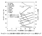
流れモジュレータの構成及び動作条件(表1)の変化が流体力学的キャビテーション反応装置内のキャビテーション状態に及ぼす効果は、水様流体に関して規定されるキャビテーション係数(図1)等の既定のパラメータに基づいてマッピングされる。(図1の)マップでの流れモジュレータにおける流速は、考慮される流れモジュレータの種々の構造特徴及び動作条件の範囲の効果を表している。本発明の一態様では、キャビテーション装置内で起こるキャビテーションの強度及びタイプと表1及び図1に示されるような範囲の幾何学的形状及び動作条件との間で関係が確立され、実証される。本発明の関連の態様では、図1と同様の様相マップを利用して、特定の目標プロセス強化に必要な所望のタイプのキャビテーションが同定され、続いて、所望且つ所定のプロセス強化を達成するように反応装置が設計される。 The effect of changes in flow modulator configuration and operating conditions (Table 1) on the cavitation conditions in the hydrodynamic cavitation reactor is based on predetermined parameters such as the cavitation coefficient (Figure 1) defined for water-like fluids. To be mapped. The flow velocity in the flow modulator on the map (of FIG. 1) represents the effect of the range of various structural features and operating conditions of the flow modulator considered. In one aspect of the invention, a relationship is established and demonstrated between the strength and type of cavitation occurring within the cavitation device and the range of geometric shapes and operating conditions as shown in Table 1 and FIG. In a related aspect of the invention, a modal map similar to that of FIG. 1 is utilized to identify the desired type of cavitation required for a particular target process enhancement, and subsequently to achieve the desired and predetermined process enhancement. A reactor is designed.
図1は、特定の(異なる幾何学的構成及び動作条件で得られる同一のキャビテーション係数)キャビテーション係数(キャビテーションの程度)に関して、多様な物理的及び化学的プロセスの強化のために水性及び非水性媒質中で調整されたキャビテーション状態を得るための流体力学的キャビテーション反応装置の設計に使用され得る流体力学的キャビテーション反応装置内のキャビテーション状態(過渡的又は安定又は活発)に、定量化可能な差があることを立証している。 FIG. 1 illustrates aqueous and non-aqueous media for enhancement of various physical and chemical processes with respect to a specific (identical cavitation coefficient obtained with different geometric configurations and operating conditions) and cavitation coefficient (degree of cavitation). There is a quantifiable difference in the cavitation state (transient or stable or active) within a hydrodynamic cavitation reactor that can be used to design a hydrodynamic cavitation reactor to obtain a calibrated cavitation state in I have proved that.
図1を利用して、流れモジュレータが存在する結果としての、流体力学的キャビテーション反応装置の構造特徴及び流速で表わされる動作条件の効果が分かり得る。以下の実施例で示されるように、本発明で提案されるこの方法を使用することで、幾何学的形状及び動作条件に応じて変換のタイプと反応装置内で生じているキャビテーション状態との間に明確な関係が確立されており、これにより、変換を支える上記物理学的作用/化学的作用を促進及び/又は強化することができる。したがって、図1を使用して、特定の所望のタイプの変換に望ましいキャビテーション状態/キャビテーションのタイプを得るように、所定の範囲の動作条件のためのキャビテーション反応装置を設計することができる。 FIG. 1 can be used to understand the effect of operating conditions expressed in terms of structural characteristics and flow rates of a hydrodynamic cavitation reactor as a result of the presence of a flow modulator. Using this method proposed in the present invention, as shown in the examples below, between the type of transformation and the cavitation conditions occurring in the reactor, depending on the geometry and operating conditions. A clear relationship has been established, which can promote and / or enhance the physical / chemical effects that support the transformation. Accordingly, FIG. 1 can be used to design a cavitation reactor for a given range of operating conditions to obtain the desired cavitation state / cavitation type for a particular desired type of conversion.
例えば、キャビティジェネレータ内の流速がキャビテーション反応装置内に生じているキャビテーション状態に及ぼす効果。図1から、1.0の閾値キャビテーション係数から初めてキャビテーションの発生(活発キャビテーション)が始まることが分かり得る。キャビテーション係数がさらに減少すると、キャビテーション係数0.22までキャビテーション事象が増加する。キャビテーション係数をさらにそれ以上減少させても、キャビテーション事象は増加しない。これは、流体主成分として主に水を含む水系で主に見られた。 For example, the effect of the flow rate in the cavity generator on the cavitation conditions occurring in the cavitation reactor. From FIG. 1, it can be seen that the generation of cavitation (active cavitation) starts only from the threshold cavitation coefficient of 1.0. As the cavitation factor further decreases, cavitation events increase to a cavitation factor of 0.22. Further reduction of the cavitation coefficient does not increase the cavitation event. This was mainly seen in water systems containing mainly water as the main fluid component.
図1から、キャビティジェネレータにおける液体速度を上昇させると、過渡的タイプのキャビテーションがますます優勢になることにより、生じているキャビテーション状態全体で安定タイプのキャビテーションの勢力を弱めることも分かり得る。しかしながら、0.22以下のキャビテーション係数では、過渡的キャビテーション及び安定キャビテーションの両方が、キャビテーション状態全体に等しく依存する(活発キャビティ%)。 It can also be seen from FIG. 1 that increasing the liquid velocity in the cavity generator makes the transient type cavitation increasingly prevalent, thereby reducing the power of the stable type cavitation throughout the resulting cavitation state. However, for cavitation coefficients below 0.22, both transient and stable cavitation are equally dependent on the overall cavitation state (active cavity%).
非水系に関するキャビテーションマップが図2に示されている。キャビテーション媒質に関する非水系は、本質的に、水と全く異なる密度、表面張力、及び粘度を特徴付けられる。本発明は、下記の範囲の物理化学的特性を有する任意の液体又は液体の混合物に関するキャビテーションシステムの設計について説明する。
密度:800kg/m3〜1500kg/m3(水:1000kg/m3)
粘度:1cP〜100cP(水:1cP)
表面張力:0.01N/m〜0.075N/m(水:0.072N/m)
蒸気圧:30℃で300N/m2〜101325N/m2(水:4200Pa)
A cavitation map for non-aqueous systems is shown in FIG. Non-aqueous systems for cavitation media are characterized by a density, surface tension, and viscosity that are essentially different from water. The present invention describes the design of a cavitation system for any liquid or mixture of liquids having the following range of physicochemical properties.
Density: 800kg / m 3 ~1500kg / m 3 ( water: 1000kg / m 3)
Viscosity: 1 cP to 100 cP (water: 1 cP)
Surface tension: 0.01 N / m to 0.075 N / m (water: 0.072 N / m)
Vapor pressure: at 30 ℃ 300N / m 2 ~101325N / m 2 ( water: 4200Pa)
反応/変換用の媒質は、反応物に対する溶解性/分散能を有すると共に反応物と同じ範囲の物理化学的特性を有する任意の適当な溶媒から選択され得る。 The reaction / conversion medium can be selected from any suitable solvent that has solubility / dispersibility in the reactants and has the same range of physicochemical properties as the reactants.
液体密度が高くなると(800kg/m3〜1500kg/m3の上記範囲で)、安定キャビテーションの程度が20%近く減少する(そして過渡的キャビテーションが増加する)ことが分かる。活発キャビティは、液体粘度が高くなると減少し、100cPを超えると存在しなくなる(図3)。0.01N/m〜0.075N/mの範囲の表面張力は、キャビテーション係数1及び0.37という2つの極端に異なる場合について、キャビテーションの程度又は性質を変えるのにそれほど大きな役割を果たさないことが分かった。無次元パラメータである「キャビテーション係数」は、液体の蒸気圧を考慮に入れたものであるため、蒸気圧の変動がキャビテーションマップに直接反映される。
The liquid density increases (in the above-mentioned range of 800kg / m 3 ~1500kg / m 3 ), the degree of stable cavitation is reduced nearly 20% (and transient cavitation is increased) can be seen. Active cavities decrease as the liquid viscosity increases and disappear after 100 cP (FIG. 3). Surface tension in the range of 0.01 N / m to 0.075 N / m does not play a big role in changing the degree or nature of cavitation for two extremely different cases,
したがって、液体力学的キャビテーション反応装置は、キャビテーション係数が、
「Ven_ori」及び「Orifice」では安定キャビテーションのための0.5〜1.0、
「Venturi」、「NC_ven」、「Ven_step4」、「Stepped2」、「Ori_Ven」、「Stepped4」では過渡的キャビテーションのための0.22〜0.5、
「Ven_ori」及び「Orifice」ではキャビテーションの同時安定及び過渡的のための0.22〜0.5
の範囲から選択され、物理的及び化学的プロセスの強化のために、水性及び非水性媒質中でキャビテーション状態を得るように設計することができる。
Therefore, the hydrodynamic cavitation reactor has a cavitation coefficient of
In “Ven_ori” and “Orifice”, 0.5 to 1.0 for stable cavitation,
In “Venturi”, “NC_ven”, “Ven_step4”, “Stepped2”, “Ori_Ven”, “Stepped4”, 0.22 to 0.5 for transient cavitation,
In “Ven_ori” and “Orifice” 0.22 to 0.5 for simultaneous stabilization and transient of cavitation
And can be designed to obtain cavitation in aqueous and non-aqueous media for enhanced physical and chemical processes.
したがって、本発明によると、物理的及び化学的プロセスの強化のために、水性及び非水性媒質中でキャビテーション状態を得るように流体力学的キャビテーション反応装置を調整する方法が、
それぞれ目標の物理的及び/又は化学的変換に必要な安定及び/又は過渡的キャビテーションを選択するステップであって、
過渡的キャビテーションは、均一系における化学的変換のために選択され、
安定キャビテーションは、不均一系における化学的変換及び均一系における物理的変換のために選択され、
安定キャビテーション及び過渡的キャビテーションの両方は、不均一系における物理的変換のために選択される、安定及び/又は過渡的キャビテーションを選択するステップと、
最初のステップにおいて選択された物理的又は化学的変換のための範囲からキャビテーション係数を選択するステップと、
選択されたキャビテーション係数での選択されたタイプのキャビテーションに関して活発キャビテーションを最大化するように、様相マップからキャビテーション室の幾何学的形状を選択するステップと、
処理すべき体積流量に関して上記選択された幾何学的形状及び上記キャビテーション係数の範囲内で、方程式3:
を含み、任意選択的に、キャビテーション室の選択されたタイプの幾何学的形状がオリフィスである場合、穴の流れ面積に対する穴の周囲長さの比であるαが最大化され且つ複数の穴の流れ面積の合計が上記面積と等しくなるように、最小サイズの複数の穴を選択して、穴の最小サイズが不均一相中の最大の硬質/半硬質粒子の少なくとも50倍であるようにすることによって、活発キャビテーションを最大化するための最適化が行われ、穴の最小サイズは1mmまでに制限され、
先行する化学的変換を含む乳化ステップを伴う液液不均一系における場合、ウェーバー数の追加基準=4.7が選択され、
ウェーバー数(We)は、破壊に抵抗する界面張力に対する破壊に関与する慣性力の比
上記キャビテーション室の幾何学的形状の選択されたタイプが多オリフィスキャビティジェネレータである場合、穴の間隔は、
![]()
Selecting stable and / or transient cavitation, respectively, required for the target physical and / or chemical transformations,
Transient cavitation is selected for chemical transformations in homogeneous systems,
Stable cavitation is selected for chemical transformations in heterogeneous systems and physical transformations in homogeneous systems,
Selecting stable and / or transient cavitation, both stable and transient cavitation are selected for physical transformation in a heterogeneous system;
Selecting a cavitation coefficient from the range for physical or chemical transformation selected in the first step;
Selecting a cavitation chamber geometry from the modal map to maximize active cavitation for a selected type of cavitation at a selected cavitation factor;
Within the selected geometry and the cavitation factor for the volume flow to be processed, Equation 3:
And optionally, if the selected type of geometry of the cavitation chamber is an orifice, the ratio of the perimeter of the hole to the hole flow area, α, is maximized and the plurality of holes Select the smallest size holes so that the sum of the flow areas is equal to the above area so that the smallest size of the holes is at least 50 times the largest hard / semi-hard particles in the heterogeneous phase. This optimizes to maximize active cavitation, and the minimum hole size is limited to 1 mm,
In a liquid-liquid heterogeneous system with an emulsification step involving a preceding chemical transformation, an additional criterion for Weber number = 4.7 is selected,
Weber number (We) is the ratio of inertial forces involved in fracture to interfacial tension resisting fracture
If the selected type of cavitation chamber geometry is a multi-orifice cavity generator, the hole spacing is
![]()
図1、図2、及び図4におけるような、キャビテーション室を通る流体又はスラリーの最大速度と、キャビテーション係数と、活発、過渡的、及び安定キャビテーションのパーセンテージとを相関させる様相マップが、
キャビティジェネレータ、流れモジュレータ、及び乱流モジュレータから成るキャビテーション室の幾何学的形状全体で、(P)液体における圧力、(u)表1に示す基準系に従ったx方向の速度成分、(v)表1に示す基準系に従ったy方向の速度成分、(w)表1に示す基準系に従ったz方向の速度成分、(k)乱流運動エネルギー、(ε)乱流エネルギー散逸速度、(ρ)液体密度、(σ)液体相の表面張力及び界面張力、(μ)液体粘度等の基本的な変数から成る適当な方程式を用いて、材料の連続性及び運動量収支、乱流運動量エネルギー、並びに乱流エネルギー散逸速度を確定するステップであって、
連続方程式は、
![]()
![]()
![]()
キャビテーション室を通るキャビティが辿る可能性のある経路の数「n」を得るステップであって、
nは、100よりも有意に大きく、
キャビティが辿る経路は、ラグランジュ方程式:
ラグランジュ方程式を数値的に解いてキャビティの時間依存座標が得られ、
ラグランジュ方程式(8)から得られる上記座標における収支の解(solution of balances)からPBulk、k、及びε□が得られる、経路の数「n」を得るステップと、
キャビティによって感知される圧力振幅(Pamp)、圧力周波数(f)、及び瞬間圧力(P∞)の値を、関係式
![]()
上記P∞、Pamp、fのデータを使用して、キャビティダイナミクスモデルからキャビティダイナミクス(時間の関数としてのキャビティ半径)を得るステップであって、
キャビティダイナミクスモデルは、Rayleigh−Plesset方程式族、例えば、
以下の基準を使用して、キャビティを活発、安定、及び過渡的キャビテーションとして分類するステップであって、
キャビティ内の圧力がキャビテーション室の入口における圧力の10倍を超える場合、キャビティが活発であり、
最終圧力がキャビティの寿命の間の該キャビティ内の最大圧力と等しくない場合、活発キャビティが安定キャビティであり、
最終圧力がキャビティ内の最大圧力と等しい場合、活発キャビティが過渡的キャビティである、分類するステップと、
所与の速度、キャビテーション係数、キャビテーション室の選択された幾何学的形状(形状及びサイズ)に関して、
活発キャビティの数÷キャビティの総数×100として活発キャビテーションのパーセンテージ、
安定キャビティの数÷活発キャビティの総数×100として安定キャビテーションのパーセンテージ、
過渡的キャビティの数÷活発キャビティの総数×100として過渡的キャビテーションのパーセンテージ、
を計算するステップと、
を含むプロセスによって得られる。
A modal map that correlates the maximum fluid or slurry velocity through the cavitation chamber, the cavitation coefficient, and the percentage of active, transient, and stable cavitation, as in FIGS.
(P) the pressure in the liquid, (u) the velocity component in the x direction according to the reference system shown in Table 1, over the entire geometry of the cavitation chamber consisting of the cavity generator, flow modulator, and turbulence modulator, (v) Velocity component in the y direction according to the reference system shown in Table 1, (w) velocity component in the z direction according to the reference system shown in Table 1, (k) turbulent kinetic energy, (ε) turbulent energy dissipation velocity, (Ρ) Liquid density, (σ) Surface tension and interfacial tension of the liquid phase, (μ) Liquid continuity and momentum balance, turbulent momentum energy, using appropriate equations consisting of basic variables such as liquid viscosity As well as determining the turbulent energy dissipation rate,
The continuity equation is
![]()
![]()
![]()
Obtaining the number “n” of paths that the cavity through the cavitation chamber may follow, comprising:
n is significantly greater than 100;
The path the cavity follows is the Lagrangian equation:
Numerically solving the Lagrangian equation gives the time-dependent coordinates of the cavity,
Obtaining the number “n” of paths from which P Bulk , k, and ε □ are obtained from the solution of balances in the coordinates obtained from the Lagrangian equation (8);
The values of pressure amplitude (P amp ), pressure frequency (f), and instantaneous pressure (P ∞ ) sensed by the cavity are expressed as a relational expression.
![]()
Obtaining the cavity dynamics (cavity radius as a function of time) from the cavity dynamics model using the above P ∞ , P amp , f data,
The cavity dynamics model is a Rayleigh-Plesset equation family, eg
Classifying the cavity as active, stable, and transient cavitation using the following criteria:
If the pressure in the cavity exceeds 10 times the pressure at the entrance of the cavitation chamber, the cavity is active,
If the final pressure is not equal to the maximum pressure in the cavity for the lifetime of the cavity, the active cavity is a stable cavity;
Classifying the active cavity as a transient cavity if the final pressure is equal to the maximum pressure in the cavity;
For a given speed, cavitation factor, and selected geometry (shape and size) of the cavitation chamber
Active cavitation percentage as number of active cavities ÷ total number of cavities x 100,
Number of stable cavities ÷ total number of active cavities × 100, percentage of stable cavitation,
The number of transient cavities ÷ total number of active cavities × 100 as a percentage of transient cavitation,
A step of calculating
Obtained by a process comprising:
上記方法を使用して、以下のようなキャビテーション室のさまざまな幾何学的形状を調整した。 Using the above method, various geometric shapes of the cavitation chamber were adjusted as follows.
i)「Venturi」は、
α値を最大化する円形又は非円形のキャビテーション室の最小断面積の一部又は全部であるキャビティジェネレータと、
キャビティジェネレータと称する最小断面積の上流で52度〜56度の全平均角度を有する平滑収束部、及びキャビティジェネレータの下流で20度〜25度の全平均角度を有する平滑発散部である、流れモジュレータと、
を備え、該「Venturi」は、流れの方向に連続して配置される3つの同軸部分から成る。
収束部は、
軸が直線であり、
断面積が全長にわたって円形であり、
導管の直径が流れ方向で0.93m/m〜1.06m/mの割合で減少し、
断面積がスロート部の断面積と等しくなると終端するようなものである。
スロート部は、
軸が直線であり、
導管の断面積が円形であり、
断面積が一定であり且つ方程式(3)から得られ、
長さがその直径の半分と等しいようなものである。
発散部は、
導管の軸が直線であり、
導管の断面積が全長にわたって円形であり、
導管の直径が流れ方向で0.35m/m〜0.44m/mの割合で減少し、
その長さが収束部の長さの2.64倍と等しいようなものである。
i) “Venturi”
a cavity generator that is part or all of the minimum cross-sectional area of a circular or non-circular cavitation chamber that maximizes the α value;
A flow modulator comprising a smooth convergence portion having a total average angle of 52 to 56 degrees upstream of a minimum cross-sectional area referred to as a cavity generator, and a smooth divergence portion having a total average angle of 20 to 25 degrees downstream of the cavity generator When,
The “Venturi” consists of three coaxial parts arranged in succession in the direction of flow.
The convergence part is
The axis is straight,
The cross-sectional area is circular over the entire length,
The diameter of the conduit decreases in the flow direction from 0.93 m / m to 1.06 m / m,
It terminates when the cross-sectional area becomes equal to the cross-sectional area of the throat portion.
The throat section
The axis is straight,
The cross-sectional area of the conduit is circular,
The cross-sectional area is constant and obtained from equation (3),
It is such that its length is equal to half its diameter.
Divergent part is
The axis of the conduit is straight,
The cross-sectional area of the conduit is circular over its entire length;
The diameter of the conduit decreases in the flow direction at a rate of 0.35 m / m to 0.44 m / m,
Its length is equal to 2.64 times the length of the converging part.
ii)「Ven_step4」は、
α値を最大化する円形又は非円形のキャビテーション室の最小断面積の一部又は全部であるキャビティジェネレータと、
上記キャビティジェネレータの下流にある乱流モジュレータであって、流れと平行な長軸に沿って配置され且つ繋ぎ合わせられて導管を形成する、キャビティジェネレータの最大寸法と等しい複数の長さ(幅)の部分を有する、乱流モジュレータと、
キャビティジェネレータの上流で52度〜56度の全平均角度を有する平滑収束部である流れモジュレータと、
を備え、該「Ven_step4」は、流れの方向に連続して配置される3つの同軸部分から成る。
収束部は、
軸が直線であり、
断面積が全長にわたって円形であり、
導管の直径が流れ方向で0.93m/m〜1.06m/mの割合で減少し、
断面積がスロート部の断面積と等しくなると終端するようなものである。
スロート部は、
軸が直線であり、
導管の断面積が円形であり、
断面積が一定であり且つ方程式(3)から得られ、
長さがその直径の半分であるようなものである。
発散部は、複数のオリフィスを含み、
後続のオリフィス板それぞれが前のオリフィス板に接触しており、
各オリフィス板が穴を1つだけ有し、
オリフィス板の穴すべてが円形であり且つスロート部の軸と同軸であり、
各オリフィス板の厚さがスロート部の長さの2倍であり、
後続のオリフィス板の直径が各オリフィス板の厚さの0.35倍〜0.44倍増加し、
長さが収束部の長さの2.64倍と等しいようなものである。
ii) "Ven_step4"
a cavity generator that is part or all of the minimum cross-sectional area of a circular or non-circular cavitation chamber that maximizes the α value;
A turbulence modulator downstream of the cavity generator, of a plurality of lengths (widths) equal to the maximum dimension of the cavity generator, arranged along a long axis parallel to the flow and joined together to form a conduit. A turbulence modulator having a portion;
A flow modulator that is a smooth converging section having a total average angle of 52 degrees to 56 degrees upstream of the cavity generator;
The “
The convergence part is
The axis is straight,
The cross-sectional area is circular over the entire length,
The diameter of the conduit decreases in the flow direction from 0.93 m / m to 1.06 m / m,
It terminates when the cross-sectional area becomes equal to the cross-sectional area of the throat portion.
The throat section
The axis is straight,
The cross-sectional area of the conduit is circular,
The cross-sectional area is constant and obtained from equation (3),
It's like the length is half of its diameter.
The divergence portion includes a plurality of orifices,
Each subsequent orifice plate is in contact with the previous orifice plate,
Each orifice plate has only one hole,
All holes in the orifice plate are circular and coaxial with the axis of the throat,
The thickness of each orifice plate is twice the length of the throat,
The diameter of subsequent orifice plates increases by 0.35 to 0.44 times the thickness of each orifice plate;
The length is such that it is equal to 2.64 times the length of the convergent portion.
iii)「Stepped2」は、
α値を最大化する円形又は非円形のキャビテーション室の最小断面積の一部又は全部であるキャビティジェネレータと、
上記キャビティジェネレータの下流及び上流にある乱流モジュレータであって、流れ面積が漸増する流れと平行な長軸に沿って配置され且つ繋ぎ合わせられて流れ面積が漸増する導管を形成し、上流で52度〜56度の全平均角度を再び有すると共に下流で20度〜25度の全平均角度を有する、キャビティジェネレータの最大寸法の半分と等しい複数の長さ(幅)の部分を有する、乱流モジュレータと、
を備え、該「Stepped2」は、流れの方向に連続して配置される3つの同軸部分から成る。
収束部は、複数のオリフィスを含み、
後続のオリフィス板それぞれが前のオリフィス板に接触しており、
各オリフィス板が穴を1つだけ有し、
オリフィス板の穴すべてが円形であり且つスロート部の軸と同軸であり、
各オリフィス板の厚さがスロート部の長さと等しく、
後続のオリフィス板の穴の直径が各オリフィス板の厚さの0.93倍〜1.06倍減少し、
穴の面積がスロート部の断面積と等しくなると終端するようなものである。
スロート部は、
軸が直線であり、
導管の断面積が円形であり、
断面積が一定であり且つ方程式(3)から得られ、
長さがその直径の半分であるようなものである。
発散部は、複数のオリフィスを含み、
後続のオリフィス板それぞれが前のオリフィス板に接触しており、
各オリフィス板が穴を1つだけ有し、
オリフィス板の穴すべてが円形であり且つスロート部の軸と同軸であり、
各オリフィス板の厚さがスロート部の長さに等しく、
後続のオリフィス板の直径が各オリフィス板の厚さの0.35倍〜0.44倍増加し、
長さが収束部の長さの2.64倍と等しいようなものである。
iii) “Stepped2”
a cavity generator that is part or all of the minimum cross-sectional area of a circular or non-circular cavitation chamber that maximizes the α value;
A turbulence modulator downstream and upstream of the cavity generator, wherein the turbulence modulators are arranged and joined together along a major axis parallel to the flow with increasing flow area to form a conduit with increasing flow area upstream of 52 Turbulence modulator having a plurality of lengths (widths) equal to half the maximum dimension of the cavity generator, again having a total average angle of -56 degrees and having a total average angle of 20-25 degrees downstream When,
The “Stepped2” consists of three coaxial parts arranged in succession in the direction of flow.
The converging portion includes a plurality of orifices,
Each subsequent orifice plate is in contact with the previous orifice plate,
Each orifice plate has only one hole,
All holes in the orifice plate are circular and coaxial with the axis of the throat,
The thickness of each orifice plate is equal to the length of the throat part,
The diameter of the holes in the subsequent orifice plate is reduced by 0.93 to 1.06 times the thickness of each orifice plate;
The hole ends when the area of the hole becomes equal to the cross-sectional area of the throat portion.
The throat section
The axis is straight,
The cross-sectional area of the conduit is circular,
The cross-sectional area is constant and obtained from equation (3),
It's like the length is half of its diameter.
The divergence portion includes a plurality of orifices,
Each subsequent orifice plate is in contact with the previous orifice plate,
Each orifice plate has only one hole,
All holes in the orifice plate are circular and coaxial with the axis of the throat,
The thickness of each orifice plate is equal to the length of the throat,
The diameter of subsequent orifice plates increases by 0.35 to 0.44 times the thickness of each orifice plate;
The length is such that it is equal to 2.64 times the length of the convergent portion.
iv)「Ori_Ven」は、
α値を最大化する円形又は非円形のキャビテーション室の最小断面積の一部又は全部であるキャビティジェネレータと、
キャビティジェネレータの下流で20度〜25度の全平均角度を有する平滑発散部である流れモジュレータと、
を備え、該「Ori_Ven」は、流れの方向に連続して配置される2つの同軸部分から成る。
スロート部は、
軸が直線であり、
導管の断面積が円形であり、
断面積が一定であり且つ方程式(3)から得られ、
長さがその直径の半分と等しいようなものである。
発散部は、
導管の軸が直線であり、
導管の断面積が全長にわたって円形であり、
導管の直径が流れ方向で0.35m/m〜0.44m/mの割合で増加し、
その長さが液体流速(m3/s)÷スロート部の面積(m2)×0.001mと等しいようなものである。
iv) “Ori_Ven”
a cavity generator that is part or all of the minimum cross-sectional area of a circular or non-circular cavitation chamber that maximizes the α value;
A flow modulator that is a smooth divergent section having a total average angle of 20-25 degrees downstream of the cavity generator;
The “Ori_Ven” consists of two coaxial parts arranged in succession in the direction of flow.
The throat section
The axis is straight,
The cross-sectional area of the conduit is circular,
The cross-sectional area is constant and obtained from equation (3),
It is such that its length is equal to half its diameter.
Divergent part is
The axis of the conduit is straight,
The cross-sectional area of the conduit is circular over its entire length;
The diameter of the conduit increases at a rate of 0.35 m / m to 0.44 m / m in the flow direction;
The length is equal to the liquid flow velocity (m 3 / s) ÷ the throat area (m 2 ) × 0.001 m.
v)「Stepped4」は、
α値を最大化する円形又は非円形のキャビテーション室の最小断面積の一部又は全部であるキャビティジェネレータと、
上記キャビティジェネレータの下流及び上流にある乱流モジュレータであって、流れ面積に関してそれぞれ漸減的及び漸増的に配置され、それぞれ20度〜25度及び52度〜56度の全平均角度を有する、上記キャビティジェネレータの最大寸法と等しい複数の長さ(幅)の部分の組み立て体としての、乱流モジュレータと、
を備え、該「Stepped4」は、流れの方向に連続して配置される3つの同軸部分から成る。
収束部は、複数のオリフィスを含み、
後続のオリフィス板それぞれが前のオリフィス板に接触しており、
各オリフィス板が穴を1つだけ有し、
オリフィス板の穴すべてが円形であり且つスロート部の軸と同軸であり、
各オリフィス板の厚さがスロート部の長さの2倍であり、
後続のオリフィス板の穴の直径が各オリフィス板の厚さの0.93倍〜1.06倍減少し、
オリフィス板の穴の面積がスロート部の断面積と等しくなると終端するようなものである。
スロート部は、
軸が直線であり、
導管の断面積が円形であり、
断面積が一定であり且つ方程式(3)から得られ、
長さがその直径の半分であるようなものである。
発散部は、複数のオリフィスを含み、
後続のオリフィス板それぞれが前のオリフィス板に接触しており、
各オリフィス板が穴を1つだけ有し、
オリフィス板の穴すべてが円形であり且つスロート部の軸と同軸であり、
各オリフィス板の厚さがスロート部の長さの2倍であり、
後続のオリフィス板の直径が各オリフィス板の厚さの0.35倍〜0.44倍増加し、
長さが収束部の長さの2.64倍と等しいようなものである。
v) “Stepped4”
a cavity generator that is part or all of the minimum cross-sectional area of a circular or non-circular cavitation chamber that maximizes the α value;
A turbulence modulator downstream and upstream of the cavity generator, wherein the cavity is arranged in a decreasing and increasing manner with respect to the flow area, respectively, and has a total average angle of 20 to 25 degrees and 52 to 56 degrees, respectively. A turbulence modulator as an assembly of multiple lengths (widths) equal to the maximum dimension of the generator;
The “Stepped 4” consists of three coaxial parts arranged in succession in the direction of flow.
The converging portion includes a plurality of orifices,
Each subsequent orifice plate is in contact with the previous orifice plate,
Each orifice plate has only one hole,
All holes in the orifice plate are circular and coaxial with the axis of the throat,
The thickness of each orifice plate is twice the length of the throat,
The diameter of the holes in the subsequent orifice plate is reduced by 0.93 to 1.06 times the thickness of each orifice plate;
It terminates when the area of the hole in the orifice plate is equal to the cross-sectional area of the throat.
The throat section
The axis is straight,
The cross-sectional area of the conduit is circular,
The cross-sectional area is constant and obtained from equation (3),
It's like the length is half of its diameter.
The divergence portion includes a plurality of orifices,
Each subsequent orifice plate is in contact with the previous orifice plate,
Each orifice plate has only one hole,
All holes in the orifice plate are circular and coaxial with the axis of the throat,
The thickness of each orifice plate is twice the length of the throat,
The diameter of subsequent orifice plates increases by 0.35 to 0.44 times the thickness of each orifice plate;
The length is such that it is equal to 2.64 times the length of the convergent portion.
vi)「Ven_Ori」は、
α値を最大化する任意の形状のキャビテーション室の最小断面積の一部であるキャビティジェネレータと、
キャビティジェネレータの上流に対して52度〜56度の角度を有する平滑収束部である流れモジュレータと、
を備え、該「Ven_Ori」は、流れの方向に連続して配置される2つの同軸部分から成る。
収束部は、
軸が直線であり、
断面積が全長にわたって円形であり、
導管の直径が流れ方向で0.93m/m〜1.06m/mの割合で減少し、
断面積がスロート部の断面積と等しくなると終端するようなものである。
スロート部は、
軸が直線であり、
導管の断面積が円形であり、
断面積が一定であり且つ方程式(3)から得られ、
長さがその直径の半分と等しいようなものである。
vi) “Ven_Ori”
a cavity generator that is part of the minimum cross-sectional area of an arbitrarily shaped cavitation chamber that maximizes the α value;
A flow modulator that is a smooth converging section having an angle of 52 degrees to 56 degrees upstream of the cavity generator;
The “Ven_Ori” consists of two coaxial parts arranged in succession in the direction of flow.
The convergence part is
The axis is straight,
The cross-sectional area is circular over the entire length,
The diameter of the conduit decreases in the flow direction from 0.93 m / m to 1.06 m / m,
It terminates when the cross-sectional area becomes equal to the cross-sectional area of the throat portion.
The throat section
The axis is straight,
The cross-sectional area of the conduit is circular,
The cross-sectional area is constant and obtained from equation (3),
It is such that its length is equal to half its diameter.
vii)「Orifice」は、
α値を最大化する円形又は非円形のキャビテーション室の最小断面積の一部又は全部であるキャビティジェネレータ、
を備える。
該Orificeは、
軸が直線であり、
導管の断面積が円形であり、
断面積が一定であり且つ方程式(3)から得られ、
長さがその直径の半分と等しいようなスロート部から成る。
vii) “Orifice”
a cavity generator that is part or all of the minimum cross-sectional area of a circular or non-circular cavitation chamber that maximizes the α value;
Is provided.
The Office is
The axis is straight,
The cross-sectional area of the conduit is circular,
The cross-sectional area is constant and obtained from equation (3),
It consists of a throat part whose length is equal to half its diameter.
viii)「NC_ven」は、
α値を最大化する非円形のキャビテーション室の最小断面積の一部又は全部であるキャビティジェネレータと、
キャビティジェネレータの上流で52度〜56度の全平均角度を有する平滑収束部、及びキャビティジェネレータの下流で20度〜25度の全平均角度を有する平滑発散部であり、上記キャビティジェネレータの下流で同じか又は異なるが非円形の形状を維持する、流れモジュレータと、
を備える。
viii) "NC_ven"
a cavity generator that is part or all of the minimum cross-sectional area of a non-circular cavitation chamber that maximizes the α value;
A smooth convergence portion having an overall average angle of 52 to 56 degrees upstream of the cavity generator and a smooth diverging portion having an overall average angle of 20 to 25 degrees downstream of the cavity generator, the same downstream of the cavity generator A flow modulator that maintains a different but non-circular shape;
Is provided.
次に、細菌の破壊による水の消毒、ローダミンの分解、トルエンの酸化、冷却塔内の生物付着、脂肪酸のエステル化、及び可溶性炭素の放出のような、特定の物理的、化学的、又は生物学的変換におけるプロセス強化に関与する流体力学的キャビテーションの使用のための反応装置の設計の非限定的な実施例を用いて、本発明を説明する。幾何学的形状、エネルギー消費、キャビテーション最適化の効果に関連する実施例も含まれている。 Next, specific physical, chemical, or biological, such as water disinfection by bacterial destruction, rhodamine degradation, toluene oxidation, biofouling in cooling towers, fatty acid esterification, and soluble carbon release The present invention will be described using a non-limiting example of a reactor design for the use of hydrodynamic cavitation involved in process enhancement in a chemical transformation. Examples relating to the effects of geometry, energy consumption, and cavitation optimization are also included.
設計特徴、動作条件、キャビテーション状態、及びこれらのキャビテーション状態が種々の変換に及ぼす効果を、表2aに示す。流体力学的キャビテーション反応装置の設計について、これらのキャビテーション装置(表2aに示すように最初にシミュレートされた異なる構成のオリフィス板)を製造して実験により試験し、図1を実証した。 Table 2a shows the design features, operating conditions, cavitation states, and the effects of these cavitation states on various transformations. For the design of the hydrodynamic cavitation reactor, these cavitation devices (differently configured orifice plates initially simulated as shown in Table 2a) were manufactured and experimentally tested to demonstrate FIG.
図1を実証し、続いて特定のプロセス強化を実行するように反応装置を設計すると共に上述のような図1の用途を説明するのに使用した。 FIG. 1 was verified and subsequently used to describe the application of FIG. 1 as described above and to design the reactor to perform specific process enhancements.
キャビテーション室の幾何学的解析
代表的な液体流速2.5×10⁻⁴m3/s及びキャビテーション係数0.5に対応するように、キャビテーション室の種々の幾何学低形状を設計した。上記パラメータは、説明のために選択されているに過ぎないが、提示された手法及びそこで得られる設計を、これらの動作パラメータ及び設計パラメータの範囲で利用することができる。キャビティジェネレータの面積を、上述の代表的な液体流速(2.5×10−4m3/s)及び選択したキャビテーション係数(0.5)について方程式(3)から計算し、1.26×10−5m2を得た。本手法に基づき、キャビテーション装置のいくつかの形状を得ると共にキャビテーション挙動について解析した。
Cavitation chamber geometric analysis Various geometric low shapes of the cavitation chamber were designed to correspond to a typical liquid flow rate of 2.5 × 10 −4 m 3 / s and a cavitation factor of 0.5. The above parameters have been selected for illustration only, but the presented approach and the resulting design can be utilized within a range of these operating and design parameters. The area of the cavity generator is calculated from equation (3) for the typical liquid flow rate described above (2.5 × 10 −4 m 3 / s) and the selected cavitation coefficient (0.5), and 1.26 × 10 6 -5 m 2 was obtained. Based on this method, several shapes of cavitation devices were obtained and the cavitation behavior was analyzed.
種々の設計で予測される圧力低下を表3に示す。所与の液体流速では、最小圧力低下(0.475atm)がベンチュリで起こる一方で最大圧力低下(3.15atm)がオリフィスで起こることが分かる。「ori_ven」の場合の圧力低下(1.55atm)は、「ven_ori」の圧力低下(2.13atm)よりも小さい。 Table 3 shows the pressure drop expected for various designs. It can be seen that for a given liquid flow rate, a minimum pressure drop (0.475 atm) occurs at the venturi while a maximum pressure drop (3.15 atm) occurs at the orifice. The pressure drop (1.55 atm) in the case of “ori_ven” is smaller than the pressure drop (2.13 atm) of “ven_ori”.
表3は、種々の設計で注入される全キャビティのうちの活発キャビティのパーセントを示す。オリフィスのような急激な拡大ではなく、下流部が発散状である(ベンチュリ/段状)である場合に、活発キャビティのパーセントが高くなることが分かる。 Table 3 shows the percentage of active cavities out of the total cavities injected with various designs. It can be seen that the percentage of active cavities is higher when the downstream is divergent (venturi / stepped) rather than a sudden expansion like the orifice.
表3は、いくつかの設計で形成される活発及び過渡的キャビティの程度を詳述している。表3は、本発明から得られる単位圧力低下あたりの活発キャビティのパーセンテージ及び単位圧力低下あたりの過渡的キャビティのパーセントを示す。本手法を使用することで、キャビテーション装置のキャビテーション挙動を定量化することが可能となり、所与の物理化学的変換に関して最適化された幾何学的形状及び動作パラメータを達成することができる。 Table 3 details the extent of active and transient cavities formed in some designs. Table 3 shows the percentage of active cavities per unit pressure drop and the percentage of transient cavities per unit pressure drop obtained from the present invention. Using this approach, it is possible to quantify the cavitation behavior of the cavitation device and achieve optimized geometry and operating parameters for a given physicochemical transformation.
種々の設計に関するキャビテーション様相マップを本手法に基づいて生成し、図1に示す。実線は活発キャビティの程度を示し、点線は安定キャビティの程度を示す。キャビテーション様相マップを使用して、キャビテーション要素の任意の設計に関して動作パラメータ(キャビテーション係数)を決定することができる。図1は、水様物質のキャビテーション様相マップを示しているが、上記で行った説明に基づいて、密度、粘度、表面張力、及び蒸気圧が実質的に異なる液体に関してキャビテーション様相マップを変更することができる(図2)。 Cavitation modal maps for various designs are generated based on this method and are shown in FIG. The solid line indicates the extent of active cavities and the dotted line indicates the extent of stable cavities. Cavitation modal maps can be used to determine operating parameters (cavitation factors) for any design of cavitation elements. FIG. 1 shows a cavitation modal map of a watery substance, but based on the explanation given above, changing the cavitation modal map for liquids with substantially different densities, viscosities, surface tensions, and vapor pressures. (Fig. 2).
流体力学的キャビテーションを使用した飲用水の消毒/細菌の破壊
水の消毒、排水の処理、生物付着の回避、酵素の回収等のいくつかの用途のために、微生物細胞の破壊を実行する。微生物細胞付近でキャビティが崩壊するか(過渡的キャビテーション)又は急速に体積振動する(安定キャビテーション)と、微生物細胞は破壊される。過渡的又は安定キャビテーションによって生じて加えられた応力が細胞強度よりも有意に大きければ、細胞壁が破壊される。したがって、両方のタイプのキャビテーションが、細胞破壊の程度を高める(assist)可能性が高い。微生物消毒は、不均一系におけるキャビテーションの物理的効果により起こる。したがって、安定及び過渡的キャビテーションの両方を微生物細胞の破壊のために最大化すべきである。図1に示す様相マップから、オリフィスに関して最大の安定キャビテーションを与える0.22〜0.5の範囲でキャビテーション係数を選択する。上記範囲から選択したキャビテーション係数0.28について、6.73×10−4m3/sの流量に関するオリフィスの穴の面積を方程式(3)から計算し、2.55×10−5m2を得た。この穴の面積は、直径5.70mmの単一の穴に相当する。選択したキャビテーション室はオリフィス板であったため、α値(開口面積に対する穴の周囲長さの比)を最大化する必要がある。最大のα値を与える制限値1mmを選択する。それに従って、直径1mmの穴を33個有するオリフィス板を設計し製造した。異なる入口圧力でのキャビテーション要素(オリフィス板)の性能特性を表2bに示す。表2aから、入口圧力の上昇に伴ってキャビテーションの強度(活発キャビティのパーセント)が高くなり、それに起因して消毒のパーセンテージも高くなることが分かり得る。入口圧力が4倍上昇すると(1.72バールから5.77バール)、活発キャビテーションが13倍増加し、それにより消毒は50%増加した。前述のように、キャビテーションのタイプ(過渡的又は安定)は、水の消毒に大きな影響を及ぼす。約14m/s(w−1)という低い液体速度で実行した水の消毒に関する研究では、過渡的キャビティがごく僅かしか存在しない結果として、振動(安定)キャビティから得られる実質的消毒が約60%であることが示された。さらに、過渡的キャビテーション量が53%増加すると、消毒に50%の増加が見られ、これは過渡的キャビテーション効果と消毒との間にほぼ一対一の対応があることを示す。したがって、図1及び図4に基づいて安定キャビテーション又は過渡的キャビテーションでキャビテーション装置を設計し動作させることによって、物理的変換に関して必要な効果が得られる。したがって、不均一系における微生物細胞の破壊用の調整キャビテーション反応装置は、安定及び過渡的キャビテーションで動作するように設計されており、該装置では、6.73×10−4m3/sの流量に関してキャビテーション係数が0.22〜0.5から、好ましくは0.28に選択され、オリフィスの穴の面積が、直径5.70mmの単一の穴に相当する2.55×10−5m2であり、最小穴径が、α値を最大化するように、但し穴径が1mmであるときの制限値まで最大化するように選択されることにより、33個の穴になると必要な総流れ面積が得られ、39%の活発キャビテーションが起こり、そのうち安定キャビテーションの程度は46%であり、結果として86%の細胞破壊が得られる。
Disinfection of potable water using hydrodynamic cavitation / bacterial destruction Perform microbial cell destruction for several applications such as water disinfection, wastewater treatment, avoidance of biofouling, enzyme recovery. If the cavity collapses near the microbial cell (transient cavitation) or rapidly oscillates (stable cavitation), the microbial cell is destroyed. If the applied stress caused by transient or stable cavitation is significantly greater than the cell strength, the cell wall is destroyed. Thus, both types of cavitation are likely to increase the degree of cell destruction. Microbial disinfection occurs due to the physical effects of cavitation in heterogeneous systems. Therefore, both stable and transient cavitation should be maximized for microbial cell destruction. From the appearance map shown in FIG. 1, a cavitation coefficient is selected in the range of 0.22 to 0.5 that gives the maximum stable cavitation for the orifice. For the cavitation factor of 0.28 selected from the above range, the orifice hole area for a flow rate of 6.73 × 10 −4 m 3 / s is calculated from equation (3) and 2.55 × 10 −5 m 2 is Obtained. The area of this hole corresponds to a single hole having a diameter of 5.70 mm. Since the selected cavitation chamber was an orifice plate, the α value (ratio of the perimeter of the hole to the opening area) needs to be maximized. A limit value of 1 mm that gives the maximum α value is selected. Accordingly, an orifice plate having 33 holes with a diameter of 1 mm was designed and manufactured. The performance characteristics of the cavitation element (orifice plate) at different inlet pressures are shown in Table 2b. From Table 2a it can be seen that as the inlet pressure increases, the strength of the cavitation (percent of active cavities) increases and thus the percentage of disinfection also increases. When the inlet pressure increased by a factor of 4 (1.72 bar to 5.77 bar), the active cavitation increased by a factor of 13, which resulted in a 50% increase in disinfection. As mentioned above, the type of cavitation (transient or stable) has a significant effect on water disinfection. Studies on water disinfection carried out at low liquid velocities of about 14 m / s (w-1) show that about 60% of the substantial disinfection obtained from a vibrating (stable) cavity results from the presence of very few transient cavities. It was shown that. Furthermore, when the amount of transient cavitation increases by 53%, there is a 50% increase in disinfection, indicating that there is a nearly one-to-one correspondence between transient cavitation effects and disinfection. Therefore, by designing and operating the cavitation device with stable cavitation or transient cavitation based on FIGS. 1 and 4, the necessary effect on the physical conversion can be obtained. Thus, a regulated cavitation reactor for the destruction of microbial cells in heterogeneous systems is designed to operate with stable and transient cavitation, with a flow rate of 6.73 × 10 −4 m 3 / s. The cavitation coefficient is selected from 0.22 to 0.5, preferably 0.28, and the orifice hole area is 2.55 × 10 −5 m 2 corresponding to a single hole with a diameter of 5.70 mm. The minimum flow diameter is chosen to maximize the α value, but to the maximum value when the hole diameter is 1 mm, so that the total flow required for 33 holes is achieved. Area is obtained and 39% active cavitation occurs, of which the degree of stable cavitation is 46%, resulting in 86% cell destruction.
流体力学的キャビテーションを使用したローダミンの分解
ローダミンは、繊維工業で一般に使用される芳香族アミン染料である。そのような汚染物質を含有する廃液流を脱色することが必要となる。キャビテーションは、そのような分子の発色団を破壊することで廃液流を脱色する。これは、均一系における物理的変換である。したがって、安定キャビテーションをこのような変換のために最大化すべきである。図1に示す様相マップから、キャビテーション係数は、オリフィスに関して最大の安定キャビテーションを与える0.5〜1.0の範囲にあるべきである。選択したキャビテーション係数範囲から、キャビテーション係数0.78を選択し、4.08×10−4m3/sの流量に関するオリフィスの開口面積を方程式(3)から計算し、2.59×10−5m2を得た。この開口面積は、直径5.7mmの単一の穴に相当する。選択したキャビテーション室はオリフィス板であったため、α値(開口面積に対する穴の周囲の比)を最大化する必要がある。最大のα値を与える制限値1mmを選択する。この幾何学的形状と共に、α値を変えた(2及び1.33)いくつかの他の設計のオリフィス板も設計し製造して、流体力学的キャビテーションを発生させる能力を比較した(詳細は表2aを参照)。同じ入口圧力での3つの異なるオリフィス板の性能特性を表2aに示す。表2bから、入口圧力が同じ場合、ローダミンの分解パーセンテージがキャビテーション要素の幾何学的形状によって変わることが分かり得る。分解パーセンテージは、α値(表2a)の増加と共に増加した。R−1及びR−2の比較(図4)は、活発キャビティが同量である場合、5%の過渡的キャビテーションの発生が分解を約50%高め得ることを示す。同様に、R−3及びR−2の構成の比較から、R−3の構成では活発キャビテーションの量が32%減少しているが(図4)、分解の減少は僅かである(1%)ことが判明する。これは、R−3の場合に過渡的キャビテーションの量が約25%増加することに起因し得る。これは、図4によって発生及び予測されると共にキャビテーション要素の構造特徴によって得られるタイプのキャビテーションが、分子結合の破壊に基づくローダミンの分解において重要な役割を果たすことで、発色団が破壊されて脱色が得られることを明らかに示す。上述の理由から、α値を最大にして所与の手法に基づいて設計されたオリフィス板が他の設計と比較して最大の変換度を与えることが分かる。したがって、ローダミンの分解用の調整キャビテーション反応装置は、安定キャビテーションで動作するように設計されており、該装置では、4.08×10−4m3/sの流量に関して最大の安定キャビテーションを達成するために、キャビテーション係数が0.5〜1.0から、好ましくは0.78に選択され、オリフィスの穴の面積が直径5.7mmの単一の穴に相当する2.59×10−5m2であり、最小穴径が、α値を最大化するように、但し穴径が1mmであるときの制限値まで最大化するように選択されることにより、33個の穴になると総流れ面積及び95%の安定キャビテーションが得られ、結果として17%のローダミンの分解が得られる。
Degradation of rhodamine using hydrodynamic cavitation Rhodamine is an aromatic amine dye commonly used in the textile industry. It is necessary to decolorize the waste stream containing such contaminants. Cavitation decolorizes the waste stream by destroying the chromophores of such molecules. This is a physical transformation in a homogeneous system. Therefore, stable cavitation should be maximized for such conversions. From the modal map shown in FIG. 1, the cavitation coefficient should be in the range of 0.5 to 1.0 giving the maximum stable cavitation for the orifice. From the selected cavitation coefficient range, a cavitation coefficient of 0.78 is selected, the orifice opening area for a flow rate of 4.08 × 10 −4 m 3 / s is calculated from equation (3), and 2.59 × 10 −5 m 2 was obtained. This open area corresponds to a single hole with a diameter of 5.7 mm. Since the selected cavitation chamber was an orifice plate, the α value (ratio of the hole circumference to the opening area) needs to be maximized. A limit value of 1 mm that gives the maximum α value is selected. Along with this geometry, several other designs of orifice plates with varying alpha values (2 and 1.33) were also designed and manufactured to compare their ability to generate hydrodynamic cavitation (details are given in Tables). See 2a). The performance characteristics of three different orifice plates at the same inlet pressure are shown in Table 2a. From Table 2b it can be seen that for the same inlet pressure, the degradation percentage of rhodamine varies with the geometry of the cavitation element. The percentage degradation increased with increasing α value (Table 2a). A comparison of R-1 and R-2 (FIG. 4) shows that the occurrence of 5% transient cavitation can increase degradation by about 50% when the active cavities are the same amount. Similarly, comparing the configurations of R-3 and R-2, the amount of active cavitation is reduced by 32% in the configuration of R-3 (FIG. 4), but the reduction in decomposition is slight (1%). It turns out. This can be attributed to an approximately 25% increase in the amount of transient cavitation for R-3. This is because the type of cavitation generated and predicted by FIG. 4 and obtained by the structural features of the cavitation element plays an important role in the degradation of rhodamine based on the breakage of molecular bonds, thereby destroying the chromophore and decolorizing it. Clearly show that For the reasons described above, it can be seen that an orifice plate designed based on a given approach with a maximum α value gives the maximum degree of conversion compared to other designs. Thus, the regulated cavitation reactor for the degradation of rhodamine is designed to operate with stable cavitation, which achieves maximum stable cavitation for a flow rate of 4.08 × 10 −4 m 3 / s. Therefore, the cavitation coefficient is selected from 0.5 to 1.0, preferably 0.78, and the hole area of the orifice is 2.59 × 10 −5 m corresponding to a single hole having a diameter of 5.7 mm. 2 and the minimum hole diameter is selected to maximize the α value, but to the limit value when the hole diameter is 1 mm, so that the total flow area is 33 holes. And 95% stable cavitation, resulting in 17% degradation of rhodamine.
流体力学的キャビテーションを使用したトルエンの酸化
対応するアリールカルボン酸へのアルキルアレーンの酸化は、工業的に重要なプロセスである。工業的に、そのような酸化は、高温及び高圧条件下で希硝酸又は空気を使用して実行される。これは、不均一系であり、反応物の十分な混合を達成するために高い撹拌速度を必要とする。流体力学的キャビテーションは、反応物の微細エマルションを生成し、アルキルアレーンの酸化のためのラジカルも生成する。流体力学的キャビテーションを使用して、トルエンの酸化を実行した。これは、不均一系における化学的変換である。したがって、安定キャビテーションをこのような変換のために最大化すべきである。図1に示す様相マップから、キャビテーション係数は、オリフィスに関して最大の安定キャビテーションを与える0.5〜1.0の範囲とすべきである。選択したキャビテーション係数範囲から、キャビテーション係数0.78を選択し、22.2×10⁻⁴m3/sの流量に関するオリフィスの開口面積を方程式(3)から計算し、11.3×10−5m2を得た。この開口面積は、直径12mmの単一の穴に相当する。選択したキャビテーション室はオリフィス板であったため、α値(開口面積に対する穴の周囲の比)を最大化する必要がある。α値を最大化するために、最小の穴を、不均一相中の最大の硬質/半硬質粒子のサイズの少なくとも50倍に、但し1mmの値までに制限して選択する。液液不均一系に関して説明した方法に従って、ウェーバー数の基準(Weber number criterion)(We=4.7)によって分散相の最大サイズを得る。2.5m/sの乱流変動速度に関して、ウェーバー数から得られる分散相のサイズは0.051mmである。したがって、穴の制限値は、(50×0.0051)2.51mmとなり、製造を容易にするために四捨五入して3mmとすべきである。したがって、直径3mmの16個の穴を有するオリフィスを設計し製造した。この設計と共に、α値が2であるもう1つの設計を製造して、性能を比較した。表2aは、使用した幾何学的形状及び動作条件の詳細を示す。T−2及びT−4の場合の比較から、活発(図4)キャビテーションの量が20%増加すると変換が26%増加することが判明する。この反応は、全体的な反応の進行及び強化のために物理的(振動キャビティにより制御される乳化)及び化学的(過渡的キャビティにより制御される酸化)効果を必要とするため、安定キャビティの役割が相関付けられる。液液不均一系におけるトルエンの酸化用の調整キャビテーション反応装置は、最大化された安定キャビテーションで動作するように設計されており、該装置では、22.2×10−4m3/sの流量に関して活発キャビテーションのパーセンテージを最大化するために、キャビテーション係数が0.5〜1.0から、好ましくはキャビテーション係数0.78に、より好ましくはキャビテーション係数0.5に選択され、オリフィスの穴の面積は、直径12mmの単一の穴に相当する11.3×10−5m2であり、任意選択的に、最小穴径が、α値を最大化するように、但し穴径が1mm又は最大の硬質/半硬質粒子のサイズの少なくとも50倍であるときの制限値まで最大化するように選択されることで、最小直径が約2.51mmの穴が得られることにより、直径3mmの16個の穴を有するオリフィス板になり、90.3%の安定キャビテーションが得られる結果として53%のトルエンの酸化が得られるか、又はキャビテーション係数0.4で80%の安定キャビテーションが得られる結果として54%のトルエンの酸化が得られる。
Oxidation of toluene using hydrodynamic cavitation Oxidation of alkyl arenes to the corresponding aryl carboxylic acids is an industrially important process. Industrially, such oxidation is carried out using dilute nitric acid or air under high temperature and pressure conditions. This is a heterogeneous system and requires high agitation rates to achieve sufficient mixing of the reactants. Hydrodynamic cavitation produces a fine emulsion of the reactants and also generates radicals for the oxidation of the alkyl arenes. Toluene oxidation was performed using hydrodynamic cavitation. This is a chemical transformation in a heterogeneous system. Therefore, stable cavitation should be maximized for such conversions. From the modal map shown in FIG. 1, the cavitation coefficient should be in the range of 0.5 to 1.0 giving the maximum stable cavitation for the orifice. From the selected cavitation coefficient range, a cavitation coefficient of 0.78 is selected, the orifice opening area for a flow rate of 22.2 × 10 −4 m 3 / s is calculated from equation (3), and 11.3 × 10 −5 m 2 was obtained. This open area corresponds to a single hole with a diameter of 12 mm. Since the selected cavitation chamber was an orifice plate, the α value (ratio of the hole circumference to the opening area) needs to be maximized. In order to maximize the α value, the smallest hole is selected at least 50 times the size of the largest hard / semi-hard particle in the heterogeneous phase, but limited to a value of 1 mm. According to the method described for the liquid-liquid heterogeneous system, the maximum size of the dispersed phase is obtained by the Weber number criterion (We = 4.7). For a turbulent fluctuation rate of 2.5 m / s, the size of the dispersed phase obtained from the Weber number is 0.051 mm. Therefore, the limit value of the hole is (50 × 0.0051) 2.51 mm, and should be rounded to 3 mm for ease of manufacture. Therefore, an orifice having 16
キャビテーションを使用した冷却塔内の生物付着の除去
冷却塔の水中における微生物成長(藻類/菌類)は、冷却塔及び関連の熱交換装置内の生物付着につながる。安定及び過渡的キャビテーションを微生物細胞破壊のために最大化すべきであり、したがって、キャビテーション室がこのような用途のために最大の活発キャビテーションを与えるべきである。そのため、上記方法に従って、圧力低下が最小のベンチュリで最大の活発キャビテーションを与えるように、キャビテーション係数を0.5〜1.0の範囲内で選択する。上記範囲から選択したキャビテーション係数0.8について、3.14×10−2m3/sの流量に関するベンチュリのスロートの面積を方程式(3)から計算し、12.57×10−4m2を得た。2.5atmの吐出圧力及び25m/sと等しい速度を維持することによって、キャビテーション係数を0.8に保った。上記動作パラメータでのキャビテーション室の選択された設計により、26%の活発キャビテーション及び10%の過渡的キャビテーションが発生する。表4は、冷却ループを循環している水から13日間で100000CFU/mlから0CFU/mlに細菌数が減ることを示す。
Removal of biofouling in cooling towers using cavitation Microbial growth (algae / fungi) in cooling tower water leads to biofouling in cooling towers and associated heat exchange devices. Stable and transient cavitation should be maximized for microbial cell destruction, and thus the cavitation chamber should provide maximum active cavitation for such applications. Therefore, according to the above method, the cavitation coefficient is selected within the range of 0.5 to 1.0 so as to give the maximum active cavitation with the minimum pressure drop venturi. For a cavitation factor of 0.8 selected from the above range, the area of the venturi throat for a flow rate of 3.14 × 10 −2 m 3 / s is calculated from equation (3) and 12.57 × 10 −4 m 2 is Obtained. The cavitation coefficient was kept at 0.8 by maintaining a discharge pressure of 2.5 atm and a speed equal to 25 m / s. The selected design of the cavitation chamber with the above operating parameters results in 26% active cavitation and 10% transient cavitation. Table 4 shows that the number of bacteria decreases from 100,000 CFU / ml to 0 CFU / ml in 13 days from the water circulating in the cooling loop.
したがって、不均一系における生物付着の除去用の調整キャビテーション反応装置は、安定及び過渡的キャビテーションで動作するように設計されており、該装置では、3.14×10⁻²m3/sの流量に関して、キャビテーション係数が0.5〜1から、好ましくは0.8に選択され、ベンチュリのキャビティジェネレータの面積が、直径40mmのキャビティジェネレータに相当する12.57×10−4m2であり、26%の活発キャビテーションが起こり、そのうち過渡的キャビテーションの程度は10%であり、結果として細菌数が100%減少する。 Thus, a regulated cavitation reactor for removal of biofouling in heterogeneous systems is designed to operate with stable and transient cavitation, where the flow rate is 3.14 × 10 −2 m 3 / s. , The cavitation coefficient is selected from 0.5 to 1, preferably 0.8, and the area of the venturi cavity generator is 12.57 × 10 −4 m 2 , corresponding to a cavity generator with a diameter of 40 mm, % Active cavitation occurs, of which the degree of transient cavitation is 10%, resulting in a 100% reduction in bacterial count.
流体力学的キャビテーションを使用したC8/C10脂肪酸のエステル化
流体力学的キャビテーションを使用して、メタノールで脂肪酸のエステル化を実行し、メチルエステルを生成した。不均一系におけるそのような化学的変換のための安定キャビテーションを、そのような変換のために最大化する必要がある。そのため、本方法に従って、キャビテーション係数は、オリフィスに関して最大の安定キャビテーションを与える0.5〜1.0の範囲とすべきである。選択したキャビテーション係数範囲から、キャビテーション係数0.78を選択し、22.2×10⁻⁴m3/sの流量に関するオリフィスの開口面積を方程式(3)から計算し、11.3×10−5m2を得た。この開口面積は、直径12mmの単一の穴に相当する。選択したキャビテーション室はオリフィス板であったため、α値(開口面積に対する穴の周囲の比)を最大化する必要があり、そのために、最小の穴を、不均一相中の最大の硬質/半硬質粒子のサイズの少なくとも50倍に、但し1mmの値までに制限して選択する。液液不均一系に関して説明した方法に従って、ウェーバー数の基準(We=4.7)によって分散相の最大サイズを得る。2.5m/sの乱流変動速度に関して、ウェーバー数から得られる分散相のサイズは0.051mmである。したがって、穴の制限値は、(50×0.0051)2.51mmとなり、製造を容易にするために四捨五入して3mmとすべきである。したがって、直径3mmの16個の穴を有するオリフィスに調整した。上述の方法に基づくオリフィス設計を動作させると、210分間で90%のC8/C10脂肪酸がメチルエステルに変換される。
Esterification of C 8 / C 10 fatty acids using hydrodynamic cavitation Fatty acid esterification with methanol was performed using hydrodynamic cavitation to produce the methyl ester. Stable cavitation for such chemical transformations in heterogeneous systems needs to be maximized for such transformations. Therefore, according to the method, the cavitation coefficient should be in the range of 0.5 to 1.0 which gives the maximum stable cavitation for the orifice. From the selected cavitation coefficient range, a cavitation coefficient of 0.78 is selected, the orifice opening area for a flow rate of 22.2 × 10 −4 m 3 / s is calculated from equation (3), and 11.3 × 10 −5 m 2 was obtained. This open area corresponds to a single hole with a diameter of 12 mm. Since the selected cavitation chamber was an orifice plate, the α value (ratio of the hole circumference to the open area) needs to be maximized, so the smallest hole is the largest rigid / semi-rigid in the heterogeneous phase Select at least 50 times the size of the particles, but limited to a value of 1 mm. According to the method described for the liquid-liquid heterogeneous system, the maximum size of the dispersed phase is obtained by the Weber number criterion (We = 4.7). For a turbulent fluctuation rate of 2.5 m / s, the size of the dispersed phase obtained from the Weber number is 0.051 mm. Therefore, the limit value of the hole is (50 × 0.0051) 2.51 mm, and should be rounded to 3 mm for ease of manufacture. Therefore, it was adjusted to an orifice having 16 holes with a diameter of 3 mm. Operating an orifice design based on the above method converts 90% of C 8 / C 10 fatty acids to methyl esters in 210 minutes.
液液不均一系におけるC8/C10脂肪酸のエステル化用の調整キャビテーション反応装置は、最大化された安定キャビテーションモードで動作するように設計されており、該装置では、22.2×10−4m3/sの流量に関して活発キャビテーションのパーセンテージを最大化するために、キャビテーション係数が0.5〜1.0から、好ましくはキャビテーション係数0.78に、より好ましくはキャビテーション係数0.5に選択され、オリフィスの穴の面積は、直径12mmの単一の穴に相当する11.3×10−5m2であり、任意選択的に、最小穴径が、α値を最大化するように、但し穴径が1mm又は最大の硬質/半硬質粒子のサイズの少なくとも50倍であるときの制限値まで最大化するように選択されることで、最小直径が約2.51mmの穴が得られることにより、直径3mmの16個の穴を有するオリフィス板になり、90.3%の安定キャビテーションが得られる結果としてキャビテーション係数0.78で210分間で90%のC8/C10脂肪酸がエステル化される。 The regulated cavitation reactor for esterification of C 8 / C 10 fatty acids in a liquid-liquid heterogeneous system is designed to operate in a maximized stable cavitation mode, where 22.2 × 10 − In order to maximize the percentage of active cavitation for a flow rate of 4 m 3 / s, the cavitation factor is selected from 0.5 to 1.0, preferably to a cavitation factor of 0.78, more preferably to a cavitation factor of 0.5. And the area of the orifice hole is 11.3 × 10 −5 m 2 , which corresponds to a single hole of 12 mm diameter, and optionally the smallest hole diameter maximizes the α value, However, by selecting to maximize to the limit value when the hole diameter is 1 mm or at least 50 times the size of the largest hard / semi-hard particle, A hole with a small diameter of about 2.51 mm results in an orifice plate with 16 holes with a diameter of 3 mm, resulting in 90.3% stable cavitation, resulting in a cavitation coefficient of 0.78 in 210 minutes. 90% of C 8 / C 10 fatty acids are esterified.
流体力学的キャビテーションを使用した活性汚泥処理のための可溶性炭素の放出
流体力学的キャビテーションを用いて、系内の活性バイオマスの破壊からの活性汚泥処理のために可溶性炭素を得る。そのような用途では、可溶性炭素の放出を効率的に達成するために過渡的キャビテーションを最大化する必要がある。本方法に従って、圧力低下が最小であるベンチュリ(表3)に関して最大の過渡的キャビテーションを与える0.22〜0.5の範囲でキャビテーション係数を選択する。上記範囲のキャビテーション係数から選択したキャビテーション係数0.5及び2.23×10⁻⁴m3/sの流量について、オリフィスの穴の面積を方程式(3)から計算し、1.18×10−5m2を得た。この穴の面積は、ベンチュリのスロート直径3.88mm(約4mm)に相当する。本方法に基づいて調整されたベンチュリを動作させると、10分間の動作で2000ppmの可溶性炭素が放出される。
Release of soluble carbon for activated sludge treatment using hydrodynamic cavitation Hydrocarbon cavitation is used to obtain soluble carbon for activated sludge treatment from the destruction of activated biomass in the system. In such applications, transient cavitation needs to be maximized to efficiently achieve soluble carbon release. According to this method, a cavitation coefficient is selected in the range of 0.22 to 0.5 that gives the maximum transient cavitation for the venturi with the lowest pressure drop (Table 3). For a flow rate of cavitation factor 0.5 and 2.23 × 10 −4 m 3 / s selected from the above range of cavitation factors, the area of the orifice hole is calculated from equation (3) and 1.18 × 10 −5 m 2 was obtained. The area of this hole corresponds to a venturi throat diameter of 3.88 mm (about 4 mm). Operating a venturi conditioned according to the method releases 2000 ppm of soluble carbon in 10 minutes of operation.
したがって、図1及び図4に基づいて、過渡的キャビテーションでキャビテーション装置を設計し動作させることによって、物理的変換に関して必要な効果が得られる。したがって、不均一系におけるバイオマスの破壊からの可溶性炭素の放出用の調整キャビテーション反応装置は、過渡的キャビテーションで動作するように設計されており、該装置では、2.23×10⁻⁴m3/sの流量のベンチュリでキャビテーション係数が0.22〜0.5から、好ましくは0.55に選択され、ベンチュリのキャビティジェネレータの面積が、直径4mmのキャビティジェネレータに相当する1.18×10−5m2であり、30%の活発キャビテーションが起こり、そのうち過渡的キャビテーションの程度は96%であり、結果として破壊されたバイオマスから2000ppmの可溶性炭素が得られる。 Therefore, based on FIGS. 1 and 4, designing and operating the cavitation device with transient cavitation provides the necessary effect on physical conversion. Thus, a regulated cavitation reactor for the release of soluble carbon from the destruction of biomass in a heterogeneous system is designed to operate with transient cavitation, in which it is 2.23 × 10 −4 m 3 / The cavitation coefficient at a flow rate of s is selected from 0.22 to 0.5, preferably 0.55, and the area of the venturi cavity generator is 1.18 × 10 −5 corresponding to a 4 mm diameter cavity generator. m 2 , 30% active cavitation occurs, of which the degree of transient cavitation is 96%, resulting in 2000 ppm soluble carbon from the destroyed biomass.
結論として、上記の実施例では、両方のタイプのキャビテーション、すなわち過渡的キャビテーション及び安定キャビテーションが、変換のメカニズムに応じて物理化学的変換を引き起こすことが分かる。微生物消毒(水の消毒)及びローダミン分解は、主に安定キャビテーションによって引き起こされるが、特に強力なキャビテーションが必要な場合(可溶性炭素の放出)及び分子レベルでの変化が必要な場合(トルエンの酸化)に、過渡的キャビテーションが必要である。キャビテーションは、所定の特定の最小変換エネルギーを必要とする特定の変換を達成するために調整することができ(デザイナキャビティ)、キャビテーション要素の幾何学的形状及び動作条件は、優勢な特定のタイプのキャビテーション、すなわち、キャビティのサイズ、キャビティの過渡的及び/又は安定挙動、並びに活発にキャビテーションが行われる事象の数をもたらすように調整することができる。実施例は、所定の物理化学的変換を達成するためのキャビテーション反応装置の設計のためのキャビテーションマッピングを容易にする本発明の力を明確に実証している。例えば、
0.5〜1の範囲のキャビテーション係数では、水状特性を有する流体中での物理的効果に主に関与する安定タイプのキャビテーションが優勢である。
0.5〜0.22の範囲のキャビテーション係数では、水様流体中での化学的効果に主に関与する過渡的タイプのキャビテーションがより優勢である。
0.22未満のキャビテーション係数では、過渡的タイプ及び安定タイプのキャビテーションの両方が等しい勢力を示し、水様流体中での全変換で物理的効果及び化学的効果の両方を必要とする変換に有用である。
In conclusion, in the above example, it can be seen that both types of cavitation, namely transient cavitation and stable cavitation, cause physicochemical transformations depending on the transformation mechanism. Microbial disinfection (water disinfection) and rhodamine degradation are mainly caused by stable cavitation, but particularly when strong cavitation is required (release of soluble carbon) and when changes at the molecular level are required (toluene oxidation) In addition, transient cavitation is necessary. Cavitation can be adjusted to achieve a specific conversion that requires a certain specific minimum conversion energy (designer cavity), and the geometry and operating conditions of the cavitation element are the dominant specific type of Cavitation, i.e., the size of the cavity, the transient and / or stable behavior of the cavity, and the number of events that are actively cavitation can be adjusted. The examples clearly demonstrate the power of the present invention to facilitate cavitation mapping for the design of cavitation reactors to achieve a given physicochemical transformation. For example,
With a cavitation coefficient in the range of 0.5 to 1, a stable type of cavitation that is mainly responsible for physical effects in fluids with watery properties is dominant.
For cavitation coefficients in the range of 0.5 to 0.22, transient types of cavitation that are primarily responsible for chemical effects in aqueous fluids are more prevalent.
For cavitation coefficients less than 0.22, both transient and stable cavitations show equal forces and are useful for conversions that require both physical and chemical effects in all conversions in aqueous fluids It is.
Claims (19)
「Ven_ori」及び「Orifice」では安定キャビテーションのための0.5〜1.0、
「Venturi」、「NC_ven」、「Ven_step4」、「Stepped2」、「Ori_Ven」、「Stepped4」では過渡的キャビテーションのための0.22〜0.5、
「Ven_ori」及び「Orifice」では同時安定及び過渡的キャビテーションのための0.22〜0.5
の範囲から選択され、該装置は、「Ven_ori」、「Orifice」、「Venturi」、「NC_ven」、「Ven_step4」、「Stepped2」、「Ori_Ven」及び「Stepped4」の組み合わせを含み、
「Venturi」の幾何学的形状は、
穴の流れ面積に対する穴の周囲の値(α)を最大化する円形又は非円形のキャビテーション室の最大断面積の一部又は全部であるキャビティジェネレータと、
前記キャビティジェネレータと称する最小断面積の上流で52度〜56度の全平均角度を有する平滑収束部、及び前記キャビティジェネレータの下流で20度〜25度の全平均角度を有する平滑発散部である、流れモジュレータと、
を備え、
「Ven_step4」の幾何学的形状は、
前記α値を最大化する円形又は非円形の前記キャビテーション室の最小断面積の一部又は全部であるキャビティジェネレータと、
前記キャビティジェネレータの下流にある乱流モジュレータであって、流れと平行な長軸に沿って配置され且つ繋ぎ合わせられて導管を形成する、前記キャビティジェネレータの最大寸法と等しい複数の長さ(幅)の部分を有する、乱流モジュレータと、
前記キャビティジェネレータの上流で52度〜56度の全平均角度を有する平滑収束部である流れモジュレータと、
を備え、
「Stepped2」の幾何学的形状は、
前記α値を最大化する円形又は非円形の前記キャビテーション室の最小断面積の一部又は全部であるキャビティジェネレータと、
前記キャビティジェネレータの下流及び上流にある乱流モジュレータであって、流れ面積が漸増する流れと平行な長軸に沿って配置され且つ繋ぎ合わせられて流れ面積が漸増する導管を形成し、上流で52度〜56度の全平均角度を再び有すると共に下流で20度〜25度の全平均角度を有する、前記キャビティジェネレータの前記最大寸法の半分と等しい複数の長さ(幅)の部分を有する、乱流モジュレータと、
を備え、
「Ori_Ven」の幾何学的形状は、
前記α値を最大化する円形又は非円形の前記キャビテーション室の最小断面積の一部又は全部であるキャビティジェネレータと、
前記キャビティジェネレータの下流で20度〜25度の全平均角度を有する平滑発散部である流れモジュレータと、
を備え、
「Stepped4」の幾何学的形状は、
前記α値を最大化する円形又は非円形の前記キャビテーション室の最小断面積の一部又は全部であるキャビティジェネレータと、
前記キャビティジェネレータの下流及び上流にある乱流モジュレータであって、前記流れ面積に関してそれぞれ漸減的及び漸増的に配置され、それぞれ20度〜25度及び52度〜56度の全平均角度を有する、前記キャビティジェネレータの前記最大寸法と等しい複数の長さ(幅)の部分を有するアセンブリとしての、乱流モジュレータと、
を備え、
「Ven_Ori」の幾何学的形状は、
前記α値を最大化する任意の形状の前記キャビテーション室の最小断面積の一部であるキャビティジェネレータと、
前記キャビティジェネレータの上流に対して52度〜56度の角度を有する平滑収束部である流れモジュレータと、
を備え、
「Orifice」の幾何学的形状は、
前記α値を最大化する円形又は非円形の前記キャビテーション室の最小断面積の一部又は全部であるキャビティジェネレータ、
を備え、
「NC_ven」の幾何学的形状は、
前記α値を最大化する非円形の前記キャビテーション室の最小断面積の一部又は全部であるキャビティジェネレータと、
前記キャビティジェネレータの上流で52度〜56度の全平均角度を有する平滑収束部、及び前記キャビティジェネレータの下流で20度〜25度の全平均角度を有する平滑発散部であり、前記キャビティジェネレータの下流で同じか又は異なるが非円形の形状を維持する、流れモジュレータと、
を備える、物理的及び化学的プロセスの強化のために、水性及び非水性媒質中でキャビテーション状態を得るための流体力学的キャビテーション反応装置。 A hydrodynamic cavitation reactor for obtaining cavitation states in aqueous and non-aqueous media for the enhancement of physical and chemical processes, wherein the cavitation coefficient is
In “Ven_ori” and “Orifice”, 0.5 to 1.0 for stable cavitation,
In “Venturi”, “NC_ven”, “Ven_step4”, “Stepped2”, “Ori_Ven”, “Stepped4”, 0.22 to 0.5 for transient cavitation,
“Ven_ori” and “Orifice” 0.22 to 0.5 for simultaneous stability and transient cavitation
The apparatus includes a combination of “Ven_ori”, “Orifice”, “Venturi”, “NC_ven”, “Ven_step4”, “Stepped2”, “Ori_Ven”, and “Stepped4”,
The geometric shape of “Venturi”
A cavity generator that is part or all of the maximum cross-sectional area of a circular or non-circular cavitation chamber that maximizes the perimeter value (α) of the hole to the hole flow area;
A smooth convergence portion having a total average angle of 52 degrees to 56 degrees upstream of a minimum cross-sectional area referred to as the cavity generator, and a smooth divergence section having a total average angle of 20 degrees to 25 degrees downstream of the cavity generator, A flow modulator;
With
The geometric shape of “Ven_step4” is
A cavity generator that is part or all of a minimum cross-sectional area of the circular or non-circular cavitation chamber that maximizes the α value;
A turbulence modulator downstream of the cavity generator, the lengths (widths) equal to the maximum dimension of the cavity generator arranged and joined together along a long axis parallel to the flow to form a conduit A turbulence modulator having a portion of
A flow modulator that is a smooth converging section having a total average angle of 52 degrees to 56 degrees upstream of the cavity generator;
With
The geometric shape of “Stepped2”
A cavity generator that is part or all of a minimum cross-sectional area of the circular or non-circular cavitation chamber that maximizes the α value;
A turbulence modulator downstream and upstream of the cavity generator, arranged along and joined together along a major axis parallel to the flow of increasing flow area to form a conduit of increasing flow area upstream of 52 A random portion having a plurality of lengths (widths) equal to half of the maximum dimension of the cavity generator, again having a total average angle of -56 degrees and downstream having a total average angle of 20-25 degrees A flow modulator;
With
The geometric shape of "Ori_Ven"
A cavity generator that is part or all of a minimum cross-sectional area of the circular or non-circular cavitation chamber that maximizes the α value;
A flow modulator that is a smooth divergent section having a total average angle of 20-25 degrees downstream of the cavity generator;
With
The geometric shape of “Stepped4”
A cavity generator that is part or all of a minimum cross-sectional area of the circular or non-circular cavitation chamber that maximizes the α value;
A turbulence modulator downstream and upstream of the cavity generator, wherein the turbulence modulators are arranged in a decreasing and increasing manner with respect to the flow area, respectively, and have a total average angle of 20 to 25 degrees and 52 to 56 degrees, respectively. A turbulence modulator as an assembly having a plurality of lengths (widths) equal to the maximum dimension of the cavity generator;
With
The geometric shape of “Ven_Ori”
A cavity generator that is part of a minimum cross-sectional area of the cavitation chamber of any shape that maximizes the α value;
A flow modulator that is a smooth converging section having an angle of 52 degrees to 56 degrees upstream of the cavity generator;
With
The geometric shape of "Orifice"
A cavity generator that is part or all of a minimum cross-sectional area of the circular or non-circular cavitation chamber that maximizes the α value;
With
The geometric shape of “NC_ven” is
A cavity generator that is part or all of a minimum cross-sectional area of the non-circular cavitation chamber that maximizes the α value;
A smooth convergence portion having an overall average angle of 52 to 56 degrees upstream of the cavity generator, and a smooth divergence portion having an overall average angle of 20 to 25 degrees downstream of the cavity generator, downstream of the cavity generator A flow modulator that maintains the same or different but non-circular shape;
A hydrodynamic cavitation reactor for obtaining a cavitation state in aqueous and non-aqueous media for the enhancement of physical and chemical processes.
それぞれ目標の物理的及び/又は化学的変換に必要な安定及び/又は過渡的キャビテーションを選択するステップであって、
前記過渡的キャビテーションは、均一系における化学的変換のために選択され、
前記安定キャビテーションは、不均一系における化学的変換及び均一系における物理的変換のために選択され、
前記安定キャビテーション及び前記過渡的キャビテーションの両方は、不均一系における物理的変換に選択される、安定及び/又は過渡的キャビテーションを選択するステップと、
前記最初のステップにおいて選択された物理的又は化学的変換のための範囲から前記キャビテーション係数を選択するステップと、
前記選択されたキャビテーション係数での選択されたタイプのキャビテーションに関して前記活発キャビテーションを最大化するように、様相マップからキャビテーション室の幾何学的形状を選択するステップと、
処理すべき体積流量に関して前記選択された幾何学的形状及び前記キャビテーション係数の範囲内で、方程式3:
を含み、任意選択的に、前記キャビテーション室の選択されたタイプの幾何学的形状がオリフィスである場合、穴の流れ面積に対する穴の周囲長さの比であるαが最大化され且つ複数の穴の前記流れ面積の合計が前記面積と等しくなるように、最小サイズの複数の穴を選択して、前記穴の最小サイズが不均一相中の最大の硬質/半硬質粒子の少なくとも50倍であるようにすることによって、前記活発キャビテーションを最大化するための最適化が行われ、前記穴の最小サイズは1mmまでに制限され、
先行する化学的変換を含む乳化ステップを伴う液液不均一系における場合、ウェーバー数の追加基準=4.7が選択され、
前記ウェーバー数(We)は、破壊に抵抗する界面張力に対する破壊に関与する慣性力の比
前記キャビテーション室の幾何学的形状の選択されたタイプが複数のオリフィスである場合、前記穴の間隔は、
Selecting stable and / or transient cavitation, respectively, required for the target physical and / or chemical transformations,
The transient cavitation is selected for chemical transformation in a homogeneous system;
The stable cavitation is selected for chemical transformations in heterogeneous systems and physical transformations in homogeneous systems;
Selecting both stable and / or transient cavitation, both stable and / or transient cavitation being selected for physical transformation in a heterogeneous system;
Selecting the cavitation coefficient from a range for physical or chemical transformation selected in the first step;
Selecting a cavitation chamber geometry from a modal map so as to maximize the active cavitation for a selected type of cavitation at the selected cavitation factor;
Within the selected geometry and the cavitation factor with respect to the volume flow to be processed, Equation 3:
And optionally, if the selected type of geometry of the cavitation chamber is an orifice, the ratio of the perimeter of the hole to the hole flow area is maximized and a plurality of holes Selecting a plurality of holes of the smallest size such that the sum of the flow areas of the particles is equal to the area, the smallest size of the holes being at least 50 times the largest hard / semi-hard particles in the heterogeneous phase. By doing so, optimization is performed to maximize the active cavitation, the minimum size of the hole is limited to 1 mm,
In a liquid-liquid heterogeneous system with an emulsification step involving a preceding chemical transformation, an additional criterion for Weber number = 4.7 is selected,
The Weber number (We) is the ratio of the inertial force involved in fracture to the interfacial tension that resists fracture.
Where the selected type of cavitation chamber geometry is a plurality of orifices, the hole spacing is:
「Ven_ori」及び「Orifice」では安定キャビテーションのための0.5〜1.0、
「Venturi」、「NC_ven」、「Ven_step4」、「Stepped2」、「Ori_Ven」、「Stepped4」では過渡的キャビテーションのための0.22〜0.5、
「Ven_ori」及び「Orifice」では同時安定及び過渡的キャビテーションのための0.22〜0.5
の範囲から選択される、請求項8に記載の物理的及び化学的プロセスの強化のために、水性及び非水性媒質中でキャビテーション状態を得るように流体力学的キャビテーション反応装置を調整する方法。 The cavitation coefficient is
In “Ven_ori” and “Orifice”, 0.5 to 1.0 for stable cavitation,
In “Venturi”, “NC_ven”, “Ven_step4”, “Stepped2”, “Ori_Ven”, “Stepped4”, 0.22 to 0.5 for transient cavitation,
“Ven_ori” and “Orifice” 0.22 to 0.5 for simultaneous stability and transient cavitation
A method of adjusting a hydrodynamic cavitation reactor to obtain a cavitation state in aqueous and non-aqueous media for the enhancement of physical and chemical processes according to claim 8 selected from
α値を最大化する円形又は非円形の前記キャビテーション室の最小断面積の一部又は全部であるキャビティジェネレータと、
前記キャビティジェネレータと称する前記最小断面積の上流で52度〜56度の全平均角度を有する平滑収束部、及び前記キャビティジェネレータの下流で20度〜25度の全平均角度を有する平滑発散部である、流れモジュレータと、
を備える「Venturi」である、請求項8に記載の物理的及び化学的プロセスの強化のために、水性及び非水性媒質中でキャビテーション状態を得るように流体力学的キャビテーション反応装置を調整する方法。 The geometric shape of the cavitation chamber is:
a cavity generator that is part or all of the minimum cross-sectional area of the circular or non-circular cavitation chamber that maximizes the α value;
A smooth convergence portion having a total average angle of 52 to 56 degrees upstream of the minimum cross-sectional area, referred to as the cavity generator, and a smooth divergence portion having a total average angle of 20 to 25 degrees downstream of the cavity generator. A flow modulator,
A method of adjusting a hydrodynamic cavitation reactor to obtain a cavitation state in aqueous and non-aqueous media for the enhancement of physical and chemical processes according to claim 8, which is a “Venturi”.
α値を最大化する円形又は非円形の前記キャビテーション室の最小断面積の一部又は全部であるキャビティジェネレータと、
前記キャビティジェネレータの下流にある乱流モジュレータであって、流れと平行な長軸に沿って配置され且つ繋ぎ合わせられて導管を形成する、前記キャビティジェネレータの最大寸法と等しい複数の長さ(幅)の部分を有する、乱流モジュレータと、
前記キャビティジェネレータの上流で52度〜56度の全平均角度を有する平滑収束部である流れモジュレータと、
を備える「Ven_step4」である、請求項8に記載の物理的及び化学的プロセスの強化のために、水性及び非水性媒質中でキャビテーション状態を得るように流体力学的キャビテーション反応装置を調整する方法。 The geometric shape of the cavitation chamber is:
a cavity generator that is part or all of the minimum cross-sectional area of the circular or non-circular cavitation chamber that maximizes the α value;
A turbulence modulator downstream of the cavity generator, the lengths (widths) equal to the maximum dimension of the cavity generator arranged and joined together along a long axis parallel to the flow to form a conduit A turbulence modulator having a portion of
A flow modulator that is a smooth converging section having a total average angle of 52 degrees to 56 degrees upstream of the cavity generator;
A method of adjusting a hydrodynamic cavitation reactor to obtain a cavitation state in aqueous and non-aqueous media for the enhancement of physical and chemical processes according to claim 8, which is “Ven_step4”.
α値を最大化する円形又は非円形の前記キャビテーション室の最小断面積の一部又は全部であるキャビティジェネレータと、
前記キャビティジェネレータの下流及び上流にある乱流モジュレータであって、流れ面積が漸増する流れと平行な長軸に沿って配置され且つ繋ぎ合わせられて流れ面積が漸増する導管を形成し、上流で52度〜56度の全平均角度を再び有すると共に下流で20度〜25度の全平均角度を有する、前記キャビティジェネレータの前記最大寸法の半分と等しい複数の長さ(幅)の部分を有する、乱流モジュレータと、
を備える「Stepped2」である、請求項8に記載の物理的及び化学的プロセスの強化のために、水性及び非水性媒質中でキャビテーション状態を得るように流体力学的キャビテーション反応装置を調整する方法。 The geometric shape of the cavitation chamber is:
a cavity generator that is part or all of the minimum cross-sectional area of the circular or non-circular cavitation chamber that maximizes the α value;
A turbulence modulator downstream and upstream of the cavity generator, arranged along and joined together along a major axis parallel to the flow of increasing flow area to form a conduit of increasing flow area upstream of 52 A random portion having a plurality of lengths (widths) equal to half of the maximum dimension of the cavity generator, again having a total average angle of -56 degrees and downstream having a total average angle of 20-25 degrees A flow modulator;
A method of adjusting a hydrodynamic cavitation reactor to obtain a cavitation state in aqueous and non-aqueous media for the enhancement of physical and chemical processes according to claim 8, which is “Stepped 2”.
α値を最大化する円形又は非円形の前記キャビテーション室の最小断面積の一部又は全部であるキャビティジェネレータと、
前記キャビティジェネレータの下流で20度〜25度の全平均角度を有する平滑発散部である流れモジュレータと、
を備える「Ori_Ven」である、請求項8に記載の物理的及び化学的プロセスの強化のために、水性及び非水性媒質中でキャビテーション状態を得るように流体力学的キャビテーション反応装置を調整する方法。 The geometric shape of the cavitation chamber is:
a cavity generator that is part or all of the minimum cross-sectional area of the circular or non-circular cavitation chamber that maximizes the α value;
A flow modulator that is a smooth divergent section having a total average angle of 20-25 degrees downstream of the cavity generator;
A method of adjusting a hydrodynamic cavitation reactor to obtain a cavitation state in aqueous and non-aqueous media for the enhancement of physical and chemical processes according to claim 8, which is “Ori_Ven”.
α値を最大化する円形又は非円形の前記キャビテーション室の最小断面積の一部又は全部であるキャビティジェネレータと、
前記キャビティジェネレータの下流及び上流にある乱流モジュレータであって、前記流れ面積に関してそれぞれ漸減的及び漸増的に配置され、それぞれ20度〜25度及び52度〜56度の全平均角度を有する、前記キャビティジェネレータの前記最大寸法と等しい複数の長さ(幅)の部分を有するアセンブリとしての、乱流モジュレータと、
を備える「Stepped4」である、請求項8に記載の物理的及び化学的プロセスの強化のために、水性及び非水性媒質中でキャビテーション状態を得るように流体力学的キャビテーション反応装置を調整する方法。 The geometric shape of the cavitation chamber is:
a cavity generator that is part or all of the minimum cross-sectional area of the circular or non-circular cavitation chamber that maximizes the α value;
A turbulence modulator downstream and upstream of the cavity generator, wherein the turbulence modulators are arranged in a decreasing and increasing manner with respect to the flow area, respectively, and have a total average angle of 20 to 25 degrees and 52 to 56 degrees, respectively. A turbulence modulator as an assembly having a plurality of lengths (widths) equal to the maximum dimension of the cavity generator;
A method of adjusting a hydrodynamic cavitation reactor to obtain a cavitation state in aqueous and non-aqueous media for the enhancement of physical and chemical processes according to claim 8, which is “Stepped 4”.
α値を最大化する任意の形状の前記キャビテーション室の最小断面積の一部であるキャビティジェネレータと、
前記キャビティジェネレータの上流に対して52度〜56度の角度を有する平滑収束部である流れモジュレータと、
を備える「Ven_Ori」である、請求項8に記載の物理的及び化学的プロセスの強化のために、水性及び非水性媒質中でキャビテーション状態を得るように流体力学的キャビテーション反応装置を調整する方法。 The geometric shape of the cavitation chamber is:
a cavity generator that is part of the minimum cross-sectional area of the cavitation chamber of any shape that maximizes the α value;
A flow modulator that is a smooth converging section having an angle of 52 degrees to 56 degrees upstream of the cavity generator;
A method of adjusting a hydrodynamic cavitation reactor to obtain a cavitation state in aqueous and non-aqueous media for enhancement of physical and chemical processes according to claim 8, comprising: “Ven_Ori”.
α値を最大化する円形又は非円形の前記キャビテーション室の最小断面積の一部又は全部であるキャビティジェネレータ、
を備える「Orifice」である、請求項8に記載の物理的及び化学的プロセスの強化のために、水性及び非水性媒質中でキャビテーション状態を得るように流体力学的キャビテーション反応装置を調整する方法。 The geometric shape of the cavitation chamber is:
a cavity generator that is part or all of the minimum cross-sectional area of the circular or non-circular cavitation chamber that maximizes the α value;
A method of adjusting a hydrodynamic cavitation reactor to obtain a cavitation state in aqueous and non-aqueous media for the enhancement of physical and chemical processes according to claim 8, which is an “Orifice”.
α値を最大化する非円形の前記キャビテーション室の最小断面積の一部又は全部であるキャビティジェネレータと、
前記キャビティジェネレータの上流で52度〜56度の全平均角度を有する平滑収束部、及び前記キャビティジェネレータの下流で20度〜25度の全平均角度を有する平滑発散部であり、前記キャビティジェネレータの下流で同じか又は異なるが非円形の形状を維持する、流れモジュレータと、
を備える「NC_ven」である、請求項8に記載の物理的及び化学的プロセスの強化のために、水性及び非水性媒質中でキャビテーション状態を得るように流体力学的キャビテーション反応装置を調整する方法。 The geometric shape of the cavitation chamber is:
a cavity generator that is part or all of the minimum cross-sectional area of the non-circular cavitation chamber that maximizes the α value;
A smooth convergence portion having an overall average angle of 52 to 56 degrees upstream of the cavity generator, and a smooth divergence portion having an overall average angle of 20 to 25 degrees downstream of the cavity generator, downstream of the cavity generator A flow modulator that maintains the same or different but non-circular shape;
A method of adjusting a hydrodynamic cavitation reactor to obtain cavitation conditions in aqueous and non-aqueous media for the enhancement of physical and chemical processes according to claim 8, comprising: “NC_ven”.
キャビティジェネレータ、流れモジュレータ、及び乱流モジュレータから成るキャビテーション室の幾何学的形状全体で、(P)液体における圧力、(u)表1に示す基準系に従ったx方向の速度成分、(v)表1に示す基準系に従ったy方向の速度成分、(w)表1に示す基準系に従ったz方向の速度成分、(k)乱流運動エネルギー、(ε)乱流エネルギー散逸速度、(ρ)液体密度、(σ)液体相の表面張力及び界面張力、(μ)液体粘度等の基本的な変数から成る適当な方程式を用いて、材料の連続性及び運動量収支、乱流運動量エネルギー、並びに乱流エネルギー散逸速度を確定するステップであって、
連続方程式は、
前記キャビテーション室を通るキャビティが辿る可能性のある経路の数「n」を得るステップであって、
nは、100よりも有意に大きく、
キャビティが辿る経路は、ラグランジュ方程式:
ラグランジュ方程式(L)を数値的に解いて前記キャビティの時間依存座標が得られ、
ラグランジュ方程式(L)から得られる前記座標における収支の解からP、k、及びε□が得られる、経路の数「n」を得るステップと、
前記キャビティによって感知される圧力振幅(Pamp)、圧力周波数(f)、及び瞬間圧力(P∞)の値を、関係式
前記P∞、Pamp、fのデータを使用して、キャビティダイナミクスモデルからキャビティダイナミクス(時間の関数としてのキャビティ半径)を得るステップであって、
前記キャビティダイナミクスモデルは、Rayleigh−Plesset方程式族、例えば、
以下の基準を使用して、前記キャビティを活発、安定、及び過渡的キャビテーションとして分類するステップであって、
前記キャビティ内の圧力がキャビテーション室の入口における圧力の10倍を超える場合、キャビティが活発であり、
最終圧力が前記キャビティの寿命の間の該キャビティ内の最大圧力と等しくない場合、活発キャビティが安定キャビティであり、
最終振動圧力が前記キャビティ内の前記最大圧力と等しい場合、活発キャビティが過渡的キャビティである、分類するステップと、
所与の速度、キャビテーション係数、前記キャビテーション室の選択された幾何学的形状(形状及びサイズ)に関して、
活発キャビティの数÷キャビティの総数×100として活発キャビテーションのパーセンテージ、
安定キャビティの数÷活発キャビティの総数×100として安定キャビテーションのパーセンテージ、
過渡的キャビティの数÷活発キャビティの総数×100として過渡的キャビテーションのパーセンテージ、
を計算するステップと、
を含むプロセスによって得られる、図1、図2、及び図4におけるような、キャビテーション室を通る流体又はスラリーの最大速度と、キャビテーション係数と、活発、過渡的、及び安定キャビテーションのパーセンテージとを相関させる、請求項8に記載の様相マップ。 9. Correlate the maximum velocity of fluid or slurry through the cavitation chamber, the cavitation coefficient, and the percentage of active, transient, and stable cavitation as in FIGS. The aspect map is
(P) the pressure in the liquid, (u) the velocity component in the x direction according to the reference system shown in Table 1, over the entire geometry of the cavitation chamber consisting of the cavity generator, flow modulator, and turbulence modulator, (v) Velocity component in the y direction according to the reference system shown in Table 1, (w) velocity component in the z direction according to the reference system shown in Table 1, (k) turbulent kinetic energy, (ε) turbulent energy dissipation velocity, (Ρ) Liquid density, (σ) Surface tension and interfacial tension of the liquid phase, (μ) Liquid continuity and momentum balance, turbulent momentum energy, using appropriate equations consisting of basic variables such as liquid viscosity As well as determining the turbulent energy dissipation rate,
The continuity equation is
Obtaining a number “n” of paths that the cavity through the cavitation chamber may follow, comprising:
n is significantly greater than 100;
The path the cavity follows is the Lagrangian equation:
The Lagrangian equation (L) is numerically solved to obtain the time-dependent coordinates of the cavity,
Obtaining the number “n” of paths from which P, k, and ε □ are obtained from the balance solution at the coordinates obtained from the Lagrangian equation (L);
The values of pressure amplitude (P amp ), pressure frequency (f), and instantaneous pressure (P ∞ ) sensed by the cavity are expressed as a relational expression.
Using the P ∞ , P amp , f data to obtain a cavity dynamics (cavity radius as a function of time) from a cavity dynamics model,
The cavity dynamics model is a Rayleigh-Plesset equation family, for example,
Classifying the cavity as active, stable, and transient cavitation using the following criteria:
If the pressure in the cavity exceeds 10 times the pressure at the entrance of the cavitation chamber, the cavity is active,
If the final pressure is not equal to the maximum pressure in the cavity during the lifetime of the cavity, the active cavity is a stable cavity;
Classifying the active cavity as a transient cavity if the final oscillating pressure is equal to the maximum pressure in the cavity;
For a given speed, cavitation factor and selected geometry (shape and size) of the cavitation chamber,
Active cavitation percentage as number of active cavities ÷ total number of cavities x 100,
Number of stable cavities ÷ total number of active cavities × 100, percentage of stable cavitation,
The number of transient cavities ÷ total number of active cavities × 100 as a percentage of transient cavitation,
A step of calculating
Correlate the maximum velocity of the fluid or slurry through the cavitation chamber, the cavitation coefficient, and the percentage of active, transient, and stable cavitation, such as in FIG. 1, FIG. 2, and FIG. The aspect map according to claim 8.
Applications Claiming Priority (3)
| Application Number | Priority Date | Filing Date | Title |
|---|---|---|---|
| IN1045MU2008 | 2008-05-15 | ||
| IN1045/MUM/2008 | 2008-05-15 | ||
| PCT/IN2009/000280 WO2010089759A2 (en) | 2008-05-15 | 2009-05-13 | Method of designing hydrodynamic cavitation reactors for process intensification |
Publications (2)
| Publication Number | Publication Date |
|---|---|
| JP2011523372A true JP2011523372A (en) | 2011-08-11 |
| JP2011523372A5 JP2011523372A5 (en) | 2012-06-07 |
Family
ID=42542460
Family Applications (1)
| Application Number | Title | Priority Date | Filing Date |
|---|---|---|---|
| JP2011509082A Pending JP2011523372A (en) | 2008-05-15 | 2009-05-13 | Method for designing hydrodynamic cavitation reactors for process enhancement |
Country Status (7)
| Country | Link |
|---|---|
| US (1) | US20110070639A1 (en) |
| EP (1) | EP2285482A2 (en) |
| JP (1) | JP2011523372A (en) |
| KR (1) | KR20110017866A (en) |
| CN (1) | CN102026718A (en) |
| WO (1) | WO2010089759A2 (en) |
| ZA (1) | ZA201008928B (en) |
Families Citing this family (23)
| Publication number | Priority date | Publication date | Assignee | Title |
|---|---|---|---|---|
| US20120018386A1 (en) * | 2007-08-02 | 2012-01-26 | Mcguire Dennis | Deepwater oil recovery process |
| US8865452B2 (en) * | 2009-06-15 | 2014-10-21 | Aurora Algae, Inc. | Systems and methods for extracting lipids from wet algal biomass |
| US9101942B2 (en) * | 2009-06-16 | 2015-08-11 | Aurora Algae, Inc. | Clarification of suspensions |
| US8747930B2 (en) * | 2009-06-29 | 2014-06-10 | Aurora Algae, Inc. | Siliceous particles |
| DE102009034977B4 (en) * | 2009-07-28 | 2011-07-21 | Technische Universität München, 80333 | Cavitation reactor and a method for the hydrodynamic generation of homogeneous, oscillating cavitation bubbles in a fluid, a method for disinfecting a fluid and a method for emulsifying or suspending or for the reaction favoring at least two substances |
| US8765983B2 (en) * | 2009-10-30 | 2014-07-01 | Aurora Algae, Inc. | Systems and methods for extracting lipids from and dehydrating wet algal biomass |
| US20110172137A1 (en) | 2010-01-13 | 2011-07-14 | Francesc Corominas | Method Of Producing A Fabric Softening Composition |
| US8926844B2 (en) * | 2011-03-29 | 2015-01-06 | Aurora Algae, Inc. | Systems and methods for processing algae cultivation fluid |
| US8569530B2 (en) | 2011-04-01 | 2013-10-29 | Aurora Algae, Inc. | Conversion of saponifiable lipids into fatty esters |
| WO2014080408A2 (en) * | 2012-11-25 | 2014-05-30 | Turbulent Technologies Ltd. | A mixing method and device for solvent extraction, especially in hydrometallurgical processes |
| WO2014120989A1 (en) * | 2013-02-01 | 2014-08-07 | Carnegie Mellon University | Methods, devices and systems for algae lysis and content extraction |
| US9266973B2 (en) | 2013-03-15 | 2016-02-23 | Aurora Algae, Inc. | Systems and methods for utilizing and recovering chitosan to process biological material |
| CN103343089B (en) * | 2013-07-10 | 2014-10-01 | 中国石油大学(华东) | Hydraulic cavitated cell wall disruption device |
| CN103449527A (en) * | 2013-08-09 | 2013-12-18 | 华南理工大学 | Method for preparing ferrate through hydraulic power cavitation and activation |
| US10233132B2 (en) * | 2015-10-19 | 2019-03-19 | Oleksandr Galaka | Organic or organo-mineral fertilizers, method of producing thereof and production unit therefor |
| CN105718630B (en) * | 2016-01-04 | 2019-07-09 | 中国人民解放军91550部队 | It is a kind of vertical latent to penetrate the water outlet of aircraft shoulder vacuole and crumble and fall process analysis method |
| CN106739866B (en) * | 2016-12-20 | 2019-02-22 | 石昌远 | Temperature reducing device for vehicle tire |
| DK179484B1 (en) * | 2017-05-26 | 2018-12-17 | Hans Jensen Lubricators A/S | Method for lubricating large two-stroke engines using controlled cavitation in the injector nozzle |
| CN107594597B (en) * | 2017-07-31 | 2020-05-12 | 浙江新和成股份有限公司 | Fat-soluble nutrient microcapsule and preparation method thereof |
| CN110296912B (en) * | 2019-06-19 | 2020-07-21 | 北京理工大学 | System and method for detecting dust cloud cluster diffusion dynamic turbulent flow energy based on ultrasound |
| US10934180B1 (en) | 2020-03-31 | 2021-03-02 | KD Enterprises LLC | Hydrodynamic cavitation device |
| CN112495592B (en) * | 2020-12-11 | 2021-11-02 | 山东大学 | Cavitation and foaming integrated tailing flotation device |
| IT202200007307A1 (en) * | 2022-04-13 | 2023-10-13 | Hyres S R L | Apparatus for dynamically regulating hydrodynamic cavitation processes and related procedure |
Family Cites Families (9)
| Publication number | Priority date | Publication date | Assignee | Title |
|---|---|---|---|---|
| US4123800A (en) * | 1977-05-18 | 1978-10-31 | Mazzei Angelo L | Mixer-injector |
| WO1994013392A1 (en) * | 1991-11-29 | 1994-06-23 | Ki N Proizv Ob | Method and device for producing a free dispersion system |
| ATE224013T1 (en) * | 1996-02-15 | 2002-09-15 | Oleg Vyacheslavovich Kozyuk | METHOD AND DEVICE FOR PRODUCING A FREELY DISPERSED SYSTEM IN A LIQUID |
| US5937906A (en) | 1997-05-06 | 1999-08-17 | Kozyuk; Oleg V. | Method and apparatus for conducting sonochemical reactions and processes using hydrodynamic cavitation |
| US5863128A (en) * | 1997-12-04 | 1999-01-26 | Mazzei; Angelo L. | Mixer-injectors with twisting and straightening vanes |
| JP4009035B2 (en) * | 1999-03-05 | 2007-11-14 | 株式会社フジキン | Static mixing and stirring device |
| US6502979B1 (en) | 2000-11-20 | 2003-01-07 | Five Star Technologies, Inc. | Device and method for creating hydrodynamic cavitation in fluids |
| US7207712B2 (en) * | 2004-09-07 | 2007-04-24 | Five Star Technologies, Inc. | Device and method for creating hydrodynamic cavitation in fluids |
| CN101370736A (en) | 2005-11-08 | 2009-02-18 | 科学与工业研究委员会 | Apparatus for disinfection of sea water/ship's ballast water and a method thereof |
-
2009
- 2009-05-13 US US12/992,038 patent/US20110070639A1/en not_active Abandoned
- 2009-05-13 JP JP2011509082A patent/JP2011523372A/en active Pending
- 2009-05-13 CN CN2009801175157A patent/CN102026718A/en active Pending
- 2009-05-13 EP EP09839572A patent/EP2285482A2/en not_active Withdrawn
- 2009-05-13 WO PCT/IN2009/000280 patent/WO2010089759A2/en active Application Filing
- 2009-05-13 KR KR1020107026702A patent/KR20110017866A/en not_active Application Discontinuation
-
2010
- 2010-12-10 ZA ZA2010/08928A patent/ZA201008928B/en unknown
Also Published As
| Publication number | Publication date |
|---|---|
| CN102026718A (en) | 2011-04-20 |
| WO2010089759A9 (en) | 2010-11-18 |
| US20110070639A1 (en) | 2011-03-24 |
| ZA201008928B (en) | 2012-01-25 |
| EP2285482A2 (en) | 2011-02-23 |
| KR20110017866A (en) | 2011-02-22 |
| WO2010089759A2 (en) | 2010-08-12 |
Similar Documents
| Publication | Publication Date | Title |
|---|---|---|
| JP2011523372A (en) | Method for designing hydrodynamic cavitation reactors for process enhancement | |
| Sun et al. | A review on hydrodynamic cavitation disinfection: The current state of knowledge | |
| Zheng et al. | Recent developments in hydrodynamic cavitation reactors: Cavitation mechanism, reactor design, and applications | |
| Yi et al. | Degradation of organic wastewater by hydrodynamic cavitation combined with acoustic cavitation | |
| Wang et al. | Hydrodynamic cavitation as a promising route for wastewater treatment–A review | |
| Gogate et al. | Cavitation reactors: efficiency assessment using a model reaction | |
| Tao et al. | Application of hydrodynamic cavitation to wastewater treatment | |
| Gogate | Cavitational reactors for process intensification of chemical processing applications: a critical review | |
| Ozonek | Application of hydrodynamic cavitation in environmental engineering | |
| Zlokarnik | Stirring: Theory and practice | |
| Gogate et al. | Engineering design methods for cavitation reactors II: hydrodynamic cavitation | |
| Rehman et al. | Fluidic oscillator-mediated microbubble generation to provide cost effective mass transfer and mixing efficiency to the wastewater treatment plants | |
| Wagterveld et al. | Effect of ultrasonic treatment on early growth during CaCO3 precipitation | |
| Sharma et al. | Modeling of hydrodynamic cavitation reactors based on orifice plates considering hydrodynamics and chemical reactions occurring in bubble | |
| Gogate et al. | Cavitation generation and usage without ultrasound: hydrodynamic cavitation | |
| Rahimi et al. | Using microparticles to enhance micromixing in a high frequency continuous flow sonoreactor | |
| Rahimi et al. | Experimental investigation on proper use of dual high-low frequency ultrasound waves—Advantage and disadvantage | |
| Cheng et al. | Three-stage shear-serrated aerator broke CO2 bubbles to promote mass transfer and microalgal growth | |
| Jiang et al. | HiGee microbubble generator:(I) mathematical modeling and experimental verification of the energy dissipation rate | |
| Benito et al. | Hydrodynamic cavitation as a low-cost AOP for wastewater treatment: preliminary results and a new design approach | |
| Ranade | Modeling of hydrodynamic cavitation reactors: Reflections on present status and path forward | |
| Shuai et al. | Structural design and performance of a jet-impinging type microbubble generator | |
| Wu et al. | Experimental and numerical study on the bubble dynamics and flow field of a swirl flow microbubble generator with baffle internals | |
| Jiang et al. | HiGee microbubble generator:(II) controllable preparation of microbubbles | |
| Li et al. | Insights into gas flow behavior in venturi aerator by CFD-PBM model and verification of its efficiency in sludge reduction through O3 aeration |
Legal Events
| Date | Code | Title | Description |
|---|---|---|---|
| A521 | Request for written amendment filed |
Free format text: JAPANESE INTERMEDIATE CODE: A523 Effective date: 20110120 |
|
| A621 | Written request for application examination |
Free format text: JAPANESE INTERMEDIATE CODE: A621 Effective date: 20120209 |
|
| A521 | Request for written amendment filed |
Free format text: JAPANESE INTERMEDIATE CODE: A523 Effective date: 20120419 |
|
| A977 | Report on retrieval |
Free format text: JAPANESE INTERMEDIATE CODE: A971007 Effective date: 20120622 |
|
| A131 | Notification of reasons for refusal |
Free format text: JAPANESE INTERMEDIATE CODE: A131 Effective date: 20120703 |
|
| A601 | Written request for extension of time |
Free format text: JAPANESE INTERMEDIATE CODE: A601 Effective date: 20121002 |
|
| A602 | Written permission of extension of time |
Free format text: JAPANESE INTERMEDIATE CODE: A602 Effective date: 20121010 |
|
| A521 | Request for written amendment filed |
Free format text: JAPANESE INTERMEDIATE CODE: A523 Effective date: 20121105 |
|
| A131 | Notification of reasons for refusal |
Free format text: JAPANESE INTERMEDIATE CODE: A131 Effective date: 20130115 |
|
| A601 | Written request for extension of time |
Free format text: JAPANESE INTERMEDIATE CODE: A601 Effective date: 20130415 |
|
| A602 | Written permission of extension of time |
Free format text: JAPANESE INTERMEDIATE CODE: A602 Effective date: 20130423 |
|
| A601 | Written request for extension of time |
Free format text: JAPANESE INTERMEDIATE CODE: A601 Effective date: 20130515 |
|
| A602 | Written permission of extension of time |
Free format text: JAPANESE INTERMEDIATE CODE: A602 Effective date: 20130522 |
|
| A521 | Request for written amendment filed |
Free format text: JAPANESE INTERMEDIATE CODE: A523 Effective date: 20130617 |
|
| A02 | Decision of refusal |
Free format text: JAPANESE INTERMEDIATE CODE: A02 Effective date: 20131217 |
|
| A521 | Request for written amendment filed |
Free format text: JAPANESE INTERMEDIATE CODE: A523 Effective date: 20140417 |
|
| A911 | Transfer to examiner for re-examination before appeal (zenchi) |
Free format text: JAPANESE INTERMEDIATE CODE: A911 Effective date: 20140618 |
|
| A912 | Re-examination (zenchi) completed and case transferred to appeal board |
Free format text: JAPANESE INTERMEDIATE CODE: A912 Effective date: 20140815 |