KR20110017866A - Method of designing hydrodynamic cavitation reactors for process intensification - Google Patents
Method of designing hydrodynamic cavitation reactors for process intensification Download PDFInfo
- Publication number
- KR20110017866A KR20110017866A KR1020107026702A KR20107026702A KR20110017866A KR 20110017866 A KR20110017866 A KR 20110017866A KR 1020107026702 A KR1020107026702 A KR 1020107026702A KR 20107026702 A KR20107026702 A KR 20107026702A KR 20110017866 A KR20110017866 A KR 20110017866A
- Authority
- KR
- South Korea
- Prior art keywords
- cavitation
- cavity
- hole
- flow
- ven
- Prior art date
Links
Images


Classifications
-
- B—PERFORMING OPERATIONS; TRANSPORTING
- B01—PHYSICAL OR CHEMICAL PROCESSES OR APPARATUS IN GENERAL
- B01J—CHEMICAL OR PHYSICAL PROCESSES, e.g. CATALYSIS OR COLLOID CHEMISTRY; THEIR RELEVANT APPARATUS
- B01J19/00—Chemical, physical or physico-chemical processes in general; Their relevant apparatus
- B01J19/008—Processes for carrying out reactions under cavitation conditions
-
- B—PERFORMING OPERATIONS; TRANSPORTING
- B01—PHYSICAL OR CHEMICAL PROCESSES OR APPARATUS IN GENERAL
- B01F—MIXING, e.g. DISSOLVING, EMULSIFYING OR DISPERSING
- B01F25/00—Flow mixers; Mixers for falling materials, e.g. solid particles
- B01F25/40—Static mixers
- B01F25/45—Mixers in which the materials to be mixed are pressed together through orifices or interstitial spaces, e.g. between beads
- B01F25/452—Mixers in which the materials to be mixed are pressed together through orifices or interstitial spaces, e.g. between beads characterised by elements provided with orifices or interstitial spaces
- B01F25/4521—Mixers in which the materials to be mixed are pressed together through orifices or interstitial spaces, e.g. between beads characterised by elements provided with orifices or interstitial spaces the components being pressed through orifices in elements, e.g. flat plates or cylinders, which obstruct the whole diameter of the tube
Abstract
본 발명은 동종 및 이종 시스템에서 물리적 및 화학적 프로세스의 강화를 위한 수성 및 비수성 매질에서, 과도상태 또는 정상상태의 또는 양자의 맞춤형 활성 공동을 생산함으로써 효과를 달성하기 위한 반응기로 사용되는, 유체역학적 공동 장치를 설명한다. 장치는 공동 발생부, 공동 디버터 및 난류 조절부를 포함하는데 공동 발생부/공동 디버터는 다양한 형태 및 크기의 유동 조절부이다. 특정의 목적 프로세스 강화를 위하여 필요한, 원하는 유형의 공동을 달성하기 위하여, 공동 영역지도 및 이를 생성하는 방법이 제시되고 다음에 반응기들은 기 결정된 프로세스 강화를 달성하도록 설계된다. 영역지도는 장치의 몇 가지 기하학적 설계를 위하여 공동 발생부 내의 최대 유속을 공동의 수, 활성 및 특정 유형의 공동 분획과 관련시킨다.The present invention is used as a reactor to achieve the effect by producing a transitional or steady state or both customized active cavities in aqueous and non-aqueous media for the enhancement of physical and chemical processes in homogeneous and heterogeneous systems. Describe the common device. The apparatus includes a cavity generator, a cavity diverter and a turbulent flow regulator, wherein the cavity generator / cavity diverter is a flow regulator of various shapes and sizes. In order to achieve the desired type of cavities needed for a particular desired process enhancement, a cavity area map and a method of generating the same are presented and the reactors are then designed to achieve a predetermined process enhancement. The area map correlates the maximum flow rate in the cavity generator with the number of cavities, activity and cavity type of a particular type for some geometrical design of the device.
Description
본 발명은 물리적 및 화학적 프로세스의 강화를 위한, 수성(aqueous) 및 비수성(non-aqueous) 매개물에서 맞춤형 공동화 조건(tailored cavitating condition)을 달성하기 위한 유체역학적 공동화 반응기(cavitation reactor) 및 상기 반응기를 설계하기 위한 방법에 관한 것이다.
The present invention provides a hydrodynamic cavitation reactor and the reactor for achieving tailored cavitating conditions in aqueous and non-aqueous media for strengthening physical and chemical processes. A method for designing.
'프로세스 강화'는 고품질의 제품을 생산하기 위한 소형 생산 장비를 이용하여 에너지 효율적이고, 환경적으로 안전한 프로세스를 제공하는 것을 포함하고, 비용절감을 하게 하여 지속적으로 진보된 기술을 증진시킨다.Process Enhancement involves the use of small production equipment to produce high quality products, providing energy efficient, environmentally safe processes, and reducing costs, thereby advancing continually advanced technologies.
공동화(Cavitation)는 대기 벌크 처리 조건 근방에서 높은 온도(~14 000 K) 및 압력(~10 000 atm)의 국부 조건을 생성하는 수단을 제공하기 때문에 최근에 중요성을 얻고 있다. 형성된 공동(Cavity)의 붕괴 또는 파열은 반응기에서 화학적 반응, 음향 스트리밍의 강화를 포함하여 전달 프로세스 속도를 향상시키는 물리화학적 프로세스를 수행하도록 효과적으로 고안될 수 있는 냉매에서의 짧은 수명의, 국부적 핫스팟(hot-spot)을 초래한다. Cavitation has recently gained importance because it provides a means of generating local conditions of high temperature (˜14 000 K) and pressure (˜10 000 atm) near atmospheric bulk processing conditions. The collapse or rupture of the cavity formed is a short-lived, local hotspot in a refrigerant that can be effectively designed to perform a physicochemical process that enhances the delivery process speed, including chemical reactions, enhancement of acoustic streaming in the reactor. -spot).
일반적으로, 공동화는 발생 모드에 기초하여 4가지 유형으로 분류된다.In general, cavitation is classified into four types based on the mode of occurrence.
음향 공동화 - 유체를 통한 초음파 통과로 생성된다. Acoustic cavitation -produced by the passage of ultrasonic waves through a fluid.
유체역학적 공동화 - 유동 유체에서 압력 변화를 일으켜 생성된다. Hydrodynamic cavitation -created by causing a pressure change in the flow fluid.
광학적 공동화 - 액체를 통하여 고강도 빛의 광자(Photon) 통과로 생성된다. Optical cavitation -created by the passage of photons of high intensity light through the liquid.
입자 공동화 - 액체에서 양자 또는 중성자 같은 고 에너지 입자의 충돌로 생성된다. Particle Cavitation -created by collisions of high-energy particles such as protons or neutrons in a liquid.
상기 다양한 공동화 발생 모드 중에서, 유체역학적 공동화는 대규모 유량에 대한 물리화학적 처리의 강화를 위하여 산업적 규모로 응용될 수 있다.Among the various cavitation generation modes, hydrodynamic cavitation can be applied on an industrial scale to enhance the physicochemical treatment of large flow rates.
Senthikumar et al. (2000) [SenthilKumar, P., Sivakumar, M. & Pandit, A. B. Experimental quantification of chemical effects of hydrodynamic cavitation. Chemical Engineering Science, 55, 1633-1639, 2000.]은 유체역학적 공동화가 팽창밸브(Throttlng valve), 오리피스 판, 벤츄리 등의 수축을 통한 액체의 통과로 발생할 수 있음을 증명하였다. Gogate et al. (2006) [Gogate, P. R. & Pandit, A. B. A review and assessment of hydrodynamic cavitation as a technology for the future. Ultrasonic Sonochemistry, 12, 21-27, 2005.]은 톨루엔, (o-/p-/m)-크실렌, 메시틸렌, (o-/m)-니트로톨루엔 및 (o-/p)-클로로톨루엔(chlorotoluene)의 산화와 같은 화학적 프로세스의 강화를 위한 유체역학적 공동화의 사용을 논의하였고; 알코올을 이용한 식물성 기름의 에스테르 교환반응(transesterfication)이 Kelkar & Pandit (2005) [Kelkar, M. A. & Pandit, A. B. Cavitationally induced Chemical Transformations. M. Chem. Engg. Thesis, University of Mumbai, 2005]에 의하여 논의되었고; 알코올을 이용한 지방산의 에스테르화 반응은 Kelkar et al. (2008) [Kelkar, M. A., Gogate, P. R. & Pandit, A. B. Intensification of esterification of acids for synthesis of biodiesel using acoustic and hydrodynamic cavitation. Ultrasonic Sonochemistry, 15, 188-194, 2008]에 의하여 논의되었다. 비슷하게 유체역학적 공동화는 음용수(Potable water) 살균을 위한 미생물 파괴에 적용되었고(Jyoti & Pandit, 2002) [Jyoti, K. K. & Pandit, A. B. Studies in water disinfection techniques. Ph. D. (Tech) Thesis, University of Mumbai, 2002]; 세포내 효소 방출을 위한 세포 파괴에 적용되었고[Balasundaram, B. & Harrison, S. T. L. Study of Physical and Biological Factors Involved in the Distuption of E. Coli by Hydrodynamic Cavitation]; 에멀션화에 적용되었고[Gaikwad, S.G. & Pandit, A. B. Application of Ultrasound in Heterogeneous Systems. Ph. D. (Tech) Thesis, University of Mumbai, 2007]; 나노입자 합성에 적용되었다[Patil, M. N. & Pandit, A. B. Cavitation-A Novel Technique for making stable nano-suspensions. Ultrasonics Sonochemistry, 14, 519-530, 2007].Senthikumar et al. (2000) Senthil Kumar, P., Sivakumar, M. & Pandit, A. B. Experimental quantification of chemical effects of hydrodynamic cavitation. Chemical Engineering Science, 55, 1633-1639, 2000.] demonstrated that hydrodynamic cavitation can occur through the passage of liquid through shrinkage of expansion valves, orifice plates, venturis, and the like. Gogate et al. (2006) [Gogate, P. R. & Pandit, A. B. A review and assessment of hydrodynamic cavitation as a technology for the future. Ultrasonic Sonochemistry, 12, 21-27, 2005.] toluene, (o- / p- / m) -xylene, mesitylene, (o- / m) -nitrotoluene and (o- / p) -chlorotoluene ( the use of hydrodynamic cavitation to enhance chemical processes such as oxidation of chlorotoluene); Transesterfication of vegetable oils with alcohol has been described by Kelkar & Pandit (2005) [Kelkar, M. A. & Pandit, A. B. Cavitationally induced Chemical Transformations. M. Chem. Engg. Thesis, University of Mumbai, 2005; The esterification of fatty acids with alcohols is described by Kelkar et al. (2008) [Kelkar, M. A., Gogate, P. R. & Pandit, A. B. Intensification of esterification of acids for synthesis of biodiesel using acoustic and hydrodynamic cavitation. Ultrasonic Sonochemistry, 15, 188-194, 2008. Similarly, hydrodynamic cavitation has been applied to microbial destruction for potable water sterilization (Jyoti & Pandit, 2002) [Jyoti, K. K. & Pandit, A. B. Studies in water disinfection techniques. Ph. D. (Tech) Thesis, University of Mumbai, 2002; Applied to cell disruption for intracellular enzyme release [Balasundaram, B. & Harrison, S. T. L. Study of Physical and Biological Factors Involved in the Distuption of E. Coli by Hydrodynamic Cavitation]; Applied to emulsification [Gaikwad, S.G. & Pandit, A. B. Application of Ultrasound in Heterogeneous Systems. Ph. D. (Tech) Thesis, University of Mumbai, 2007; It was applied to nanoparticle synthesis [Patil, M. N. & Pandit, A. B. Cavitation-A Novel Technique for making stable nano-suspensions. Ultrasonics Sonochemistry, 14, 519-530, 2007].
유체역학적 공동화에서 반응기 내의 우세한 공동화의 강도는 공동화 수를 통한 보편적 동작조건과 관련된다. 공동화 수는 수학적으로 다음과 같이 표현될 수 있다.In hydrodynamic cavitation the strength of the prevailing cavitation in the reactor is related to the universal operating conditions through the cavitation number. The cavitation number can be mathematically expressed as follows.

여기에서, P2는 공동 발생부의 다운스트림 회복압(recovered pressure downstream),Where P 2 is the recovered pressure downstream of the common generator,
Pv은 동작 온도에서 액체의 증기압,P v is the vapor pressure of the liquid at operating temperature,
V0는 공동 발생부에서 액체의 평균속도,V 0 is the average velocity of the liquid in the cavity generator,
ρ는 액체의 밀도이다.ρ is the density of the liquid.
공동화가 개시되는 시점에서의 공동화 수는 공동화 개시 수 Cvi로 알려져 있다. 이상적으로, 공동화 개시는 Cvi=1에서 일어나고 1보다 작은 Cv값에서 중요한 공동화 효과들이 존재한다. 또한 공동의 동적 거동은 물리적 그리고 화학적 프로세스의 강화에서 중요한 역할을 수행한다.The cavitation number at the start of cavitation is known as the cavitation initiation number C vi . Ideally, the onset of cavitation occurs at C vi = 1 and there are significant cavitation effects at C v values less than one. In addition, common dynamic behavior plays an important role in the strengthening of physical and chemical processes.
특정 유형의 변형을 위한 유체역학적 공동화 반응기의 성능은 반응기에서 우세한 공동화 조건에 의존한다. 모든 상설한 연구들은 주어진 프로세스에 대한 유체역학적 공동화의 응용을 위한 특정 조건을 개시하였다. 그러나 상기 인용된 종래기술은 다양한 매개물(media)에서 기 결정된 프로세스 강화를 위한 유체역학적 공동화를 설계하는 방법을 개시하지 않는다.The performance of the hydrodynamic cavitation reactor for certain types of modifications depends on the prevailing cavitation conditions in the reactor. All permanent studies have disclosed specific conditions for the application of hydrodynamic cavitation for a given process. However, the cited prior art does not disclose a method of designing hydrodynamic cavitation for predetermined process enhancement in various media.
유동 유체에서 유체역학적 공동화의 발생을 위한 장치 및 방법이 종래기술로 알려져 있다.Apparatus and methods for the generation of hydrodynamic cavitation in a flowing fluid are known in the art.
미국특허 제5492654호는 자유 분산 시스템을 획득하기 위한 유체역학적 공동화 장치를 개시하는데, 흡입구, 배출구가 있고 내부적으로 접촉기를 수용하는 하우징, 배플 바디(baffle body)를 제공하는 유동 채널 및 상기 하우징 내에 흡입구의 측면에 연속적으로 설치되어 서로 연결된 디퓨저(diffuser)를 포함한다. 배플 바디는 유동 채널 내 적어도 두 부분에서 유체의 국부적 수축을 달성하기 위하여 적어도 두 개의 서로 연결된 부재를 포함한다. 유속은 출구에서의 유속에 대한 이들 부분에서의 유속의 비율이 적어도 2.1이고 공동화 정도가 적어도 0.5가 되도록 유지된다. 공동화 정도는 배플 사이의 형태와 거리에 따라 변경될 수 있다. 그러나 상기 특허에 따른 자유 분산 시스템은 액체-액체 및 고체-고체 시스템에 특히 제한된다. 비록 다양한 형태의 배플이 제시되어 있지만 임의의 주어진 기하학적 또는 동작 조건에서 어떠한 형태가 공동화의 정도에 더 잘 또는 덜 기여하는지에 대한 어떠한 정보도 존재하지 않는다. 적어도 14 m/s의 유속을 유지하는 것 이외에 분산 시스템의 동작 압력과 온도 범위에서 어떠한 정보도 주어지지 않는다. 액체와 고체의 물리화학적 파라미터 또한 주어지지 않는다. 따라서 분산 매개물에서 기 결정된 프로세스 강화를 위한 유체역학적 공동화 장치/반응기를 설계하거나 이에 이르는 방법을 개시하지 않는다.U. S. Patent No. 5552654 discloses a hydrodynamic cavitation device for obtaining a free dispersion system, comprising: an inlet, a outlet having a housing therein, a flow channel providing a baffle body and an inlet in the housing. Continuously installed on the side of the includes a diffuser (diffuser) connected to each other. The baffle body includes at least two interconnected members to achieve local contraction of the fluid in at least two portions in the flow channel. The flow rate is maintained such that the ratio of the flow rate in these portions to the flow rate at the outlet is at least 2.1 and the degree of cavitation is at least 0.5. The degree of cavitation may vary depending on the shape and distance between the baffles. However, the free dispersion system according to the patent is particularly limited to liquid-liquid and solid-solid systems. Although various types of baffles are presented, there is no information as to which form contributes better or less to the degree of cavitation under any given geometric or operating condition. Apart from maintaining a flow rate of at least 14 m / s, no information is given in the operating pressure and temperature range of the distributed system. Physicochemical parameters of liquids and solids are also not given. Therefore, it does not disclose how to design or reach a hydrodynamic cavitation device / reactor for predetermined process enhancement in dispersion media.
미국특허 제593706호, 제6012492호, 제6035897호는 유체역학적 공동화를 이용하여 대규모로 음향-화학적 반응(sono-chemical reaction)을 수행하기 위한 방법 및 장치를 개시한다. 이 장치는 내부에 유체역학적 유동의 국부적 수축을 만드는 블러프 바디(bluff body) 또는 배플일 수 있는 적어도 하나의 부재를 포함하여 부재의 다운스트림 공동화 굴(cavitation cavern downstream)을 만드는 채널을 통한 유동을 포함한다. 원형, 타원형, 직각, 다각형 및 슬롯과 같은 표준 형태의 블러프 바디 또는 배플이 제시된다. 이 장치는 재순환 모드에서 동작할 수 있다. 이 특허는 이전에 유체역학적 공동화 장치 및 음향-화학적 반응으로 분류된 반응들만을 수행하는 방법을 개시한다. 이 특허는 배플 바디의 형태가 음향-화학적 반응에 대하여 더 나은 어떠한 정보도 제공하지 않는다. 이 특허는 기 결정된 수준의 전환에 대하여 (반드시 음향 화학적인 것은 아니고 임의의 반응인) 특별한 반응을 위한 유체역학적 공동화 반응기의 설계에 관한 어떠한 정보도 제공하지 않는다. 이 개시는 기 결정된 전환의 정도나 프로세스 강화를 가지고 기 결정된 물리화학적 변환을 수행하기 위한 유체역학적 공동화 반응기의 설계로 확장되거나 여기로 이끌 수 없다.U.S. Patents 593706, 6012492, and U6035897 disclose methods and apparatus for performing sono-chemical reactions on a large scale using hydrodynamic cavitation. The device includes a flow through a channel to create a cavitation cavern downstream of the member, including at least one member that may be a bluff body or baffle that creates a local contraction of the hydrodynamic flow therein. Include. Bluff bodies or baffles of standard forms such as round, oval, right angle, polygon and slots are presented. The device can operate in recycle mode. This patent discloses a method for performing only reactions previously classified as hydrodynamic cavitation apparatus and acoustic-chemical reaction. This patent does not provide any information that the shape of the baffle body is better for the acoustic-chemical response. This patent does not provide any information about the design of a hydrodynamic cavitation reactor for a particular reaction (which is not necessarily an anochemical and any reaction) for a predetermined level of conversion. This disclosure cannot be extended or led to the design of a hydrodynamic cavitation reactor to perform predetermined physicochemical transformations with a predetermined degree of conversion or process enhancement.
미국특허 제6502979호, 제7086777호, 제7207712호는 유체역학적 공동화를 생성하는 장치 및 방법을 설명한다. 이 장치는 업스트림부 및 다운스트림부가 있는 챔버를 통한 유동을 포함하는데, 하향부는 상향부보다 더 큰 단면적을 가지고 챔버를 통한 유동 벽(wall of flow)이 이 장치 내에 장착되어 이동가능하고 교체가능하다. 배플 부재는 서로 다른 형태와 크기를 가질 수 있고, 배플 부재로부터의 공동화 다운스트림(cavitation downstream)의 발생을 위한 챔버를 통한 유동 내에 장착되어 제거될 수 있다. 공동화의 정도는 배플 부재의 형태, 크기 및 위치를 바꿈으로써 변경된다고 설명된다. 그러나, 반드시 필요한 것으로 유용한 변환에 사용될 수 있고 유체역학적 공동화 반응기의 설계 및 최적화를 위하여 사용될 수 있는, 반응기에서의 공동화의 정도에 관한 이들 파라미터의 효과를 설명하지 못한다. 이 개시는 기 결정된 수준으로의 물리화학적 변환을 수행하기 위한 유체역학적 공동화 반응기의 설계로 확장되거나 여기로 이끌거나 이들을 강화시킬 수 없다.US Pat. No. 6,529,79, 7086777, 7207712 describes an apparatus and method for generating hydrodynamic cavitation. The device comprises a flow through the chamber with upstream and downstream parts, with the lower part having a larger cross-sectional area than the upper part and a wall of flow through the chamber mounted within the device and movable and replaceable. . The baffle members may have different shapes and sizes and may be mounted and removed in flow through the chamber for the generation of cavitation downstream from the baffle member. It is described that the degree of cavitation is altered by changing the shape, size and position of the baffle member. However, it does not explain the effect of these parameters on the degree of cavitation in the reactor, which can be used for useful transformations that are necessary and can be used for the design and optimization of hydrodynamic cavitation reactors. This disclosure cannot extend or lead to or enhance the design of hydrodynamic cavitation reactors to perform physicochemical conversions to predetermined levels.
국제 특허출원 WO 2007/054956 A1은 유체역학적 공동화에 기반하여, 해수와 같은, 배의 밸러스트 수(Ballast water)의 살균을 위한 장치 및 방법을 개시한다. 공동화 챔버는 유체의 유동방향에 직각으로 두어진 단일 또는 다수의 공동화 부재, 균일하거나 비균일한 거리로 벌어져 위치한 상기 공동화 부재 및 단일 또는 다수의 오리피스(orifice)의 형태로 된 부분적 개방영역이 있는 상기 각 공동화 부재를 필수적으로 제공한다. 그러나 공동화 조건의 형태에 따른 효과가 살균 정도에 특별히 관련되어 있지 않기 때문에, 밸러스트 수의 처리 이외의 변환을 위한 공동화 반응기를 설계를 위해서는 사용될 수 없다. International patent application WO 2007/054956 A1 discloses an apparatus and method for the sterilization of ballast water of a ship, such as seawater, based on hydrodynamic cavitation. The cavitation chamber is provided with a single or multiple cavitation members orthogonal to the flow direction of the fluid, said cavitation members and partially open areas in the form of single or multiple orifices spaced at uniform or non-uniform distances. Each member is essentially provided. However, since the effects of the type of cavitation conditions are not particularly related to the degree of sterilization, cavitation reactors for conversion other than treatment of ballast water cannot be used for design.
종래기술로서 설명된 모든 상기 장치와 방법은 설계시 고려하지 않고 특정 유형의 변환을 위하여 사용되었다. 이중 어떤 것도 이 장치에서 발생한 공동화 조건/공동화 유형에 관한 어떠한 정보도 제공하지 않는다. 개시된 종래기술은 또한 특정의 물리화학적 변환을 수행하기 위하여 사용될 수 있는, 맞춤형(tailored) 공동화 조건을 가지는 유체역학적 공동화 반응기의 설계를 위한 방법을 개시하지 못한다. 특정의 물리화학적 변환에 필요한 공동화 조건의 유형은 종래기술을 사용하여서는 도출될 수 없으며 본 기술분야에서의 통상의 기술자에 의하여 과도한 실험 없이는 쉽게 확장될 수 없다.
All of the devices and methods described as prior art have been used for certain types of transformations without consideration in design. None of this provides any information about the type of cavitation conditions / cavitation that have occurred in this device. The disclosed prior art also does not disclose a method for the design of hydrodynamic cavitation reactors with tailored cavitation conditions, which can be used to perform certain physicochemical transformations. The type of cavitation conditions required for a particular physicochemical transformation cannot be derived using the prior art and can not be easily extended without undue experimentation by one of ordinary skill in the art.
본 발명의 목적은 물리적 및 화학적 프로세스의 강화를 위하여, 수성 및 비수성 매개물에서 맞춤형 공동화 조건을 달성하기 위하여 유체역학적 공동화 반응기를 설계하기 위한 방법을 제공하는 것이다.It is an object of the present invention to provide a method for designing a hydrodynamic cavitation reactor to achieve tailored cavitation conditions in aqueous and non-aqueous vehicles for the enhancement of physical and chemical processes.
본 발명의 또 다른 목적은 유체역학적 공동화 반응기에서 (특정 크기를 갖고 기-결정된 동역학적 방법으로 거동하는) 설계자 공동에 의하여 유체역학적 공동화 반응기에서 기결정된 유형의 공동화를 생성하기 위하여 상기 방법을 사용하여 생성된 공동화 영역지도를 제공하기 위한 것이다.Another object of the present invention is to use the above method to produce a predetermined type of cavitation in a hydrodynamic cavitation reactor by a designer cavity (having a specific size and behaving in a pre-determined kinetic method) in a hydrodynamic cavitation reactor. To provide the generated cavitation area map.
본 발명의 또 다른 목적은 반응기의 구조적 특징 및 동작조건을 변경함으로써 유체역학적 공동화 반응기에서 공동 다이네믹스(dynamics)(예를 들면, 공동의 생성, 성장, 진동 및/또는 붕괴)를 구성(편성, tailoring)하는 수단을 제공하기 위한 것이다.It is yet another object of the present invention to configure (organize) cavity dynamics (e.g., creation, growth, vibration and / or collapse) in a hydrodynamic cavitation reactor by altering the structural features and operating conditions of the reactor. to provide a means for tailoring).
본 발명의 또 다른 목적은 난류 특성을 공동 발생점의 다운스트림로 변경함으로써 공동의 거동을 제어하기 위한 방법을 제공하는 것이다.It is yet another object of the present invention to provide a method for controlling the behavior of a cavity by changing turbulence characteristics downstream of the cavity origin.
본 발명의 또 다른 목적은 반응물의 유동 경로에서 유동 조절부의 기하학적 형태와 상기 유동 조절부의 하향 격납(containment) 및 반응물의 성질을 상승적으로(synergistically) 결합함으로써 기결정된 공동화를 달성하기 위하여 다운스트림 난류를 제어하는 수단을 제공하는 것이다.It is yet another object of the present invention to provide downstream turbulence to achieve predetermined cavitation by synergistically combining the geometry of the flow control in the flow path of the reactants with the down containment of the flow control and the properties of the reactants. It is to provide a means for controlling.
본 발명의 또 다른 목적은 프로세스 강화를 위하여 맞춤형 설계된 공동(designer cavity)이 있는 유체역학적 공동화 반응기를 산업적 규모로 제공하는 것이다.
It is yet another object of the present invention to provide, on an industrial scale, a hydrodynamic cavitation reactor with a designed designer cavity to enhance the process.
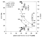
도 1은 공동화 챔버의 다양한 설계를 위한 공동화 영역지도를 도시한다. 공동 발생부를 통한 속도를 공동화 % 및 공동화 수에 관하여 도시한다.
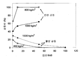
도 2는 비수성 시스템에 대한 공동화 영역을 도시한다. 공동화의 정도와 유형에 따른 액체 밀도의 변화 효과를 도시한다.
도 3은 밀도와 점성의 함수로서 활성 공동화와 안정 공동화에서의 변화를 도시한다. 그리고
도 4는 본 특허에 포함된 실시예들에 대하여 수치로 환산한 공동화 조건들을 도시한다.1 shows a cavitation area map for various designs of cavitation chambers. The speed through the cavitation section is shown in terms of cavitation% and cavitation number.
2 shows the cavitation region for a non-aqueous system. The effect of varying the liquid density on the degree and type of cavitation is shown.
3 shows the change in active cavitation and stable cavitation as a function of density and viscosity. And
FIG. 4 illustrates numerically cavitation conditions for embodiments included in this patent.
본 발명은 물리적 및 화학적 프로세스의 강화를 위하여, 수성 및 비수성 매개물에서 맞춤형 공동화 조건을 달성하기 위한 유체역학적 공동화 반응기 설계에 관한 것이다. 본 발명에서, 신규하고 유용한 동작 관계는 유체역학적 공동화 반응기의 구조적 특징의 효과들과 물리적 및 화학적 프로세스의 강화를 위하여 기결정된 공동화 조건에 도달하기 위하여 유체역학적 공동화 반응기를 설계하기 위한 상기 관계의 사용에 따른 공동화 조건(공동 다이네믹스 및 공동화 강도)에 관한 동작 조건 사이에서 수립된다.The present invention relates to hydrodynamic cavitation reactor designs for achieving tailored cavitation conditions in aqueous and non-aqueous mediators for the enhancement of physical and chemical processes. In the present invention, a novel and useful operating relationship relates to the effects of the structural features of a hydrodynamic cavitation reactor and the use of said relationship for designing a hydrodynamic cavitation reactor to reach predetermined cavitation conditions for enhancing physical and chemical processes. Between operating conditions relating to the cavitation conditions (cavity dynamics and cavitation strength).
유체역학적 공동화 반응기는 공동 발생부, 공동 디버터(diverter) 및 난류 조절부를 포함하고, 공동 발생부/공동 디버터는 다양한 형태와 크기의 유동 조절부이다. 난류 조절부는 공동을 성장, 진동 및/또는 붕괴시켜 원하는 물리화학적 변환에 가장 적합한 진동, 천이 또는 다중-붕괴를 일으키도록 하는 난류의 규모 및 강도를 변경할 수 있는 다양한 기하학적 형태의 부재들을 포함한다. 유동 조절부는 원형이나 구형 또는 삼각형 또는 임의의 기타 적합한 형태를 가진 (뾰족하게 형성되거나 프로파일 형태로 형성된) 오리피스 및/또는 오리피스들 또는 적합한 수렴 또는 발산 각이 있는 수렴 및 발산부가 있는 벤츄리일 수 있다.The hydrodynamic cavitation reactor includes a cavity generator, a cavity diverter and a turbulent flow regulator, and the cavity generator / cavity diverter is a flow regulator of various shapes and sizes. The turbulence controller includes members of various geometric shapes that can vary the magnitude and intensity of the turbulence that causes the cavity to grow, vibrate, and / or collapse to cause the vibration, transition, or multi-disintegration that best suits the desired physicochemical transformation. The flow regulator may be a circular or spherical or triangular or any other suitable shape (pointed or profiled) orifices and / or orifices or a venturi with convergence and divergence with suitable convergence or divergence angles.
따라서 본 발명에 따르면, 먼저, RNG k-ε 난류 모델이 있는 FLUENT 6.2와 같은, 임의의 상업적 CFD 코드를 사용하여 유동 조절부 구성의 다양한 구조적 특징과 동작 조건 범위에 대한 CFD 심뮬레이션이 수행된다. CFD 시뮬레이션에서 얻은 정압, 난류의 운동에너지 및 주파수 등의 유동 정보가 공동 다이네믹스 시뮬레이션에 이용된다. 공동 다이네믹스 시뮬레이션은 레일리-플레셋 방정식(Rayleigh-Plesset equation) 및 토미타-시마 방정식(Tomita-Shima equation) 등의 기포 거동(bubble dynamics) 모델에 기반을 둔다.Thus, according to the present invention, first, CFD simulations for various structural features and operating conditions ranges of the flow control configuration are performed using any commercial CFD code, such as FLUENT 6.2 with RNG k-ε turbulence model. Flow information such as static pressure, turbulent kinetic energy and frequency obtained from CFD simulation is used for the joint dynamics simulation. Joint dynamics simulations are based on bubble dynamics models, such as the Rayleigh-Plesset equation and the Tomita-Shima equation.
시스템에서 최대 압력보다 더 큰 적어도 10배의 순간 압력을 생기게 하는 공동은 공동화 효과를 발생시킬 수 있고 활성 공동으로 명명되고 활성 공동 부분은 다음과 같이 예측된다.A cavity that results in an instantaneous pressure of at least 10 times greater than the maximum pressure in the system can create a cavitation effect and is termed an active cavity and the active cavity portion is predicted as follows.

발생한 공동화 조건은 % 공동화 활동으로 표현되고, 안정한 또는 과도상태의 붕괴 거동 및 단순하지 않은 용해 특성을 보여주는 공동으로 정의된다. % 과도 공동화(transient cavitation)는 총 공동화 활동 중에서 몇 %의 공동이 과도상태의 거동(단일 용적형 팽창 및 수축 사이클에서 붕괴를 겪는다)을 보이는지를 나타내고 비슷하게 % 안정 공동화(단일 용적형 팽창 및 수축 사이클에서 붕괴를 겪는다)는 총 공동화 활동 중에서 몇 %의 공동이 진동하는 거동을 보이는지를 나타낸다.Cavitation conditions that occur are expressed as% cavitation activity and are defined as cavities that exhibit stable or transient decay behavior and non-simple dissolution characteristics. % Transient cavitation indicates how many of the total cavitation activity exhibits transient behavior (explodes in a single volume expansion and contraction cycle) and similarly% stable cavitation (single volume expansion and contraction cycle). Undergo a collapse in), which indicates what percentage of the total cavitation activity exhibits oscillating behavior.
유동 조절부의 구성에서의 변화의 효과 및 유체역학적 공동화 반응기에서 공동화 조건에 따른 동작 조건(표 1)은 유체와 같은 물을 위하여 정의된 공동화 수(도 1)와 같은 정의된 파라미터를 토대로 표시되었다. 도 1의 지도에서 유동 조절부에서 유동 속도는 유동 조절부의 다양한 구조적 특징과 고려된 동작 조건을 나타낸다. 본 발명의 일 형태에서, 표 1 및 도 1에 도시된 바와 같이 기하학적 구조 및 동작 조건의 범위에서 공동화 장치에서 발생하는 공동화의 강도와 유형 사이의 관계가 수립되고 확인된다. 본 발명에 관련된 일 형태에서, 도 1과 유사한 영역지도가 특정의 목적 프로세스에 요구되는 원하는 유형의 공동화를 식별하기 위하여 사용될 것이고 다음에 원하는 그리고 기결정된 프로세스 강화를 달성하기 위하여 반응기가 설계된다.The effect of the change in the configuration of the flow control and the operating conditions according to the cavitation conditions in the hydrodynamic cavitation reactor (Table 1) were expressed based on defined parameters such as the number of cavitations defined for water such as fluid (FIG. 1). The flow velocity in the flow controller in the map of FIG. 1 represents various structural features and operating conditions considered. In one embodiment of the present invention, the relationship between the strength and type of cavitation occurring in the cavitation apparatus in a range of geometries and operating conditions as shown in Table 1 and FIG. 1 is established and confirmed. In one form related to the present invention, an area map similar to FIG. 1 will be used to identify the desired type of cavitation required for a particular desired process and then the reactor is designed to achieve the desired and predetermined process enhancement.
도 1은 특정의 공동화 수(서로 다른 기하학적 구성과 동작 조건으로 도달한 동일한 공동화 수)에 대하여(공동화 수는 공동화의 정도를 말한다), 다양한 물리적 및 화학적 프로세스의 강화를 위하여, 수성 및 비수성 매개물에서의 맞춤형 공동화 조건을 달성하기 위한 유체역학적 공동화 반응기를 설계하는데 이용될 수 있는 유체역학적 공동화 반응기 내부의 공동화 조건(과도 또는 안정 또는 활성)에서 정량화 가능한 차이가 존재한다는 사실을 확립한다. Figure 1 shows, for certain cavitation numbers (the same number of cavities reached with different geometrical configurations and operating conditions) (the cavitation number refers to the degree of cavitation), for the enhancement of various physical and chemical processes, both aqueous and non-aqueous mediators. Establishes the fact that there is a quantifiable difference in cavitation conditions (transient or stable or active) inside a hydrodynamic cavitation reactor that can be used to design a hydrodynamic cavitation reactor to achieve custom cavitation conditions in.
도 1은 유체역학적 공동화 반응기의 구조적 특징 및 유동 조절부의 존재로 인한 유동 속도로 표현되는 동작 조건에 따른 효과를 이끄는데 이용될 수 있다. 첨부된 실시예들에 보이는 바와 같이 본 발명에서 제안된 방법을 사용하여 기하학적 구조와 동작 조건에 의존하는 반응기에서 우세한 변환 유형과 공동화 조건 사이의 분명한 관계가 수립되었고, 변환 뒤에는 상기 물리적 성질/화학적 성질을 촉진하고/거나 강화시킬 수 있다. 따라서 도 1은 특정의 원하는 유형의 변환을 위한 원하는 공동화 조건/공동화의 유형을 얻기 위하여 동작 조건의 기결정된 범위에 대한 공동화 반응기를 설계하는데 이용될 수 있다.1 can be used to drive the effect of operating conditions expressed in the flow rate due to the structural features of the hydrodynamic cavitation reactor and the presence of flow control. As shown in the accompanying examples, a clear relationship between the prevailing transformation type and the cavitation conditions in the reactor depending on geometry and operating conditions was established using the method proposed in the present invention, followed by the physical / chemical properties after the transformation. Can be promoted and / or strengthened. 1 can thus be used to design a cavitation reactor for a predetermined range of operating conditions to obtain the desired cavitation condition / type of cavitation for a particular desired type of conversion.
예를 들면, 공동화 조건에 따라 공동 발생부를 통하는 유동 속도의 효과는 공동화 반응기에서 우세하다. 도 1에서 공동화의 발생(활성 공동화)은 공동화 수의 문턱값인 1.0 이후에만 시작한다. 공동화 수가 더 감소하면 공동화가 현상은 공동화 수가 0.22가 될 때까지 증가한다. 공동화 수가 이보다 더 감소하여도 공동화 현상은 더 이상 증가하지 않는다. 이러한 현상은 주로 주요 유체 성분으로 물이 우세한 수성 시스템에서 발견되었다.For example, depending on the cavitation conditions, the effect of the flow rate through the cavity generator is predominant in the cavitation reactor. The occurrence of cavitation (active cavitation) in FIG. 1 only starts after 1.0, the threshold of cavitation number. If the number of cavities decreases further, the cavitation phenomenon increases until the number of cavities reaches 0.22. Even if the number of cavities decreases further, the cavitation phenomenon no longer increases. This phenomenon has been found mainly in aqueous systems where water predominates as the major fluid component.
도 1에서 공동 발생부에서 액체 속도에서의 증가에 따라 공동화의 과도 형태가 점점 우세하게 되고, 따라서 전체으로 지배하는 공동화 조건에서 우세했던 공동화의 안정한 형태는 감소하게 된다. 그러나, 0.22 또는 그 이하의 공동화 수에 대하여 과도상태의 또는 안정한 공동화 모두 전체 공동화 조건(활성 공동의 %)에서 동일한 종속성을 보여준다.In FIG. 1 the transient form of cavitation becomes increasingly prevalent as the liquid velocity increases in the cavity generator, thus reducing the stable form of cavitation that prevails in the prevailing cavitation conditions. However, both transient or stable cavities for the number of cavitations of 0.22 or less show the same dependency at full cavitation conditions (% of active cavities).
비수성 시스템에 대한 공동화 지도는 도 2에 도시되어 있다. 공동화 매개물에 관련한 비수성 시스템은 물에 대한 것과 아주 다른 밀도, 표면 장력과 점성을 본질적인 특징으로 한다. 본 발명은 다음에 주어진 범위에서 물리화학적 성질을 가지는 액체 또는 액체의 혼합물에 대한 공동화 시스템 설계를 설명한다.The cavitation map for the non-aqueous system is shown in FIG. Non-aqueous systems in connection with cavitation media have inherent features of density, surface tension and viscosity that are very different from those for water. The present invention describes the design of a cavitation system for liquids or mixtures of liquids having physicochemical properties in the following ranges.
밀도 : 800 내지 1500 kg/m3 (물: 1000 kg/m3)Density: 800 to 1500 kg / m 3 (Water: 1000 kg / m 3 )
점성 : 1 내지 100 cP (물: 1 cP)Viscosity: 1 to 100 cP (water: 1 cP)
표면 장력 : 0.01 내지 0.075 N/m (물: 0.072 N/m)Surface tension: 0.01 to 0.075 N / m (water: 0.072 N / m)
증기압 : 30℃에서 300 내지 101325 N/m2 (물: 4200 Pa)Vapor pressure: 300 to 101325 N / m 2 (water: 4200 Pa) at 30 ° C
반응/변환을 위한 매개물은 반응물에 대한 용해도/분산성을 가지고 반응물과 동일한 범위에서 물리화학적 성질을 가지는 임의의 적합한 용매로부터 선택될 수 있다.The medium for reaction / conversion may be selected from any suitable solvent having solubility / dispersibility for the reactants and having physicochemical properties in the same range as the reactants.
액체 밀도(상기 범위인 800 kg/m3 내지 1500kg/m3에서)의 증가에 따라 안정 공동의 정도는 거의 20%까지 감소하는 것으로 보인다(그리고 과도 공동은 증가한다). 활성 공동은 액체 점성이 증가함에 따라 감소하고 100 cP를 넘어설 때 더 이상 존재하지 않게 된다(도 3). 0.01 내지 0.075 N/m의 범위에서의 표면 장력은 공동 수가 1 및 0.37인 극단적인 두 경우에 대하여 공동화의 정도 또는 성질을 변경하는데 중요한 역할을 하지 않는다는 것으로 보였다. 무차원 파라미터 '공동화 수'는 액체의 증기압을 참작하고 따라서 증기압에서의 변화는 직접 공동화 지도에 반영된다.As the liquid density (in the
따라서 유체역학적 공동화 반응기는 물리적 및 화학적 프로세스의 강화를 위한 수성 및 비수성 매개물에서의 공동화 조건을 달성하도록 설계될 수 있고, 공동화 수는 다음의 범위에서 선택된다.The hydrodynamic cavitation reactor can therefore be designed to achieve cavitation conditions in aqueous and non-aqueous vehicles for the strengthening of physical and chemical processes, the cavitation number being selected from the following ranges.
'Ven_ori' 및 'Orifice'에 대한 안정 공동화에 대하여 0.5 내지 1.0,0.5 to 1.0 for stable cavitation for 'Ven_ori' and 'Orifice',
'Ventri', 'NC_ven', 'Ven_step4', 'Stepped2', 'Ori_Ven', 'Stepped4'에 대한 과도 공동화에 대하여 0.22 내지 0.5,0.22 to 0.5 for transient cavitation for 'Ventri', 'NC_ven', 'Ven_step4', 'Stepped2', 'Ori_Ven', and 'Stepped4'
'Ven_ori' 및 'Orifice'에 대한 안정 공동화 및 과도 공동화가 동시에 존재하는 경우에 대하여 0.22 내지 0.5.0.22 to 0.5 for the case where stable cavities and transient cavities for 'Ven_ori' and 'Orifice' are present at the same time.
따라서 본 발명에 따르면 물리적 및 화학적 프로세스의 강화를 위한 수성 및 비수성 매개물에서 공동화 조건을 달성하기 위한 유체역학적 공동화 반응기를 구성하는 방법은:Thus according to the invention a method of constructing a hydrodynamic cavitation reactor for achieving cavitation conditions in aqueous and non-aqueous mediators for the strengthening of physical and chemical processes is:
목적하는 물리적 및/또는 화학적 변환 각각에 대하여 필요한 안정 공동화 및/또는 과도 공동화로부터 선택하고, 과도 공동화는 동종 시스템에서의 화학적 변환을 위하여 선택되고, 안정 공동화는 이종 시스템에서의 화학적 변환과 동종 시스템에서의 물리적 변환을 위하여 선택되고, 안정 및 과도 모두는 이종 시스템에서의 물리적 변환을 위하여 선택되고;Select from the required stable cavities and / or transient cavities for each of the desired physical and / or chemical transformations, the transient cavitations are selected for chemical transformations in homogeneous systems, and the stable cavitations in chemical and homogeneous systems in heterogeneous systems Is selected for the physical transformation of both stable and transient are selected for the physical transformation in the heterogeneous system;
제1 단계에서 선택된 물리적 또는 화학적 변환에 대한 범위로부터 공동화 수를 선택하고;Selecting a cavitation number from a range for the physical or chemical transformation selected in the first step;
선택된 공동화 수에 대한 선택된 공동화 유형에 대하여 활성 공동화를 최대화하도록 영역지도로부터 공동화 챔버의 기하학적 형태(geometry)를 선택하고;Select a geometry of the cavitation chamber from the area map to maximize active cavitation for the selected cavitation type for the selected cavitation number;
상기 선택된 기하학적 형태 내의 공동 발생부 영역을 결정하고, 용적형 유동(volumetric flow)에 대한 상기 공동화 수는 방정식 3을 이용하여 처리되는; 단계를 포함한다.Determining a cavity generation region within the selected geometry, wherein the cavitation number for volumetric flow is processed using

여기에서, 면적은 공동 발생부의 면적(m2), 유동속도는 용적형 유동속도 (m3/s), P2는 공동 발생부에 대한 다운스트림 압력 (Pa), Pv는 동작 온도에서 선택된 변환을 위하여 처리될 액체의 증기압 (Pa), ρ는 액체의 밀도 (kg/m3) 및 Cv는 선택된 공동화 수이다.Where area is the area of the cavity (m 2 ), flow rate is the volumetric flow rate (m 3 / s), P2 is the downstream pressure (Pa) for the cavity, and P v is the selected conversion at operating temperature. The vapor pressure (Pa) of the liquid to be treated, ρ is the density of the liquid (kg / m 3 ) and C v is the selected cavitation number.
공동화 챔버의 기하학적 형태 중 선택된 유형이 오리피스(orifice)일 때, 활성 공동화를 최대화하기 위한 최적화는 구멍의 유동 영역에 대한 구멍의 경계 비율 α가 최대로 되고, 이종 국면에서 구멍의 가장 작은 크기가 가장 큰 경성/ 반 경성 입자보다 적어도 50배 더 크도록, 다수의 구멍의 유동 영역의 합이 상기 면적과 같도록 하는 가장 적은 크기의 다수의 구멍을 선택하여 달성되고, 가장 작은 크기의 구멍은 1mm로 제한된다.When the selected type of cavitation chamber geometry is an orifice, the optimization for maximizing active cavitation is that the boundary ratio α of the hole to the flow area of the hole is maximum, and the smallest size of the hole in the heterogeneous phase is most Achieved by selecting multiple holes of the smallest size such that the sum of the flow zones of the multiple holes is equal to the area so that at least 50 times larger than the large hard / semi-hard particles, the smallest hole is 1 mm. Limited.
만약 이전의 화학적 변환을 가진 유화 단계를 포함하는 액체-액체 이종 시스템에서, 웨버 수(Weber number)가 4.7인 부가적 기준이 선택되면, 웨버 수는 분쇄(breakup)을 저지하는 계면력(interfacial force)에 대한 분쇄의 원인이 되는 관성력의 비율로 정의된다.In a liquid-liquid heterogeneous system that includes an emulsification step with a previous chemical transformation, if an additional criterion is selected with a Weber number of 4.7, the weber number is interfacial force that prevents breakup. It is defined as the ratio of inertial force that causes the grinding to).

여기에서, dE는 에멀젼의 크기, v'는 난류 요동 속도, ρ는 액체의 밀도이고 σ는 계면 표면 장력이고,Where d E is the size of the emulsion, v 'is the turbulent fluctuation rate, ρ is the density of the liquid and σ is the interfacial surface tension,
만약 공동화 챔버의 상기 기하학적 형태의 선택된 유형이 다중 오리피스 공동 발생부라면, 구멍의 거리는 다음 식으로 구한다.If the selected type of geometry of the cavitation chamber is a multiple orifice cavity generator, the distance of the hole is obtained from the following equation.
![]()
![]()
여기에서, dS는 구멍간 거리 (m), dh는 구멍의 최소 치수이고 VJ는 공동 발생부에서 액체의 속도 (m/s)이다.Where d S is the distance between holes (m), d h is the minimum dimension of the hole and V J is the velocity of the liquid (m / s) in the cavity generating part.
도 1, 2 및 4에서와 같이 공동화 챔버, 공동화 수 및 활성, 과도 및 안정 공동화의 퍼센티지를 통하여 액체 또는 슬러리(slury)의 최대 속도를 연관시키는 영역지도는 다음의 단계들로 달성된다:Area maps correlating the maximum velocity of a liquid or slurry through cavitation chambers, cavitation water and percentages of activity, transient and stable cavities as in FIGS. 1, 2 and 4 are achieved by the following steps:
공동 발생부, 유동 및 난류 조절부를 포함하는 공동화 챔버의 기하학적 형태에 대하여, 액체에서의 압력(P), x방향의 속도 성분(u), y방향의 속도성분(v), z방향의 속도성분(w), 난류 운동 에너지(k), 난류 에너지 분산율(ε), 액체 밀도(ρ), 액체상 표면 및 계면 장력(σ), 액체의 점성(μ)과 같은 기본 변수들로 구성된 방정식을 사용한 재료 연속성(material continuity)과 모멘텀 균형, 난류 운동 에너지와 난류 에너지 분산율을 수립하고:With respect to the geometry of the cavitation chamber comprising the cavity generator, the flow and turbulence control, the pressure in the liquid (P), the velocity component (u) in the x direction, the velocity component (v) in the y direction, the velocity component in the z direction material using equations consisting of fundamental variables such as (w), turbulent kinetic energy (k), turbulent energy dispersion (ε), liquid density (ρ), liquid phase and interfacial tension (σ), and liquid viscosity (μ) Establish continuity and momentum balance, turbulent kinetic energy and turbulent energy dispersion:
여기에서 연속 방정식은:Where the continuous equation is:

여기에서, 모멘텀 균형 방정식은:Here, the momentum equilibrium equation is:

여기에서, 난류 운동 에너지 방정식은:Here, the turbulent kinetic energy equation is:

여기에서, 난류 에너지 분산율 방정식은:Here, the turbulent energy dispersion rate equation is:

여기에서, 는 중력가속도 벡터이고 상기 방정식들은 P, k 및 ε를 얻기위하여 수치적으로 구하고;Where is the gravitational acceleration vector and the equations are found numerically to obtain P, k and ε;
공동화 챔버를 통하여 공동이 차지하는 경로의 수 'n'을 획득하고,Obtain the number of paths 'n' the cavity occupies through the cavitation chamber,
여기에서, n은 100보다 매우 크고,Where n is much greater than 100,
여기에서 공동이 차지하는 경로는 라그란지안 방정식(Lagrangian equation)으로 구한다.The path occupied by the cavity is obtained from the Lagrangian equation.

여기에서, UP는 공동 속도, FD(u-uP)는 공동의 단위질량당 항력(drag force)이고, ρP는 공동의 밀도, t는 시간, gx는 x방향에서의 중력가속도(표 1)이다.Where U P is the cavity velocity, F D (uu P ) is the drag force per unit mass of the cavity, ρ P is the density of the cavity, t is time, and g x is the gravitational acceleration in the x direction (Table 1).
여기에서, 라그란지안 방정식은 공동의 시간 의존 좌표를 획득하기 위하여 수치적으로 구한다.Here, the Lagrangian equation is found numerically to obtain the joint time dependent coordinates.
여기에서, PBulk, k 및 ε는 라그란지안 방정식 (8)에서 구한 이들 좌표에서의 균형 해에서 구한다.Here, P Bulk , k and ε are obtained from a balanced solution at these coordinates obtained from the Lagrangian equation (8).
다음의 관계로부터 압력 진폭(Pamp), 압력 주파수(f) 및 공동에 의하여 감지된 순간 압력(P∞) 값을 획득하고:Obtain the value of pressure amplitude (P amp ), pressure frequency (f) and instantaneous pressure (P ∞ ) detected by the cavity from the following relationship:
![]()

![]()
![]()
![]()
P∞, Pamp, f에 대한 상기 데이터를 사용하여 공동 거동 모델로부터 공동 거동 즉, 시간의 함수로서 공동의 반경을 획득하고, 여기에서, 공동 거동 모델은 예를 들면 다음의 방정식의 레일리-플레셋으로 일반적으로 알려진다.The above data for P ∞ , P amp , f are used to obtain the cavity behavior from the cavity behavior model, ie the radius of the cavity as a function of time, where the cavity behavior model is for example the Rayleigh-Ple. Commonly known as three.

여기에서, t는 시간, R은 임의의 순간에서의 공동의 반경, σ는 액체의 표면 장력, μ는 액체의 점성, PB는 거품 내부의 압력이다.Where t is time, R is the radius of the cavity at any moment, σ is the surface tension of the liquid, μ is the viscosity of the liquid, and P B is the pressure inside the bubble.
다음의 기준을 사용한 활성, 안정 및 과도 공동화로 공동을 분류하고,Classify cavities into active, stable and transient cavities using the following criteria,
여기에서, 공동 내부압력이 공동화 챔버 유입구 압력의 10배 이상이면 공동은 활성이고,Wherein the cavity is active if the cavity internal pressure is at least 10 times the cavitation chamber inlet pressure,
여기에서, 최종 압력이, 공동의 생존 동안에, 공동 내 최대 압력과 같지 않으면 활성 공동은 안정 공동이고,Wherein the active cavity is a stable cavity if the final pressure is not equal to the maximum pressure in the cavity during the survival of the cavity,
여기에서, 최종 압력이 공동 내 최대 압력과 같다면 활성 공동은 과도 공동이고;Wherein the active cavity is a transient cavity if the final pressure is equal to the maximum pressure in the cavity;
주어진 속도에 대하여 공동화 수, 공동화 챔버의 선택된 기하학적 형태(형태나 크기)를 계산하고;Calculate the number of cavities, the selected geometry (shape or size) of the cavitation chamber for a given speed;
활성 공동화의 퍼센티지는 활성 공동의 수/공동의 총수×100으로;The percentage of active cavities is the number of active cavities / total number of cavities × 100;
안정 공동화의 퍼센티지는 안정 공동의 수/활성 공동의 총수×100으로;The percentage of stable cavities is the number of stable cavities / total number of active cavities × 100;
과도 공동화의 퍼센티지는 과도 공동의 수/활성 공동의 총수×100으로; 계산한다.The percentage of transient cavitation is the total number of transient cavities / active cavities × 100; Calculate
상기 방법은 다음과 같은 공동화 챔버의 다양한 기하학적 형태를 형성하기 위하여 사용되었다.The method was used to form various geometries of the cavitation chamber as follows.
i) 'Venturi'는 α값을 최대로 하는 원형 또는 비원형(non circular) 공동화 챔버에서 최소 단면영역의 일부 또는 전체에 해당하는 공동 발생부; 및i) 'Venturi' is a cavity generation part corresponding to part or all of the minimum cross-sectional area in a circular or non circular cavitation chamber with the maximum value of α; And
공동 발생부로 명명되는 최소 단면영역의 업스트림에서 52-55°의 전체 평균 각이 있는 완만한 수렴부와 공동 발생부의 다운스트림에서 20-25°의 전체 평균 각을 갖는 완만한 발산부에 해당하는 유동 조절부;를 포함하고,Flows corresponding to a gentle converging part with an overall average angle of 52-55 ° upstream of the minimum cross-sectional area, called the cavity section, and a gentle diverging part with an overall average angle of 20-25 ° downstream of the cavity section. It includes;
상기 'Venturi'는 유동 방향에 순차적으로 배치된 3개의 동축부로 구성된다.'Venturi' is composed of three coaxially arranged sequentially in the flow direction.
수렴부는 그 축이 직선이고,The convergence part is straight in axis
그 단면영역이 그 길이 전체에서 원형이고,The cross-sectional area is circular throughout its length,
그 도관(conduit)의 직경이 유동 방향에서 m당 0.93 내지 1.06m의 비율로 감소하고,The diameter of the conduit decreases at a rate of 0.93 to 1.06 m per meter in the flow direction,
단면영역이 스로트부(Throat section)의 단면영역과 같을 때 종결한다.Terminate when the cross section is equal to the cross section of the throat section.
스로트부는 그 축이 직선이고,The throat part is straight in axis,
그 도관의 단면영역이 원형이고,The cross-sectional area of the conduit is circular,
그 단면영역이 일정하고 방정식 (3)으로부터 구해지고,Its cross-sectional area is constant and is obtained from equation (3),
그 영역의 길이가 그 직경의 반과 같다.The length of the area is equal to half its diameter.
발산부는 그 도관의 축이 직선이고,The diverging part is straight in the axis of the conduit,
그 도관의 단면영역이 그 길이 전체에서 원형이고,The cross-sectional area of the conduit is circular throughout its length,
그 도관의 직경이 유동 방향에서 m당 0.35 내지 0.44m의 비율로 증가하고,The diameter of the conduit increases at a rate of 0.35 to 0.44 m per m in the flow direction,
그 길이가 수렴부의 길이의 2.64배와 같다.The length is equal to 2.64 times the length of the convergence part.
ii) 'Ven_step4'는 α값을 최대로 하는 원형 또는 비원형(non circular) 공동화 챔버에서 최소 단면영역의 일부 또는 전체에 해당하는 공동 발생부; ii) 'Ven_step4' is a cavity generation part corresponding to part or all of the minimum cross-sectional area in a circular or non circular cavitation chamber with the maximum value of α;
유동에 평행한 더 긴 축을 따라 배열된 공동 발생부의 최대 치수와 같은 길이(폭)의 다중 영역이 있는 상기 공동 발생부의 다운스트림이고 함께 도관을 형성하는 난류 조절부;A turbulence regulator downstream of said cavity generator with multiple regions of length (width) equal to the maximum dimension of the cavity generator arranged along a longer axis parallel to the flow and forming conduits together;
공동 발생부로 명명되는 최소 단면영역의 업스트림에서 52-55°의 전체 평균 각이 있는 완만한 수렴부를 포함하고,Including a gentle convergence with an overall mean angle of 52-55 ° upstream of the minimum cross-sectional area, called the cavity generator,
상기 'Ven_step4'는 유동 방향에 순차적으로 배치된 3개의 동축부로 구성된다.'Ven_step4' is composed of three coaxially arranged in sequence in the flow direction.
수렴부는 그 축이 직선이고,The convergence part is straight in axis
그 단면영역이 그 길이 전체에서 원형이고,The cross-sectional area is circular throughout its length,
그 도관의 직경이 유동 방향에서 m당 0.93 내지 1.06m의 비율로 감소하고,The diameter of the conduit decreases at a rate of 0.93 to 1.06 m per meter in the flow direction,
그 단면영역이 스로트부의 단면영역과 같아질 때 종결한다.It terminates when the cross-sectional area becomes equal to the cross-sectional area of the throat part.
스로트부는 그 축이 직선이고,The throat part is straight in axis,
그 도관의 단면영역이 원형이고,The cross-sectional area of the conduit is circular,
그 단면영역이 상수이고 방정식 (3)으로부터 구해지고,Its cross-sectional area is constant and is obtained from equation (3),
그 영역의 길이가 그 직경의 반이다.The length of the area is half of its diameter.
발산부는 다중 오리피스를 포함하고,The diverging part comprises multiple orifices,
각 순차적 오리피스판이 이전 오리피스판과 접촉하고,Each sequential orifice plate contacts the previous orifice plate,
각 오리피스판은 단지 하나의 구멍이 있고,Each orifice plate has only one hole,
오리피스판에 있는 모든 구멍은 원형이고 스로트부의 축과 동축이고,All the holes in the orifice plate are circular and coaxial with the axis of the throat part,
그 각 오리피스판의 두께는 스로트부의 길이의 두 배이고,The thickness of each orifice plate is twice the length of the throat part,
순차적 오리피스판의 직경은 각 오리피스판의 두께의 0.35 - 0.44배 증가하고,The diameter of the sequential orifice plates increases 0.35-0.44 times the thickness of each orifice plate,
이 영역의 길이는 수렴부의 길이의 2.64배와 같다.The length of this region is equal to 2.64 times the length of the convergence section.
iii) 'Stepped2'는 α값을 최대로 하는 원형 또는 비원형(non circular) 공동화 챔버에서 최소 단면영역의 일부 또는 전체에 해당하는 공동 발생부; iii) 'Stepped2' is a cavity generating part corresponding to part or all of the minimum cross-sectional area in a circular or non circular cavitation chamber with the maximum value of α;
유동 영역의 증가와 함께 유동에 평행한 더 긴 축을 따라 배열된 공동 발생부의 최대 치수의 반과 같은 길이(폭)의 영역들이 있는 상기 공동 발생부의 업스트림 및 다운스트림이고 함께 업스트림에서 52 - 56° 및 다운스트림에서 다시 20 - 25°의 전체 평균 각을 갖는 증가하는 유동 영역의 도관을 형성하는 난류 조절부;52-56 ° up and downstream of the cavity, together with upstream and downstream regions of length (width) equal to half the maximum dimension of the cavity, arranged along the longer axis parallel to the flow with increasing flow area. A turbulence regulator forming a conduit of increasing flow region with a total average angle of 20-25 ° in the stream again;
상기 'Stepped2'는 유동 방향에 순차적으로 배치된 3개의 동축부로 구성된다.'Stepped2' is composed of three coaxially arranged sequentially in the flow direction.
수렴부는 다중 오리피스를 포함하고,Converging part includes multiple orifices,
각 순차적 오리피스판은 이전 오리피스판과 접촉하고,Each sequential orifice plate contacts the previous orifice plate,
각 오리피스판은 단지 하나의 홀이 있고,Each orifice plate has only one hole,
오리피스판에 있는 모든 구멍은 원형이고 스로트부의 축과 동축이고,All the holes in the orifice plate are circular and coaxial with the axis of the throat part,
그 각 오리피스판의 두께는 스로트부의 길이와 같고,The thickness of each orifice plate is equal to the length of the throat part,
그 순차적 오리피스판에 있는 구멍의 직경은 각 오리피스판의 두께의 0.93 - 1.06배 감소하고,The diameter of the holes in the sequential orifice plates is reduced by 0.93-1.06 times the thickness of each orifice plate,
그 구멍 영역이 스로트부의 단면영역과 같을 때 종결한다.It terminates when the hole area is equal to the cross-sectional area of the throat part.
스로트부는 그 축이 직선이고,The throat part is straight in axis,
그 도관의 단면영역이 원형이고,The cross-sectional area of the conduit is circular,
그 단면영역이 상수이고 방정식 (3)으로부터 구해지고,Its cross-sectional area is constant and is obtained from equation (3),
스로트부의 길이는 그 직경의 반이다.The length of the throat is half of its diameter.
발산부는 다중 오리피스를 포함하고,The diverging part comprises multiple orifices,
각 순차적 오리피스판은 이전 오리피스판과 접촉하고,Each sequential orifice plate contacts the previous orifice plate,
각 오리피스판은 단지 하나의 구멍이 있고,Each orifice plate has only one hole,
오리피스판에 있는 모든 구멍은 원형이고 스로트부의 축과 동축이고,All the holes in the orifice plate are circular and coaxial with the axis of the throat part,
그 각 오리피스판의 두께는 스로트부의 길이와 같고,The thickness of each orifice plate is equal to the length of the throat part,
순차적 오리피스판의 직경은 각 오리피스판의 두께보다 0.35 - 0.44배 증가하고,The diameter of the sequential orifice plates increases 0.35-0.44 times the thickness of each orifice plate,
이 영역의 길이는 수렴부의 길이의 2.64배와 같다.The length of this region is equal to 2.64 times the length of the convergence section.
iv) 'Ori_Ven'은 α값을 최대로 하는 원형 또는 비원형(non circular) 공동화 챔버에서 최소 단면영역의 일부 또는 전체에 해당하는 공동 발생부; 및iv) 'Ori_Ven' is a cavity generation part corresponding to part or all of the minimum cross-sectional area in a circular or non circular cavitation chamber for maximizing α value; And
공동 발생부의 다운스트림에서 20-25°의 전체 평균 각을 갖는 완만한 발산부에 해당하는 유동 조절부;를 포함하고,A flow regulator corresponding to a gentle divergence having an overall average angle of 20-25 ° downstream of the cavity generator;
상기 'Ori_Ven'은 유동 방향에 순차적으로 배치된 두 개의 동축부로 구성된다.'Ori_Ven' is composed of two coaxial parts sequentially arranged in the flow direction.
스로트부는 그 축이 직선이고,The throat part is straight in axis,
그 도관의 단면영역이 원형이고,The cross-sectional area of the conduit is circular,
그 단면영역은 상수이고 방정식 (3)으로부터 구해지고,Its cross-sectional area is constant and is obtained from equation (3),
그 영역의 길이는 그 직경의 반과 같다.The length of the area is equal to half its diameter.
발산부는 그 도관의 축이 직선이고,The diverging part is straight in the axis of the conduit,
그 도관의 단면영역이 그 길이 전체에서 원형이고,The cross-sectional area of the conduit is circular throughout its length,
그 도관의 직경이 유동 방향에서 m당 0.35 내지 0.44m의 비율로 증가하고,The diameter of the conduit increases at a rate of 0.35 to 0.44 m per m in the flow direction,
그 길이가 액체의 유속 (m3/s) / 스로트부의 면적 (m2) * 0.001m이다.Its length is liquid flow rate (m 3 / s) / area of the throat part (m 2 ) * 0.001m.
v) 'Stepped4'는 α값을 최대로 하는 원형 또는 비원형(non circular) 공동화 챔버에서 최소 단면영역의 일부 또는 전체에 해당하는 공동 발생부;v) 'Stepped4' is a cavity generating part corresponding to part or all of the minimum cross-sectional area in a circular or non circular cavitation chamber with the maximum value of α;
각각 20 - 25°및 52 - 56°의 전체 평균 각을 갖는 유동 영역에 대하여 각각 감소 및 증가하는 방식으로 배열된 상기 공동 발생부의 최대 치수와 같은 길이(폭)의 다중 영역들의 집합으로서 상기 공동 발생부의 업스트림 및 다운스트림에 있는 난류 조절부;를 포함하고,Cavitation as a collection of multiple zones of the same length (width) as the maximum dimensions of the cavitation section arranged in a decreasing and increasing manner, respectively, for flow regions having an overall mean angle of 20-25 ° and 52-56 °, respectively. It includes; turbulence control unit upstream and downstream of the negative,
상기 'Stepped4'는 유동 방향에 순차적으로 배치된 3개의 동축부로 구성된다.'Stepped4' is composed of three coaxially arranged sequentially in the flow direction.
수렴부는 다중 오리피스를 포함하고,Converging part includes multiple orifices,
각 순차적 오리피스판은 그 이전 오리피스판과 접촉하고,Each sequential orifice plate contacts the previous orifice plate,
각 오리피스판은 단지 하나의 구멍이 있고,Each orifice plate has only one hole,
오리피스판에 있는 모든 구멍은 원형이고 스로트부의 축과 동축이고,All the holes in the orifice plate are circular and coaxial with the axis of the throat part,
그 각 오리피스판의 두께는 스로트부의 길이의 두 배이고,The thickness of each orifice plate is twice the length of the throat part,
그 순차적 오리피스판에 있는 구멍의 직경은 각 오리피스판의 0.93 - 1.06배 감소하고,The diameter of the holes in that sequential orifice plate is reduced by 0.93-1.06 times that of each orifice plate,
그 오리피스판에 있는 구멍 영역이 스로트부의 단면영역과 같을 때 종결한다.It terminates when the hole area | region in the orifice plate is equal to the cross-sectional area | region of a throat part.
스로프부는 그 축이 직선이고,The slope portion is straight in axis,
그 도관의 단면영역이 원형이고,The cross-sectional area of the conduit is circular,
그 단면영역이 상수이고 방정식 (3)으로부터 구해지고,Its cross-sectional area is constant and is obtained from equation (3),
스로트부의 길이는 그 직경의 반이다.The length of the throat is half of its diameter.
발산부는 다중 오리피스를 포함하고,The diverging part comprises multiple orifices,
각 순차적 오리피스판은 그 이전 오리피스판과 접촉하고,Each sequential orifice plate contacts the previous orifice plate,
각 오리피스판은 단지 하나의 구멍이 있고,Each orifice plate has only one hole,
오리피스판에 있는 모든 구멍은 원형이고 스로트부의 축과 동축이고,All the holes in the orifice plate are circular and coaxial with the axis of the throat part,
그 각 오리피스판의 두께는 스로트부의 길이의 두 배이고,The thickness of each orifice plate is twice the length of the throat part,
순차적 오리피스판의 직경은 각 오리피스판의 두께의 0.35 - 0.44배 증가하고,The diameter of the sequential orifice plates increases 0.35-0.44 times the thickness of each orifice plate,
이 영역의 길이는 수렴부의 길이의 2.64배와 같다.The length of this region is equal to 2.64 times the length of the convergence section.
vi) 'Ven_Ori'는 α값을 최대로 하는 임의의 형태의 공동화 챔버에서 최소 단면영역의 일부에 해당하는 공동 발생부;vi) 'Ven_Ori' is a cavity generating part corresponding to a part of the minimum cross-sectional area in the cavitation chamber of any type to maximize the value of α;
공동 발생부의 업스트림로 52 - 56°의 각을 갖는 완만한 수렴부에 해당하는 유동 조절부;를 포함하고,A flow regulator corresponding to a gentle converging portion having an angle of 52-56 ° upstream of the cavity generator;
상기 'Ven_Ori'는 유동 방향에 순차적으로 배치된 두 개의 동축부로 구성된다.The 'Ven_Ori' is composed of two coaxial parts sequentially arranged in the flow direction.
수렴부는 그 축이 직선이고,The convergence part is straight in axis
그 단면영역이 그 길이 전체에서 원형이고,The cross-sectional area is circular throughout its length,
그 도관의 직경이 유동 방향에서 m당 0.93 내지 1.06m의 비율로 감소하고,The diameter of the conduit decreases at a rate of 0.93 to 1.06 m per meter in the flow direction,
그 단면영역이 스로트부의 단면영역과 같을 때 종결한다.It terminates when the cross-sectional area is the same as the cross-sectional area of a throat part.
스로트부는 그 축이 직선이고,The throat part is straight in axis,
그 도관의 단면영역이 원형이고,The cross-sectional area of the conduit is circular,
그 단면영역이 상수이고 방정식 (3)으로부터 구해지고,Its cross-sectional area is constant and is obtained from equation (3),
그 영역의 길이가 그 직경의 반과 같다.The length of the area is equal to half its diameter.
vii) 'Orifice'는 α값을 최대로 하는 원형 또는 비원형(non circular) 공동화 챔버에서 최소 단면영역의 일부 또는 전체에 해당하는 공동 발생부를 포함하고,vii) 'Orifice' includes a cavity generating part or all of the minimum cross-sectional area in a circular or non circular cavitation chamber with a maximum of α,
상기 'Orifice'는 스로트부로 구성되고,'Orifice' is composed of a throat part,
그 축이 직선이고,The axis is a straight line,
그 도관의 단면영역이 원형이고,The cross-sectional area of the conduit is circular,
그 단면영역이 상수이고 방정식 (3)으로부터 구해지고,Its cross-sectional area is constant and is obtained from equation (3),
그 영역의 길이가 그 직경의 반과 같다.The length of the area is equal to half its diameter.
viii) 'NC_Ven'은 α값을 최대로 하는 원형 또는 비원형(non circular) 공동화 챔버에서 최소 단면영역의 일부 또는 전체에 해당하는 공동 발생부;viii) 'NC_Ven' is a cavity generating part corresponding to part or all of the minimum cross-sectional area in a circular or non circular cavitation chamber with the maximum value of α;
공동 발생부의 업스트림에서 52-55°의 전체 평균 각이 있는 완만한 수렴부와 공동 발생부의 다운스트림에서 20-25°의 전체 평균 각을 갖는 완만한 발산부에 해당하고, 상기 공동 발생부의 다운스트림에서 동일하거나 다르지만 비원형인 형태를 유지하는 유동 조절부;를 포함한다.Corresponding to a gentle convergence with an overall average angle of 52-55 ° upstream of the cavity generator and a gentle divergence with an overall average angle of 20-25 ° downstream of the cavity generator, downstream of the cavity generator. Includes; flow control unit to maintain the same or different but non-circular in shape.
본 발명은 박테리아 파괴에 의한 물 살균, 로다민 열화, 톨루엔 산화, 냉각탑의 생물학적 오염(biofouling), 지방산의 에스테르화 및 용해가능한 탄소의 방출과 같은 특정 물리적, 화학적 또는 생물학적 변환에서 프로세스 강화를 포함하는 유체역학적 공동화를 이용하기 위한 반응기 설계에 대한 제한적이지 않은 실시예들과 함께 예시된다. 기하학적 형태, 에너지 소비, 공동화 최적과 관련된 실시예들 또한 포함된다.
The present invention includes process enhancement in certain physical, chemical or biological transformations, such as water sterilization by bacterial destruction, rhodamine degradation, toluene oxidation, biofouling of cooling towers, esterification of fatty acids and release of soluble carbon. Illustrated with non-limiting embodiments of reactor designs for using hydrodynamic cavitation. Embodiments related to geometry, energy consumption, cavitation optimization are also included.
실시예Example
다양한 변환에 대한 설계 특징, 동작 조건, 공동화 조건 및 이들 공동화 조건의 효과가 표 2a에 기재되어 있다. 이들 공동화 장치들(표 2a에 보이는 바와 같이 먼저 시뮬레이션한 서로 다른 구성의 오리피스판)이 유체역학적 공동화 반응기의 설계를 위하여 제조되고 실험으로 검사되어 도 1의 결과를 보여주었다.Design features, operating conditions, cavitation conditions, and the effects of these cavitation conditions on various transformations are described in Table 2a. These cavitation devices (orifice plates of different configurations, first simulated as shown in Table 2a) were prepared for the design of the hydrodynamic cavitation reactor and experimentally examined to show the results of FIG. 1.
도 1은 특정 프로세스 강화를 수행하기 위한 반응기를 설계하기 위하여 확인되고 이용되었고, 상술한 바와 같이 도 1의 응용예를 예시한다.
1 has been identified and used to design a reactor for performing certain process enhancements, and illustrates the application of FIG. 1 as described above.
실시예Example 1 One
공동화 Cavitation 챔버의Of chamber 기하학적 형태 분석 Geometric shape analysis
공동화 챔버의 다양한 기하학적 형태는 대표적 액체 유동속도인 2.5×10⁻⁴m3/s 및 공동화 수 0.5를 처리하기 위하여 설계되었다. 상기 파라미터들은 예시만을 목적으로 선택된 것이지만 본 방법과 이에 의하여 얻어진 설계는 이들 동작 및 설계 파라미터의 범위에서 사용될 수 있다. 공동 발생부의 면적은 상기 언급한 대표 액체 유동속도 (2.5×10⁻⁴m3/s) 및 1.26×10⁻⁵m2로서 선택된 공동화 수(0.5)에 대한 방정식 (3)으로부터 계산되었다. 본 방법에 기초하여 공동화 장치의 몇 가지 형태가 공동화 거동을 위하여 획득되고 분석되었다.Various geometries of the cavitation chamber were designed to handle the typical liquid flow rates of 2.5 × 10 −4 m 3 / s and cavitation water of 0.5. The above parameters are chosen for illustrative purposes only, but the method and the design obtained thereby may be used within a range of these operating and design parameters. The area of the cavity generating part was calculated from equation (3) for the cavitation number (0.5) selected as the above-mentioned representative liquid flow rate (2.5 × 10 −4 m 3 / s) and 1.26 × 10 −5 m 2 . Based on the method several types of cavitation devices were obtained and analyzed for cavitation behavior.
다양한 설계를 위하여 예측된 압력강하가 표 3에 주어진다. 주어진 액체 유동속도에 대하여, 가장 높은 압력강하(3.15 atm)가 오리피스 내에 일어날 때 가장 낮은 압력강하(0.475 atm)가 벤츄리 내에 일어남을 알 수 있다. 'ori_ven'의 경우 압력강하는 'ven_ori'에서의 압력강하(2.13 atm)보다 더 낮다(1.55 atm).The estimated pressure drops for various designs are given in Table 3. It can be seen that for a given liquid flow rate, the lowest pressure drop (0.475 atm) occurs in the venturi when the highest pressure drop (3.15 atm) occurs in the orifice. In the case of 'ori_ven', the pressure drop is lower than the pressure drop in 'ven_ori' (2.13 atm) (1.55 atm).
표 3은 다양한 설계를 위하여 주입된 총 공동 중 활성 공동의 %를 보여준다. 활성 공동의 %가 다운스트림부가 오리피스에서와 같은 급격한 팽창 대신에 발산(venturi/stepped)할 때 더 높다는 것을 알 수 있다.Table 3 shows the percentage of active cavities out of the total cavities injected for the various designs. It can be seen that the percentage of active cavities is higher when the downstream portion is venturi / stepped instead of abrupt expansion as in the orifice.
표 3은 몇 가지 설계에서 생성된 활성 및 과도 공동의 정도를 자세하게 보여준다. 표 3은 본 발명으로부터 획득되는, 단위압력강하당 활성 공동의 퍼센티지 및 단위압력강하당 과도 공동의 퍼센티지를 나타낸다. 본 방법을 사용하면 공동화 장치의 공동화 거동을 정량화할 수 있고 주어진 물리화학적 변환에 대하여 최적화된 기하학적 형태와 동작 파라미터를 이끌어 낼 수 있다.Table 3 details the degree of activity and transient cavities produced in several designs. Table 3 shows the percentage of active cavities per unit pressure drop and the percentage of transient cavities per unit pressure drop obtained from the present invention. Using this method, we can quantify the cavitation behavior of the cavitation device and derive the optimized geometric shape and operating parameters for a given physicochemical transformation.
다양한 설계에 대한 공동화 영역지도가 본 방법에 기초하여 생성되고, 도 1에 도시된다. 점선은 안정 공동의 정도를 나타내고 실선은 활성 공동의 정도를 나타낸다. 공동화 영역지도를 사용하여 임의의 공동화 인자의 설계를 위한 동작 파라미터(공동화 수)가 결정될 수 있다. 비록 도 1이 물질로서 물을 위한 공동화 영역지도를 도시하고 있지만 이미 앞에서 도 2를 참조하여 설명한 바와 같이, 밀도, 점성, 표면 장력 및 증기압에서 아주 다른 액체에 대한 것으로 변경할 수 있다.
Cavitation area maps for various designs are generated based on the present method and shown in FIG. 1. The dashed line represents the degree of stable cavity and the solid line represents the degree of active cavity. An operating parameter (number of cavitations) for the design of any cavitation factor may be determined using the cavitation area map. Although FIG. 1 shows a cavitation area map for water as material, it can be changed to that for a very different liquid in density, viscosity, surface tension and vapor pressure, as previously described with reference to FIG. 2.
실시예Example 2 2
유체역학적 공동화를 이용한 음용수 살균/ 박테리아 파괴Drinking Water Sterilization / Bacteria Destruction Using Hydrodynamic Cavitation
물 살균, 폐수처리, 생물학적 오염 방지, 효소 회복 등과 같은 몇 가지 응용을 위하여 미생물 세포 파괴가 수행된다. 미생물 세포는 공동이 미생물 세포 근방에서 붕괴(과도 공동화)되거나 급격한 용적형 진동(안정 공동화)을 겪을 때 파괴된다. 과도 또는 안정 공동화에 의하여 생성되어 부가된 스트레스가 세포강도보다 훨씬 더 크다면, 세포벽은 파괴된다. 따라서 양쪽 형태의 공동화 모두 세포 파괴의 정도를 돕게 되는 것이다. 미생물 살균은 이종 시스템에서 공동화의 물리적 효과에 기인하여 발생한다. 따라서 안정 및 과도 공동화 모두 미생물 세포 파괴를 위하여 최적화될 수 있다. 도 1에 도시된 영역지도로부터, 오리피스에 대하여 가장 높은 안정 공동화를 제공하는 0.22 내지 0.5의 범위에서 공동화 수가 선택된다. 상기 범위에서 선택된 0.28의 공동화 수에 대하여, 6.73×10⁻⁴m3/s의 유동속도에 대한 오리피스 내 구멍의 면적은 방정식 (3)으로부터 2.55×10⁻⁵m2으로 계산되었다. 이 구멍 영역은 직경 5.70mm의 단일 구멍에 해당한다. 선택된 공동화 챔버가 오리피스판이기 때문에, α값(개구 영역에 대한 구멍 직경의 비)을 최대로 할 필요가 있다. 가장 높은 α값을 제공하는 1mm의 한계값이 선택된다. 따라서 오리피스판은 1mm 직경의 33개의 구멍을 가지도록 설계되고 제조되었다. 서로 다른 유입압에서 공동화 인자(오리피스판)의 성능 특성은 표 2b에 보인다. 표 2a로부터 공동화의 강도(활성 공동의 %)가 유입압의 증가에 따라 증가하고 이에 따라 살균의 퍼센티지도 또한 증가함을 알 수 있다. 유입압의 4배 증가(1.72 bar에서 5.77 bar로)는 활성 공동화에서 13배를 증가시키고, 따라서 살균에서는 50% 증가시킨다. 이미 앞에서 설명한 바와 같이, 공동화의 형태(과도 또는 안정)는 물을 살균하는데 매우 큰 효과를 가진다. 낮은 액체 속도(~14m/s(w-1))에서 수행된 물 살균에 관한 연구는 비록 아주 적은 과도 공동이 존재하더라도 진동하는(안정) 공동으로부터 약 60%의 상당한 살균결과를 가져온다는 것을 보여주었다. 또한, 과도 공동화의 총량이 53% 증가함에 따라 살균이 50% 증가한다는 것을 알 수 있었고, 이는 과도 공동화의 효과가 살균결과와 거의 1대1로 연관되어 있음을 나타낸다. 따라서 도 1 및 4에 기반한 안정 공동화 또는 과도 공동화에서 공동화 장치를 설계하고 동작함으로써, 요구되는 효과들이 물리적 변환과 관련하여 달성된다. 따라서 이종 시스템에서 미생물 세포 파괴를 위한 맞춤형 공동화 반응기가 안정 및 과도 공동화에서 동작하도록 설계되었고, 여기에서, 공동화 수는 6.73×10⁻⁴m3/s에 대하여 0.22에서 0.5, 바람직하게는 0.28까지의 범위에서 선택되고, 오리피스 내 구멍의 면적은 직경 5.70mm의 단일 구멍에 해당하는 2.55×10⁻⁵m2이고, 가장 작은 구멍의 직경은 α값을 구멍의 직경이 1mm일 때인 한계값까지 최대화하도록 선택되고, 따라서 요구되는 총 유동 면적을 달성하기 위하여 구멍이 33개에 달하고 86%의 세포 파괴를 가져오는 46%의 안정 공동화의 정도가 되는 39%의 활성 공동화가 발생한다.
Microbial cell destruction is performed for several applications, such as water sterilization, wastewater treatment, biological contamination prevention, enzyme recovery, and the like. Microbial cells are destroyed when the cavities collapse (over-cavitation) or undergo rapid volumetric vibrations (stable cavitation) near the microbial cells. If the added stress generated by excessive or stable cavitation is much greater than the cell strength, the cell wall is destroyed. Thus, both forms of cavitation help the degree of cell destruction. Microbial sterilization occurs due to the physical effects of cavitation in heterogeneous systems. Thus both stability and transient cavitation can be optimized for microbial cell destruction. From the area map shown in FIG. 1, the number of cavities is selected in the range of 0.22 to 0.5, which provides the highest stable cavitation for the orifice. For a cavitation number of 0.28 selected in the above range, the area of the hole in the orifice for a flow rate of 6.73 × 10 −4 m 3 / s was calculated from equation (3) as 2.55 × 10 −5 m 2 . This hole area corresponds to a single hole of 5.70 mm in diameter. Since the selected cavitation chamber is an orifice plate, it is necessary to maximize the α value (ratio of hole diameter to opening area). The limit value of 1 mm is chosen which gives the highest α value. Thus, the orifice plate was designed and manufactured to have 33 holes of 1 mm diameter. The performance characteristics of the cavitation factor (orifice plate) at different inlet pressures are shown in Table 2b. From Table 2a it can be seen that the intensity of cavitation (% of active cavities) increases with increasing inlet pressure and thus the percentage of sterilization also increases. A four-fold increase in inlet pressure (from 1.72 bar to 5.77 bar) increases 13 times in active cavitation and thus 50% in sterilization. As already explained above, the form of cavitation (transient or stable) has a very large effect on the sterilization of water. Studies on water sterilization performed at low liquid velocities (~ 14 m / s (w-1)) show that, even in the presence of very few transient cavities, significant 60% sterilization results are obtained from oscillating (stable) cavities. gave. In addition, it can be seen that the sterilization is increased by 50% as the total amount of transient cavitation increases by 53%, indicating that the effect of transient cavitation is almost one-to-one with the sterilization result. Thus, by designing and operating a cavitation device in stable cavitation or transient cavitation based on Figs. 1 and 4, the desired effects are achieved with respect to physical transformation. Thus, custom cavitation reactors for microbial cell destruction in heterogeneous systems are designed to operate at stable and transient cavitations, where cavitation numbers range from 0.22 to 0.5, preferably 0.28 for 6.73 × 10 −4 m 3 / s. Selected from the range, the area of the hole in the orifice is 2.55 × 10 -5 m 2 , which corresponds to a single hole of 5.70 mm diameter, and the diameter of the smallest hole is such that the value of α is maximized to the limit when the diameter of the hole is 1 mm. 39% active cavitation occurs, resulting in a degree of 46% stable cavitation resulting in 33 holes and 86% cell destruction to achieve the required total flow area.
실시예Example 3 3
유체역학적 공동화를 사용한 Using hydrodynamic cavitation 로다민Rhodamine 열화 Deterioration
로다민은 직물 산업에서 일반적으로 사용되는 방향성 아민 염료이다. 로다민은 오염물질을 포함하는 폐기물 스트림을 탈색하는데 필요하다. 공동화는 이러한 분자의 착색(chromophore)을 깨트리고 따라서 폐기물의 기체유출물(effluent) 스트림을 탈색한다. 이는 동종 시스템에서의 물리적 변환이다. 따라서 이러한 변환을 위하여 안정 공동화는 최대가 되어야 한다. 도 1에 도시된 영역지도에서, 공동화 수는 오리피스에 대하여 가장 높은 안정 공동화를 제공하는 범위인 0.5 내지 1.0의 범위에 있어야 한다. 선택된 공동화 수의 범위로부터 공동화 수 0.78이 선택되고 오리피스의 개구부 영역은 방정식 (3)으로부터 4.08×10⁻⁴m3/s에 대하여 2.59×10⁻⁵m2이 되도록 계산된다. 이 개구부 영역은 직경 5.7mm의 단일 구멍에 해당한다. 선택된 공동화 챔버가 오리피스판이므로, α값(개구부 영역에 대한 구멍의 직경의 비)을 최대로 할 필요가 있다. 가장 높은 α값을 제공하는 1mm의 한계값을 선택한다. 이러한 기하학적 형태에 따라 가변하는 α값(2 및 1.33)을 가지는 오리피스판의 다른 드문 설계 또한 유체역학적 공동화를 발생시켜 그 성능을 비교하기 위하여 설계되고 제조되었고(상세한 설명은 표 2a 참조). 동일한 유입압에 대한 3개의 서로 다른 오리피스의 성능 특성이 표 2a에 보인다. 표 2a로부터 동일한 유입압에 대하여 로다민 열화(degradation)의 퍼센티지가 공동화 인자의 기하학적 형태에 따라 변함을 알 수 있다. 열화 퍼센티지는 α값의 증가에 따라 증가하였다(표 2a). 도 4에서 R-1과 R-2의 비교 결과는 활성 공동의 동일한 양으로, 5%의 과도 공동화 발생이 열화를 거의 50%까지 증가시킬 수 있음을 나타낸다. 비슷하게, R-3과 R-2 구성의 비교 결과는, 비록 R-3 구성(도 4)에 대한 활성 공동의 총량에서 32% 감소가 있으나, 열화에서의 감소는 미미한 양(1%)임을 나타낸다. 이러한 결과는 과도 공동화의 총량에서의 증가로 귀결될 수 있는데, R-3의 경우 거의 25%까지의 증가한다. 이는 도 4에 의하여 생성되어 예측되고 공동화 인자의 구조적 특징에 의하여 획득된 공동화의 유형이 로다민 열화에서 중요한 역할을 한다는 것을 나타내는데, 로다민 열화는 착색의 파괴 및 탈색을 초래하는 분자결합의 파괴에 기초한다. 최대 α값에서, 주어진 방법을 기반으로 설계된 오리피스판은 상기 언급한 이유를 위한 다른 설계와 비교하여 가장 높은 정도의 변환을 제공하였음을 알 수 있다. 따라서 로다민 열화을 위한 맞춤형 공동화 반응기는 안정 공동화에서 동작하도록 설계되었고, 여기에서 공동화 수는 4.08×10⁻⁴m3/s의 유동속도에 대하여 가장 높은 안정 공동화를 달성하기 위하여 0.5에서 1.0, 바람직하게는 0.78까지의 범위에서 선택되고, 오리피스 내 구멍의 면적은 직경 5.7mm의 단일 구멍에 해당하는 2.59×10⁻⁵m2이고, 가장 작은 구멍의 직경은 구멍 직경이 1mm일 때인 한계값까지 α값을 최대화하도록 선택되고, 따라서 총 유동 영역과 로다민의 17% 열화를 가져오는 95%의 안정 공동화을 달성하기 위하여 33개의 구멍에 달한다.
Rhodamine is an aromatic amine dye commonly used in the textile industry. Rhodamine is required to discolor waste streams containing contaminants. Cavitation breaks the chromophore of these molecules and thus decolorizes the effluent stream of the waste. This is a physical transformation in a homogeneous system. Thus, for this transformation, stable cavitation must be maximized. In the area map shown in FIG. 1, the cavitation number should be in the range of 0.5 to 1.0, which provides the highest stable cavitation for the orifice. From the range of cavitation numbers selected, the cavitation number 0.78 is selected and the opening area of the orifice is calculated to be 2.59 × 10 −5 m 2 for 4.08 × 10 −4 m 3 / s from equation (3). This opening area corresponds to a single hole of diameter 5.7 mm. Since the selected cavitation chamber is an orifice plate, it is necessary to maximize the α value (ratio of the diameter of the hole to the opening region). Choose the limit of 1mm that gives the highest α value. Other rare designs of orifice plates with α values (2 and 1.33) that vary according to this geometry have also been designed and manufactured to generate hydrodynamic cavities to compare their performance (see Table 2a for details). The performance characteristics of three different orifices for the same inlet pressure are shown in Table 2a. From Table 2a it can be seen that the percentage of rhodamine degradation varies with the geometry of the cavitation factor for the same inlet pressure. The degradation percentage increased with increasing α value (Table 2a). The comparison of R-1 and R-2 in FIG. 4 shows that with the same amount of active cavities, the occurrence of 5% transient cavitation can increase degradation by nearly 50%. Similarly, a comparison of the R-3 and R-2 configurations indicates that although there is a 32% reduction in the total amount of active cavities for the R-3 configuration (FIG. 4), the decrease in degradation is a minor amount (1%). . This result can result in an increase in the total amount of transient cavitation, up to nearly 25% for R-3. This indicates that the type of cavitation generated and predicted by FIG. 4 and obtained by the structural features of the cavitation factor plays an important role in rhodamine degradation, which is responsible for the destruction of the molecular bonds leading to the destruction of pigmentation and discoloration. Based. At the maximum α value, it can be seen that the orifice plate designed based on the given method provided the highest degree of conversion compared to other designs for the reasons mentioned above. The custom cavitation reactor for rhodamine degradation is thus designed to operate at stable cavitations, where the cavitation number is from 0.5 to 1.0, preferably to achieve the highest stable cavitation for a flow rate of 4.08 × 10 −4 m 3 / s. Is selected in the range up to 0.78, and the area of the hole in the orifice is 2.59 × 10 -5 m 2 , which corresponds to a single hole of diameter 5.7 mm, and the diameter of the smallest hole is the α value up to the limit value when the hole diameter is 1 mm. It is selected to maximize, thus reaching 33 holes to achieve 95% stable cavitation resulting in 17% degradation of the total flow area and rhodamine.
실시예Example 4 4
유체역학적 공동화를 사용한 톨루엔 산화Toluene Oxidation Using Hydrodynamic Cavitation
해당 아릴 카르복실산(aryl carboxylic acid)에 대한 알킬라렌(alkylarene)의 산화는 산업적으로 중요한 프로세스이다. 산업적으로 이러한 산화는 고온고압 조건에서 묽은 HNO3 또는 공기를 사용하여 수행된다. 이는 이종 시스템이고 반응물의 충분한 혼합을 달성하기 위하여 높은 교반속도를 필요로 한다. 유체역학적 공동화는 반응물의 미세한 에멀젼(emulsion)을 생성하고 또한 알킬라렌의 산화를 위한 라디칼을 생성한다. 유체역학적 공동화는 톨루엔의 산화를 수행하기 위하여 이용되었다. 이는 이종 시스템에서의 화학적 변환이다. 따라서 이러한 변환을 위하여 안정 공동화는 최대로 되어야 한다. 도 1에 도시된 영역지도로부터, 공동화 수는 오리피스에 대하여 가장 높은 안정 공동화를 제공하는 0.5 내지 1.0의 범위에 있어야 한다. 선택된 공동화 수의 범위로부터 0.78의 공동화 수가 선택되고 오리피스의 개구부 영역은 유동속도 22.2×10⁻⁴m3/s에 대하여 방정식 (3)으로부터 11.3×10⁻⁵m2이 되도록 선택된다. 이 개구부 영역은 직경 12mm의 단일 구멍에 해당한다. 선택된 공동화 챔버가 오리피스판이기 때문에, α값(개구부 영역에 대한 구멍 직경의 비)을 최대로 할 필요가 있다. 가장 작은 구멍의 값을 최대로 하기 위하여 이종 국면에서 최대 경성/ 반 경성 입자의 크기의 적어도 50배의 것이 선택되지만, 여전히 1mm 값으로 제한된다. 액체-액체 이종 시스템에 대하여 설명한 방법에 따라, 분산상(dispersed phase)의 최대 크기는 웨버 수 조건(We=4.7)에 의하여 획득된다. 2.5 m/s의 난류 변동속도에 대하여 분산상의 크기는 웨버 수로부터 0.051mm로 획득된다. 따라서 구멍의 한계값은 (50×0.0051) 2.51mm, 제조편의를 위하여 반올림한 3mm가 되어야 한다. 따라서 3mm 직경의 구멍이 16개 있는 오리피스가 설계되고 제조되었다. 이러한 설계와 함께 성능을 비교하기 위하여 α값이 2인 또 하나의 설계에 의하여 제조되었다. 표 2a는 사용된 기하학적 형태와 동작 조건을 상세히 보여준다. T-2와 T-4의 경우를 비교하면, 활성 공동화의 총량에서의 20% 증가는 변환(conversion)에서의 26% 증가를 가져온다는 것을 알 수 있다. 안정 공동화의 역할은 이러한 반응이 전체 반응 프로세스 및 강화에 대한 물리적(진동하는 공동에 의하여 제어된 에멀젼화) 및 화학적(과도 공동에 의하여 제어된 산화) 효과를 필요로 하는 것과 연관된다. 이종 액체-액체 시스템에서 톨루엔의 산화에 대한 맞춤형 공동화 반응기는 최대로 된 안정 공동화에서 동작하도록 설계되었는데, 여기에서 공동화 수는 22.2×10⁻⁴m3/s의 유동속도에 대한 활성 공동화의 최대 퍼센티지에 대하여 0.5에서 1.0의 범위에서, 바람직하게는 0.78, 더 바람직하게는 0.5가 선택되고, 여기에서 오리피스 내 구멍의 면적은 직경 12mm의 단일 구멍에 해당하는 11.3×10⁻⁵m2이고, 구멍의 가장 작은 직경은 구멍의 직경이 1mm일 때인 한계값 또는 최대 경성/반 경성 입자 크기의 적어도 50배까지 α값을 최대로 하도록 선택되고, 따라서 ~2.51mm까지의 구멍의 최소 직경을 가져오는데 이는 3mm 직경의 구멍이 16개 있는 오리피스판에 상당한다. 90.3%의 안정 공동화는 톨루엔의 53% 산화를 가져오고, 또는 0.4의 공동화 수에서 톨수엔의 54% 산화를 달성하기 위하여 80%의 안정 공동화를 가져온다.
Oxidation of alkylarene to the corresponding aryl carboxylic acid is an industrially important process. Industrially, this oxidation is carried out using dilute HNO 3 or air at high temperature and high pressure conditions. This is a heterogeneous system and requires high stirring speeds to achieve sufficient mixing of the reactants. Hydrodynamic cavitation produces a fine emulsion of reactants and also generates radicals for the oxidation of alkylene. Hydrodynamic cavitation was used to effect oxidation of toluene. This is a chemical transformation in a heterogeneous system. Therefore, stable cavitation must be maximized for this transformation. From the area map shown in FIG. 1, the cavitation number should be in the range of 0.5 to 1.0, which provides the highest stable cavitation for the orifice. From the selected range of cavitation numbers a cavitation number of 0.78 is chosen and the opening area of the orifice is chosen to be 11.3 × 10 −5 m 2 from equation (3) for the flow rate 22.2 × 10 −4 m 3 / s. This opening area corresponds to a single hole 12 mm in diameter. Since the selected cavitation chamber is an orifice plate, it is necessary to maximize the α value (ratio of the hole diameter to the opening region). At least 50 times the size of the largest hard / semi-hard particles in the heterogeneous phase is chosen to maximize the value of the smallest pore, but is still limited to 1 mm values. According to the method described for the liquid-liquid heterogeneous system, the maximum size of the dispersed phase is obtained by the Weber number condition (We = 4.7). For turbulent fluctuations of 2.5 m / s, the size of the dispersed phase is obtained at 0.051 mm from the Weber number. Therefore, the hole limit should be 2.51mm (50 × 0.0051), 3mm rounded for ease of manufacture. Thus, an orifice with 16 holes of 3 mm diameter was designed and manufactured. To compare the performance with this design, another design with α value of 2 was made. Table 2a details the geometry and operating conditions used. Comparing the cases of T-2 and T-4, it can be seen that a 20% increase in the total amount of active cavitation leads to a 26% increase in conversion. The role of stable cavitation is associated with the need for such reactions to require physical (emulsification controlled by vibrating cavities) and chemical (transient cavities controlled oxidation) effects on the overall reaction process and enrichment. Customized cavitation reactors for the oxidation of toluene in heterogeneous liquid-liquid systems are designed to operate at maximum stable cavitation, where the cavitation number is for the maximum percentage of active cavitation for a flow rate of 22.2 × 10 −4
실시예Example 5 5
공동화를 사용한 냉각탑에서의 생물학적 오염 제거Biological Decontamination in Cooling Towers Using Cavitation
냉각탑 수에서의 미생물 성장(알게/곰팡이)은 냉각탑에서의 생물학적 오염을 초래하고 열교환 장비와 관련된다. 안정 및 과도 공동화는 미생물 세포 파괴를 위하여 최대화되어야 하고 따라서 공동화 챔버는 이러한 응용을 위하여 가장 높은 활성 공동화를 제공해야 한다. 따라서 상술한 방법에 따라, 공동화 챔버는 가장 적은 압력강하를 가진 벤츄리를 위하여 가장 높은 활성 공동화를 제공하도록 0.5 내지 1.0의 범위에서 선택된다. 상기 범위에서 선택된 공동화 수 0.8에 대하여, 3.14×10⁻²m3/s의 유동속도에 대한 벤츄리 내 스로트(throat) 면적은 방정식 (3)으로부터 12.57×10⁻⁴m2으로 계산되었다. 공동화 수는 방출압을 2.5 atm으로, 속도를 25 m/s로 유지함으로써 0.8로 유지되었다. 언급한 동작 파라미터들에 대한 선택된 공동화 챔버의 설계는 26%의 활성 공동화 및 10%의 과도 공동화를 생성한다. 표 4는 냉각 루프에서 계산된 물에서 13일의 기간 동안 1,00,000 CFU/ml에서 0 CFU/ml까지의 박테리아 수의 감소를 보여준다.Microbial growth (algae / mildew) in cooling tower water results in biological contamination in cooling towers and is associated with heat exchange equipment. Stable and transient cavitation should be maximized for microbial cell destruction and therefore the cavitation chamber should provide the highest active cavitation for this application. Thus, according to the method described above, the cavitation chamber is selected in the range of 0.5 to 1.0 to provide the highest active cavitation for the venturi with the least pressure drop. For the cavitation number 0.8 selected in the above range, the throat area in the venturi for a flow rate of 3.14 × 10 −2 m 3 / s was calculated from equation (3) as 12.57 × 10 −4 m 2 . The cavitation water was maintained at 0.8 by maintaining the discharge pressure at 2.5 atm and the speed at 25 m / s. The design of the selected cavitation chamber for the stated operating parameters produces 26% active cavitation and 10% transient cavitation. Table 4 shows a decrease in the number of bacteria from 1,00,000 CFU / ml to 0 CFU / ml over a 13 day period in water calculated in the cooling loop.
따라서 이종 시스템에서의 생물학적 오염을 제거하기 위한 맞춤형 공동화 반응기는 안정 및 과도 공동화에서 동작하도록 설계되었고, 여기에서 공동화 수는 3.14×10⁻²m3/s의 유동속도에 대하여 0.5에서 1의 범위에서, 바람직하게는 0.8이 선택되고, 벤츄리 내 공동 발생부의 면적은 직경 40mm 및 활성 공동화 26%의 공동 발생부에 해당하는 12.57×10⁻⁴m2이고, 이에 따른 과도 공동화의 정도는 10%이고 박테리아 수에서 100% 감소를 가져온다.
Thus, custom cavitation reactors for the removal of biological contamination in heterogeneous systems are designed to operate at stable and transient cavitations, where cavitation numbers range from 0.5 to 1 for flow rates of 3.14 × 10 -2 m 3 / s. Preferably, 0.8 is selected, and the area of the cavity in the venturi is 12.57 × 10 −4 m 2 , which corresponds to a diameter of 40 mm and an active cavity of 26% of the cavity, so that the degree of transient cavitation is 10% and
실시예Example 6 6
유체역학적 공동화를 이용한 Using hydrodynamic cavitation C8C8 /Of C10C10 지방산의 Fatty 에스테르화Esterification
유체역학적 공동화가 메틸 에스테르(methyl ester)를 생성하기 위하여 지방산을 메탄올로 에스테르화(esterification)하는데 이용되었다. 이종 시스템에서의 이러한 화학적 변환에 대한 안정 공동화는 이러한 변환을 위하여 최대화될 필요가 있다. 따라서 본 방법에 따라 공동화 수는 오리피스에 대하여 가장 높은 안정 공동화를 제공하는 0.5 내지 1.0의 범위에 있어야 한다. 0.78의 공동화 수는 선택된 공동화 수의 범위에서 선택되고 오리피스의 개구부 영역은 22.2×10⁻⁴m3/s의 유동속도에 대하여 방정식 (3)으로부터 11.3×10⁻⁵m2이 되도록 계산된다. 이 개구부 영역은 직경 12mm의 단일 구멍에 해당한다. 선택된 공동화 챔버가 오리피스판이기 때문에, α값(개구부 영역에 대한 구멍 직경의 비)은 최대화될 필요가 있고, 이를 위하여 이종상(heterogeneous phase)에서 가장 작은 구멍이 가장 큰 경성/반 경성 입자, 그러나 여전히 1mm 값에 제한되는, 크기의 적어도 50배의 것으로 선택된다. 액체-액체 이종 시스템에 대하여 설명한 본 방법에 따라, 분산상의 최대 크기는 웨버 수 조건(We=4.7)에 의하여 획득된다. 2.5 m/s의 난류 변동속도에 대하여 분산상의 크기는 웨버 수로부터 0.051mm로 획득된다. 따라서 구멍의 한계값은 (50×0.0051) 2.51 mm가 되어야 하고, 제조의 편의를 위하여 반올림한 3mm값을 이용할 수 있다. 따라서 오리피스는 3mm 직경의 구멍을 16개 가지도록 구성되었다. 상기 언급한 본 방법에 기반한 오리피스 설계에 따라 동작시키면 90%의 C8/C10 지방산이 210분 동안에 메틸 에스테르로 변환된다.Hydrodynamic cavitation was used to esterify fatty acids with methanol to produce methyl esters. Stable cavitation for this chemical transformation in heterogeneous systems needs to be maximized for this transformation. Thus according to the method the cavitation number should be in the range of 0.5 to 1.0 which provides the highest stable cavitation for the orifice. A cavitation number of 0.78 is chosen in the range of cavitation numbers chosen and the opening area of the orifice is calculated to be 11.3 × 10 −5 m 2 from equation (3) for a flow rate of 22.2 × 10 −4 m 3 / s. This opening area corresponds to a single hole 12 mm in diameter. Since the selected cavitation chamber is an orifice plate, the α value (ratio of pore diameter to the opening region) needs to be maximized, for which the smallest hole in the heterogeneous phase is the largest hard / semi-hard particle, but still It is chosen to be at least 50 times the size, limited to the 1 mm value. According to the method described for the liquid-liquid heterogeneous system, the maximum size of the dispersed phase is obtained by the Weber number condition (We = 4.7). For turbulent fluctuations of 2.5 m / s, the size of the dispersed phase is obtained at 0.051 mm from the Weber number. Therefore, the limit value of the hole should be (50 × 0.0051) 2.51 mm, and a rounded 3 mm value may be used for the convenience of manufacturing. Thus the orifice was configured to have 16 holes of 3 mm diameter. Operating according to the orifice design based on this method mentioned above, 90% of C 8 / C 10 fatty acids are converted into methyl esters in 210 minutes.
이종 액체-액체 시스템에서의 C8/C10 지방산의 에스테르화를 위한 맞춤형 공동화 반응기가 최대화된 안정 공동화 모드에서 동작하도록 설계되었고, 여기에서 공동화 수는 22.2×10⁻⁴ m3/s의 유동속도에 대한 활성 공동화의 퍼센티지를 최대화하기 위하여 0.5에서 1.0의 범위에서, 바람직하게는 0.78, 더욱 바람직하게는 0.5가 선택되고, 오리피스 내 구멍의 면적은 직경 12mm의 단일 구멍에 해당하는 11.3×10⁻⁵m2이고, 선택적으로 구멍의 직경이 1mm일 때인 한계값까지 α값을 최대로 하기 위하여 가장 작은 직경의 구멍이 선택되고, 이는 가장 큰 경성/반 경성 입자 크기의 적어도 50배이고, 최소 직경의 구멍이 ~2.51mm까지되도록 하고 따라서 3mm 직경의 구멍이 16개 있는 오리피스판에 상당한다. 안정 공동화의 90.3%는 0.78의 공동화 수에서 210분 후에 C8/C10 지방산의 90%를 에스테르화한다.
Custom cavitation reactors for esterification of C 8 / C 10 fatty acids in heterogeneous liquid-liquid systems are designed to operate in a maximized stable cavitation mode, where the cavitation number is 22.2 × 10 −4 m 3 / s In order to maximize the percentage of active cavitation for the range of 0.5 to 1.0, preferably 0.78, more preferably 0.5 is chosen, and the area of the hole in the orifice is 11.3 × 10 -5 corresponding to a single hole of 12 mm diameter The smallest diameter hole is selected to maximize the value of α up to the limit value m 2 and optionally when the diameter of the hole is 1 mm, which is at least 50 times the size of the largest hard / semi-hard particles, the hole of the smallest diameter This is equivalent to ~ 2.51mm, and thus corresponds to an orifice plate with 16 holes of 3mm diameter. 90.3% of stable cavities esterify 90% of C 8 / C 10 fatty acids after 210 minutes at a cavitation number of 0.78.
실시예Example 7 7
유체역학적 공동화를 이용한 활성 Activity using hydrodynamic cavitation 슬러지에On sludge 대한 용해성 탄소( For soluble carbon ( solublesoluble carbon) 배출( carbon emissions releaserelease ))
유체역학적 공동화를 사용하여 시스템에서 활성 바이오매스(activated biomass)의 파괴로부터 활성 슬러지 처리를 위하여 용해성 탄소가 획득된다. 이러한 응용을 위하여 과도 공동화는 효과적으로 용해성 탄소의 배출을 달성하도록 최대로 될 필요가 있다. 본 방법에 따라, 공동화 수는 최소 압력강하를 갖는 벤츄리에 대하여 가장 높은 과도 공동화를 제공하는 0.22 내지 0.5의 범위에서 선택된다(표 3). 상기 공동화 수의 범위에서 선택된 공동화 수 0.5 및 2.23×10⁻⁴ m3/s의 유동속도에 대하여, 오리피스 내의 구멍의 면적은 방정식 (3)으로부터 1.18×10⁻⁵ m2으로 계산되었다. 이 구멍의 면적은 벤츄리의 스로트 직경 3.88 mm (~4 mm)에 해당한다. 본 방법에 기반한 맞춤형 벤츄리를 동작하고 10분 이내에 2000 ppm의 용해성 탄소가 배출된다.Soluble carbon is obtained for activated sludge treatment from the destruction of activated biomass in the system using hydrodynamic cavitation. For this application, transient cavitation needs to be maximized to effectively achieve soluble carbon emissions. According to the method, the cavitation number is chosen in the range of 0.22 to 0.5, which provides the highest transient cavitation for the venturi with the minimum pressure drop (Table 3). For flow rates of cavitation numbers 0.5 and 2.23 × 10 −4 m 3 / s selected in the range of cavitation numbers above, the area of the hole in the orifice was calculated from Eq. (3) to 1.18 × 10 −5 m 2 . The area of this hole corresponds to the venturi's throat diameter of 3.88 mm (~ 4 mm). Within 10 minutes of running a custom venturi based on the method, 2000 ppm of soluble carbon is emitted.
따라서 도 1 및 4에 기반한 과도 공동화에서의 공동화 장치 설계 및 동작에 의하여, 물리적 변환에 관하여 요구되는 효과가 달성된다. 따라서 이종 시스템에서의 파괴, 바이오매스로부터 용해성 탄소의 배출을 위한 맞춤형 공동화 반응기가 과도 공동화에서 동작하도록 설계되었고, 여기에서 공동화 수는 2.23×10⁻⁴ m3/s의 유동속도를 가지는 벤츄리에 대하여 0.22 내지 0.5의 범위에서, 바람직하게는 0.55가 선택되고, 벤츄리에서 공동 발생부의 면적은 직경 4mm의 공동 발생부에 해당하는 1.18×10⁻⁵ m2이고, 활성 공동화는 30%이고 따라서 과도 공동화의 정도는 96%이고 이는 파괴된 바이오매스로부터 2000 ppm의 용해성 탄소 방출을 가져온다.Thus, by the design and operation of the cavitation device in the transient cavitation based on Figs. 1 and 4, the required effect on the physical transformation is achieved. Thus, a custom cavitation reactor for destruction in heterogeneous systems, the release of soluble carbon from biomass, is designed to operate in transient cavitation, where the cavitation number is for venturi with a flow rate of 2.23 × 10 -4 m 3 / s. In the range of 0.22 to 0.5, preferably 0.55 is selected, and the area of the cavity in the venturi is 1.18 × 10 -5 m 2 , which corresponds to a cavity of 4 mm in diameter, and the active cavitation is 30% and thus of transient cavitation The degree is 96% which leads to 2000 ppm soluble carbon emissions from the destroyed biomass.
결론적으로, 상기 설명한 실시예들에서 두 공동화의 유형 모두, 예를 들면, 과동 공동화 및 안정 공동화는 변환 메커니즘에 의존하는 물리화학적 변환을 초래하는 것을 알 수 있다. 미생물 살균(물 살균) 및 로다민 열화는 안정 공동화에 의하여 우세하게 발생하고, 반면에 과도 공동화는 강도 높은 공동화가 필요할 때(용해성 탄소의 방출) 및 분자 수준의 변화가 필요할 때(톨루엔 산화)에 특히 필요하다. 공동화는 기 결정된 특정의 최소 변환 에너지를 필요로 하는 특정 변환을 달성하도록 맞추어질 수 있고 공동화 인자의 기하학적 형태 및 동작 조건은 우세한 특정 유형의 공동화, 예를 들면, 공동의 크기, 공동의 과도 및/또는 안정 거동 및 활성 공동화의 수를 생성하도록 맞추어질 수 있다. 본 실시예들은 기 결정된 물리화학적 변환을 달성하기 위한 공동화 반응기의 설계에 대하여 공동화 매핑을 용이하게 하는 본 발명의 효과를 분명히 보여준다. 예를 들면,In conclusion, it can be seen that in the embodiments described above both types of cavitation, for example, hypercavity and stable cavitation, result in physicochemical transformations that depend on the transformation mechanism. Microbial sterilization (water sterilization) and rhodamine degradation are predominantly caused by stable cavitation, while transient cavitation is required when intense cavitation is required (release of soluble carbon) and when molecular level changes (toluene oxidation) are required. Especially needed. Cavitation can be tailored to achieve a specific transformation that requires a predetermined, predetermined minimum conversion energy, and the geometry and operating conditions of the cavitation factor are predominantly specific types of cavitation, eg, cavity size, cavity transients and / or Or to produce a number of stable behaviors and active cavities. The present examples clearly show the effect of the present invention to facilitate cavitation mapping for the design of cavitation reactors to achieve predetermined physicochemical transformations. For example,
0.5 - 1 범위의 공동화 수에 대하여, 주로 수성 성질을 가진 유체 내의 물리적 효과의 원인이 되는 안정 형태의 공동화가 우세하고,For cavitation numbers in the range of 0.5-1, a stable form of cavitation that predominantly causes physical effects in fluids of aqueous nature prevails,
0.5 - 0.22 범위의 공동화 수에 대하여, 주로 수성 유체 내 화학적 효과의 원인이 되는 과도 형태의 공동화가 더 우세하고,For cavitation water in the range of 0.5-0.22, the transient form of cavitation, which mainly causes chemical effects in aqueous fluids, is more prevalent,
0.22 이하의 공동화 수에 대하여, 과도 및 안정 형태의 공동화가 같이 우세하고 수성 유체 내 전체 변환에서의 물리적 및 화학적 효과 모두를 필요로 하는 변환에 유용하다.For cavitation numbers of 0.22 or less, transient and stable forms of cavitation are predominantly useful and useful for transformations that require both physical and chemical effects in the overall transformation in the aqueous fluid.


Claims (19)
'Ven_Ori'와 'Orifice'에 대한 안정 공동화에 대하여 0.5 내지 1.0,
'Venturi', 'NC_Ven', 'Ven_step4', 'Stepped2', 'Ori_Ven'에 대한 과도 공동화에 대하여 0.22 내지 0.5,
'Ven_Ori'와 'Orifice'에 대한 동시적 안정 및 과도 공동화에 대하여 0.22 내지 0.5의 범위에서 선택되는 공동화 수를 가지고,
'Ven_Ori', 'Orifice', 'Venturi', 'NC_Ven', 'Ven_step4', 'Stepped2', 'Ori_Ven', 및 'Stepped4'의 조합으로부터 선택되고,
'Venturi'는:
구멍의 유동 영역에 대한 구멍의 둘레 값(α)을 최대화하는 원형 또는 비원형의 공동화 반응부 내의 최소 단면 영역의 일부 또는 전체인 공동 발생부; 및
상기 공동 발생부인 상기 최소 단면 영역의 52-56°업스트림의 전체 평균 각도를 갖는 완만한 수렴부 및 공동 발생부의 20-25°다운스트림의 전체 평균각도를 갖는 완만한 발산부인 유동 조절부;
를 포함하고,
'Ven_step4'는:
구멍의 유동 영역에 대한 구멍의 둘레 값(α)을 최대화하는 원형 또는 비원형 공동화 반응부에서 최소 단면 영역의 일부 또는 전체인 공동 발생부;
20-25°다운스트림의 전체 평균 각도를 갖는 증가하는 유동 영역을 갖는 상기 유동에 평행한 더 긴 축을 따라 배열된 상기 공동 발생부의 최대 치수와 같은 길이(폭)의 다수의 영역을 갖는 상기 공동 발생부의 다운스트림이고 함께 모여 도관을 형성하는 난류 조절부; 및
상기 공동 발생부의 52-56°업스트림의 전체 평균 각도를 갖는 완만한 수렴부인 유동 조절부;
를 포함하고,
'Stepped2'는:
구멍의 유동 영역에 대한 구멍의 둘레 값을 최대화하는 원형 또는 비원형의 공동화 반응부 내의 최소 단면 영역의 일부 또는 전체인 공동 발생부; 및
상기 유동에 평행한 더 긴 축을 따라 배열된 공동 발생부의 최대 치수의 반과 같은 길이(폭)를 갖는 상기 공동 발생부의 다운스트림 및 업스트림이고 함께 모여 52-56°업스트림 및 20-25°다운스트림의 전체 평균 각도를 갖는 증가하는 유동 영역의 도관을 형성하는 난류 조절부;
를 포함하고,
'Ori_Ven'은:
구멍의 유동 영역에 대한 구멍의 둘레 값(α)을 최대화하는 원형 또는 비원형의 공동화 반응부 내의 최소 단면 영역의 일부 또는 전체인 공동 발생부; 및
상기 공동 발생부의 20-25°다운스트림의 전체 평균 각도를 갖는 완만한 수렴부인 유동 조절부;
를 포함하고,
'Stepped4'는:
구멍의 유동 영역에 대한 구멍의 둘레 값(α)을 최대화하는 원형 또는 비원형 공동화 반응부 내의 최소 단면 영역의 일부 또는 전체인 공동 발생부; 및
상기 유동에 평행한 더 킨 축을 따라 배열된 공동 발생부의 최대 치수와 같은 길이(폭)의 영역을 갖는 상기 공동 발생부의 다운스트림 및 업스트림이고 함께 모여 52-56°업스트림 및 20-25°다운스트림의 전체 평균 각도를 갖는 증가하는 유동 영역의 도관을 형성하는 난류 조절부;
를 포함하고,
'Ven_Ori'는:
구멍의 유동 영역에 대항 구멍의 둘레 값(α)을 최대화하는 임의의 형태의 공동화 반응부 내의 최소 단면 영역의 일부인 공동 발생부; 및
공동 발생부의 상기 업스트림으로 52-56°의 각도를 갖는 완만한 수렴부인 유동 조절부;
를 포함하고,
'Orifice'는:
구멍의 유동 영역에 대항 구멍의 둘레 값(α)을 최대화하는 원형 또는 비원형의 상기 공동화 반응부 내의 최소 단면 영역의 일부 또는 전체인 공동 발생부를 포함하고,
'NC_Ven'은:
구멍의 유동 영역에 대한 구멍의 둘레 값(α)을 최대화하는 비원형의 상기 공동화 반응부 내의 최소 단면 영역의 일부 또는 전체인 공동 발생부; 및
공동 발생부의 52-56°업스트림의 전체 평균 각도를 갖는 완만한 수렴부 및 공동 발생부의 20-25°다운스트림의 전체 평균 각도를 갖는 완만한 발산부인 유동 조절부;
를 포함하고 상기 공동 발생부의 동일하거나 상이하지만 여전히 비원형 다운스트림을 유지하는 것을 특징으로 하는 유체역학적 공동화 반응기.
In order to achieve cavitation conditions in aqueous and non-aqueous vehicles for the strengthening of physical and chemical processes,
0.5 to 1.0 for stable cavitation of 'Ven_Ori' and 'Orifice'
0.22 to 0.5 for transient cavitation for 'Venturi', 'NC_Ven', 'Ven_step4', 'Stepped2', 'Ori_Ven',
Having a cavitation number selected from 0.22 to 0.5 for simultaneous stability and transient cavitation for 'Ven_Ori' and 'Orifice',
Is selected from a combination of 'Ven_Ori', 'Orifice', 'Venturi', 'NC_Ven', 'Ven_step4', 'Stepped2', 'Ori_Ven', and 'Stepped4',
'Venturi' is:
A cavity generator which is part or all of the minimum cross-sectional area in the circular or non-circular cavitation reaction part that maximizes the circumferential value α of the hole relative to the flow area of the hole; And
A flow control unit which is a gentle converging part having an overall average angle of 52-56 ° upstream of the minimum cross-sectional area which is the cavity generating part and a gentle diverging part having an overall average angle of 20-25 ° downstream of the cavity generating part;
Including,
'Ven_step4' is:
A cavity generator which is part or all of the minimum cross-sectional area in the circular or non-circular cavitation reaction part that maximizes the circumferential value α of the hole relative to the flow area of the hole;
The cavity generation with multiple regions of length (width) equal to the maximum dimension of the cavity generator arranged along the longer axis parallel to the flow with increasing flow region with an overall average angle of 20-25 ° downstream. A turbulence control unit downstream of the unit and gathered together to form a conduit; And
A flow adjuster which is a gentle convergent part having an overall average angle of 52-56 ° upstream of the cavity generator;
Including,
'Stepped2' is:
A cavity generator which is part or all of a minimum cross-sectional area in a circular or non-circular cavitation reaction part that maximizes the circumferential value of the hole relative to the flow area of the hole; And
The entirety of 52-56 ° upstream and 20-25 ° downstream, together and downstream, of the cavity generating part having a length (width) equal to half the maximum dimension of the cavity generating part arranged along the longer axis parallel to the flow Turbulence regulators forming conduits of increasing flow zones having an average angle;
Including,
'Ori_Ven' is:
A cavity generator which is part or all of the minimum cross-sectional area in the circular or non-circular cavitation reaction part that maximizes the circumferential value α of the hole relative to the flow area of the hole; And
A flow adjuster which is a gentle convergent part having an overall average angle of 20-25 ° downstream of the cavity generator;
Including,
'Stepped4' is:
A cavity generator which is part or all of the minimum cross-sectional area in the circular or non-circular cavitation reaction part that maximizes the circumferential value α of the hole relative to the flow area of the hole; And
52-56 ° upstream and 20-25 ° downstream of the cavity generator, together with the region of the same length (width) as the maximum dimension of the cavity generator arranged along the Kindle axis parallel to the flow. A turbulence regulator forming a conduit of increasing flow region with an overall average angle;
Including,
'Ven_Ori' is:
A cavity generating portion which is part of a minimum cross-sectional area in any type of cavitation reaction portion that maximizes the circumferential value α of the hole against the flow region of the hole; And
A flow adjuster which is a gentle converging portion having an angle of 52-56 ° upstream of the cavity generator;
Including,
'Orifice' is:
A cavity generating portion, which is part or all of the minimum cross-sectional area in the circular or noncircular cavitation reaction portion that maximizes the circumferential value α of the hole against the flow area of the hole,
'NC_Ven' is:
A cavity generating portion which is part or all of the minimum cross-sectional area in the non-circular cavitation reaction portion that maximizes the circumferential value α of the hole relative to the flow area of the hole; And
A flow control unit which is a gentle converging part having an overall average angle of 52-56 ° upstream of the cavity generator and a gentle diverging part having an overall average angle of 20-25 ° downstream of the cavity generator;
And the same or different but still non-circular downstream of the cavity generator.
The method according to claim 1, wherein the cavitation reactor is 0.22 to 0.5 for a flow rate of 6.73 x 10 -4 m 3 / s, in order to operate in stable and transient cavitation for microbial cell destruction in a heterogeneous system In the range, preferably 0.28 is selected and the area of the hole in the orifice is 2.55 × 10 −5 m 2 , which corresponds to a single hole of diameter 5.70 mm and the minimum hole diameter is up to the limit value when the hole diameter is 1 mm is selected to maximize the α value, thus corresponding to 33 holes and 39% active cavitation to achieve the required total flow area, thus the degree of stable cavitation is 46% resulting in 86% cell destruction. Hydrodynamic cavitation reactor, characterized in that.
The method of claim 1, wherein the cavitation reactor is operated in a stable cavitation for rhodamine degradation, the cavitation number is 0.5 to 1.0 to achieve the highest stable cavitation for the flow rate of 4.08 × 10 -4 m 3 / s In the range of, preferably 0.78 is selected, and the area of the hole in the orifice is 2.59 × 10 −5 m 2 , which corresponds to a single hole of diameter 5.7 mm, and the minimum hole diameter is up to the limit value when the hole diameter is 1 mm. hydrodynamic cavitation reactor, characterized in that it is selected to maximize the value of α, thus corresponding to 33 holes to achieve the total flow area and the degree of stable cavitation is 95% resulting in 17% rhodamine degradation.
The method of claim 1, wherein the cavitation reactor is operated at maximum stable cavitation for toluene oxidation in a heterogeneous liquid-liquid system, the cavitation number of active cavitation for a flow rate of 22.2 × 10 −4 m 3 / s. In the range from 0.5 to 1.0 with respect to the maximum percentage, preferably 0.78, more preferably 0.5 is selected and the hole area in the orifice is 11.3 × 10 −5 m 2 , which corresponds to a single hole of 12 mm in diameter, The minimum diameter is optionally selected to maximize the α value up to at least 50 times the hardest or semi-hard particle size or the limit value when the diameter of the hole is 1 mm, so that the minimum diameter of the hole is up to ~ 2.51 mm and the Equivalent to an orifice plate with a 3 mm diameter, 80% stable ball to achieve 54% toluene oxidation at 0.4% cavitation water or 90.3% stable cavitation resulting in 53% toluene oxidation A hydrodynamic cavitation reactor characterized by having an assimilation.
The cavitation water of claim 1, wherein the cavitation water is 0.5 to 1 for a flow rate of 3.14 × 10 −2 m 3 / s to allow the cavitation reactor to operate in stable and transient cavitation to remove biological contamination in a heterogeneous system. In the range of, preferably 0.8 is selected, and the region of the cavity generating part in the venturi is 12.57 × 10 −4 m 2 , which corresponds to the cavity generating part having a diameter of 40 mm, the active cavitying is 26%, and thus the degree of transient cavitying Is 10% resulting in a 100% reduction in the number of bacteria.
The method of claim 1, wherein the two kinds of liquid cavitation reactor - to operate in a maximum stable cavitation mode for the esterification of the C 8 / C 10 fatty acid, in a liquid system, the cavitation number is 22.2 × 10 -4 m 3 / s For the maximum percentage of active cavitation for the flow rate of, a range of 0.5 to 1.0, preferably 0.78, is chosen, and the area of the hole in the orifice is 11.3 × 10 -5 m 2 , which corresponds to a single hole of 12 mm in diameter, Optionally, the minimum diameter of the hole is selected to maximize the α value when the diameter of the hole is 1 mm or at least 50 times the maximum hard / semi-hard particle size, so that the minimum diameter of the hole is up to ˜2.51 mm so that 90.3 in order to achieve the stable cavitation% of the equivalent orifice plate having 16 holes of 3mm diameter, and after 210 minutes from the cavitation number of 0.78 and as a result get a 90% esterification of the C 8 / C 10 fatty acids Hydrodynamic cavitation reactor, characterized in that the.
The cavitation number of claim 1, wherein the cavitation reactor operates in transient cavitation for release of soluble carbon from biomass destruction in a heterogeneous system, the flow rate of 2.23 × 10 −4 m 3 / s. A range of 0.22 to 0.5, preferably 0.5, is chosen for the venturi having a venturi, and the area of the cavity generating part in the venturi is 1.13 × 10 −5 m 2 corresponding to the cavity generating part having a diameter of 4 mm (˜3.8 mm). And the active cavitation is 30% and thus the degree of excessive cavitation is 96% resulting in 2000 ppm release of soluble carbon from the destroyed biomass.
목적하는 물리적 및/또는 화학적 변환을 위하여 필요한 안정 및/또는 과도 공동화를 선택하는 단계로서, 상기 과도 공동화는 이종 시스템에서의 화학적 변환을 위하여 선택되고, 안정 공동화는 이종 시스템에서의 화학적 변환 및 이종 시스템에서의 물리적 변환을 위하여 선택되고, 안정 및 과도 모두는 이종 시스템에서의 물리적 변환을 위하여 선택되는 단계;
하기의 조건에 기초하여 상기 제1 단계에서 선택된 물리적 또는 화학적 변환에 대한 범위에서 상기 공동화 수를 선택하는 단계;
'Ven_Ori' 및 'Orifice'에 대한 안정 공동화에 대하여 0.5 내지 1.0,
'Venturi', 'NC_Ven', 'Ven_step4', 'Stepped2', 'Ori_Ven', 'Stepped4'에 대한 과도 공동화에 대하여 0.22 내지 0.5,
'Ven_Ori' 및 'Orifice'에 대한 동시적 안정 및 과도 공동화에 대하여 0.22 내지 0.5
상기 선택된 공동화 수에 대한 선택된 공동화 유형에 대하여 활성 공동화를 최대화하도록 영역지도로부터 공동화 반응기의 기하학적 형태를 선택하는 단계; 및
방정식 (3)을 사용하여 처리된 용적형 유동속도에 대한 상기 선택된 기하학적 형태와 상기 공동화 수 이내에서 공동 발생부의 영역을 결정하는 단계;
를 포함하는 것을 특징으로 하는 유체역학적 공동화 반응기 구성방법.

여기에서, 면적은 공동 발생부의 면적(m2)이고, 유동속도는 용적형 유동속도(m3/s)이고, P2는 공동 발생부에 대한 다운스트림 압력(Pa)이고, Pv는 동작온도(Pa)에서 상기 선택된 변환에 대하여 처리된 상기 액체의 증기압(Pa)이고, ρ는 액체의 밀도(kg/m3)이고 Cv는 상기 선택된 공동화 수이고,
선택적으로, 공동화 반응기의 기하학적 형태의 상기 선택된 유형이 오리피스인 경우 구멍의 유동 영역에 대한 구멍의 둘레의 비율인 α값이 최대가 되고 다수의 구멍의 상기 유동 영역의 합이 상기 영역과 같아지도록 최소 크기의 다수의 구멍을 선택함으로써 활성 공동화를 최대화하기 위한 최적화가 이루어지고, 상기 구멍의 최소 크기는 상기 이종 시스템에서 가장 큰 경성/반 경성 입자보다 적어도 50배 크고, 구멍의 최소 크기는 1mm로 제한되고;
상기 화학적 변환을 갖는 에멀젼화 단계를 포함하는 액체-액체 이종 시스템에서라면, 웨버 수(Weber number)가 4.7인 부가적 조건이 선택되고,
웨버 수는 붕괴에 저항하는 계면력에 대하여 붕괴의 원인인 관성력의 비율로

공동화 반응기의 상기 기하학적 형태의 상기 선택된 유형이 복수의 오리피스라면, 상기 구멍의 간격은
For the purpose of strengthening physical and chemical processes, aqueous and non-aqueous mediators using area maps related to the maximum velocity of a fluid or slurry through percentages of cavitation water and active and / or transient / stable cavitation (FIGS. 1, 2, 4). To achieve cavitation conditions,
Selecting a stable and / or transient cavitation required for the desired physical and / or chemical transformation, wherein the transient cavitation is selected for chemical transformation in a heterogeneous system, and the stable cavitation is a chemical transformation and heterogeneous system in a heterogeneous system Is selected for physical transformation in, both stable and transient are selected for physical transformation in heterogeneous systems;
Selecting the cavitation number in a range for the physical or chemical transformation selected in the first step based on the following conditions;
0.5 to 1.0 for stable cavitation for 'Ven_Ori' and 'Orifice',
0.22 to 0.5 for transient cavitation for 'Venturi', 'NC_Ven', 'Ven_step4', 'Stepped2', 'Ori_Ven', and 'Stepped4'
0.22 to 0.5 for simultaneous stability and transient cavitation for 'Ven_Ori' and 'Orifice'
Selecting a geometry of the cavitation reactor from an area map to maximize active cavitation for the selected cavitation type for the selected cavitation number; And
Determining an area of a cavity generation within the selected geometry and the number of cavities for the volumetric flow rate processed using equation (3);
Method for constructing a hydrodynamic cavitation reactor comprising a.
Here, the area is the area of the cavity generating part (m 2 ), the flow rate is the volumetric flow rate (m 3 / s), P2 is the downstream pressure Pa for the cavity generating part, and Pv is the operating temperature ( Is the vapor pressure (Pa) of the liquid treated for the selected transformation in Pa), ρ is the density of the liquid (kg / m 3 ) and Cv is the selected cavitation number,
Optionally, if the selected type of geometry of the cavitation reactor is an orifice, the value of α, which is the ratio of the circumference of the hole to the flow area of the hole, is maximum and the sum of the flow areas of the plurality of holes is equal to the area. Optimization of maximizing active cavitation is achieved by selecting multiple holes of size, the minimum size of the holes being at least 50 times larger than the largest hard / semi-hard particles in the heterogeneous system and the minimum size of the holes limited to 1 mm. Become;
In a liquid-liquid heterogeneous system comprising an emulsification step with the chemical transformation, an additional condition with a Weber number of 4.7 is selected,
Weber number is the ratio of the inertial force that causes the collapse to the interfacial force that resists the collapse.
If the selected type of geometry of the cavitation reactor is a plurality of orifices, the spacing of the holes is
'Ven_Ori'와 'Orifice'에 대한 안정 공동화에 대하여 0.5 내지 1.0,
'Venturi', 'NC_Ven', 'Ven_step4', 'Stepped2', 'Ori_Ven'에 대한 과도 공동화에 대하여 0.22 내지 0.5,
'Ven_Ori'와 'Orifice'에 대한 동시적 안정 및 과도 공동화에 대하여 0.22 내지 0.5의 범위에서 선택되는 것을 특징으로 하는 유체역학적 공동화 반응기를 구성하는 방법.
The method of claim 8, wherein the cavitation number is
0.5 to 1.0 for stable cavitation of 'Ven_Ori' and 'Orifice'
0.22 to 0.5 for transient cavitation for 'Venturi', 'NC_Ven', 'Ven_step4', 'Stepped2', 'Ori_Ven',
A method for constructing a hydrodynamic cavitation reactor, characterized in that it is selected in the range of 0.22 to 0.5 for simultaneous stability and transient cavitation for 'Ven_Ori' and 'Orifice'.
구멍의 유동 영역에 대한 구멍의 둘레 값(α)을 최대화하는 원형 또는 비원형의 상기 공동화 반응기에서 최소 단면 영역의 일부 또는 전체인 공동 발생부, 및
상기 공동 발생부, 즉 상기 최소 단면 영역의 52-56°업스트림의 전체 평균 각도를 갖는 완만한 수렴부 및 공동 발생부의 20-25°의 전체 평균 각도를 갖는 완만한 발산부인 유동 조절부
를 포함하는 'Venturi'인 것을 특징으로 하는 유체역학적 공동화 반응기를 구성하는 방법.
The method of claim 8, wherein the cavitation reactor
A cavity generator which is part or all of the minimum cross-sectional area in the circular or noncircular cavitation reactor that maximizes the circumferential value α of the hole relative to the flow area of the hole, and
A flow control part which is the cavity generator, i.e. a gentle converging part having an overall average angle of 52-56 ° upstream of the minimum cross-sectional area and a gentle diverging part having an overall average angle of 20-25 ° of the cavity generating part.
Method of configuring a hydrodynamic cavitation reactor, characterized in that the 'Venturi' comprising.
구멍의 유동 영역에 대한 구멍의 둘레 값(α)을 최대화하는 원형 또는 비원형의 상기 공동화 반응기 내의 최소 단면 영역의 일부 또는 전체인 공동 발생부,
20-25°다운스트림의 전체 평균 각도를 가지고 증가하는 유동 영역을 갖는 상기 유동에 평행한 더 긴 축을 따라 배열된 상기 공동 발생부의 최대 치수와 같은 길이(폭)의 복수의 영역을 가지는 상기 공동 발생부의 다운스트림이고 함께 모여 도관을 형성하는 난류 발생부, 및
상기 공동 발생부의 52-56°업스트림의 전체 평균 각도를 가지는 완만한 수렴부인 유동 조절부를 포함하는 'Ven_step4'인 것을 특징으로 하는 유체역학적 공동화 반응기를 구성하는 방법.
The method of claim 8, wherein the cavitation reactor
A cavity generator which is part or all of the minimum cross-sectional area in the circular or noncircular cavitation reactor that maximizes the circumferential value α of the hole relative to the flow area of the hole,
The cavity generation having a plurality of regions of the same length (width) as the maximum dimension of the cavity generator arranged along the longer axis parallel to the flow with increasing flow region with an overall average angle of 20-25 ° downstream A turbulence generating section downstream of the negative and gathering together to form a conduit, and
And a 'Ven_step4' comprising a flow regulator which is a gentle converging portion having an overall average angle of 52-56 ° upstream of the cavity generator.
구멍의 유동 영역에 대한 구멍의 둘레 값(α)을 최대화하는 원형 또는 비원형의 상기 공동화 반응기 내의 최소 단면 영역의 일부 또는 전체인 공동 발생부, 및
상기 유동에 평행한 더 긴 축을 따라 배열된 공동 발생부의 상기 최대 치수의 반과 같은 길이(폭)의 영역들이 있는 상기 공동 발생부의 다운스트림 및 업스트림이고 함께 모여 52-56°업스트림 및 20-25°다운스트림의 전체 평균 각도를 가지는 증가하는 유동 영역의 도관을 형성하는 난류 조절부를 포함하는 'Stepped2'인 것을 특징으로 하는 유체역학적 공동화 반응기를 구성하는 방법.
The method of claim 8, wherein the cavitation reactor
A cavity generator which is part or all of the minimum cross-sectional area in the circular or noncircular cavitation reactor that maximizes the circumferential value α of the hole relative to the flow area of the hole, and
52-56 ° upstream and 20-25 ° downstream and upstream of the cavity generator with areas of length (width) equal to half of the maximum dimension of the cavity generator arranged along a longer axis parallel to the flow A method of constructing a hydrodynamic cavitation reactor, characterized in that it is 'Stepped2' comprising turbulence controls forming a conduit of increasing flow zones having an overall average angle of the stream.
구멍의 유동 영역에 대한 구멍의 둘레 값(α)을 최대화하는 원형 또는 비원형의 상기 공동화 반응기 내의 최소 단면 영역의 일부 또는 전체인 공동 발생부, 및
상기 공동 발생부의 20-25°다운스트림의 전체 평균 각도를 갖는 완만한 발산부인 유동 조절부를 포함하는 'Ori_Ven'인 것을 특징으로 하는 유체역학적 공동화 반응기를 구성하는 방법.
The method of claim 8, wherein the cavitation reactor
A cavity generator which is part or all of the minimum cross-sectional area in the circular or noncircular cavitation reactor that maximizes the circumferential value α of the hole relative to the flow area of the hole, and
And a 'Ori_Ven' comprising a flow regulator which is a gentle divergence with an overall average angle of 20-25 ° downstream of the cavity generator.
구멍의 유동 영역에 대한 구멍의 둘레 값(α)을 최대화하는 원형 또는 비원형의 상기 공동화 반응기 내의 최소 단면 영역의 일부 또는 전체인 공동 발생부, 및
상기 유동에 평행한 더 긴 축을 따라 배열된 공동 발생부의 상기 최대 치수와 같은 길이(폭)의 영역들이 있는 상기 공동 발생부의 다운스트림 및 업스트림이고 함께 모여 52-56°업스트림 및 20-25°다운스트림의 전체 평균 각도를 가지는 증가하는 유동 영역의 도관을 형성하는 난류 발생부를 포함하는 'Stepped4'인 것을 특징으로 하는 유체역학적 공동화 반응기를 구성하는 방법.
The method of claim 8, wherein the cavitation reactor
A cavity generator which is part or all of the minimum cross-sectional area in the circular or noncircular cavitation reactor that maximizes the circumferential value α of the hole relative to the flow area of the hole, and
52-56 ° upstream and 20-25 ° downstream, together and downstream of the cavity generator with areas of the same length (width) as the maximum dimension of the cavity generator arranged along a longer axis parallel to the flow. A method of constructing a hydrodynamic cavitation reactor, characterized in that it is a 'Stepped4' comprising a turbulence generator forming a conduit of increasing flow regions with an overall average angle of.
구멍의 유동 영역에 대한 구멍의 둘레 값(α)을 최대화하는 임의의 형태의 상기 공동화 반응기 내의 최소 단면 영역의 일부인 공동 발생부, 및
공동 발생부의 상기 업스트림에 대하여 52-56°의 각도를 갖는 완만한 수렴부인 유동 조절부를 포함하는 'Ven_Ori'인 것을 특징으로 하는 유체역학적 공동화 반응기를 구성하는 방법.
The method of claim 8, wherein the cavitation reactor
A cavity generator which is part of the smallest cross-sectional area in the cavity of the cavity of any form that maximizes the perimeter value α of the hole relative to the flow area of the hole, and
A method of constructing a hydrodynamic cavitation reactor, characterized in that 'Ven_Ori' comprising a flow control which is a gentle converging portion having an angle of 52-56 ° relative to the upstream of the cavity generator.
구멍의 유동 영역에 대한 구멍의 둘레 값(α)을 최대화하는 원형 또는 비원형의 상기 공동화 반응기 내의 최소 단면 영역의 일부 또는 전체인 공동 발생부를 포함하는 'Orifice'인 것을 특징으로 하는 유체역학적 공동화 반응기를 구성하는 방법.
The method of claim 8, wherein the cavitation reactor
Hydrodynamic cavitation reactor characterized in that it comprises an cavitation which is part or all of the minimum cross-sectional area in the circular or noncircular cavitation reactor that maximizes the circumferential value α of the hole relative to the flow area of the hole. How to configure it.
구멍의 유동 영역에 대한 구멍의 둘레 값(α)을 최대화하는 비원형의 상기 공동화 반응기 내의 최소 단면 영역의 일부 또는 전체인 공동 발생부, 및
공동 발생부의 52-56°업스트림의 전체 평균 각도를 가진 완만한 수렴부 및 공동 발생부의 20-25°의 전체 평균 각도를 가진 완만한 발산부이고, 상기 공동 발생부의 동일하거나 상이하지만 여전히 비원형 다운스트림을 유지하는 유동 조절부를 포함하는 'NC_Ven'인 것을 특징으로 하는 유체역학적 공동화 반응기를 구성하는 방법.
The method of claim 8, wherein the cavitation reactor
A cavity generator which is part or all of the minimum cross-sectional area in the non-circular cavitation reactor that maximizes the circumferential value α of the hole relative to the flow area of the hole, and
A gentle convergence with an overall average angle of 52-56 ° upstream of the cavity generator and a gentle divergence with an overall average angle of 20-25 ° of the cavity generator, the same or different but still non-circular down A method of constructing a hydrodynamic cavitation reactor, characterized in that the 'NC_Ven' comprising a flow control to maintain a stream.
상기 공동화 반응기 상에서, 액체 상의 압력(P), x방향의 속도성분(u), y방향의 속도성분(v), z방향의 속도성분(w), 난류 운동에너지(k), 난류 에너지 분산율(ε), 액체밀도(ρ), 액상 표면 및 계면 장력(σ), 액체의 점성(μ)과 같은 기초변수로 구성된 방정식을 사용하여 재료 연속성과 모멘텀 균형, 난류 운동 에너지와 난류 에너지 분산율을 수립하고, P, k 및 ε은 하기의 연속방정식, 모멘텀 균형방정식, 난류 운동에너지 방정식, 난류 에너지 분산율 방정식으로부터 수치적으로 구하는 단계;
연속방정식은

모멘텀 균형방정식은

난류 운동에너지 방정식은

난류 에너지 분산율 방정식은

상기 공동화 반응기를 통하여 하기의 라그란지안 방정식으로부터 공동이 취하는 경로를 획득하여 100보다 훨씬 큰 임의의 정수인 상기 공동이 취하는 예상 경로의 'n' 수를 획득하는 단계;

여기에서, UP는 공동 속도, FD(u-uP)는 공동의 단위질량당 항력(drag force)이고, ρP는 공동의 밀도, t는 시간, gx는 x방향에서의 중력가속도(표 1)이고, 라그란지안 방정식(L)은 상기 공동의 시간 의존성 좌표를 얻기 위하여 수치적으로 구해지고, P, k, 및 ε은 라그란지안 방정식 (L)에서 구한 이들 좌표에서의 균형 해로부터 구한다.
압력 진폭(Pamp), 압력 주파수(f) 및 상기 공동에 의하여 감지된 순간 압력(P∞) 값을 하기의 관계식들로부터 구하는 단계;

상기 P∞, Pamp, f의 데이터를 이용하고, 일반적으로 레일리-플레셋으로 알려지고, 예를 들면, 하기의 식으로 표현되는 공동 거동 모델로부터 상기 공동 거동(시간의 함수로서의 공동의 반경)을 획득하는 단계;

공동 내부 압력이 공동화 반응기의 유입구에서의 압력보다 10배 이상이면 상기 공동은 활성이고, 최종압력이 생존기간 동안의 최대 공동 내부 압력과 같지 않으면 활성 공동은 안정 공동이고, 최종 진동압력이 상기 공동 내부의 최대압력과 같으면 활성 공동은 과도 공동으로 하는 조건을 이용하여, 상기 공동을 활성, 안정 및 과도 공동화로 분류하는 단계;
주어진 속도, 공동화 수, 상기 공동화 반응기의 선택된 기하학적 형태(형태 및 크기)에 대하여 계산하는 단계;
를 포함하는 프로세스에 의하여 획득되고,
활성 공동화의 퍼센티지는 활성 공동의 수/공동의 총수×100으로,
안정 공동화의 퍼센티지는 안정 공동의 수/활성 공동의 총수×100으로,
과도 공동화의 퍼센티지는 과도 공동의 수/활성 공동의 총수×100으로 계산하는 것을 특징으로 하는 영역지도.
As shown in FIGS. 1, 2 and 4, as a region map as claimed in claim 8, the maximum velocity of the fluid or slurry through the cavitation reactor, the number of cavities, and the percentage of active, transient and stable cavitations are associated. ,
On the cavitation reactor, the pressure (P) of the liquid phase, the velocity component (u) in the x direction, the velocity component (v) in the y direction, the velocity component (w) in the z direction, the turbulent kinetic energy (k), and the turbulent energy dispersion rate ( Equation composed of basic variables such as ε), liquid density (ρ), liquid surface and interfacial tension (σ), and liquid viscosity (μ) to establish material continuity and momentum balance, turbulent kinetic energy and turbulent energy dispersion. , P, k and ε are obtained numerically from the following continuous equation, momentum balance equation, turbulent kinetic energy equation, turbulent energy dispersion rate equation;
Continuous equation is
The momentum equilibrium equation is
The turbulent kinetic energy equation
Turbulent energy dispersion rate equation
Obtaining a path taken by the cavity from the Lagrangian equation below through the cavitation reactor to obtain an 'n' number of expected paths taken by the cavity, which is any integer much greater than 100;
Where U P is the cavity velocity, F D (uu P ) is the drag force per unit mass of the cavity, ρ P is the density of the cavity, t is time, and g x is the gravitational acceleration in the x direction (Table 1), and the Lagrangian equation (L) is numerically obtained to obtain the joint time dependent coordinates, and P, k, and ε are obtained from the equilibrium solution at these coordinates obtained from the Lagrangian equation (L).
Obtaining a pressure amplitude (P amp ), a pressure frequency (f) and an instantaneous pressure (P∞) value sensed by the cavity from the following relations;
The cavity behavior (cavity radius as a function of time) using the data of P ∞ , P amp , f, and commonly known as Rayleigh-Placet, for example represented by the following equation: Obtaining a;
The cavity is active if the cavity internal pressure is at least 10 times the pressure at the inlet of the cavitation reactor, the active cavity is a stable cavity if the final pressure is not equal to the maximum cavity internal pressure during survival, and the final vibration pressure is inside the cavity. Classifying the cavity into active, stable and transient cavitation, using conditions such that the active cavity is a transient cavity if the maximum pressure of
Calculating for a given rate, number of cavitations, selected geometry (shape and size) of the cavitation reactor;
Obtained by a process comprising:
The percentage of active cavitation is the total number of active cavities / cavities x 100,
Percentage of stable cavitation is the total number of stable cavities / active cavities × 100,
Percentage of transient cavities is calculated as the total number of transient cavities / total number of active cavities x 100.
The method as claimed in claim 1, wherein the liquid has a density of 850-1500 kg / m 3 , a viscosity of 1-100 cP, a surface tension of 0.01-0.075 N / m, and a vapor pressure of the liquid. And from 300 to 101325 Pa.
Applications Claiming Priority (2)
| Application Number | Priority Date | Filing Date | Title |
|---|---|---|---|
| IN1045MU2008 | 2008-05-15 | ||
| IN1045/MUM/2008 | 2008-05-15 |
Publications (1)
| Publication Number | Publication Date |
|---|---|
| KR20110017866A true KR20110017866A (en) | 2011-02-22 |
Family
ID=42542460
Family Applications (1)
| Application Number | Title | Priority Date | Filing Date |
|---|---|---|---|
| KR1020107026702A KR20110017866A (en) | 2008-05-15 | 2009-05-13 | Method of designing hydrodynamic cavitation reactors for process intensification |
Country Status (7)
| Country | Link |
|---|---|
| US (1) | US20110070639A1 (en) |
| EP (1) | EP2285482A2 (en) |
| JP (1) | JP2011523372A (en) |
| KR (1) | KR20110017866A (en) |
| CN (1) | CN102026718A (en) |
| WO (1) | WO2010089759A2 (en) |
| ZA (1) | ZA201008928B (en) |
Cited By (1)
| Publication number | Priority date | Publication date | Assignee | Title |
|---|---|---|---|---|
| EP4260934A1 (en) * | 2022-04-13 | 2023-10-18 | Hyres S.r.l. | Apparatus for dynamically regulating hydrodynamic cavitation processes and related process |
Families Citing this family (22)
| Publication number | Priority date | Publication date | Assignee | Title |
|---|---|---|---|---|
| US20120018386A1 (en) * | 2007-08-02 | 2012-01-26 | Mcguire Dennis | Deepwater oil recovery process |
| US8865452B2 (en) * | 2009-06-15 | 2014-10-21 | Aurora Algae, Inc. | Systems and methods for extracting lipids from wet algal biomass |
| US9101942B2 (en) * | 2009-06-16 | 2015-08-11 | Aurora Algae, Inc. | Clarification of suspensions |
| US8747930B2 (en) * | 2009-06-29 | 2014-06-10 | Aurora Algae, Inc. | Siliceous particles |
| DE102009034977B4 (en) * | 2009-07-28 | 2011-07-21 | Technische Universität München, 80333 | Cavitation reactor and a method for the hydrodynamic generation of homogeneous, oscillating cavitation bubbles in a fluid, a method for disinfecting a fluid and a method for emulsifying or suspending or for the reaction favoring at least two substances |
| US8765983B2 (en) * | 2009-10-30 | 2014-07-01 | Aurora Algae, Inc. | Systems and methods for extracting lipids from and dehydrating wet algal biomass |
| US20110172137A1 (en) | 2010-01-13 | 2011-07-14 | Francesc Corominas | Method Of Producing A Fabric Softening Composition |
| US8926844B2 (en) * | 2011-03-29 | 2015-01-06 | Aurora Algae, Inc. | Systems and methods for processing algae cultivation fluid |
| US8569530B2 (en) | 2011-04-01 | 2013-10-29 | Aurora Algae, Inc. | Conversion of saponifiable lipids into fatty esters |
| WO2014080408A2 (en) * | 2012-11-25 | 2014-05-30 | Turbulent Technologies Ltd. | A mixing method and device for solvent extraction, especially in hydrometallurgical processes |
| WO2014120989A1 (en) * | 2013-02-01 | 2014-08-07 | Carnegie Mellon University | Methods, devices and systems for algae lysis and content extraction |
| US9266973B2 (en) | 2013-03-15 | 2016-02-23 | Aurora Algae, Inc. | Systems and methods for utilizing and recovering chitosan to process biological material |
| CN103343089B (en) * | 2013-07-10 | 2014-10-01 | 中国石油大学(华东) | Hydraulic cavitated cell wall disruption device |
| CN103449527A (en) * | 2013-08-09 | 2013-12-18 | 华南理工大学 | Method for preparing ferrate through hydraulic power cavitation and activation |
| US10233132B2 (en) * | 2015-10-19 | 2019-03-19 | Oleksandr Galaka | Organic or organo-mineral fertilizers, method of producing thereof and production unit therefor |
| CN105718630B (en) * | 2016-01-04 | 2019-07-09 | 中国人民解放军91550部队 | It is a kind of vertical latent to penetrate the water outlet of aircraft shoulder vacuole and crumble and fall process analysis method |
| CN106739866B (en) * | 2016-12-20 | 2019-02-22 | 石昌远 | Temperature reducing device for vehicle tire |
| DK179484B1 (en) * | 2017-05-26 | 2018-12-17 | Hans Jensen Lubricators A/S | Method for lubricating large two-stroke engines using controlled cavitation in the injector nozzle |
| CN107594597B (en) * | 2017-07-31 | 2020-05-12 | 浙江新和成股份有限公司 | Fat-soluble nutrient microcapsule and preparation method thereof |
| CN110296912B (en) * | 2019-06-19 | 2020-07-21 | 北京理工大学 | System and method for detecting dust cloud cluster diffusion dynamic turbulent flow energy based on ultrasound |
| US10934180B1 (en) | 2020-03-31 | 2021-03-02 | KD Enterprises LLC | Hydrodynamic cavitation device |
| CN112495592B (en) * | 2020-12-11 | 2021-11-02 | 山东大学 | Cavitation and foaming integrated tailing flotation device |
Family Cites Families (9)
| Publication number | Priority date | Publication date | Assignee | Title |
|---|---|---|---|---|
| US4123800A (en) * | 1977-05-18 | 1978-10-31 | Mazzei Angelo L | Mixer-injector |
| WO1994013392A1 (en) * | 1991-11-29 | 1994-06-23 | Ki N Proizv Ob | Method and device for producing a free dispersion system |
| EP0879363B1 (en) * | 1996-02-15 | 2002-09-11 | Oleg Vyacheslavovich Kozyuk | Method and device for obtaining a free disperse system in liquid |
| US5937906A (en) | 1997-05-06 | 1999-08-17 | Kozyuk; Oleg V. | Method and apparatus for conducting sonochemical reactions and processes using hydrodynamic cavitation |
| US5863128A (en) * | 1997-12-04 | 1999-01-26 | Mazzei; Angelo L. | Mixer-injectors with twisting and straightening vanes |
| JP4009035B2 (en) * | 1999-03-05 | 2007-11-14 | 株式会社フジキン | Static mixing and stirring device |
| US6502979B1 (en) | 2000-11-20 | 2003-01-07 | Five Star Technologies, Inc. | Device and method for creating hydrodynamic cavitation in fluids |
| US7207712B2 (en) * | 2004-09-07 | 2007-04-24 | Five Star Technologies, Inc. | Device and method for creating hydrodynamic cavitation in fluids |
| WO2007054956A1 (en) | 2005-11-08 | 2007-05-18 | Council Of Scientific & Industrial Research | An apparatus for disinfection of sea water / ship's ballast water and a method thereof |
-
2009
- 2009-05-13 JP JP2011509082A patent/JP2011523372A/en active Pending
- 2009-05-13 US US12/992,038 patent/US20110070639A1/en not_active Abandoned
- 2009-05-13 KR KR1020107026702A patent/KR20110017866A/en not_active Application Discontinuation
- 2009-05-13 WO PCT/IN2009/000280 patent/WO2010089759A2/en active Application Filing
- 2009-05-13 CN CN2009801175157A patent/CN102026718A/en active Pending
- 2009-05-13 EP EP09839572A patent/EP2285482A2/en not_active Withdrawn
-
2010
- 2010-12-10 ZA ZA2010/08928A patent/ZA201008928B/en unknown
Cited By (1)
| Publication number | Priority date | Publication date | Assignee | Title |
|---|---|---|---|---|
| EP4260934A1 (en) * | 2022-04-13 | 2023-10-18 | Hyres S.r.l. | Apparatus for dynamically regulating hydrodynamic cavitation processes and related process |
Also Published As
| Publication number | Publication date |
|---|---|
| ZA201008928B (en) | 2012-01-25 |
| WO2010089759A9 (en) | 2010-11-18 |
| EP2285482A2 (en) | 2011-02-23 |
| JP2011523372A (en) | 2011-08-11 |
| WO2010089759A2 (en) | 2010-08-12 |
| US20110070639A1 (en) | 2011-03-24 |
| CN102026718A (en) | 2011-04-20 |
Similar Documents
| Publication | Publication Date | Title |
|---|---|---|
| KR20110017866A (en) | Method of designing hydrodynamic cavitation reactors for process intensification | |
| Sun et al. | A review on hydrodynamic cavitation disinfection: The current state of knowledge | |
| Gogate et al. | Hydrodynamic cavitation reactors: a state of the art review | |
| Rehman et al. | Fluidic oscillator-mediated microbubble generation to provide cost effective mass transfer and mixing efficiency to the wastewater treatment plants | |
| Zlokarnik | Stirring: Theory and practice | |
| Tao et al. | Application of hydrodynamic cavitation to wastewater treatment | |
| Yi et al. | Degradation of organic wastewater by hydrodynamic cavitation combined with acoustic cavitation | |
| Huang et al. | A review on bubble generation and transportation in Venturi-type bubble generators | |
| Gogate | Cavitational reactors for process intensification of chemical processing applications: a critical review | |
| Gogate | Hydrodynamic cavitation for food and water processing | |
| Gogate et al. | Cavitation generation and usage without ultrasound: hydrodynamic cavitation | |
| Zheng et al. | Recent developments in hydrodynamic cavitation reactors: Cavitation mechanism, reactor design, and applications | |
| US8981135B2 (en) | Process for producing biodiesel through lower molecular weight alcohol-targeted cavitation | |
| Chatzi et al. | Drop size distributions in high holdup fraction dispersion systems: effect of the degree of hydrolysis of PVA stabilizer | |
| Petersen et al. | Hydrodynamic and mass transfer characteristics of three-phase gaslift bioreactor systems | |
| Tisa et al. | Basic design of a fluidized bed reactor for wastewater treatment using fenton oxidation | |
| Gogate | Application of hydrodynamic cavitation for food and bioprocessing | |
| Hongprasith et al. | Study of different flexible aeration tube diffusers: Characterization and oxygen transfer performance | |
| Terasaka et al. | Submilli-bubble dispersion from a slit orifice into water | |
| Lee et al. | Bubble column reactors | |
| Holagh et al. | Towards understanding the interfacial structures of non-developing slug flow in vertical pipes | |
| Esperança et al. | Effect of geometric design on performance of square cross‐section concentric‐duct and split airlift bioreactors | |
| Hooshyar | Hydrodynamics of structured slurry bubble columns | |
| Talebian Gevari | Hydrodynamic cavitation on high resistant microfluidic chips | |
| Wang et al. | Bubble Formation in a Swirl-Venturi Microbubble Generator |
Legal Events
| Date | Code | Title | Description |
|---|---|---|---|
| A201 | Request for examination | ||
| E902 | Notification of reason for refusal | ||
| E601 | Decision to refuse application |