JP2011517953A - Pouring machine and pouring machine valve - Google Patents
Pouring machine and pouring machine valve Download PDFInfo
- Publication number
- JP2011517953A JP2011517953A JP2011505471A JP2011505471A JP2011517953A JP 2011517953 A JP2011517953 A JP 2011517953A JP 2011505471 A JP2011505471 A JP 2011505471A JP 2011505471 A JP2011505471 A JP 2011505471A JP 2011517953 A JP2011517953 A JP 2011517953A
- Authority
- JP
- Japan
- Prior art keywords
- valve
- metering chamber
- flap
- casting machine
- flaps
- Prior art date
- Legal status (The legal status is an assumption and is not a legal conclusion. Google has not performed a legal analysis and makes no representation as to the accuracy of the status listed.)
- Pending
Links
Images


Classifications
-
- A—HUMAN NECESSITIES
- A23—FOODS OR FOODSTUFFS; TREATMENT THEREOF, NOT COVERED BY OTHER CLASSES
- A23G—COCOA; COCOA PRODUCTS, e.g. CHOCOLATE; SUBSTITUTES FOR COCOA OR COCOA PRODUCTS; CONFECTIONERY; CHEWING GUM; ICE-CREAM; PREPARATION THEREOF
- A23G1/00—Cocoa; Cocoa products, e.g. chocolate; Substitutes therefor
- A23G1/04—Apparatus specially adapted for manufacture or treatment of cocoa or cocoa products
- A23G1/20—Apparatus for moulding, cutting, or dispensing chocolate
- A23G1/21—Apparatus for moulding hollow products, open shells or other articles having cavities, e.g. open cavities
-
- A—HUMAN NECESSITIES
- A23—FOODS OR FOODSTUFFS; TREATMENT THEREOF, NOT COVERED BY OTHER CLASSES
- A23G—COCOA; COCOA PRODUCTS, e.g. CHOCOLATE; SUBSTITUTES FOR COCOA OR COCOA PRODUCTS; CONFECTIONERY; CHEWING GUM; ICE-CREAM; PREPARATION THEREOF
- A23G3/00—Sweetmeats; Confectionery; Marzipan; Coated or filled products
- A23G3/02—Apparatus specially adapted for manufacture or treatment of sweetmeats or confectionery; Accessories therefor
- A23G3/20—Apparatus for coating or filling sweetmeats or confectionery
-
- B—PERFORMING OPERATIONS; TRANSPORTING
- B05—SPRAYING OR ATOMISING IN GENERAL; APPLYING FLUENT MATERIALS TO SURFACES, IN GENERAL
- B05C—APPARATUS FOR APPLYING FLUENT MATERIALS TO SURFACES, IN GENERAL
- B05C5/00—Apparatus in which liquid or other fluent material is projected, poured or allowed to flow on to the surface of the work
- B05C5/02—Apparatus in which liquid or other fluent material is projected, poured or allowed to flow on to the surface of the work the liquid or other fluent material being discharged through an outlet orifice by pressure, e.g. from an outlet device in contact or almost in contact, with the work
- B05C5/0225—Apparatus in which liquid or other fluent material is projected, poured or allowed to flow on to the surface of the work the liquid or other fluent material being discharged through an outlet orifice by pressure, e.g. from an outlet device in contact or almost in contact, with the work characterised by flow controlling means, e.g. valves, located proximate the outlet
- B05C5/0237—Fluid actuated valves
-
- Y—GENERAL TAGGING OF NEW TECHNOLOGICAL DEVELOPMENTS; GENERAL TAGGING OF CROSS-SECTIONAL TECHNOLOGIES SPANNING OVER SEVERAL SECTIONS OF THE IPC; TECHNICAL SUBJECTS COVERED BY FORMER USPC CROSS-REFERENCE ART COLLECTIONS [XRACs] AND DIGESTS
- Y10—TECHNICAL SUBJECTS COVERED BY FORMER USPC
- Y10T—TECHNICAL SUBJECTS COVERED BY FORMER US CLASSIFICATION
- Y10T137/00—Fluid handling
- Y10T137/7722—Line condition change responsive valves
- Y10T137/7837—Direct response valves [i.e., check valve type]
- Y10T137/7879—Resilient material valve
- Y10T137/788—Having expansible port
- Y10T137/7882—Having exit lip
- Y10T137/7885—Multiple slit
Abstract
本発明は、流動性のマス(M)、特に懸濁された固形物粒子を有する液状のマスを流し込むための流し込み機械(1)であって、流動性のマス(M)を収容するためのマス容器(2)と、少なくとも1つの弁(32,42;50;60;70;80;90;100;110;120)とが設けられており、該弁が、マス容器内室に流体接続されており、弁通過方向に沿って所定の圧力差が存在する場合には、前記弁が開かれた状態にあり、弁通過方向に沿って前記圧力差が存在しない場合には、前記弁が閉じられた状態にあり、前記弁の弁通過方向に沿って所定の圧力差を発生させるための圧力発生手段(3,4,5,6,32,42)が設けられている形式のものに関する。前記弁(50;60;70;80;90;100;110;120)が、1つの弁開口と、該弁開口に対応配置された少なくとも1つの弁フラップ(53;64;76;83;94;105;115;128)とを備えた弁ボディ(51;61;71;81;91;101;111;121)を有しており、前記弁フラップが、前記弁ボディに枢着されており、さらに前記弁フラップが、該弁フラップを前記弁開口に押圧しかつ前記弁開口をシールする弾性的なプリロードにさらされている。さらに本発明は、本発明による流込み機械(1)内へのモジュール式の組込みのために適した弁(50;60;70;80;90;100;110;120)および圧力発生手段(3,4,5,6,32,42)に関する。 The present invention is a pouring machine (1) for pouring a flowable mass (M), in particular a liquid mass having suspended solid particles, for accommodating the flowable mass (M). A mass container (2) and at least one valve (32, 42; 50; 60; 70; 80; 90; 100; 110; 120) are provided, the valve being fluidly connected to the chamber interior When the predetermined pressure difference exists along the valve passage direction, the valve is in an open state, and when the pressure difference does not exist along the valve passage direction, the valve It is in a closed state and is of a type provided with pressure generating means (3, 4, 5, 6, 32, 42) for generating a predetermined pressure difference along the valve passage direction of the valve. . The valve (50; 60; 70; 80; 90; 100; 110; 120) has one valve opening and at least one valve flap (53; 64; 76; 83; 94) arranged corresponding to the valve opening. 105; 115; 128) and a valve body (51; 61; 71; 81; 91; 101; 111; 121), the valve flap being pivotally attached to the valve body Further, the valve flap is exposed to an elastic preload that presses the valve flap against the valve opening and seals the valve opening. Furthermore, the invention relates to a valve (50; 60; 70; 80; 90; 100; 110; 120) and a pressure generating means (3) suitable for modular incorporation into the pouring machine (1) according to the invention. , 4, 5, 6, 32, 42).
Description
本発明は、請求項1の上位概念部に記載の形式の、流動性のマス、特に懸濁された固形物粒子を有する液状のマス、たとえば典型的にカカオ粒子と砂糖粒子とが、カカオバターと、多かれ少なかれ乳脂肪とを有する、溶融された油脂マス中に懸濁されているチョコレートを流し込むための流し込み機械(Giessmaschine)に関する。
The present invention provides a flowable mass, in particular a liquid mass having suspended solid particles, such as cocoa particles and sugar particles, of the type according to the superordinate concept of
さらに、本発明は、本発明による流し込み機械に組み込むことのできる、請求項30の上位概念部に記載の形式の弁および請求項47の上位概念部に記載の形式の圧力発生手段に関する。 Furthermore, the present invention relates to a valve of the type described in the superordinate concept part of claim 30 and a pressure generating means of the type described in the superordinate concept part of claim 47, which can be incorporated into the casting machine according to the invention.
このような形式の、チョコレートを流し込むための公知の流し込み機械は、たとえば流動性のマスを収容するためのマス容器と、少なくとも1つの弁とを有しており、この弁はマス容器内室に、流体が連通するように接続されていて(以下、「流体接続」と呼ぶ)、この弁は、弁通過方向に沿って圧力差が存在する場合には、開放された状態にあり、弁通過方向に沿ってこのような圧力差が存在しない場合には、閉鎖された状態にある。さらに、公知の流し込み機械は弁の弁通過方向に沿って圧力差を発生させるための圧力発生手段を有している。 A known pouring machine for pouring chocolate of this type has, for example, a mass container for containing a fluid mass and at least one valve, which is in the mass container chamber. The valve is in an open state when there is a pressure difference along the valve passage direction and the valve is open. If there is no such pressure difference along the direction, it is closed. Furthermore, the known pouring machine has a pressure generating means for generating a pressure difference along the valve passage direction of the valve.
実際の現場では、このような流し込み機械の構成要素は、剛性的な金属部分から成っている。マス容器は流し込み可能なマスを収容するために働く。マス容器の底部からは、複数の管路が導出されており、これらの管路は多数のチャンバの1つにそれぞれ開口している。これらのチャンバ内では、それぞれ1つのピストンが運動可能である。各チャンバは他方において、それぞれ1つのノズルに接続されている。各チャンバ・ピストン・ノズルユニットのためには、弁機能が設定されている。 In the actual field, the components of such a casting machine consist of rigid metal parts. The mass container serves to contain a pourable mass. A plurality of conduits are led out from the bottom of the mass container, and these conduits open to one of a number of chambers. Within each of these chambers, one piston can move. Each chamber, on the other hand, is connected to one nozzle each. A valve function is set for each chamber / piston / nozzle unit.
吸込み行程において、各弁はマス容器と各チャンバとの間の各接続管路を開放し、それに対して、各チャンバと各ノズルとの間の各接続管路は遮断される。 In the suction stroke, each valve opens each connection line between the mass container and each chamber, whereas each connection line between each chamber and each nozzle is blocked.
次いで、各ピストンはチャンバ内で、自由なチャンバ容積が増大されて、マスが各チャンバ内へ吸い込まれるように運動する。 Each piston then moves within the chamber such that the free chamber volume is increased and the mass is drawn into each chamber.
吐出行程においては、各弁がマス容器と各チャンバとの間の各接続管路を閉鎖し、それに対して、各チャンバと各ノズルとの間の各接続管路は開放される。次いで、各ピストンはチャンバ内で、自由なチャンバ容積が減少されて、マスが各チャンバから導出されかつ各ノズルへポンプ輸送されるように運動する。 In the discharge stroke, each valve closes each connection line between the mass container and each chamber, while each connection line between each chamber and each nozzle is opened. Each piston then moves within the chamber such that the free chamber volume is reduced and the mass is withdrawn from each chamber and pumped to each nozzle.
ノズルから流出したマスは次いで、ベース上へ、または中空型内へ圧入されるか、もしくは流し込まれる。 The mass that flows out of the nozzle is then pressed or poured onto the base or into the hollow mold.
このような流し込み機械の幾つかの特別な構造では、弁機能がピストン機能とリンクされている。このためには、ピストンが、たとえばほぼ円筒状の昇降/回転ピストンとして形成されている。この昇降/回転ピストンはシリンダチャンバ内で、一方ではチャンバもしくはピストンの軸線に沿った昇降運動を実施し、他方ではチャンバもしくはピストンの軸線を中心にした回転運動を実施することができる。各チャンバ壁における接続管路の開口部の特殊な配置および各ピストンに設けられた相応する切欠きおよび/または通過部に基づき、第1の方向および逆向きの第2の方向における各ピストンの一連の昇降・回転運動によって完全な1流し込みサイクル(吸込み+吐出)を実施することができる。 In some special constructions of such casting machines, the valve function is linked to the piston function. For this purpose, the piston is formed, for example, as a substantially cylindrical lifting / rotating piston. This lifting / rotating piston can perform a lifting movement in the cylinder chamber on the one hand along the axis of the chamber or piston, and on the other hand a rotating movement around the axis of the chamber or piston. A series of pistons in a first direction and in a second direction opposite to each other, based on the special arrangement of the opening of the connecting line in each chamber wall and the corresponding notches and / or passages provided in each piston. A complete one-injection cycle (suction + discharge) can be carried out by moving up and down and rotating.
上で述べた、このような流し込み機械の比較的コンパクトな構造において、ピストン機能と弁機能とを統合することにより、可動部分の個数を少しだけ減少させることができたとしても、このような慣用的な流し込み機械は相変わらず多数の可動部分を有している。 Even if the number of movable parts can be reduced slightly by integrating the piston function and the valve function in the relatively compact structure of such a casting machine described above, A typical pouring machine still has a large number of moving parts.
さらに、多くの場合、希液状のマスの流し込みの際には、吐出行程の終了時にノズルからの後流を阻止することができない。チョコレートマスが流し込まれる、たいていの使用事例においては、トリグリセリドの、少なくとも低い温度で溶融する結晶変態が溶融されるような高い温度で流し込みが行われるので、チョコレートマスは全体的に極めて希液状の状態で存在し、ノズルにおける後流が行われる。 Further, in many cases, when the dilute mass is poured, the wake from the nozzle cannot be prevented at the end of the discharge stroke. In most use cases where the chocolate mass is poured, the chocolate mass is generally in a very rare liquid state because the casting occurs at a high temperature at which the crystalline transformation of the triglyceride is melted at least at a low temperature. And a wake at the nozzle is performed.
一般に、1回の流し込みサイクル当たり少量しか流し込まれないので、ほとんど全流し込み過程は過渡的な(非定常的な)モードで行われる。前述した後流や、これにより少なくとも一緒に生ぜしめられる調量偏差の他に、主として過渡的な範囲で行われる流し込みにより、マス中での構造的な変化も生ぜしめられる。このことは流し込まれたチョコレートマスの品質を損なう恐れがある。 In general, since only a small amount is poured per casting cycle, almost the entire casting process is performed in a transient (unsteady) mode. In addition to the aforementioned wake and the metering deviations that are at least caused together, structural changes in the mass are also caused by the flow that occurs mainly in the transient range. This can impair the quality of the poured chocolate mass.
さらに、規定された生産出力(サイクル周波数および1サイクル当たりの調量量)において、流し込みたいチョコレートマスの流動特性(粘度)とジオメトリ的(幾何学的)な境界条件とに基づいて生ぜしめられる流れ抵抗の時間的経過に影響を与えることも実質的に不可能である。 In addition, the flow produced based on the flow characteristics (viscosity) of the chocolate mass to be poured and the geometric (geometric) boundary conditions at the specified production output (cycle frequency and metering quantity per cycle). It is virtually impossible to influence the time course of resistance.
ノズルに加えられる圧力差は、流し込みたいチョコレートマスの降伏点を流し込みの開始時に克服するために十分な大きさに形成されていなければならない。このことは、この圧力差が最初に著しく増大することを招く。流れが開始するやいやな、引き続き一定の流れを維持するために、著しく小さな圧力差が必要となる。それに加えて、このときに流れる、放物線に類似した流れ輪郭を有する層状の剪断流に基づき、粘度が減少するようにチョコレートマスの流れ特性(粘度)の変化が生じる。すなわち、剪断はこの場合、希釈作用を発揮する。したがって、チョコレートマスの降伏点を克服するために初期に必要とされる圧力差は、流れを維持するために流れの開始後に必要とされる圧力差よりもはるかに大きく形成されている。しかし、圧力源の設計および多くの機械部分の安定性は、この最大所要圧力に合わせて調整されなければならない。 The pressure differential applied to the nozzle must be large enough to overcome the yield point of the chocolate mass that is to be poured at the beginning of the casting. This leads to a significant increase in this pressure difference initially. As soon as the flow begins, a significantly smaller pressure differential is required to maintain a constant flow. In addition, the flow characteristics (viscosity) of the chocolate mass changes such that the viscosity decreases based on the laminar shear flow that flows at this time and has a flow profile similar to a parabola. That is, in this case, shear exerts a diluting action. Thus, the pressure difference initially required to overcome the yield point of the chocolate mass is formed much larger than the pressure difference required after the start of flow to maintain the flow. However, the design of the pressure source and the stability of many machine parts must be adjusted to this maximum required pressure.
したがって、本発明の根底を成す課題は、上で述べた流し込み時の欠点や不都合を回避するか、または少なくとも低減させることのできる、流し込み可能なマス、特に油脂マス、たとえばチョコレートから成る飲食製品を製造するための流し込み機械を提供することである。それと同時に、当該流し込み機械は単純でかつ故障し難い構造を有していることが望まれる。 Therefore, the problem underlying the present invention is to provide a food product comprising a pourable mass, in particular a fat mass, for example chocolate, which avoids or at least reduces the disadvantages and disadvantages of pouring described above. It is to provide a pouring machine for manufacturing. At the same time, it is desirable that the pouring machine has a structure that is simple and difficult to fail.
流し込み機械
この課題は、冒頭で述べた形式の流し込み機械において、すなわち、流動性のマス、特に懸濁された固形物粒子を有する液状のマスを流し込むための流し込み機械であって、
−流動性のマスを収容するためのマス容器が設けられており;
−少なくとも1つの弁が設けられており、該弁が、マス容器内室に流体接続されており、弁通過方向に沿って所定の圧力差が存在する場合には、前記弁が開かれた状態にあり、弁通過方向に沿って前記圧力差が存在しない場合には、前記弁が閉じられた状態にあり;
−前記弁の弁通過方向に沿って所定の圧力差を発生させるための圧力発生手段が設けられている;
形式のものにおいて、前記弁が、1つの弁開口と、該弁開口に対応配置された少なくとも1つの弁フラップとを備えた弁ボディを有しており、前記弁フラップが、前記弁ボディに枢着されており、さらに前記弁フラップが、該弁フラップを前記弁開口に押圧しかつ前記弁開口をシールする弾性的なプリロードもしくは予荷重にさらされていることにより解決される。
Casting machine This task is for a casting machine of the type mentioned at the outset, i.e. a casting machine for casting a flowable mass, in particular a liquid mass with suspended solid particles,
-A mass container is provided to contain a fluid mass;
-At least one valve is provided, which is fluidly connected to the inner chamber of the mass container and is open when a predetermined pressure difference exists along the valve passage direction; The valve is closed when the pressure difference does not exist along the valve passage direction;
-A pressure generating means is provided for generating a predetermined pressure difference along the valve passage direction of the valve;
In the type, the valve has a valve body with one valve opening and at least one valve flap disposed corresponding to the valve opening, the valve flap pivoting on the valve body. Furthermore, the valve flap is solved by being subjected to an elastic preload or preload that presses the valve flap against the valve opening and seals the valve opening.
弁フラップが閉じられた状態で、つまり弁フラップが弁ボディに接触していて、弁開口に押圧されている状態で、弁フラップを弾性的なプリロードもしくは予荷重にさらすことにより、弁を通るマスの、コントロールされていない流出、つまり弁における規定された圧力差なしに行われる流出が阻止され、特に流込み過程の終了時におけるマスの後流もしくは溢流が阻止される。 With the valve flap closed, that is, with the valve flap in contact with the valve body and pressed against the valve opening, subjecting the valve flap to an elastic preload or preload causes a mass through the valve. Uncontrolled spills, that is, spills that occur without a defined pressure difference in the valve, are prevented, in particular the wake or overflow of the mass at the end of the inflow process.
弁に生ぜしめられた、有利には規定された形で形成された圧力差が、弁開口をシールしている弁フラップの弾性的なプリロードならびに弁開口に押し通したいマスの降伏点を克服するために十分な大きさになると、マスは弁開口を通って流れ始め、この場合、弁フラップは弾性的なプリロードに抗して運動させられて、弁の流過横断面を拡大させる。このときに、流込み過程の間、弁フラップの弾性的な戻し力(閉鎖力)と、弁フラップの、圧力差により流動マスに生ぜしめられる変位力(開放力)との間に、瞬間的または定常的な平衡が生じる。「フレキシブル」な弁により、弁に加えられた圧力差の瞬間的な過渡的な圧力ピークは阻止されるか、または剛性的なノズルの場合よりも少なくとも著しく低くなる。 The pressure difference created in the valve, preferably in a defined manner, overcomes the elastic preload of the valve flap sealing the valve opening and the yield point of the mass that is desired to be pushed through the valve opening. When large enough, the mass begins to flow through the valve opening, where the valve flap is moved against the elastic preload to enlarge the flow-through cross section of the valve. At this time, during the inflow process, there is an instantaneous difference between the elastic return force (closing force) of the valve flap and the displacement force (opening force) generated in the flow mass by the pressure difference of the valve flap. Or a steady equilibrium occurs. With a “flexible” valve, momentary transient pressure peaks in the pressure differential applied to the valve are prevented or at least significantly lower than with a rigid nozzle.
弁
本発明による弁は、上で説明した流し込み機械への組込みのために適している。本発明による弁は、1つの弁開口と、該弁開口に対応配置された少なくとも1つの弁フラップとを備えた弁ボディを有しており、前記弁フラップが、前記弁ボディに枢着されており、さらに前記弁フラップが、該弁フラップを前記弁開口に押圧しかつ前記弁開口をシールする弾性的なプリロードにさらされている。
Valve The valve according to the invention is suitable for incorporation into the casting machine described above. The valve according to the present invention has a valve body comprising one valve opening and at least one valve flap arranged corresponding to the valve opening, the valve flap being pivotally attached to the valve body. In addition, the valve flap is exposed to an elastic preload that presses the valve flap against the valve opening and seals the valve opening.
弁フラップがフレキシブルに形成されていると有利である。このためには、弁フラップが、十分に軟弾性的な材料から成っており、かつ/または1つの次元に沿って十分に小さく形成されており、すなわち小さなフラップ厚さを有している。弁フラップは、プリロードをかけられた状態で弁開口に接触しているエラストマ材料から成っていると特に有利である。これにより、弁の良好な閉鎖作用を達成することができる。 It is advantageous if the valve flap is formed flexibly. For this purpose, the valve flap is made of a sufficiently soft elastic material and / or is formed sufficiently small along one dimension, i.e. has a small flap thickness. The valve flap is particularly advantageous when it consists of an elastomeric material that is in contact with the valve opening in a preloaded state. Thereby, a good closing action of the valve can be achieved.
弁を通る流れの対称性を改善するためには、弁開口に対応配置された少なくとも2つの弁フラップを設けることができる。これらの弁フラップは弁ボディに枢着されていて、それぞれ、弁フラップを互いに押し合わせかつ弁開口をシールする弾性的なプリロードにさらされている。さらに、その場合には、弁開口に対する寄与率が2つの弁フラップに分配されるので、その結果、それぞれ個々の弁フラップの変位および/または変形は一層小さくなる。これにより、弁ボディにおける弁フラップの枢着範囲における材料もしくは弁フラップ自体の材料は、あまり強力に酷使されなくなり、これにより弁の寿命が増大し得る。 In order to improve the symmetry of the flow through the valve, at least two valve flaps arranged corresponding to the valve openings can be provided. These valve flaps are pivotally attached to the valve body and are each exposed to a resilient preload that presses the valve flaps together and seals the valve opening. Furthermore, in that case, the contribution to the valve opening is distributed between the two valve flaps, so that the displacement and / or deformation of each individual valve flap is further reduced. This prevents the material in the pivoting range of the valve flap in the valve body or the material of the valve flap itself from being so heavily abused, which can increase the life of the valve.
本発明における弁フラップは、次のようなジオメトリ(幾何学的形状)を有していると有利である。すなわち、前記弁の前記少なくとも1つの弁フラップの、弁通過方向に対して直角な弁横断平面に対して投影されたフラップ縁部が、前記弁横断平面の第1の半径方向外側の点から、前記横断平面の半径方向中心の点を介して、前記弁横断平面の第2の半径方向外側の点にまで延びるようなジオメトリを有していると有利である。このようなアングル形の形状または湾曲させられた形状に基づき、弁開口もしくは開口縁部への弁フラップもしくはフラップ縁部の押圧力を高めることが可能となる。この場合、枢着範囲における前記弁横断平面の両半径方向外側の点から、それぞれ半径方向内側へ向けられた力が弁フラップに作用する。 The valve flap according to the present invention advantageously has the following geometry. That is, the flap edge of the at least one valve flap of the valve projected from a valve transverse plane perpendicular to the valve passage direction is from a point radially outward of the valve transverse plane, It is advantageous to have a geometry that extends through a point in the radial center of the transverse plane to a second radially outer point of the valve transverse plane. Based on such an angle-shaped shape or a curved shape, it is possible to increase the pressing force of the valve flap or the flap edge to the valve opening or the opening edge. In this case, forces directed radially inwardly act on the valve flaps from points radially outward of the valve transverse plane in the pivot range.
前記弁が、前記弁開口に対応配置された少なくとも3つの弁フラップを有しており、該弁フラップが、前記弁ボディの周縁範囲に枢着されており、さらに前記弁フラップが、それぞれ、前記弁フラップを互いに押し合わせかつ前記弁開口をシールする弾性的なプリロードにさらされており、前記弁が、弁通過方向に向かって隆起したピラミッド状の形状を有しており、該形状のピラミッド状の面が、それぞれ1つの弁フラップにより形成されていて、互いに隣接し合ったそれぞれ2つのピラミッド状の面の間で、それぞれ1つの弁スリットが、半径方向外側の点から半径方向の中心部にまで延びていると有利である。弁の、通過方向に隆起したこのような形状は、弁通過方向で見て下流側の流体圧が、弁通過方向で見て上流側の流体圧よりも大きくなると、閉じられた状態における裏返しもしくは折返しに対するその抵抗能力を増大させる。他方において、複数の弁フラップにおいてはそれぞれ、弁の十分な開放を生ぜしめるために比較的小さな変形しか必要とならない。このような弁は、3つ、4つ、5つまたは6つの弁フラップを有していてよく、かつそれぞれ3面、4面、5面または6面のピラミッド状の形状を有していてよい。 The valve has at least three valve flaps disposed corresponding to the valve openings, the valve flaps being pivotally attached to a peripheral area of the valve body, and the valve flaps, respectively, Exposed to an elastic preload that presses the valve flaps together and seals the valve opening, the valve having a pyramidal shape raised in the valve passing direction, Each face is formed by one valve flap, and between each two adjacent pyramidal faces, a respective valve slit extends from the radially outer point to the radial center. It is advantageous to extend up to. Such a shape of the valve raised in the passage direction is reversed when the fluid pressure downstream in the valve passage direction is higher than the fluid pressure upstream in the valve passage direction. Increase its resistance ability against wrapping. On the other hand, each of the plurality of valve flaps requires a relatively small deformation in order to produce a sufficient opening of the valve. Such a valve may have three, four, five or six valve flaps and may have a three-, four-, five- or six-sided pyramidal shape, respectively. .
本発明の特に有利な実施態様では、前記ピラミッド状の面が、ピラミッド先端から見てそれぞれ凹面状に成形されていて、凹面状に成形された各1つの弁フラップにより形成されており、該弁フラップの凹面状の輪郭が、輪郭を画定する前記弁スリットと、周縁の枢着範囲との間に延びている。これらの凹面状の弁フラップは全体として1つの多面のピラミッドを形成しており、このピラミッドの側面は、下流側から見て、それぞれ凹面状の切り子面として形成されている。このことは、改善された閉鎖作用、つまり弁の一層安定した、閉じられた状態のために寄与する。 In a particularly advantageous embodiment of the invention, the pyramidal surfaces are each formed in a concave shape when viewed from the tip of the pyramid and are formed by a respective one of the valve flaps formed in a concave shape. A concave contour of the flap extends between the valve slit defining the contour and the peripheral pivot range. These concave valve flaps as a whole form one polyhedral pyramid, and the side surfaces of the pyramid are formed as concave facets as viewed from the downstream side. This contributes to an improved closing action, ie a more stable and closed state of the valve.
前記弁ボディと、前記少なくとも1つの弁フラップとは、一体に形成されていてよい。前記弁ボディと、前記弁の前記少なくとも1つの弁フラップとが、一体のエラストマ注型部品として形成されていると有利である。これにより、本発明による弁は、1回の注型過程で、場合によっては引き続き架橋、たとえば加硫を行うだけで、製造され得る。 The valve body and the at least one valve flap may be integrally formed. Advantageously, the valve body and the at least one valve flap of the valve are formed as an integral elastomer casting part. Thereby, the valve according to the invention can be produced in a single casting process, possibly only by subsequent crosslinking, for example vulcanization.
択一的には、前記弁ボディと、前記弁の前記少なくとも1つの弁フラップとが、形状締結式(係合に基づいた嵌合式)および/または摩擦締結式の差込み結合によって互いに結合されていてよい。この場合、弁ボディおよび/または弁フラップがフレキシブルな材料から成っていると有利である。弁の可撓性(フレキシブル性)の度合いは、弾性率および/または弁区分または弁構成要素の曲げ線または曲げ平面に対して直角な方向での寸法によって規定され得る。この場合、弾性率の増大または前記寸法の増大は可撓性を減少させ、逆に弾性率の減少または前記寸法の減少は可撓性を増大させる。前記弁ボディおよび/または前記少なくとも1つの弁フラップは、安定化エレメントまたは補剛エレメントと連結されていてもよい。前記安定化エレメントまたは前記補剛エレメントが、第1の材料から成っており、前記弁もしくは前記弁ボディおよび/または前記少なくとも1つの弁フラップが、第2の材料から成っており、ただし第1の材料の弾性率が、第2の材料の弾性率よりも大きいと有利である。 Alternatively, the valve body and the at least one valve flap of the valve are coupled to each other by a shape-fastening (fitting based on engagement) and / or a friction-fastening plug-in connection. Good. In this case, it is advantageous if the valve body and / or the valve flap are made of a flexible material. The degree of flexibility (flexibility) of the valve may be defined by the modulus of elasticity and / or the dimension in a direction perpendicular to the bend line or bend plane of the valve section or valve component. In this case, an increase in elastic modulus or an increase in the dimension decreases flexibility, and conversely, a decrease in elastic modulus or a decrease in the dimension increases flexibility. The valve body and / or the at least one valve flap may be connected to a stabilizing element or stiffening element. The stabilizing element or the stiffening element is made of a first material, and the valve or the valve body and / or the at least one valve flap is made of a second material, provided that the first material It is advantageous if the elastic modulus of the material is greater than that of the second material.
さらに別の有利な実施態様では、前記弁ボディが、該弁ボディを冠状または環状に取り囲む弁座に配置されており、該弁座が、第1の材料から成っている。弁ボディおよび場合によっては弁フラップが、軟弾性的な材料から成っていて、冠状または環状の弁座が、硬弾性的な材料から成っていると有利である。 In a further advantageous embodiment, the valve body is arranged in a valve seat surrounding the valve body in a coronal or annular manner, the valve seat being made of a first material. Advantageously, the valve body and possibly the valve flap are made of a soft elastic material and the coronal or annular valve seat is made of a hard elastic material.
弁全体もしくは弁区分または弁構成要素の補剛または安定化のための全ての手段は、軟弾性的な材料の内部に配置されていることが望ましいか、または弁座から弁に作用することが望ましいので、弁の閉鎖時に互いに接触し合う弁範囲、たとえば弁スリットが、所要の変形を受けることが保証されている。したがって、弁の、閉鎖時に互いに接触し合う範囲は、シール範囲もしくは固有の弁シール部を形成する。 All means for stiffening or stabilizing the entire valve or valve section or valve component are preferably located inside the soft elastic material or may act on the valve from the valve seat. Desirably, it is ensured that the valve areas that come into contact with each other when the valve is closed, for example the valve slit, are subjected to the required deformation. Thus, the areas of the valves that contact each other when closed form a sealed area or unique valve seal.
さらに別の有利な実施態様において、前記少なくとも1つの弁フラップは、前記弁の変形に基づいた前記弁の閉じられた状態から、開かれた状態への移行時または前記弁の開かれた状態から、閉じられた状態への移行時に、前記弁に蓄えられたポテンシャルエネルギが最大となる1つの作用点を通過するようになっている。この作用点は、たとえば当該弁が、閉じられた状態から開かれた状態への曲げ時に、最初は増大しかつ作用点の克服後に減少する、曲げ線または曲げ平面に沿った圧縮もしくは据込みを受けることにより成立し得る。その場合、最大のポテンシャルエネルギは、主として圧縮エネルギの形で提供される。弁の変形は、たとえば弁フラップの凹面状の形状から、弁フラップの凸面状の形状への弁フラップの裏返しもしくは折返しであってよい。 In yet another advantageous embodiment, the at least one valve flap is at a transition from a closed state of the valve based on deformation of the valve to an open state or from an open state of the valve. During the transition to the closed state, the valve passes through one point of action where the potential energy stored in the valve is maximized. This point of action is, for example, a compression or upsetting along the bend line or bending plane that initially increases and decreases after overcoming the point of action when the valve is bent from a closed state to an open state. It can be established by receiving. In that case, the maximum potential energy is provided primarily in the form of compression energy. The deformation of the valve may be, for example, turning over or turning the valve flap from the concave shape of the valve flap to the convex shape of the valve flap.
圧力発生手段
この圧力発生手段は、さらに上で説明した流し込み機械に組み込むために適している。当該圧力発生手段は、可変のチャンバ容積と、少なくとも1つの調量チャンバ流出弁と、少なくとも1つの調量チャンバ流入弁とを備えた調量チャンバであり、調量チャンバ流入弁が、マス容器容積と調量チャンバ容積との間の流体接続部に配置されている。
Pressure generating means This pressure generating means is suitable for incorporation into the pouring machine described further above. The pressure generating means is a metering chamber having a variable chamber volume, at least one metering chamber outflow valve, and at least one metering chamber inflow valve. The metering chamber inflow valve is a mass container volume. And a fluid connection between the metering chamber volume.
圧力発生手段は、ポンプであり、このポンプの機能形式は吸込み行程と吐出行程とを有している。 The pressure generating means is a pump, and the functional type of the pump has a suction stroke and a discharge stroke.
可変のチャンバ容積を備えた調量チャンバと、調量チャンバ流出弁と、調量チャンバ流入弁とは、一緒になって1つの調量ユニットを形成している。流入行程の間は、マスは、流入弁が閉じられた状態で、開放された流入弁を介して調量チャンバ内に流入し、流出行程の間は、マスは、流入弁が閉じられた状態で、開放された流出弁を介して調量チャンバから流出し、これにより、たとえば中空型内に、またはセル(Alveole)内に、またはコンベヤベルト上へ流し込まれる。 The metering chamber with variable chamber volume, the metering chamber outflow valve, and the metering chamber inflow valve together form a metering unit. During the inflow stroke, the mass flows into the metering chamber via the open inflow valve with the inflow valve closed, and during the outflow stroke, the mass is in a state in which the inflow valve is closed. In this way, it flows out of the metering chamber via an open outflow valve, so that, for example, it is poured into a hollow mold or into an Alveole or onto a conveyor belt.
圧力発生手段は、気密に閉鎖可能でかつ圧力源と連通したマス容器を有していてよい。これにより、マスによる調量チャンバの充填(調量)を、マス容器内のマスに対する圧力作用によって行うか、または少なくともアシストすることができる。圧力源としては、圧縮されたガスのための源、特に圧縮空気源を使用することができる。圧力源の代わり、または圧力源に対する補足手段として、圧力発生手段は可変のマス容器容積を有する、気密に閉鎖可能なマス容器を有していてよい。このことは、マス容器容積の減少によってマス容器内での、調量チャンバ内への調量を生ぜしめる圧力発生または調量チャンバへの調量を少なくともアシストする圧力発生を可能にする。 The pressure generating means may comprise a mass container that can be hermetically closed and communicated with a pressure source. Thereby, filling of the metering chamber with the mass (metering) can be performed by pressure action on the mass in the mass container, or at least assisted. As the pressure source, a source for the compressed gas, in particular a compressed air source, can be used. As an alternative to or as a supplement to the pressure source, the pressure generating means may comprise an airtightly closable mass container having a variable mass container volume. This allows the generation of pressure in the mass container that causes metering into the metering chamber or a pressure generation that at least assists metering into the metering chamber by reducing the mass container volume.
前記少なくとも1つの調量チャンバ流出弁の弁通過方向が、調量チャンバ容積から、当該流し込み機械を取り囲む雰囲気に向かって延びており、調量チャンバ流入弁の弁通過方向が、マス容器容積から調量チャンバ容積に向かって延びていると有利である。これにより、調量チャンバ内の調量チャンバ容積の増大によって負圧を発生させることができるので、調量チャンバ流出弁は閉じられたままとなり、調量チャンバ流入弁は開き、これにより圧力補償が生じるまでマスが調量チャンバ内に流入する。次いで、調量チャンバ容積の減少によって、調量チャンバ内には正圧を発生させることができるので、調量チャンバ流入弁が閉じられて、調量チャンバ流出弁が開き、これにより圧力補償が生じるまでマスが調量チャンバから流出する。 The valve passing direction of the at least one metering chamber outflow valve extends from the metering chamber volume toward the atmosphere surrounding the pouring machine, and the valve passing direction of the metering chamber inflow valve is adjusted from the mass container volume. It is advantageous if it extends towards the volume chamber volume. As a result, a negative pressure can be generated by increasing the volume of the metering chamber in the metering chamber, so that the metering chamber outflow valve remains closed and the metering chamber inflow valve is opened, thereby providing pressure compensation. The mass flows into the metering chamber until it occurs. Then, by reducing the metering chamber volume, a positive pressure can be generated in the metering chamber, so that the metering chamber inflow valve is closed and the metering chamber outflow valve is opened, thereby creating pressure compensation. Until the mass flows out of the metering chamber.
調量チャンバが、複数の調量チャンバ流出弁と、唯一つの調量チャンバ流入弁とを有していると有利である。択一的に調量チャンバは複数の調量チャンバ流出弁と、複数の調量チャンバ流入弁とを有していてよい。 It is advantageous if the metering chamber has a plurality of metering chamber outflow valves and a single metering chamber inflow valve. Alternatively, the metering chamber may have a plurality of metering chamber outflow valves and a plurality of metering chamber inflow valves.
特に、1つの調量チャンバの調量チャンバ流出弁の数と、調量チャンバ流入弁の数とが等しくてよく、この場合、各調量チャンバ流出弁に1つの調量チャンバ流入弁が対応配置されていると有利である。 In particular, the number of metering chamber outflow valves in one metering chamber may be equal to the number of metering chamber inflow valves. In this case, one metering chamber inflow valve is arranged corresponding to each metering chamber outflow valve. It is advantageous if
特に有利な実施態様では、当該流し込み機械もしくはその圧力発生手段が、複数の調量チャンバを有しており、この場合、各調量チャンバが、1つの調量チャンバ流出弁と1つの調量チャンバ流入弁とを有していると有利である。これにより、多数の調量チャンバが当該流込み機械内で並列接続されて配置され得る。これにより、高い通過量を得ることができる。各調量チャンバの各チャンバ容積が、互いにリンクされて連動するように可変であると有利である。 In a particularly advantageous embodiment, the pouring machine or its pressure generating means has a plurality of metering chambers, each metering chamber comprising one metering chamber outlet valve and one metering chamber. It is advantageous to have an inlet valve. Thereby, a large number of metering chambers can be arranged in parallel in the casting machine. Thereby, a high passage amount can be obtained. Advantageously, each chamber volume of each metering chamber is variable so as to be linked and interlocked with each other.
本発明のさらに別の利点、特徴および使用可能性は、以下に図面につき説明する流込み機械、圧力発生手段および弁の実施形態から明らかとなる。 Further advantages, features and applicability of the present invention will become apparent from the embodiments of the pouring machine, pressure generating means and valves described below with reference to the drawings.
以下に、図1につき、調量ユニット3,4の構造について説明する。この調量ユニットは下側の弁ブロック3と、上側の弁ブロック4とを有している。調量ユニット3,4は本発明による圧力発生手段の主要構成要素である。
Hereinafter, the structure of the
下側の弁ブロック3は、相並んで配置された、互いに平行な多数の下側の弁通路5を有している。弁通路5の横断面は円形に形成されていると有利である。
The
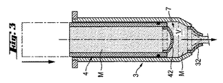
下側の弁通路5はそれぞれ1つの通路壁31によって画定される。この通路壁31は円筒形に形成されていると有利である。下側の弁通路5の下端部には、下側の弁32が設けられており、下側の弁通路5の上端部には、上側の弁42が設けられている。通路壁31と下側の弁32と上側の弁42とにより、1つの調量チャンバ7が規定される。この調量チャンバ7の容積Vは可変であり、下側の弁通路5の可変の区分によって形成されている。
Each
上側の弁ブロック4は同じく、相並んで配置された、互いに平行な多数の上側の弁通路6を有している。上側の弁通路6の横断面は下側の弁通路5の横断面に相当しており、すなわち同じく円形に形成されていると有利である。上側の弁通路6はそれぞれ1つの通路壁41によって画定される。この通路壁41は円筒形に形成されていると有利である。上側の弁通路6の下端部には、上側の弁42が設けられており、上端部では、各上側の弁通路6が1つのマス容器2(図8参照)に接続されている。
The
通路壁31と下側の弁32と上側の弁42とは、容積Vを有する調量チャンバ7を規定している。下側の弁通路5の内側横断面は、上側の弁通路6の外側横断面に相当している。各上側の弁通路6は下側の弁通路5の内部で両弁通路5,6の共通の軸線Xに沿って摺動可能である。通路壁31に対する通路壁41のこのような相対運動により、主として通路壁31と下側の弁32と上側の弁42とによって規定された、調量チャンバ7の容積Vを変えることができる。通路壁41の外面に設けられた環状溝内にシールリング43として支承されている環状のシール部材43により、調量チャンバ7のシールが行われる。このシール部材43により、流し込み可能なマスが通路壁31と通路壁41との間に広がって、コントロールされずに調量チャンバ7から流出する危険が阻止される。環状のシール部材は、通路壁と一体の環状隆起部(図示しない)として形成されていてもよい。選択的に、軸方向で間隔を置いて配置された複数のシールリング43または環状隆起部(図示しない)が通路壁41に設けられていてもよい。
The
下側の弁32は弾性的な材料から形成されている。下側の弁32において、調量チャンバ7と周辺(環境大気)との間の十分に小さな圧力差が存在していると、すなわち所定の最小弁圧力差が上回れないと、弁の弾性的な材料はほぼ未変形のままとなり、下側の弁32は閉じられたままとなる。前記最小弁圧力差が上回れた場合にしか、下側の弁32は開かない。
The
同じことは、上側の弁42にも云える。上側の弁42は同じく弾性的な材料から形成されている。上側の弁42において、弁通路6と調量チャンバ7との間の十分に小さな圧力差が存在していると、すなわち所定の最小弁圧力差が上回れないと、弁の弾性的な材料はほぼ未変形のままとなり、上側の弁42は閉じられたままとなる。前記最小弁圧力差が上回れた場合にしか、上側の弁42は開かない。
The same is true for the
次に、図1、図2、図3、図4、図5および図6につき、本発明による圧力発生手段の構成要素である調量ユニット3,4の機能形式について説明する。 Next, with reference to FIG. 1, FIG. 2, FIG. 3, FIG. 4, FIG. 5 and FIG.
図1には、調量ユニット3,4の流し込みサイクルの第1の段階が示されている。上側の弁ブロック4もしくは各上側の弁通路6は下側の弁ブロック3もしくは各下側の弁通路5から、必要とされる所要調量容量に相当する分だけ軸線Xに沿って引き出されている。上側の弁ブロック4は吸込み行程の終了時に位置していて、下側の弁ブロック3に関して静止している。調量チャンバ7の容積Vはその最大値をとっている。各上側の弁通路6と各下側の弁通路5とは、流し込み可能なマスMで満たされており、このマスMは、実際に吸込みの後に直ちに静止する程度に十分な粘稠性を有している。このことは同時に吐出行程の開始でもある。下側の弁32と上側の弁42とは閉じられている。マスMは静止している。
FIG. 1 shows the first stage of the pouring cycle of the
図2には、流し込みサイクルの第2の段階が示されている。弁ブロック4もしくは各上側の弁通路6は下側の弁ブロック3もしくは各下側の弁通路5内へ軸線Xに沿って押し込まれる。上側の弁42は閉じられており、下側の弁32は開いている。調量チャンバ7内のマスMは調量チャンバ7の減少する容積Vから下側の弁32を通じて吐出される。上側の弁ブロック4は吐出行程途中の位置に位置していて、下側の弁ブロック3に対して運動する。各上側の弁通路6と、各下側の弁通路5とは、吐出行程中に運動するマスMで満たされている。
FIG. 2 shows the second stage of the pouring cycle. The
図3には、流し込みサイクルの第3の段階が示されている。上側の弁ブロック4もしくは各上側の弁通路6は下側の弁ブロック3もしくは各下側の弁通路5内へ、ほぼ必要とされる調量容量に相当する分だけ軸線Xに沿って押し込まれている。上側の弁42は閉じられていて、下側の弁32は相変わらず開いている。調量チャンバ7内のマスMは引き続き下側の弁32を通じて吐出される。上側の弁ブロック4は吐出行程の終了直前の位置に位置していて、まだ下側の弁ブロック3に対して運動する。調量チャンバ7の容積Vはほぼその最小値にまで達している。各上側の弁通路6と各下側の弁通路5とはマスMで満たされている。
FIG. 3 shows the third stage of the pouring cycle. The
図4には、流し込みサイクルの第4の段階が示されている。上側の弁ブロック4もしくは各上側の弁通路6は下側の弁ブロック3もしくは各下側の弁通路5から軸線Xに沿って引き出される。上側の弁42は開いていて、下側の弁32は閉じられている。マスMは上側の弁42を通じて、調量チャンバ7の増大する容積V内へ吸い込まれる。上側の弁ブロック4は吸込み行程途中の位置に位置していて、下側の弁ブロック3に対して運動する。調量チャンバ7の容積Vは増大する。各上側の弁通路6と各下側の弁通路5とは、吸込み行程の間に運動するマスMで満たされている。
FIG. 4 shows the fourth stage of the pouring cycle. The
図5には、流し込みサイクルの第5の段階が示されている。上側の弁ブロック4もしくは各上側の弁通路6は下側の弁ブロック3もしくは各下側の弁通路5から、ほぼ必要とされる調量容量に相当する分だけ軸線Xに沿って引き出されている。上側の弁42は相変わらず開いていて、下側の弁32は相変わらず閉じられている。マスMは引き続き上側の弁42を通じて、調量チャンバ7の増大する容積V内へ吸い込まれる。上側の弁ブロック4は吸込み行程の終了直前の位置に位置していて、まだ下側の弁ブロック3に対して運動している。調量チャンバ7の容積Vはほぼその最大値にまで達している。各上側の弁通路6と、各下側の弁通路5とはマスMで満たされている。
FIG. 5 shows the fifth stage of the pouring cycle. The
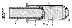
図6には、調量ユニット3,4の流し込みサイクルの第6の段階が示されている。上側の弁ブロック4もしくは各上側の弁通路6は下側の弁ブロック3もしくは各下側の弁通路5から、必要とされる調量容量に相当する分だけ軸線Xに沿って引き出されている。上側の弁ブロック4は吸込み行程の終了時の位置に位置していて、下側の弁ブロック3に対して静止している。調量チャンバ7の容積Vは再びその最大値をとる。各上側の弁通路6と各下側の弁通路5とはマスMで満たされている。このことは同時に吐出行程の開始でもある(図1参照)。下側の弁32と上側の弁42とは閉じられている。マスMは静止している。
FIG. 6 shows the sixth stage of the pouring cycle of the
次に、図7A、図7B、図7Cおよび図7Dにつき、本発明による圧力発生手段の構成要素である調量ユニット3,4の運転中における圧力特性について説明する。
Next, with reference to FIGS. 7A, 7B, 7C, and 7D, pressure characteristics during operation of the
図7Aには、吸込み行程の終了時もしくは吐出行程の開始時における圧力特性が示されている。上側の弁ブロック4は下側の弁ブロック3に対して静止している。マスMは同じく静止している。下側の弁通路5により形成された調量チャンバ7内の圧力P1は、上側の弁通路6内の圧力P2と等しい大きさに形成されている(P1=P2)。ハイドロスタティック的(流体静力学的)な圧力に基づき、圧力P1およびP2の絶対値が、大気圧P0よりも少しだけ高く形成されることが起こり得る。しかし、この圧力差P1−P0=P2−P0は、最小弁圧力差(開放圧)よりも小さく形成されている。
FIG. 7A shows the pressure characteristics at the end of the suction stroke or the start of the discharge stroke. The
図7Bには、吐出行程中の圧力特性が示されている。上側の弁ブロック4は下側の弁ブロック3に対して下方へ向かって運動する。下側の弁通路5により形成された調量チャンバ7内の圧力P1は、上側の弁通路6内の圧力P2よりも大きく形成されている(P1>P2)。上側の弁42は閉じられている。さらに、調量チャンバ7内の圧力P1は大気圧P0よりも大きく形成されている。下側の弁32は開放されている。
FIG. 7B shows the pressure characteristics during the discharge stroke. The
図7Cには、吸込み行程中の圧力特性が示されている。上側の弁ブロック4は下側の弁ブロック3に対して上方へ向かって運動する。下側の弁通路5により形成された調量チャンバ7内の圧力P1は、上側の弁通路6内の圧力P2よりも小さく形成されている(P1<P2)。上側の弁42は開かれている。さらに、調量チャンバ7内の圧力P1は大気圧P0よりも小さく形成されている。下側の弁32は閉じられている。
FIG. 7C shows the pressure characteristics during the suction stroke. The
図7Dには、吸込み行程の終了時における圧力特性が示されている。上側の弁ブロック4は下側の弁ブロック3に対してまだ運動している。下側の弁通路5により形成された調量チャンバ7内の圧力P1は、相変わらず上側の弁通路6内の圧力P2よりも小さく形成されている(P1<P2)。上側の弁42はまだ開放されている。さらに、調量チャンバ7内の圧力P1は大気圧P0よりも小さく形成されている。下側の弁32はまだ閉じられている。
FIG. 7D shows the pressure characteristics at the end of the suction stroke. The
図8には、鉛直な平面に沿って断面された流し込み機械1の斜視図が示されている。この場合、図1〜図7につき説明した調量ユニット3,4はこの流し込み機械の一部を形成している。流し込み機械1は、上方から下方へ向かって配置されて主として3つの構成要素、つまりマス容器2と、複数の上側の弁42を備えた上側の弁ブロック4と、複数の下側の弁32を備えた下側の弁ブロック3とを有している。
FIG. 8 shows a perspective view of the pouring
上側の弁ブロック4はこの場合、プレート状に形成されていて、その上側ではマス容器2に、その下側では多数の円筒状の上側の弁通路6に、それぞれ結合されている。これらの上側の弁通路6は、それぞれ上側の弁ブロック4の平坦な下面に対して垂直に延びていて、それぞれ円筒状の通路壁41によって形成されている。上側の弁通路6の下端部は、それぞれ上側の弁42を有している。マス容器2の底部は多数の孔21を有しており、各孔21はそれぞれ1つの上側の弁通路6に開口している。
In this case, the
下側の弁ブロック3はこの場合、下側のプレート3aと上側のプレート3bとにより形成されている。上下のプレート3a,3bは上側の弁ブロック4とマス容器2の底部とに対して平行に向けられている。両プレート3a,3bは多数の孔を有しており、これらの孔のところで両プレート3a,3bは多数の円筒状の下側の弁通路5を介して結合されている。これらの下側の弁通路5は両プレート3a,3bに設けられた各孔の位置から下側のプレート3aと上側のプレート3bとの間にウェブ状に延びていて、それぞれ1つの円筒状の通路壁31によって形成されている。したがって、下側の弁ブロック3は、下側のプレート3aと上側のプレート3bと多数のウェブ状の下側の弁通路5とにより形成された1つの剛性的なユニットから成っている。各下側の弁通路5の下端部はそれぞれ1つの下側の弁32を有している。
In this case, the
下側の弁ブロック3と上側の弁ブロック4とは、互いにスライド式に支承されている。スライド式の支承部はこの場合、上側の弁通路6の多数の円筒状の通路壁41と、下側の弁通路5の多数の円筒状の通路壁31とにより形成され、この場合、上側の弁通路6の各弁通路壁41の外壁は、下側の弁通路5の各弁通路壁31の内壁に接触しており、互いに同心的な円筒状の両通路壁31,41は各円筒体軸線Xに沿って互いに相対的にスライドし得る。下側の弁ブロック3と上側の弁ブロック4との間でのこのような線状の相対運動により、主として弁通路壁31と下側の弁32と上側の弁42とによって規定された調量チャンバ7の容積Vは変化させられる(図1、図2、図3、図4、図5および図6のサイクル参照)。下側の弁通路5内の圧力特性もしくは下側の弁通路5により決定された調量チャンバ7内部の圧力特性ならびに上側の弁通路6内の圧力特性については、図7A、図7B、図7Cおよび図7Dにつき説明した通りである。
The
流し込み機械1の主要機能のためには、1回の流し込みサイクルの間に下側の弁ブロック3が運動させられかつ上側の弁ブロック4が静止されるのか、あるいは逆に上側の弁ブロック4が運動させられかつ下側の弁ブロック3が静止されるのか、または両弁ブロック3,4が同時にまたは順次に互いに相対的に運動させられるのか、は重要ではない。
For the main function of the pouring
各調量チャンバ7内には、1つの振動エレメント11が設けられている。この振動エレメント11を介して、流し込みたいマスに振動を加えることができる。振動エレメント11はロッドの形を有しており、このロッドは横方向で各調量チャンバ7もしくは各下側の弁通路5を貫いて延びていて、弁通路壁31に支承されている。
One
図9には、本発明による弁50の斜視図が示されている。この弁50は、弾性的な材料、特にエラストマ材料から成る面状のベースボディ51を有している。このベースボディ51は、弁軸線もしくは弁通過方向に沿って見て円形の輪郭を備えている。ベースボディ51は弁通過方向で凸面状に湾曲させられていて、弁50の面中心点を通って延びるスリット52によって貫通されている。これにより、スリット52の両側では、それぞれ1つのほぼ半月形の弁フラップ53が規定されている。
FIG. 9 shows a perspective view of a
図9に斜視図で示した弁50は、図1〜図6に断面図で示した弁32,42に相当している。
The
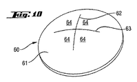
図10には、本発明による別の弁60の斜視図が示されている。弁60は、弾性的な材料、特にエラストマ材料から成る面状のベースボディ61を有している。このベースボディ61は、弁軸線もしくは弁通過方向に沿って見て円形の輪郭を備えている。ベースボディ61は弁通過方向で凸面状に湾曲させられていて、弁60の面中心点を通って延びる第1のスリット62と、この第1のスリット62に面中心点で交差する第2のスリット63とによって貫通されている。互いに交差し合う第1第2の両スリット62,63により、合計4つの弁フラップ64が規定されており、これら4つの弁フラップ64はほぼ直角三角形の形状を有している。
FIG. 10 shows a perspective view of another
図10に斜視図で示した弁60も、図1〜図6に断面図で示した弁32,42に相当している。
The
図11には、本発明によるさらに別の弁70の斜視図が示されている。弁70は、弾性的な材料、特にエラストマ材料から成る面状のベースボディ71を有している。このベースボディ71は、弁軸線もしくは弁通過方向に沿って見て円形の輪郭を備えている。ベースボディ71は弁通過方向で凸面状に湾曲させられていて、弁70の面中心点を通って延びかつ弁70の面中心点で互いに交差し合う4つのスリット72,73,74,75によって貫通されている。互いに交差し合う4つのスリット72,73,74,75により、合計8つの弁フラップ76が規定されており、これら8つの弁フラップ76は、それぞれほぼ鋭角の三角形の形状を有している。
FIG. 11 shows a perspective view of yet another
面状のベースボディ51,61,71の湾曲部しか有しない弁50,60または70の「真っ直ぐな」スリット(図9、図10、図11参照)の代わりに、弁50,60,70のスリットは面状のベースボディ51,61,71内部に付加的な湾曲部をも有していてよい。ベースボディ51,61,71における面中心点(弁軸線と面状のベースボディとの交点)に対して点対称的に配置されたS字形のスリット(図示しない)が有利である。
Instead of the “straight” slit (see FIGS. 9, 10, and 11) of the
図12には、本発明による弁80の斜視図が示されている。弁80は、弾性的な材料、特にエラストマ材料から成るベースボディ81を有している。このベースボディ81は、弁軸線もしくは弁通過方向に沿って見て円形の輪郭を備えている。ベースボディ81からは、弁通過方向で凹面状に湾曲させられた2つの弁フラップ83が突出している。両弁フラップ83の端部は横方向に延びるスリット82に沿って互いに接触していて、したがって1つのスリット付きの稜部84を形成している。
FIG. 12 shows a perspective view of a
スリット82の縁側の端部82aには、ほぼ円形の横断面を有する孔が設けられている。この孔はノッチ状のスリット端部82aに沿って弁80のダイヤフラム状の材料を貫いて延びており、したがってスリット端部82aからノッチ状の特性を奪うので、弁80のダイヤフラム材料内でノッチ応力により生ぜしめられる亀裂成長は阻止される。
The
図13には、本発明による弁90の斜視図が示されている。弁90は、弾性的な材料、特にエラストマ材料から成るベースボディ91を有している。このベースボディ91は、弁軸線もしくは弁通過方向に沿って見て円形の輪郭を備えている。ベースボディ91からは、弁通過方向で凹面状に湾曲させられた4つの弁フラップ94が突出している。これら4つの弁フラップ94の端部は、横方向に延びかつ互いに直角に交差する2つのスリット92,93に沿って互いに接触していて、したがって2つのスリット付きの稜部95,96を形成しており、両稜部95,96は同じく互いに直角に交差している。
FIG. 13 shows a perspective view of a
スリット92,93の縁側の端部92a,93aには、材料溜まりが設けられており、これにより縁側のスリット端部92a,93aを起点とした亀裂形成が阻止される。材料溜まりの代わりに、またはこのような材料溜まりとの組合せの形で、縁側のスリット端部92a,93aに、ほぼ円形の横断面を有する孔が設けられていてよい。これらの孔はノッチ状のスリット端部82はノッチ状のスリット端部92a,93aに沿って弁90のダイヤフラム状の材料を貫いて延びていて、したがってスリット端部92a,93aからそのノッチ状の特性を奪うので、弁90のダイヤフラム材料内にノッチ応力によって生ぜしめられる亀裂成長は阻止される。
The
図14Aおよび図14Bには、本発明による弁100の斜視図が示されている。この場合、図14Aは、弁100を、弁通過方向とはほぼ逆向きの方向で見た図であり、図14Bは、弁100を、弁通過方向とほぼ同じ向きの方向で見た図である。弁100は、弾性的な材料、特にエラストマ材料から成るベースボディ101を有している。このベースボディ101は、弁軸線もしくは弁通過方向に沿って見て円形の輪郭を備えている。ベースボディ101からは、弁通過方向で凹面状に湾曲させられた3つの弁フラップ105が突出している。これら3つの弁フラップ105の端部は、放射状に配置された3つのスリット102,103,104に沿って互いに接触している。これら3つのスリット102,103,104は弁中心部で合流していて、したがってスリット付きの3つの稜部106,107,108を形成している。これらの稜部106,107,108は同じく放射状に配置されていて、弁中心部で合流している。弁中心部と弁縁部との間の各稜部106,107,108の上縁は凹面状に延びている。弁中心部では、稜部106,107,108の合流した上縁が、弁底部(弁ベースボディ101の下縁により形成される仮想平面)から最も大きく上方へ突出している。
14A and 14B show perspective views of a
図15Aおよび図15Bには、本発明による弁110の斜視図が示されている。この場合、図15Aは、弁110を、弁通過方向とはほぼ逆向きの方向で見た図であり、図15Bは、弁110を、弁通過方向とほぼ同じ向きの方向で見た図である。弁110は、弾性的な材料、特にエラストマ材料から成るベースボディ111を有している。このベースボディ111は、弁軸線もしくは弁通過方向に沿って見て円形の輪郭を備えている。ベースボディ111からは、弁通過方向で凹面状に湾曲させられた3つの弁フラップ115が突出している。これら3つの弁フラップ115の端部は、放射状に配置された3つのスリット112,113,114に沿って互いに接触している。これら3つのスリット112,113,114は弁中心部で、その中心部の端部112b,113b,114bのところで合流していて、したがって3つのスリット付きの稜部116,117,118を形成している。これら3つのスリット付きの稜部116,117,118はやはり放射状に配置されていて、弁中心部で合流している。弁中心部と弁縁部との間の各稜部116,117,118の上縁は凹面状に延びている。弁中心部では、稜部116,117,118の合流した上縁が、弁底部(弁ベースボディ111の下縁により形成される仮想平面)から最も大きく上方へ突出している。
15A and 15B show perspective views of a
スリット112,113,114の縁側の端部112a,113a,114aには、材料溜まりが設けられており、これにより縁側のスリット端部112a,113a,114aを起点とした亀裂形成が阻止される。材料溜まりの代わりに、またはこのような材料溜まりとの組合せの形で、縁側のスリット端部112a,113a,114aには、それぞれ円形の横断面を備えた孔が設けられていてよい。これらの孔はノッチ状のスリット端部112a,113a,114aに沿って弁110のダイヤフラム状の材料を貫いて延びていて、したがってスリット端部112a,113a,114aからそのノッチ状の特性を奪うので、弁110のダイヤフラム材料内にノッチ応力によって生ぜしめられる亀裂成長は阻止される。弁110は心臓弁に倣って形成されている。
The
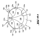
図16Aおよび図16Bには、本発明による弁120の斜視図が示されている。この場合、図16Aは、弁120を、弁通過方向とはほぼ逆向きの方向で見た図であり、図16Bは、弁120を、弁通過方向とほぼ同じ向きの方向で見た図である。弁120は、弾性的な材料、特にエラストマ材料から成るベースボディ121を有している。このベースボディ121は、弁軸線もしくは弁通過方向に沿って見て円形の輪郭を備えている。ベースボディ121からは、弁通過方向で凹面状に湾曲させられた6つの弁フラップ128が突出している。これら6つの弁フラップ128の端部は、放射状に配置された6つのスリット122,123,124,125,126,127に沿って互いに接触している。これら6つのスリット122,123,124,125,126,127は弁中心部で、その中心部側の端部のところで合流していて、したがって6つのスリット付きの稜部129,130,131,132,133,134を形成している。これら6つのスリット付きの稜部129,130,131,132,133,134はやはり放射状に配置されていて、弁中心部で合流している。弁中心部と弁縁部との間の各稜部129,130,131,132,133,134の上縁は凹面状の形状を有している。弁中心部では、稜部129,130,131,132,133,134の合流した上縁が、弁底部(弁ベースボディ121の下縁により形成される仮想平面)から最も大きく上方へ突出している。
16A and 16B show perspective views of a
スリット122,123,124122,123,124,125,126,127の縁側の端部122a,123a,124a,125a,126a,127aには、材料溜まりが設けられており、これにより縁側のスリット端部122a,123a,124a,125a,126a,127aを起点とした亀裂形成が阻止される。材料溜まりの代わりに、またはこのような材料溜まりとの組合せの形で、縁側のスリット端部122a,123a,124a,125a,126a,127aには、それぞれ円形の横断面を備えた孔が設けられていてよい。これらの孔はノッチ状のスリット端部122a,123a,124a,125a,126a,127aに沿って弁120のダイヤフラム状の材料を貫いて延びていて、したがってスリット端部122a,123a,124a,125a,126a,127aからそのノッチ状の特性を奪うので、弁120のダイヤフラム材料内にノッチ応力によって生ぜしめられる亀裂成長は阻止される。弁120の形状は、垂れ下がった梁に載置された、きちんと張られていないテント生地、つまり垂れ下がったテント生地を備えたサーカステントを想起させる。
The
前記各弁90,100,110または120(図13、図14、図15、図16参照)には、剛性的な安定化リングもしくは緊締リング(図示しない)を押し被せることができる。この安定化リングもしくは緊締リングの内径は、無荷重(ロードレス)の弁90,100,110または120の外径よりも小さく形成されている。この安定化リングもしくは緊締リングによって弁90,100,110または120は半径方向に圧縮される。「剛性的」とは、安定化リングもしくは緊締リングのフレキシブル性が弁のフレキシブル性よりも著しく小さいことを意味する。これにより、弁90,100,110または120は、これらの弁の弁フラップが凹面状に形成されていることに基づき、スリットにおけるこれらの弁フラップの押合わせを生ぜしめるプリロード(予荷重)を得る。周方向で弁90,100,110または120を巡るように延びる前記安定化リングは、弁90,100,110または120の軸方向の長さの少なくとも部分区分にわたって延びている。
Each of the
この安定化リングが軸方向に沿って弁90,100,110または120に沿って摺動可能であると特に有利である。凹面状の弁フラップを備えた弁90,100,110または120では、軸方向に沿った安定化リングもしくは緊締リングの摺動により、弁材料内のプリロード(予荷重)の変化が生ぜしめられ、ひいては互いに押し合わされた弁フラップの押圧力の変化、つまりは弁90,100,110または120の閉鎖力の変化が生ぜしめられる。その場合、弁通過方向における安定化リングの軸方向摺動は閉鎖力の増大を生ぜしめる。弁通過方向とは逆向きの方向における安定化リングの軸方向摺動は、閉鎖力の減少を生ぜしめる。
It is particularly advantageous if this stabilization ring is slidable along the
上で図面につき説明した弁50,60,70,80,90,100,110,120は、エラストマ材料から成っていると有利である。安定化または補剛のためには、弁材料の表面または弁材料の内部に複数の補剛リブまたは補剛網状体が設けられていてよい。特に、亀裂成長または亀裂形成を阻止するために織布封入物を使用することができる。局所的な弁補剛は、面状の弁材料の局所的に互いに異なる厚さによっても可能であり、この場合、このような厚さは、有利には弁材料から成る表面リブの形に形成されている。弁は一体に製作され得ると同時に、内在する固有の材料応力(「凍結された」応力状態)をも付与され得る。このような固有の材料応力および/または特殊な弁形状、つまり面状の弁ベースボディの平面に沿った弁の圧縮の克服下に弁の変形および特に弁の折返しが行われるような弁形状により、本発明による弁に作用点を付与することができる。
The
Claims (59)
−流動性のマス(M)を収容するためのマス容器(2)が設けられており;
−少なくとも1つの弁(32,42;50;60;70;80;90;100;110;120)が設けられており、該弁が、マス容器内室に流体接続されており、弁通過方向に沿って所定の圧力差が存在する場合には、前記弁が開かれた状態にあり、弁通過方向に沿って前記圧力差が存在しない場合には、前記弁が閉じられた状態にあり;
−前記弁の弁通過方向に沿って所定の圧力差を発生させるための圧力発生手段(3,4,5,6,32,42)が設けられている;
形式のものにおいて、前記弁が、1つの弁開口と、該弁開口に対応配置された少なくとも1つの弁フラップ(53;64;76;83;94;105;115;128)とを備えた弁ボディ(51;61;71;81;91;101;111;121)を有しており、前記弁フラップが、前記弁ボディに枢着されており、さらに前記弁フラップが、該弁フラップを前記弁開口に押圧しかつ前記弁開口をシールする弾性的なプリロードにさらされていることを特徴とする流し込み機械。 A pouring machine (1) for pouring a flowable mass (M), in particular a liquid mass with suspended solid particles,
A mass container (2) is provided for containing a fluid mass (M);
At least one valve (32, 42; 50; 60; 70; 80; 90; 100; 110; 120) is provided, which is fluidly connected to the chamber of the mass container and in the direction of valve passage The valve is open when a predetermined pressure difference exists along the valve, and the valve is closed when the pressure difference does not exist along the valve passing direction;
-Pressure generating means (3, 4, 5, 6, 32, 42) are provided for generating a predetermined pressure difference along the valve passage direction of the valve;
In the type, the valve comprises one valve opening and at least one valve flap (53; 64; 76; 83; 94; 105; 115; 128) arranged corresponding to the valve opening. A body (51; 61; 71; 81; 91; 101; 111; 121), wherein the valve flap is pivotally attached to the valve body, and the valve flap further connects the valve flap to the valve flap. A casting machine characterized in that it is exposed to an elastic preload that presses against and seals the valve opening.
Applications Claiming Priority (3)
| Application Number | Priority Date | Filing Date | Title |
|---|---|---|---|
| DE102008001323.4 | 2008-04-22 | ||
| DE200810001323 DE102008001323A1 (en) | 2008-04-22 | 2008-04-22 | Casting machine and casting machine valve |
| PCT/EP2009/054647 WO2009130178A2 (en) | 2008-04-22 | 2009-04-20 | Casting machine and casting machine valve |
Publications (2)
| Publication Number | Publication Date |
|---|---|
| JP2011517953A true JP2011517953A (en) | 2011-06-23 |
| JP2011517953A5 JP2011517953A5 (en) | 2012-05-24 |
Family
ID=40907042
Family Applications (1)
| Application Number | Title | Priority Date | Filing Date |
|---|---|---|---|
| JP2011505471A Pending JP2011517953A (en) | 2008-04-22 | 2009-04-20 | Pouring machine and pouring machine valve |
Country Status (7)
| Country | Link |
|---|---|
| US (1) | US8568130B2 (en) |
| EP (1) | EP2282644A2 (en) |
| JP (1) | JP2011517953A (en) |
| CN (1) | CN102014651A (en) |
| BR (1) | BRPI0910474A2 (en) |
| DE (1) | DE102008001323A1 (en) |
| WO (1) | WO2009130178A2 (en) |
Cited By (1)
| Publication number | Priority date | Publication date | Assignee | Title |
|---|---|---|---|---|
| JP2018102301A (en) * | 2012-03-12 | 2018-07-05 | ヤマト農磁株式会社 | Device for distributing and discharging liquid drug, and rice plating simultaneous liquid drug spraying method |
Families Citing this family (9)
| Publication number | Priority date | Publication date | Assignee | Title |
|---|---|---|---|---|
| DE102008043604A1 (en) * | 2008-11-10 | 2010-05-12 | Bühler AG | Casting machine and casting machine valve |
| DE102009000039A1 (en) * | 2009-02-05 | 2010-08-12 | Bühler AG | casting machine |
| DE102010028810B4 (en) * | 2010-05-10 | 2013-08-01 | Saf-Holland Gmbh | Ventilated air bellows for an air spring, air spring containing a ventilated air bellows and air spring system containing ventilated air bellows |
| DK2478773T3 (en) * | 2011-01-25 | 2013-08-26 | Buehler Ag | Molding Machine Valve |
| CN103039674B (en) * | 2013-01-04 | 2014-07-02 | 张彩玲 | Chain-free automatic casting machine for chocolate |
| CN107214044B (en) * | 2013-05-20 | 2019-09-27 | 日本电产增成株式会社 | Liquor device for discharging fixed |
| US10213795B2 (en) | 2015-05-07 | 2019-02-26 | Nordson Corporation | Fluid dispensing apparatus and methods utilizing a resilient nozzle |
| EP3398646B1 (en) | 2017-05-05 | 2019-10-09 | Greatbatch Ltd. | Medical device with hemostatic valve |
| US11092254B1 (en) * | 2020-03-26 | 2021-08-17 | Jose Luis Rueda Calvet | Self-sealing valve for an inflatable body and method for manufacturing same |
Citations (8)
| Publication number | Priority date | Publication date | Assignee | Title |
|---|---|---|---|---|
| JPS5489077A (en) * | 1977-12-27 | 1979-07-14 | Hatsuo Sakurazawa | Quantitatively supplying apparatus of pasty article |
| JPS57177472A (en) * | 1981-04-01 | 1982-11-01 | Tetra Pak Int | Valve gear |
| JPH02233302A (en) * | 1989-01-21 | 1990-09-14 | Elopak Syst Ag | Charging nozzle of vessel |
| JPH0338701U (en) * | 1989-08-24 | 1991-04-15 | ||
| WO1995021531A1 (en) * | 1994-02-08 | 1995-08-17 | Masami Sangyo Co., Ltd. | Dough squeezing nozzle for food machines |
| JPH08334091A (en) * | 1995-06-06 | 1996-12-17 | Naomi:Kk | Filling machine |
| JP2007153354A (en) * | 2005-12-01 | 2007-06-21 | Shikoku Kakoki Co Ltd | Filling nozzle |
| WO2007087731A1 (en) * | 2006-01-31 | 2007-08-09 | Bühler AG | Process and device for casting products intended for human consumption |
Family Cites Families (15)
| Publication number | Priority date | Publication date | Assignee | Title |
|---|---|---|---|---|
| US2524764A (en) * | 1944-04-12 | 1950-10-10 | Adrian P Burke | Valve construction |
| FR1183748A (en) * | 1956-09-19 | 1959-07-13 | Brphidrene Gram As | Discharge spout for viscous masses, method and mechanism for detaching from said spout the rod of viscous mass which emerges therefrom |
| US3211340A (en) * | 1963-04-23 | 1965-10-12 | Waldo H Zander | Dispensing device |
| US3258175A (en) * | 1964-06-09 | 1966-06-28 | Roma Ind Pty Ltd | Dispenser with nipple type control valves |
| US3342318A (en) * | 1965-10-05 | 1967-09-19 | Continental Can Co | Tablet dispenser |
| US3807444A (en) * | 1972-10-10 | 1974-04-30 | Ca Valve Ltd | Check valve |
| DE2438796C2 (en) * | 1974-08-13 | 1983-02-24 | Josef 4422 Ahaus Finnah | Device for filling liquid or pasty filling material in portions into containers |
| US4762308A (en) * | 1987-03-30 | 1988-08-09 | The Firestone Tire & Rubber Company | Damping valve for air spring suspension systems |
| ATE125519T1 (en) * | 1988-12-19 | 1995-08-15 | Drinx Production Ab Svensk Kon | ARRANGEMENT FOR SELECTIVE DISPENSING AND MIXING OF SEVERAL DRINKS. |
| SE508891C2 (en) * | 1993-02-11 | 1998-11-16 | Asept Int Ab | Serving device for portioning two liquid products |
| ATE237766T1 (en) * | 1995-09-01 | 2003-05-15 | Climes Conseil Claude Liardet | VALVE |
| DE29812059U1 (en) * | 1998-07-07 | 1999-01-07 | Lich Goemmer Ingeborg | Device for easy dosing of pasty substances |
| ITMI991312A1 (en) * | 1999-06-11 | 2000-12-11 | Capsol Spa Stampaggio Resine T | AUTOMATIC CLOSURE CAP FOR DISPENSING LIQUIDS FROM DEFORMABLE CONTAINERS |
| BR0110041B1 (en) * | 2000-04-13 | 2009-12-01 | method for coextruding a stream, and extruder. | |
| DE102007024028A1 (en) * | 2007-05-22 | 2008-11-27 | Bühler AG | Device for pouring consumed products |
-
2008
- 2008-04-22 DE DE200810001323 patent/DE102008001323A1/en not_active Withdrawn
-
2009
- 2009-04-20 US US12/988,559 patent/US8568130B2/en not_active Expired - Fee Related
- 2009-04-20 JP JP2011505471A patent/JP2011517953A/en active Pending
- 2009-04-20 BR BRPI0910474A patent/BRPI0910474A2/en not_active IP Right Cessation
- 2009-04-20 EP EP09735801A patent/EP2282644A2/en not_active Withdrawn
- 2009-04-20 CN CN2009801142543A patent/CN102014651A/en active Pending
- 2009-04-20 WO PCT/EP2009/054647 patent/WO2009130178A2/en active Application Filing
Patent Citations (8)
| Publication number | Priority date | Publication date | Assignee | Title |
|---|---|---|---|---|
| JPS5489077A (en) * | 1977-12-27 | 1979-07-14 | Hatsuo Sakurazawa | Quantitatively supplying apparatus of pasty article |
| JPS57177472A (en) * | 1981-04-01 | 1982-11-01 | Tetra Pak Int | Valve gear |
| JPH02233302A (en) * | 1989-01-21 | 1990-09-14 | Elopak Syst Ag | Charging nozzle of vessel |
| JPH0338701U (en) * | 1989-08-24 | 1991-04-15 | ||
| WO1995021531A1 (en) * | 1994-02-08 | 1995-08-17 | Masami Sangyo Co., Ltd. | Dough squeezing nozzle for food machines |
| JPH08334091A (en) * | 1995-06-06 | 1996-12-17 | Naomi:Kk | Filling machine |
| JP2007153354A (en) * | 2005-12-01 | 2007-06-21 | Shikoku Kakoki Co Ltd | Filling nozzle |
| WO2007087731A1 (en) * | 2006-01-31 | 2007-08-09 | Bühler AG | Process and device for casting products intended for human consumption |
Cited By (1)
| Publication number | Priority date | Publication date | Assignee | Title |
|---|---|---|---|---|
| JP2018102301A (en) * | 2012-03-12 | 2018-07-05 | ヤマト農磁株式会社 | Device for distributing and discharging liquid drug, and rice plating simultaneous liquid drug spraying method |
Also Published As
| Publication number | Publication date |
|---|---|
| US20110036432A1 (en) | 2011-02-17 |
| BRPI0910474A2 (en) | 2019-09-24 |
| DE102008001323A1 (en) | 2009-10-29 |
| US8568130B2 (en) | 2013-10-29 |
| WO2009130178A3 (en) | 2010-04-15 |
| WO2009130178A2 (en) | 2009-10-29 |
| CN102014651A (en) | 2011-04-13 |
| EP2282644A2 (en) | 2011-02-16 |
Similar Documents
| Publication | Publication Date | Title |
|---|---|---|
| JP2011517953A (en) | Pouring machine and pouring machine valve | |
| JP4940403B2 (en) | Spray diaphragm pump for spray with the feature of automatically releasing air and preventing pressure abnormality | |
| JP3083666B2 (en) | Pump with valve controllable by transport medium | |
| RU2430831C2 (en) | Filling machine to produce food product from fluid product (versions) and method of producing food product from fluid product | |
| JP7446702B2 (en) | Diaphragm pump | |
| US6679688B2 (en) | Reed valve restriction plate with anti-sticking means | |
| KR101225346B1 (en) | Blade for a single-blade vacuum pump and single-blade vacuum pump | |
| JP2011517953A5 (en) | ||
| KR20160133432A (en) | Applicator head for a dispenser, dispenser comprising an applicator head, and method for producing an applicator head | |
| CN205388167U (en) | A valve that is used for bolt lock of valve and has this kind of bolt lock | |
| KR20110094039A (en) | Casting machine valve, dosing chamber, and casting machine | |
| MX2013008577A (en) | Casting machine valve. | |
| US11274666B2 (en) | Micro-fluid pump | |
| CN112392701B (en) | Micro fluid pump and pressure fluid application device comprising same | |
| JP3373491B2 (en) | Valve unit and container | |
| CN109715976A (en) | Fluid-filled vibration damping device | |
| JP6393551B2 (en) | Diaphragm pump | |
| JPH11257249A (en) | Tube pump | |
| JP3763087B2 (en) | Diaphragm pump | |
| JPH10281070A (en) | Diaphragm pump operating by uniformly distributed load | |
| US11009020B2 (en) | Vacuum pumps and methods of manufacturing the same | |
| EP4269797A1 (en) | Diaphragm pump | |
| CN214036057U (en) | Micro fluid pump and pressure fluid application device comprising same | |
| JP3870847B2 (en) | pump | |
| CN214036059U (en) | Micro fluid pump and pressure fluid application device comprising same |
Legal Events
| Date | Code | Title | Description |
|---|---|---|---|
| A521 | Written amendment |
Free format text: JAPANESE INTERMEDIATE CODE: A523 Effective date: 20120327 |
|
| A621 | Written request for application examination |
Free format text: JAPANESE INTERMEDIATE CODE: A621 Effective date: 20120327 |
|
| A977 | Report on retrieval |
Free format text: JAPANESE INTERMEDIATE CODE: A971007 Effective date: 20130307 |
|
| A131 | Notification of reasons for refusal |
Free format text: JAPANESE INTERMEDIATE CODE: A131 Effective date: 20130319 |
|
| A521 | Written amendment |
Free format text: JAPANESE INTERMEDIATE CODE: A523 Effective date: 20130613 |
|
| A131 | Notification of reasons for refusal |
Free format text: JAPANESE INTERMEDIATE CODE: A131 Effective date: 20130708 |
|
| A02 | Decision of refusal |
Free format text: JAPANESE INTERMEDIATE CODE: A02 Effective date: 20131202 |