JP2011517930A - Baking oven - Google Patents
Baking oven Download PDFInfo
- Publication number
- JP2011517930A JP2011517930A JP2010545415A JP2010545415A JP2011517930A JP 2011517930 A JP2011517930 A JP 2011517930A JP 2010545415 A JP2010545415 A JP 2010545415A JP 2010545415 A JP2010545415 A JP 2010545415A JP 2011517930 A JP2011517930 A JP 2011517930A
- Authority
- JP
- Japan
- Prior art keywords
- baking
- inductor
- plate
- susceptor
- plates
- Prior art date
- Legal status (The legal status is an assumption and is not a legal conclusion. Google has not performed a legal analysis and makes no representation as to the accuracy of the status listed.)
- Pending
Links
Images


Classifications
-
- H—ELECTRICITY
- H05—ELECTRIC TECHNIQUES NOT OTHERWISE PROVIDED FOR
- H05B—ELECTRIC HEATING; ELECTRIC LIGHT SOURCES NOT OTHERWISE PROVIDED FOR; CIRCUIT ARRANGEMENTS FOR ELECTRIC LIGHT SOURCES, IN GENERAL
- H05B6/00—Heating by electric, magnetic or electromagnetic fields
- H05B6/02—Induction heating
- H05B6/10—Induction heating apparatus, other than furnaces, for specific applications
- H05B6/105—Induction heating apparatus, other than furnaces, for specific applications using a susceptor
- H05B6/107—Induction heating apparatus, other than furnaces, for specific applications using a susceptor for continuous movement of material
-
- F—MECHANICAL ENGINEERING; LIGHTING; HEATING; WEAPONS; BLASTING
- F24—HEATING; RANGES; VENTILATING
- F24C—DOMESTIC STOVES OR RANGES ; DETAILS OF DOMESTIC STOVES OR RANGES, OF GENERAL APPLICATION
- F24C15/00—Details
- F24C15/26—Handles for carrying
-
- A—HUMAN NECESSITIES
- A21—BAKING; EDIBLE DOUGHS
- A21B—BAKERS' OVENS; MACHINES OR EQUIPMENT FOR BAKING
- A21B1/00—Bakers' ovens
- A21B1/42—Bakers' ovens characterised by the baking surfaces moving during the baking
- A21B1/48—Bakers' ovens characterised by the baking surfaces moving during the baking with surfaces in the form of an endless band
-
- A—HUMAN NECESSITIES
- A21—BAKING; EDIBLE DOUGHS
- A21B—BAKERS' OVENS; MACHINES OR EQUIPMENT FOR BAKING
- A21B5/00—Baking apparatus for special goods; Other baking apparatus
- A21B5/02—Apparatus for baking hollow articles, waffles, pastry, biscuits, or the like
- A21B5/023—Hinged moulds for baking waffles
-
- F—MECHANICAL ENGINEERING; LIGHTING; HEATING; WEAPONS; BLASTING
- F24—HEATING; RANGES; VENTILATING
- F24C—DOMESTIC STOVES OR RANGES ; DETAILS OF DOMESTIC STOVES OR RANGES, OF GENERAL APPLICATION
- F24C15/00—Details
- F24C15/10—Tops, e.g. hot plates; Rings
-
- F—MECHANICAL ENGINEERING; LIGHTING; HEATING; WEAPONS; BLASTING
- F24—HEATING; RANGES; VENTILATING
- F24C—DOMESTIC STOVES OR RANGES ; DETAILS OF DOMESTIC STOVES OR RANGES, OF GENERAL APPLICATION
- F24C15/00—Details
- F24C15/18—Arrangement of compartments additional to cooking compartments, e.g. for warming or for storing utensils or fuel containers; Arrangement of additional heating or cooking apparatus, e.g. grills
-
- F—MECHANICAL ENGINEERING; LIGHTING; HEATING; WEAPONS; BLASTING
- F24—HEATING; RANGES; VENTILATING
- F24C—DOMESTIC STOVES OR RANGES ; DETAILS OF DOMESTIC STOVES OR RANGES, OF GENERAL APPLICATION
- F24C15/00—Details
- F24C15/30—Arrangements for mounting stoves or ranges in particular locations
Abstract
焼いた成形食品を製造するためのベーキングオーブンである。このベーキングオーブン(219)は、投入ステーション(225)と、ベーキング室(224)と、排出ステーション(226)と、更に、ベーキング室(224)を通る巡回軌道に沿って配置されたベーキングプレート(220)と、ベーキングプレート(220)用の運搬機器(221)とを有する。ベーキングプレート(220)は、非接触式に誘導加熱可能なサセプタプレートとして構成されている。ベーキング室(224)には、誘導加熱部(227)が配備されている。この誘導加熱部は、ベーキングプレート(220)の巡回軌道に対して平行に配置された、巡回軌道に沿って複数のサセプタプレートに渡って拡がる少なくとも一つの長く延びる誘導子(228)を備えている。長く延びる誘導子(228)は、大きな面積の幅の広い磁界を発生させ、その磁界が、サセプタプレートとして構成された複数のベーキングプレート(220)を同時に非接触式に誘導加熱する。 A baking oven for producing baked molded food. The baking oven (219) comprises a baking plate (220) arranged along a circular path passing through a loading station (225), a baking chamber (224), a discharging station (226), and a baking chamber (224). ) And a transport device (221) for the baking plate (220). The baking plate (220) is configured as a susceptor plate capable of induction heating in a non-contact manner. An induction heating unit (227) is disposed in the baking room (224). The induction heating section includes at least one elongated inductor (228) extending parallel to the circular orbit of the baking plate (220) and extending across the plurality of susceptor plates along the circular orbit. . The long extending inductor (228) generates a wide magnetic field having a large area, and the magnetic field induction-heats a plurality of baking plates (220) configured as susceptor plates simultaneously in a non-contact manner.
Description
本発明は、投入ステーション、ベーキング室、排出ステーション、ベーキング室を通る巡回軌道に沿って配置されたベーキングプレート及びベーキングプレート用の運搬機器を備えたベーキングオーブンに関する。 The present invention relates to a baking oven having a loading station, a baking chamber, a discharging station, a baking plate arranged along a circular path passing through the baking chamber, and a conveying device for the baking plate.
そのような形式の周知のベーキングオーブンは、非常に多彩な製品を製造するために使用されている。一つの製品グループには、パンケーキやパラチンケなどが含まれる。別の製品グループには、柔らかいワッフル、アメリカ風パンケーキ、カナダ風パンケーキなどが含まれる。更に別の製品グループには、例えば、さくさくして割れやすいワッフルシートや、多くの中空の半体から成るさくさくして割れやすい平らなワッフルなどのさくさくして割れやすいワッフルが含まれる。更に別の製品グループには、平らなシート、カップ、皿などのワッフルベーキング技術に基づき製造されたパッケージ部分が含まれる。更に別の製品グループには、焼き立ての状態で中空体に変形させた後、中空体として固まるまで放置した、焼き立ての状態で可塑的に変形可能な平らなワッフルから製造するさくさくして割れやすいワッフルが含まれる。そのような製品は、アイスクリーム用の丸めたワッフル製コーン、アイスクリーム用の深絞りしたワッフル製カップ、さくさくして割れやすいワッフル製ロールなどである。 Such types of well-known baking ovens are used to produce a very wide variety of products. One product group includes pancakes and Palachinque. Another product group includes soft waffles, American pancakes and Canadian pancakes. Yet another product group includes waffle sheets that are fragile and fragile, such as, for example, waffle sheets that are fragile and fragile and flat waffles that are composed of many hollow halves. Yet another product group includes package parts manufactured based on waffle baking techniques such as flat sheets, cups, dishes and the like. Yet another product group is a crunchy and fragile waffle made from a flat waffle that is plastically deformable in a freshly baked state, after it has been deformed into a hollow body in a freshly baked state and left to solidify as a hollow body Is included. Such products include rolled waffle cones for ice cream, deep-drawn waffle cups for ice cream, and waffle rolls that are crunchy and fragile.
そのような形式の周知のベーキングオーブンは、大抵ガスで加熱する形のベーキングオーブンとして実現されている。ベーキング室には、ベーキングプレートの巡回軌道に沿って、ガス加熱式赤外線放熱器又は熱い燃焼ガスをベーキング室に放出する一方、巡回するベーキングプレートの裏面側を加熱するガス炎バーナーが配置されている。そのようなベーキングオーブンのフレームには、ベーキング室に配置されたガスバーナーの方に分岐して通じる、燃焼用燃料ガスのための長い配管が格納されている。ベーキングオーブンは、大きな空気取入口を備えており、その取入口を通して、ガスバーナー用の燃焼空気として必要な、並びにガスバーナーが発生した熱い燃焼ガスの冷却に必要な大量の空気をベーキングオーブンに吸入している。 Such types of known baking ovens are usually realized as baking ovens which are heated with gas. In the baking chamber, a gas-heated infrared radiator or a gas flame burner that heats the back side of the circulating baking plate is disposed along the circular orbit of the baking plate while discharging hot combustion gas to the baking chamber. . The frame of such a baking oven stores a long pipe for the combustion fuel gas that branches off to a gas burner arranged in the baking chamber. The baking oven has a large air intake through which a large amount of air necessary for the combustion air for the gas burner and for cooling the hot combustion gas generated by the gas burner is drawn into the baking oven. is doing.
ベーキングプレートに組み込まれた、電気抵抗式加熱器として構成された加熱用螺旋体がベーキングプレートを加熱する所謂電気加熱式ベーキングオーブンも周知である。各ベーキングプレートは、ベーキングプレートに配置された加熱用螺旋体と、ベーキングプレートの裏面側から突き出た集電器とを備えている。ベーキングプレートにおいて、加熱用螺旋体は、ベーキングプレートの裏面側に向かって開いた中空空間内に配置されている。ベーキングプレートの内部において、加熱用螺旋体は、集電器と電気を伝える形で接続されている。集電器自体は、ベーキングプレートの裏面側と移動可能な形で固定されており、ベーキングプレートの裏面側から集電器を押し出すためのスプリングを備えている。電気抵抗式加熱器を備えたベーキングプレートは、ベーキングオーブンの運搬機器によって、ベーキング室を通して運搬される。ベーキング室には、ベーキングプレートの巡回軌道に沿って、電源レールが配置されている。ベーキングプレートがベーキング室に入ると、その集電器が、電源レールと係合する。その際、集電器は、それぞれベーキングプレートの裏面側に対して押され、そのスプリングも一緒に押される。ベーキング室において、集電器は、電源レールに沿ってスライドして行き、電源レールとの接触によって、電源レールから電流を導入して、各ベーキングプレートの加熱用螺旋体に電流を転送している。ベーキングプレートがベーキング室から出ると、集電器は、電源レールから引き上げられて、そのスプリングも緩和される。そして、集電器は、その緩和された初期状態に押し戻される。 A so-called electric heating baking oven in which a heating spiral configured as an electric resistance heater incorporated in a baking plate heats the baking plate is also well known. Each baking plate includes a heating spiral disposed on the baking plate and a current collector protruding from the back side of the baking plate. In the baking plate, the heating spiral is arranged in a hollow space opened toward the back surface side of the baking plate. Inside the baking plate, the heating helix is connected to the current collector in a manner to conduct electricity. The current collector itself is fixed in a movable manner to the back surface side of the baking plate, and includes a spring for pushing the current collector from the back surface side of the baking plate. Baking plates with electrical resistance heaters are transported through the baking chamber by baking oven transport equipment. In the baking room, power rails are arranged along the circular orbit of the baking plate. When the baking plate enters the baking chamber, its current collector engages the power rail. At that time, the current collector is pressed against the back side of the baking plate, and the spring is also pressed together. In the baking chamber, the current collector slides along the power rail, introduces current from the power rail by contact with the power rail, and transfers the current to the heating spiral of each baking plate. As the baking plate exits the baking chamber, the current collector is lifted from the power rail and its springs are relaxed. The current collector is then pushed back to its relaxed initial state.
本発明の課題は、冒頭に述べた形式のベーキングオーブンを改善することである。 The object of the present invention is to improve a baking oven of the type mentioned at the outset.
そのために、本発明は、投入ステーション、ベーキング室及び排出ステーションと、更に、ベーキング室を通る巡回軌道に沿って配置されたベーキングプレート及びベーキングプレート用の運搬機器とを備えた新しいベーキングオーブンを提案する。この新しいベーキングオーブンでは、ベーキングプレートが、非接触式に誘導加熱可能なサセプタプレートとして構成されており、ベーキング室には、誘導加熱部を備えたベーキングゾーンが配設されており、そのゾーンには、ベーキングプレートの巡回軌道に対して平行に配置された、巡回軌道に沿って複数のベーキングプレートに渡って拡がる少なくとも一つの長く延びる誘導子が配備されており、その誘導子は、巡回軌道に沿って複数のベーキングプレートに渡って拡がる大きな面積で幅の広い磁界を発生させ、その磁界が、サセプタプレートとして構成された複数のベーキングプレートを同時に非接触式に誘導加熱する。 To that end, the present invention proposes a new baking oven comprising a loading station, a baking chamber and a discharging station, and further a baking plate and a conveying device for the baking plate arranged along a circular path through the baking chamber. . In this new baking oven, the baking plate is configured as a susceptor plate capable of induction heating in a non-contact manner, and the baking chamber is provided with a baking zone having an induction heating unit. At least one elongated inductor arranged in parallel with the circular orbiting of the baking plate and extending across the baking plates along the circular orbit, the inductor being arranged along the circular orbit A wide magnetic field is generated with a large area extending over the plurality of baking plates, and the magnetic fields induction-heat the plurality of baking plates configured as susceptor plates simultaneously in a non-contact manner.
この新しいベーキングオーブンは、ガス加熱式ベーキングオーブンと比べて、ベーキング室でガスバーナーによって熱い燃焼ガスを発生させる必要が無く、その結果それに応じてベーキングオーブンの構造を簡略化できるという利点を有する。本発明によるベーキングオーブンでは、ガスバーナーに通じる燃焼用燃料ガスのための配管も、ガスバーナー用の燃焼空気として必要な、或いはガスバーナーが発生する熱い燃焼ガスの冷却に必要な大量の空気をベーキングオーブン内に吸入するための大きな空気取入口も不要である。 This new baking oven has the advantage over the gas heating baking oven that there is no need to generate hot combustion gases by means of a gas burner in the baking chamber, and consequently the baking oven structure can be simplified accordingly. In the baking oven according to the present invention, the piping for the combustion fuel gas leading to the gas burner is also baked with a large amount of air necessary for the combustion air for the gas burner or for cooling the hot combustion gas generated by the gas burner. There is no need for a large air intake for inhalation into the oven.
この新しいベーキングオーブンは、前述した電気加熱式ベーキングオーブンと比べて、このベーキングプレートでは、ベーキングプレートに組み込む加熱用螺旋体もベーキングプレートから突き出た集電器も不要となり、このベーキング室では、集電器用スライドレールとして構成された電源レールが不要となるため、ベーキングプレートもベーキングオーブンの構造も大幅に簡略化できるという利点を有する。 Compared with the electric heating baking oven described above, this new baking oven eliminates the need for a heating spiral incorporated in the baking plate and a current collector protruding from the baking plate. Since the power supply rail configured as a rail is not required, the structure of the baking plate and baking oven can be greatly simplified.
この新しいベーキングオーブンでは、ベーキングプロセスに必要な処理熱が、それぞれサセプタプレートとして構成されたベーキングプレートを非接触式に誘導加熱することによって発生する。この新しいベーキングオーブンでは、ベーキングプレートの巡回軌道に対して平行に配置された長く延びる誘導子が、順番に配置された複数のサセプタプレートに渡って拡がっている。この誘導子は、幅が広く大きな面積の磁界を発生させ、その磁界が、巡回軌道に沿って複数のサセプタプレートに渡って拡がるとともに、これらのサセプタプレートを非接触式に誘導加熱する。 In this new baking oven, the processing heat required for the baking process is generated by non-contact induction heating of baking plates each configured as a susceptor plate. In this new baking oven, long extending inductors arranged parallel to the baking plate's circular trajectory extend over a plurality of susceptor plates arranged in sequence. The inductor generates a magnetic field having a large width and a large area, and the magnetic field spreads across a plurality of susceptor plates along a circular trajectory and inductively heats these susceptor plates in a non-contact manner.
本発明の別の特徴では、ベーキングプレートは、重ねて配置された二つの水平な運搬軌道を通る巡回軌道に沿って配置され、二つの運搬軌道には、ベーキングゾーンが配設されており、そのゾーンには、ベーキングプレートの巡回軌道に対して平行に配置された長く延びる誘導子が配備されており、その誘導子の磁界によって、サセプタプレートとして構成された複数のベーキングプレートを同時に非接触式に誘導加熱するものと規定することができる。 In another aspect of the present invention, the baking plate is disposed along a circular trajectory passing through two horizontal transport tracks arranged in a stack, and the two transport tracks are provided with a baking zone. The zone is provided with a long extending inductor arranged parallel to the circular orbit of the baking plate, and a plurality of baking plates configured as susceptor plates are simultaneously brought into a non-contact manner by the magnetic field of the inductor. It can be defined as induction heating.
本発明の別の特徴では、ベーキングプレートが、円形の巡回軌道に沿って配置されるとともに、垂直な回転軸の周りを回転可能な回転テーブルと固定されており、その回転テーブルが、回転運動によって、ベーキングプレートをベーキング室を通して運搬し、ベーキング室には、ベーキングゾーンが配設されており、そのゾーンには、少なくとも一つの長く延びる誘導子が配備されており、その誘導子が、円形の巡回軌道に対して平行に配置されるとともに、円形の巡回軌道に沿ってサセプタプレートとして構成された複数のベーキングプレートに渡って拡がるものと規定することができる。 In another aspect of the present invention, the baking plate is disposed along a circular circular path and is fixed to a rotary table that is rotatable about a vertical rotation axis. The baking plate is transported through the baking chamber, the baking chamber being provided with a baking zone, in which at least one elongated inductor is provided, the inductor being arranged in a circular circuit It can be defined as extending parallel to the track and extending over a plurality of baking plates configured as susceptor plates along a circular circuit track.
ベーキングゾーンにおいて、ベーキングプレートの巡回軌道の下に、長く延びる誘導子を配置することができる。 In the baking zone, a long extending inductor can be arranged under the circular orbit of the baking plate.
ベーキングゾーンにおいて、ベーキングプレートの巡回軌道の上に、長く延びる誘導子を配置することができる。 In the baking zone, a long extending inductor can be arranged on the circular orbit of the baking plate.
ベーキングゾーンにおいて、ベーキングプレートの巡回軌道の上と下に、少なくとも一つの長く延びる誘導子を配置することができる。 In the baking zone, at least one elongated inductor can be arranged above and below the circular orbit of the baking plate.
本発明の別の実施形態では、ベーキング室を通る二つの巡回軌道に沿って配置された、それぞれサセプタプレートとして構成された上方と下方のベーキングプレートが配備されており、それらのベーキングプレートは、ベーキングトング内に収容されており、それらのベーキングトングは、ベーキング室を通る巡回軌道に沿って配置されるとともに、ベーキングオーブンの運搬機器によって、閉じた状態でベーキング室を通して運搬される新しいベーキングオーブンを提案する。このベーキングオーブンでは、ベーキング室に、少なくとも一つのベーキングゾーンが配設されており、そのゾーンには、ベーキングトングの巡回軌道の上と下に、それぞれ少なくとも一つの長く延びる誘導子が配置されており、その誘導子の磁界によって、複数のベーキングトングのサセプタプレートを同時に非接触式に誘導加熱する。 In another embodiment of the present invention, there are provided upper and lower baking plates, each configured as a susceptor plate, arranged along two circular trajectories through the baking chamber, the baking plates being baked. Housed in tongs, these baking tongs are arranged along a circular trajectory through the baking chamber, and a new baking oven is proposed that is transported through the baking chamber in a closed state by the baking oven transport equipment To do. In this baking oven, at least one baking zone is disposed in the baking chamber, and at least one long extending inductor is disposed above and below the circular path of the baking tong, respectively. The susceptor plates of a plurality of baking tongs are induction-heated simultaneously in a non-contact manner by the magnetic field of the inductor.
このベーキングオーブンでは、焼き上がった成形食品は、閉じたベーキングトング内において、重ねて配置された、サセプタプレートとして構成された上方と下方のベーキングプレートの間に出来上がる。 In this baking oven, the baked molded food is produced between upper and lower baking plates configured as susceptor plates, which are arranged one on top of another in a closed baking tong.
本発明において、ベーキングトングを備えたベーキングオーブンでは、複数のベーキングトングが、円軌道に沿って並んで配置されるとともに、垂直な回転軸の周りを回転可能な回転テーブルと固定されており、ベーキング室では、少なくとも一つのベーキングゾーンが円軌道に配設されており、そのゾーンでは、円軌道の上と下に、それぞれ少なくとも一つの長く延びるアーチ形状の誘導子が配置されており、その誘導子の磁界によって、複数のベーキングトングのサセプタプレートを同時に非接触式に誘導加熱するものと規定する。 In the present invention, in a baking oven provided with a baking tong, a plurality of baking tongs are arranged side by side along a circular orbit and fixed to a rotary table that can rotate around a vertical rotation axis. In the chamber, at least one baking zone is arranged in a circular orbit, in which at least one elongated arch-shaped inductor is arranged above and below the circular orbit, respectively, and the magnetic field of the inductor Defines that the susceptor plates of a plurality of baking tongs are simultaneously inductively heated in a non-contact manner.
更に、本発明において、ベーキングトングを備えたベーキングオーブンでは、サセプタプレートとして構成された上方と下方のベーキングプレートを有するベーキングトングが、ベーキング室において、重ねて配置された二つの水平な運搬軌道を通る巡回軌道に沿って配置されており、二つの運搬軌道には、ベーキングゾーンが配設されており、そのゾーンでは、運搬軌道の上と下に、それぞれ少なくとも一つの長く延びる誘導子が配置されており、その誘導子の磁界によって、複数のベーキングトングのサセプタプレートを同時に非接触式に誘導加熱するものと規定する。 Furthermore, in the present invention, in a baking oven with a baking tong, the baking tong having an upper and lower baking plate configured as a susceptor plate passes through two horizontal transport tracks arranged in the baking chamber. It is arranged along a circular orbit, and a baking zone is arranged in the two conveying tracks, in which at least one elongated inductor is arranged above and below the conveying track, It is defined that the susceptor plates of a plurality of baking tongs are simultaneously inductively heated in a non-contact manner by the magnetic field of the inductor.
更に、本発明において、ベーキングトングでは、上方のトング部分が、ヒンジによって、下方のトング部分と旋回可能な形で接続されており、二つのトング部分内のサセプタプレートが、それぞれサセプタプレートの側方に繋がる二つの終端部材の間に配置されており、ベーキングトングのヒンジ側に配置された、二つのトング部分の終端部材は、ヒンジによって互いに接続されるとともに、上方のトング部分の自由端に配置された終端部材が、ベーキングトングを開閉するための制御ローラーを支持するものと規定することができる。 Further, in the present invention, in the baking tongue, the upper tongue portion is connected to the lower tongue portion by a hinge so as to be pivotable, and the susceptor plates in the two tongue portions are respectively lateral to the susceptor plate. The end members of the two tongue parts are arranged between the two end members that are connected to each other and arranged on the hinge side of the baking tongue, and are connected to each other by the hinges, and are arranged at the free end of the upper tongue part The terminated end member can be defined as supporting a control roller for opening and closing the baking tongue.
本発明の別の特徴では、ベーキングトングにおいて、二つのトング部分の終端部材に対して、サセプタプレートを電気的に絶縁することができる。そのような構成によって、ベーキングトングの二つのトング部分内の誘導加熱をサセプタプレートとして構成されたベーキングプレートに制限することが可能となる。 In another aspect of the present invention, the susceptor plate can be electrically isolated from the termination members of the two tongue portions in the baking tong. Such a configuration makes it possible to limit the induction heating in the two tongue portions of the baking tong to a baking plate configured as a susceptor plate.
本発明の別の特徴では、ベーキングトングにおいて、ベーキングトングのヒンジと逆側の側端に、ベーキングトングロック機器を配備することができ、そのロック部品は、ベーキングトングのヒンジと逆側の側端上のサセプタプレートと並んで配置された二つのトング部分の各終端部材に取り付けられている。 In another aspect of the present invention, a baking tong lock device may be provided on the side of the baking tongue opposite to the hinge of the baking tongue, and the locking part is located on the side of the baking tongue opposite to the hinge of the baking tongue. Attached to each end member of the two tongs arranged side by side with the upper susceptor plate.
本発明の別の特徴では、ベーキングトングにおいて、二つのトング部分は、平坦なプレートフレームを備えており、そのフレームには、裏面側を露出させた形で、サセプタプレートを配置することができる。 In another aspect of the present invention, in the baking tongue, the two tongue portions are provided with a flat plate frame, and the susceptor plate can be disposed on the frame with the back side exposed.
本発明では、平坦なプレートフレームは、サセプタプレートの両側に配置された側方のフレーム部分を備えることができ、これらのフレーム部分は、サセプタプレートの前縁に沿って配置された前方の横桁と、サセプタプレートの後縁に沿って配置された後方の横桁とによって互いに接続されている。 In the present invention, the flat plate frame can comprise side frame portions disposed on opposite sides of the susceptor plate, the frame portions being forward cross beams disposed along the front edge of the susceptor plate. And a rear cross beam arranged along the rear edge of the susceptor plate.
本発明では、平坦なプレートフレームにおいて、サセプタプレートは、それぞれ旋回可能な形で軸支するか、或いはプレート面の垂直方向に対して限定的にスライド可能な形で配置することができる。そのような構成によって、閉じられたベーキングトング内の二つのサセプタプレートの間に配置された、ベーキングプロセスの開始時に膨張する生地が、ベーキングトングが閉じられているにも関わらず、上方のトング部分に配置されたサセプタプレートを持ち上げることが可能となる。 In the present invention, in a flat plate frame, the susceptor plates can be pivotally supported in a swingable manner, or can be arranged so as to be slidable with respect to the vertical direction of the plate surface. With such a configuration, the dough that expands at the beginning of the baking process, located between the two susceptor plates in the closed baking tongs, has been removed even though the baking tongs are closed. It is possible to lift the susceptor plate arranged on the surface.
本発明では、平坦なプレートフレームの横桁において、プレート面の垂直方向に対して限定的にスライド可能な形でサセプタプレートを配置することができる。 According to the present invention, the susceptor plate can be arranged in a form that can be slid in a limited manner with respect to the vertical direction of the plate surface in the cross beam of the flat plate frame.
上方と下方のトング部分の平坦なプレートフレームでは、二つの横桁を二つの側方のフレーム部分に対して電気的に絶縁することができる。そのような構成によって、誘導加熱を平坦なプレートフレーム内に配置された、サセプタプレートとして構成されたベーキングプレートに制限することが可能となる。 In the flat plate frame of the upper and lower tongue parts, the two cross beams can be electrically isolated from the two side frame parts. Such a configuration makes it possible to limit induction heating to a baking plate configured as a susceptor plate arranged in a flat plate frame.
本発明の別の特徴では、サセプタプレートは、そのプレートに埋め込まれた、ベーキング押型の半体として形成されたインサート部品を備えることができる。この場合、サセプタプレートを鋳鉄又は鋼鉄から構成し、ベーキング押型の半体として形成されたインサート部品をアルミニウムから構成することができる。 In another aspect of the present invention, the susceptor plate can comprise an insert part formed as a baking die half embedded in the plate. In this case, the susceptor plate can be made of cast iron or steel, and the insert part formed as a baking die half can be made of aluminum.
本発明の別の実施形態では、ベーキング室を通る二つの巡回軌道に沿って配置された、それぞれサセプタプレートとして構成されるとともに、二つの別個のチェーンコンベヤーに配置された上方と下方のベーキングプレートを備えた新しいベーキングオーブンを提案する。二つの巡回軌道は、それぞれ投入ステーションからベーキング室を通って排出ステーションにまで延びる、ベーキング区間に沿って配置されたベーキング部分と、排出ステーションから戻って投入ステーションにまで通じるリターン部分とを有する。二つの巡回軌道の中のベーキング部分のベーキング区間に沿って配置されたサセプタプレートは、互いに対向するとともに、それぞれ上方と下方のベーキングプレートから成るベーキング押型を構成する。ベーキング室には、少なくとも一つのベーキングゾーンが配設されており、そのゾーンには、ベーキング区間に沿って配置されたベーキング押型の上と下に、それぞれ少なくとも一つの長く延びる誘導子が配置されており、その誘導子の磁界によって、複数のベーキング押型のサセプタプレートを同時に非接触式に誘導加熱する。 In another embodiment of the invention, the upper and lower baking plates are arranged as two susceptor plates, respectively, arranged along two circular trajectories through the baking chamber, and arranged on two separate chain conveyors. We propose a new baking oven equipped. The two patrol tracks each have a baking portion arranged along the baking section extending from the charging station through the baking chamber to the discharging station, and a return portion returning from the discharging station to the charging station. The susceptor plates arranged along the baking section of the baking portion in the two circular tracks are opposed to each other and constitute baking stamps each composed of upper and lower baking plates. At least one baking zone is disposed in the baking chamber, and at least one long extending inductor is disposed above and below the baking stamp disposed along the baking section, respectively. A plurality of baking stamp susceptor plates are simultaneously induction-heated in a non-contact manner by the magnetic field of the inductor.
このベーキングオーブンでは、焼き上がった成形食品が、ベーキング区間に沿って順番に配置されたベーキング押型の中に出来上がる。 In this baking oven, the baked molded food is completed in baking stamps arranged in order along the baking section.
そのようなベーキングオーブンでは、二つの巡回軌道のベーキング部分は、ベーキング室において、重ねて配置された二つの水平な運搬軌道を通るベーキング区間に沿って配置することができ、それらの運搬軌道には、それぞれベーキングゾーンが配設されており、そのゾーンでは、ベーキング押型の上と下に、それぞれ少なくとも一つの長く延びる誘導子が配置されており、その誘導子の磁界によって、複数のベーキング押型のサセプタプレートを同時に非接触式に誘導加熱する。 In such a baking oven, the baking part of the two traveling tracks can be arranged in a baking room along a baking section through two horizontal conveying tracks arranged one on top of the other, In this zone, at least one long extending inductor is arranged above and below the baking stamp, and a plurality of baking stamp susceptor plates are formed by the magnetic field of the inductor. At the same time, induction heating is performed in a non-contact manner.
本発明の別の特徴では、サセプタプレートとして構成された上方と下方のベーキングプレートは、ベーキング部分が水平な運搬軌道に沿って配置された二つの巡回軌道に沿って配置されるとともに、ベーキング室には、その水平なベーキング区間に沿って延びるベーキングゾーンが配設されており、そのゾーンが、ベーキング押型の上に配置された長く延びる少なくとも一つの上方の誘導子とベーキング押型の下に配置された長く延びる少なくとも一つの下方の誘導子とを有するベーキングオーブンを規定することができる。 In another aspect of the invention, the upper and lower baking plates configured as susceptor plates are arranged along two circular tracks whose baking parts are arranged along a horizontal transport track and in the baking chamber. Is provided with a baking zone extending along its horizontal baking section, the zone being located under the baking stamp and at least one elongated inductor extending above the baking stamp. A baking oven can be defined having at least one lower inductor extending long.
更に、本発明では、そのようなベーキングオーブンにおいて、上方のベーキングプレートは、上方の巡回軌道に沿って配置されるとともに、ベーキング面を下方に向けて、上方のチェーンコンベヤーから自由に揺動する形で吊り下げられており、下方のベーキングプレートは、下方の巡回軌道に沿って配置されるとともに、下方のチェーンコンベヤーによって、ベーキング区間を通して運搬され、上方のベーキングプレートは、上方のチェーンコンベヤーによって、ベーキング区間の始めで下方のベーキングプレート上に降ろされて、ベーキング区間の終わりで下方のベーキングプレートから引き上げられ、下方のチェーンコンベヤーは、それぞれ下方のベーキングプレートと、その上に降ろされる上方のベーキングプレートとから成るベーキング押型をベーキング区間に沿ってベーキングゾーンを通して運搬するものと規定することができる。 Further, according to the present invention, in such a baking oven, the upper baking plate is disposed along the upper circular path, and the baking surface is directed downward, and freely swings from the upper chain conveyor. The lower baking plate is arranged along the lower circular path and is transported through the baking section by the lower chain conveyor, and the upper baking plate is baked by the upper chain conveyor. Lowered on the lower baking plate at the beginning of the section and lifted from the lower baking plate at the end of the baking section, and the lower chain conveyors respectively have a lower baking plate and an upper baking plate lowered onto it. The base consisting of Can be defined to be conveyed through the baking zone along the ring mold-pressing the baking section.
本発明では、下方のベーキングプレートが、投入ステーションからベーキング室を通って排出ステーションにまで通じる、ベーキング区間に沿って配置されたベーキング部分と、排出ステーションから戻って投入ステーションにまで通じるリターン部分とを有する巡回軌道に配置されたベーキングオーブンにおいて、誘導加熱部が、下方のベーキングプレートの巡回軌道のリターン部分に、少なくとも一つの追加の長く延びる誘導子を備えており、その誘導子の磁界によって、複数の下方のベーキングプレートのサセプタプレートを同時に非接触式に誘導加熱するものと規定することができる。 In the present invention, the lower baking plate has a baking portion disposed along the baking section that leads from the charging station through the baking chamber to the discharging station, and a return portion that returns from the discharging station to the charging station. In the baking oven arranged in the circular orbit, the induction heating unit includes at least one additional long extending inductor in the return portion of the circular orbit of the lower baking plate. It is possible to define that the susceptor plate of the lower baking plate is simultaneously inductively heated in a non-contact manner.
本発明では、上方のベーキングプレートが、投入ステーションからベーキング室を通って排出ステーションにまで通じる、ベーキング区間に沿って配置されたベーキング部分と、排出ステーションから戻って投入ステーションにまで通じるリターン部分とを有する巡回軌道に配置されたベーキングオーブンにおいて、誘導加熱部が、上方のベーキングプレートの巡回軌道のリターン部分に、少なくとも一つの追加の長く延びる誘導子を備えており、その誘導子の磁界によって、複数の上方のベーキングプレートのサセプタプレートを同時に非接触式に誘導加熱するものと規定することができる。 In the present invention, the upper baking plate has a baking portion arranged along the baking section that leads from the charging station through the baking chamber to the discharging station, and a return portion that returns from the discharging station to the charging station. In the baking oven arranged in the circular orbit, the induction heating unit is provided with at least one additional long extending inductor in the return portion of the upper orbiting plate's circular orbit. It can be defined that the susceptor plate of the upper baking plate is simultaneously inductively heated in a non-contact manner.
本発明の別の特徴では、サセプタプレートとして構成された上方と下方のベーキングプレートが、二つの別個のチェーンコンベヤーに配置されたベーキングオーブンにおいて、少なくとも下方のベーキングプレートは、その巡回軌道に沿って配置されたチェーンコンベヤーに対して電気的に絶縁することができる。本発明では、上方のベーキングプレートも、その巡回軌道に沿って配置されたチェーンコンベヤーに対して電気的に絶縁することができる。 In another feature of the invention, in a baking oven in which the upper and lower baking plates configured as susceptor plates are arranged in two separate chain conveyors, at least the lower baking plate is arranged along its circular path. Can be electrically isolated from the chain conveyor. In the present invention, the upper baking plate can also be electrically insulated from the chain conveyor arranged along its circular path.
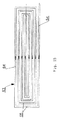
本ベーキングオーブンは、誘導加熱部を備えている。本発明では、そのような誘導加熱部において、各ベーキングゾーンには、ベーキングプレートの巡回軌道に沿って複数のベーキングプレートに渡って拡がる長く延びる誘導子が配置されており、その誘導子は、幅の広い磁界を発生させ、その磁界が、ベーキングプレートの巡回軌道に沿って複数のベーキングプレートに渡って拡がるとともに、サセプタプレートとして構成された複数のベーキングプレートを同時に非接触式に誘導加熱するものと規定することができる。 The baking oven includes an induction heating unit. In the present invention, in such an induction heating section, each baking zone is provided with a long extending inductor that extends over a plurality of baking plates along a circular orbit of the baking plate, and the inductor has a width of A wide magnetic field is generated, and the magnetic field spreads across a plurality of baking plates along the circular orbit of the baking plate, and at the same time, a plurality of baking plates configured as susceptor plates are induction-heated in a non-contact manner simultaneously. Can be prescribed.
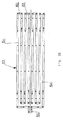
本発明では、長く延びる誘導子は、並んで配置された、ベーキングプレートの巡回軌道に沿って複数のベーキングプレートに渡って拡がるとともに、互いに平行に延びる二つ以上の誘導子ストリップを備えることができる。 In the present invention, the elongated inductor may comprise two or more inductor strips arranged side by side and extending across a plurality of baking plates along a circular orbit of the baking plate and extending parallel to each other. .
本発明の別の特徴では、この長く延びる誘導子は、互いに平行に延びるとともに、それぞれ独自の誘導子ループを形成する幾つかの誘導子ストリップを備えることができる。この構成では、各誘導子ストリップは、独自の電流配線を介して、誘導加熱部の交流発生器と接続される。 In another aspect of the invention, the elongated inductor may comprise several inductor strips that extend parallel to each other and each form a unique inductor loop. In this configuration, each inductor strip is connected to an AC generator of the induction heating unit via a unique current wire.
本発明の別の特徴では、この長く延びる誘導子は、並んで配置された、それぞれ独自の誘導子ループを形成するU字形状の誘導子で構成することができ、これらの誘導子は、それぞれ互いに平行に延びる二つの誘導子ストリップを有する。この構成では、各U字形状の誘導子は、独自の電流配線を介して、誘導加熱部の交流発生器と接続される。 In another aspect of the invention, the elongated inductors can be composed of U-shaped inductors that are arranged side-by-side, each forming its own inductor loop, each of these inductors being It has two inductor strips extending parallel to each other. In this configuration, each U-shaped inductor is connected to an AC generator of the induction heating unit via a unique current wiring.
本発明の別の特徴では、この長く延びる誘導子は、並んで配置された、それぞれ独自の誘導子ループを形成する二つの誘導子で構成することができ、これらの誘導子では、互いに平行に延びる誘導子ストリップの終端が、横方向のストリップによって接続されるとともに、その横方向のストリップと共に、誘導子の長手方向に長く延びる螺旋体を形成する。この構成では、二つの並んで配置された誘導子は、それぞれ独自の電流配線を介して、誘導加熱部の交流発生器と接続される。 In another aspect of the invention, the elongated inductor may be composed of two inductors arranged side by side, each forming its own inductor loop, in which these inductors are parallel to each other. The ends of the extending inductor strip are connected by a transverse strip and together with the transverse strip form a spiral that extends long in the longitudinal direction of the inductor. In this configuration, the two inductors arranged side by side are connected to the AC generator of the induction heating unit via their own current wiring.
本発明の別の特徴では、この長く延びる誘導子は、単一の誘導子ループとして構成することができ、その互いに平行に延びる誘導子ストリップの終端は、横方向のストリップによって接続されるとともに、その横方向のストリップと共に、誘導子の長手方向に長く延びる螺旋体を形成する。この構成では、長く延びる誘導子は、ただ一つの電流配線を介して、誘導加熱部の交流発生器と接続される。 In another aspect of the invention, the elongated inductor may be configured as a single inductor loop, the ends of the inductor strips extending parallel to each other are connected by lateral strips, Together with the transverse strip, it forms a spiral that extends long in the longitudinal direction of the inductor. In this configuration, the long extending inductor is connected to the AC generator of the induction heating unit via only one current wiring.
本発明の別の特徴では、この長く延びる誘導子は、二つの並んで配置された半ループから成る単一の誘導子ループとして構成することができ、その互いに平行に延びる誘導子ストリップの終端は、横方向のストリップによって接続されるとともに、その横方向のストリップと共に、誘導子の長手方向に長く延びる螺旋体を形成する。この構成では、長く延びる誘導子は、ただ一つの電流配線を介して、誘導加熱部の交流発生器と接続される。 In another aspect of the invention, the elongated inductor can be configured as a single inductor loop consisting of two side-by-side half loops, with the ends of the inductor strips extending parallel to each other being , Which are connected by a lateral strip and together with the lateral strip form a spiral that extends long in the longitudinal direction of the inductor. In this configuration, the long extending inductor is connected to the AC generator of the induction heating unit via only one current wiring.
本発明の別の特徴では、誘導子ストリップは、それらを接続する横方向のストリップと共に、一方の半ループでは時計方向に回る螺旋体を形成し、他方の半ループでは反時計方向に回る螺旋体を形成することができる。 In another aspect of the invention, the inductor strips, together with the transverse strips connecting them, form a spiral that turns clockwise in one half loop and a spiral that turns counterclockwise in the other half loop. can do.
本発明の別の特徴では、誘導子ストリップは、それらを接続する横方向のストリップと共に、二つの半ループにおいて同じ方向に回る螺旋体を形成することができる。 In another aspect of the invention, the inductor strips, together with the transverse strips connecting them, can form a spiral that turns in the same direction in two half-loops.
本発明の別の特徴では、この長く延びる誘導子は、単一の誘導子ループとして構成することができ、その互いに平行に延びる誘導子ストリップの終端は、横方向のストリップによって交互に互いに接続されるとともに、横方向のストリップと共に、蛇行したループが誘導子の長手方向と交差する方向に対して連続して延びる蛇行パターンを形成する。 In another aspect of the invention, the elongated inductor may be configured as a single inductor loop, the ends of the mutually extending inductor strips being alternately connected to each other by lateral strips. In addition, together with the transverse strip, a serpentine loop forms a serpentine pattern extending continuously in a direction intersecting the longitudinal direction of the inductor.
本発明の別の特徴では、ベーキングプレートの巡回軌道に沿って複数のベーキングプレートに渡って拡がる誘導子ストリップとして、それぞれ横断面全体が低い四角形の中空でないストリップを配備することができ、その幅の広い方の側面が、サセプタプレートとして構成されたベーキングプレートの方を向いている。 In another aspect of the invention, a rectangular, non-hollow strip having a low overall cross-section can be provided as an inductor strip that extends across a plurality of baking plates along a circular trajectory of the baking plate, each having a width of The wider side faces the baking plate which is configured as a susceptor plate.
本発明による誘導加熱部では、ベーキングプレートの巡回軌道に沿って複数のベーキングプレートに渡って拡がる誘導子ストリップが配備される。これらの誘導子ストリップは、ベーキングプレートの巡回軌道の推移に応じて、真っ直ぐなストリップ又はアーチ形状の曲がったストリップとして構成される。 In the induction heating section according to the present invention, an inductor strip is provided that extends across a plurality of baking plates along a circular trajectory of the baking plates. These inductor strips are configured as straight strips or arch-shaped bent strips, depending on the course of the circular orbit of the baking plate.
本発明の別の特徴は、各誘導子が、ベーキングオーブンのフレームと電気的に絶縁された形で固定されるものと規定する。 Another feature of the invention provides that each inductor is fixed in an electrically insulated manner from the frame of the baking oven.
本発明の別の特徴は、各誘導子の誘導子ストリップが、ベーキングオーブンのフレームと電気的に絶縁された形で固定されるものと規定する。 Another feature of the invention provides that the inductor strip of each inductor is secured in an electrically insulated manner from the frame of the baking oven.
本発明の別の特徴は、ベーキングプレートの巡回軌道に沿って複数のベーキングプレートに渡って拡がる各誘導子が、ベーキングオーブンにおいて、水平に配置されるとともに、垂直方向に対して調整可能な形でベーキングオーブンのフレームと固定されるものと規定する。 Another feature of the present invention is that each inductor that extends across a plurality of baking plates along a circular trajectory of the baking plate is arranged horizontally in the baking oven and is adjustable in the vertical direction. It shall be fixed to the baking oven frame.
本発明の別の特徴は、各誘導子が、ベーキングオーブンにおいて、サセプタプレートとして構成されたベーキングプレートの巡回軌道に対して垂直方向の間隔を開けて配置されており、その間隔は、誘導子が発生する磁界の垂直方向の作用範囲よりも狭いものと規定する。 Another feature of the present invention is that each inductor is arranged in a baking oven with a vertical spacing with respect to the circular orbit of the baking plate configured as a susceptor plate, the spacing being determined by the inductor. It is defined as being narrower than the vertical operating range of the generated magnetic field.
本発明の別の特徴は、各誘導子が、サセプタプレートとして構成されたベーキングプレートの巡回軌道に対して平行に間隔を開けて配置されており、その間隔は、誘導子が発生する磁界の作用範囲よりも狭いものと規定する。 Another feature of the present invention is that each inductor is spaced apart in parallel to the circular trajectory of a baking plate configured as a susceptor plate, the spacing being determined by the effect of the magnetic field generated by the inductor. It is defined as narrower than the range.
以下において、図面に基づく幾つかの実施例により本発明を詳しく説明する。 In the following, the invention will be described in detail by means of several embodiments based on the drawings.
図1〜12は、丸く柔らかいワッフルとして形成される焼いた成形食品を製造するためのベーキングオーブン1を図示している。これらの柔らかいワッフルは、それぞれ下方のベーキング押型2aと上方のベーキング押型2bから成るベーキング押型2の中で、液状のワッフル生地から製造される。 1-12 illustrate a baking oven 1 for producing baked shaped food products that are formed as round soft waffles. These soft waffles are produced from a liquid waffle dough in a baking die 2 comprising a lower baking die 2a and an upper baking die 2b.
これらのベーキング押型2は、エンドレスなベーキングトングチェーン4のベーキングトング3内に収容されている。このベーキングトングチェーン4は、重ねて配置された二つの水平な運搬軌道5,6に沿ってベーキングオーブン1を通過して延びる巡回軌道に沿って配置されている。ベーキングトングチェーン4は、巡回軌道に沿って配置されたチェーンコンベヤーと統合されており、そのコンベヤーは、ベーキングトング3を二つの運搬軌道5,6に沿って運搬して、ベーキングオーブン1の前端と後端に配置されたチェーンホイールによって、一方の運搬軌道から他方の運搬軌道に方向転換させている。
These baking stamps 2 are accommodated in a
チェーンコンベヤーは、ベーキングオーブン1の長く延びるフレーム7内において、オーブンフレーム7の側壁8,9の間に配置されている。ベーキングトング3は、チェーンコンベヤー内において、二つの側方の運搬チェーン10,11の間に配置されるとともに、そのチェーンプレート10a,11aと固定されている。運搬チェーン10,11から外側に向かって、継手ボルトが突き出ており、その継手ボルトには、動輪12,13が、回転可能な形で軸支されており、それらの動輪によって、チェーンコンベヤーが、二つの運搬軌道5,6において、それぞれオーブンの長手方向に延びるガイドレール14,15,16,17で支持されており、それらのガイドレールは、オーブンフレーム7の二つの側壁8,9と固定されている。
The chain conveyor is arranged between the
オーブンの前半部1aでは、上方の運搬軌道5に、排出ステーション18、投入ステーション19及びベーキングトング3を開閉するための機器20が配置されている。排出ステーション18では、開いたベーキングトング3から柔らかいワッフルを取り出している。投入ステーション19では、開いたベーキングトング3に液状のワッフル生地を投入している。投入ステーション19の後で、機器20によって、ベーキングトング3を閉じている。閉じられたベーキングトング3は、チェーンコンベヤーによって、上方の運搬軌道5を後方に向かってベーキングオーブン1の後端にまで運搬されて、下方の運搬軌道6を前方に向かってベーキングオーブン1の前端にまで運搬される。
In the
オーブンの後半部分1bには、ベーキングオーブン1のベーキング室21が収容されている。ベーキング室21では、上方のベーキングゾーン22が上方の運搬軌道5に配置され、下方のベーキングゾーン23が下方の運搬軌道6に配置されている。
The
図4〜9は、ベーキングオーブン1のベーキングトング3を図示している。
4 to 9 show the
各ベーキングトング3の下方のトング部分には、非接触式に誘導加熱可能な下方のベーキングプレートが有る。そのベーキングプレートは、サセプタプレート24として構成されており、複数の下方のベーキング押型2aを有する。サセプタプレート24は、下方のトング部分の平坦な下方のプレートフレーム25内に収容されている。下方のプレートフレーム25は、二つの側方のフレーム部分26,27を有し、それらの間に、サセプタプレート24が配置されている。二つの側方のフレーム部分26,27は、サセプタプレート24の前縁に沿って配置された前方の横桁28と、サセプタプレート24の後縁に沿って配置された後方の横桁29とによって互いに接続されている。サセプタプレート24は、下方のプレートフレーム25の横桁28,29に、旋回する形又はプレート面の垂直方向に対して限定的に動ける形で軸支されている。その軸支形態は、サセプタプレート24の前縁又は後縁から水平に突き出たボルト30,31から構成され、それらのボルトは、横桁28,29の内側に配置された窪み32,33に収容される。これらの窪み32,33の周縁部は、ボルト30,31を誘導するためのジブとして構成されている。横桁28,29の側端には、それらと側方のフレーム部分26,27の間を電気的に絶縁するスペーサー34,35が配置されており、それらは、横桁28,29と側方のフレーム部分26,27の間の金属の接触を防止している。横桁28,29の端部は、固定ネジ36,37によって、側方のフレーム部分26,27と固く接続されている。各固定ネジ36,37では、ネジの頭の下側に、ワッシャー34が配置されるとともに、ネジのシャフトの周りには、円筒形のスリーブ35が配置されており、そのスリーブからは、横桁28,29の下側と側方のフレーム部分26,27の上側の間に配置されたリング形状のフランジが、外側に向かって突き出ている。ワッシャー34とスリーブ35は、電気絶縁材料から製造されている。
The lower tongue plate of each baking
各ベーキングトング3の上方のトング部分には、非接触式に誘導加熱可能な上方のベーキングプレートが有る。そのベーキングプレートは、サセプタプレート38として構成されており、複数の上方のベーキング押型2bを有する。サセプタプレート38は、上方のトング部分の平坦な上方のプレートフレーム39内に収容されている。上方のプレートフレーム39は、二つの側方のフレーム部分40,41を有し、それらの間に、サセプタプレート38が配置されている。二つの側方のフレーム部分40,41は、サセプタプレート38の前縁に沿って配置された前方の横桁42と、サセプタプレート38の後縁に沿って配置された後方の横桁43とによって互いに接続されている。サセプタプレート38は、上方のプレートフレーム39の横桁42,43に、旋回する形又はプレート面の垂直方向に対して限定的に動ける形で軸支されている。その軸支形態は、サセプタプレート38の前縁又は後縁から水平に突き出たボルト44,45から構成され、それらのボルトは、横桁42,43の内側に配置された窪み46,47に収容される。これらの窪み46,47の周縁部は、ボルト44,45を誘導するためのジブとして構成されている。横桁42,43の側端には、それらと側方のフレーム部分40,41の間を電気的に絶縁するスペーサー48,49が配置されており、それらは、横桁42,43と側方のフレーム部分40,41の間の金属の接触を防止している。横桁42,43の端部は、固定ネジ50,51によって、側方のフレーム部分40,41と固く接続されている。各固定ネジ50,51では、ネジの頭の下側に、ワッシャー48が配置されるとともに、ネジのシャフトの周りには、円筒形のスリーブ49が配置されており、そのスリーブからは、横桁42,43の下側と側方のフレーム部分40,41の上側の間に配置されたリング形状のフランジが外側に向かって突き出ている。ワッシャー48とスリーブ49は、電気絶縁材料から製造されている。
An upper baking plate capable of induction heating in a non-contact manner is provided at the upper tongue portion of each baking
各ベーキングトング3では、下方のプレートフレーム25が、チェーンコンベヤーの側方の運搬チェーン10,11のチェーンプレート10a,11aの所に有る二つの側方のフレーム部分26,27と固定されている。トング部分は、ヒンジ52によって、互いに旋回可能な形で接続されている。ヒンジ52は、下方のプレートフレーム25の左側のフレーム部分26を上方のプレートフレーム39の左側のフレーム部分40と接続している。上方のプレートフレーム39の右側のフレーム部分41が、制御ローラー53を支持しており、そのローラーを用いて、上方のトング部分を旋回させることによって、ベーキングトング3を開閉している。ベーキングトング3が閉じられている場合、上方又は下方のトング部分に配置された二つのサセプタプレート24,38は、水平方向を向いて重なっている。
In each
ベーキングトング3は、上方の運搬軌道5の前部において、機器20を通過する時に開閉される。この機器20は、ベーキングトング3の制御ローラー53用のガイドロッド54を備えている。このガイドロッド54は、上方の運搬軌道5に沿って配置されている。ベーキングトング3は、ガイドロッド54に沿って進む制御ローラー53によって開閉される。ガイドロッド54は、ベーキングトング3を開くための上昇する部分と、ベーキングトング3を開いたまま保持するための水平に延びる上方部分と、ベーキングトング3を閉めるための下降する部分とを備えている。
The
ベーキングオーブン1は、誘導加熱部を備えており、その誘導加熱部では、オーブンの前半部1aの近くに配置された交流発生器55が、電流配線56,57,58を介して、長く延びる上方と下方の誘導子59,60,61,62と接続されており、それらの誘導子に電流を供給する。
The baking oven 1 includes an induction heating unit, in which an
上方のベーキングゾーン22では、長く延びる上方の誘導子59が、ベーキングトング3の上に配置され、長く延びる下方の誘導子60が、ベーキングトング3の下に配置されている。上方の誘導子59が発生する磁界は、下方に向かって、ベーキングトング3の上側に配置された、サセプタプレート38として構成されたベーキングプレートにまで達する。これらのサセプタプレート38は、上方の誘導子59が発生する磁界によって、非接触式に誘導加熱される。下方の誘導子60が発生する磁界は、上方に向かって、ベーキングトング3の下側に配置された、サセプタプレート24として構成されたベーキングプレートにまで達する。これらのサセプタプレート24は、下方の誘導子60が発生する磁界によって、非接触式に誘導加熱される。
In the
下方のベーキングゾーン23では、長く延びる上方の誘導子61が、ベーキングトング3の上に配置され、長く延びる下方の誘導子62が、ベーキングトング3の下に配置されている。上方の誘導子61が発生する磁界は、下方に向かって、ベーキングトング3の上側に配置された、サセプタプレート24として構成されたベーキングプレートにまで達する。これらのサセプタプレート24は、上方の誘導子61が発生する磁界によって、非接触式に誘導加熱される。下方の誘導子62が発生する磁界は、上方に向かって、ベーキングトング3の下側に配置された、サセプタプレート38として構成されたベーキングプレートにまで達する。これらのサセプタプレート38は、下方の誘導子62が発生する磁界によって、非接触式に誘導加熱される。
In the
誘導子59,60,61,62は、各ベーキングゾーンにおいて、ベーキングトング3の巡回軌道に沿って順番に配置された複数のベーキングトング3に渡って拡がっている。誘導子59,60,61,62は、それぞれ幅の広い磁界を発生させ、その磁界は、ベーキングトング3の巡回軌道に沿って順番に配置された複数のベーキングトング3に渡って拡がるとともに、順番に配置されたベーキングトング3において、サセプタプレート24,38として構成されたベーキングプレートを非接触式に誘導加熱する。誘導子59,60,61,62は、様々な構造形態を採ることができる。そのような構造形態の幾つかが、図13〜17に図示されている。
The
図13は、長く延びる誘導子63の構造形態を図示している。この誘導子は、互いに平行に配置された長く延びる誘導子ストリップ64を有し、その端部は、横方向のストリップ65によって接続されている。誘導子ストリップ64は、横方向のストリップ65と共に、単一の誘導子ループを構成している。この誘導子ループの両端は、電流配線を介して、誘導加熱部の交流発生器と接続されている。この誘導子ループは、並んで配置された二つの半ループから構成されている。各半ループでは、互いに平行に延びる誘導子ストリップ64の終端が、横方向のストリップ65によって接続されている。各半ループでは、誘導子ストリップ64は、それらを接続する横方向のストリップ65と共に、誘導子63の長手方向に長く延びる螺旋体を形成している。二つの半ループでは、誘導子ストリップ64は、横方向のストリップ65と共に、反時計方向に回る螺旋体を形成している。
FIG. 13 illustrates a structural form of the
図14は、同じく互いに平行に配置された長く延びる誘導子ストリップ64が配備され、その端部が横方向のストリップ65によって接続された長く延びる誘導子63の構造形態を図示している。誘導子ストリップ64は、横方向のストリップ65と共に、二つの半ループから成る誘導子ループを形成している。図14の下方の半ループでは、誘導子ストリップ64が、それらを接続する横方向のストリップ65と共に、誘導子63の長手方向に長く延びるとともに、反時計方向に回る螺旋体を形成している。図14の上方の半ループでは、誘導子ストリップ64が、それらを接続する横方向のストリップ65と共に、誘導子63の長手方向に長く延びるとともに、時計方向に回る螺旋体を形成している。
FIG. 14 illustrates a structural form of a long-extending
図15は、互いに平行に配置された長く延びる誘導子ストリップ64の端部が横方向のストリップ65によって接続されるとともに、横方向のストリップ65と共に、単一の誘導子ループを形成する長く延びる誘導子63の別の構造形態を図示している。図15の誘導子の場合、並んで配置された全ての誘導子ストリップ64は、それらを接続する横方向のストリップ65と共に、誘導子63の長手方向に長く延びるとともに、時計方向に回る単一の螺旋体を形成している。
FIG. 15 shows that the ends of
図16は、長く延びる誘導子63の別の構造形態を図示している。その場合、互いに平行に延びる誘導子ストリップ64の端部は、横方向のストリップ65によって交互に互いに接続されている。誘導子ストリップ64は、横方向のストリップ65と共に、蛇行したループが誘導子の長手方向と交差する方向に対して、図16では下から上に向かって連続して延びる蛇行パターンを形成している。
FIG. 16 illustrates another structural form of the
図17は、長く延びる誘導子63の別の構造形態を図示している。その場合、並んで配置された、それぞれ単一の誘導子ループを形成するU字形状の複数の誘導子66が配備されている。各U字形状の誘導子66は、互いに平行に配置された二つの誘導子ストリップ67を有し、その一方の端部は、二つの電流配線を介して、誘導加熱部の交流発生器と接続され、他方の端部は、横方向のストリップによって互いに接続されている。
FIG. 17 illustrates another structural form of the
長く延びる誘導子は、それぞれ単一の誘導子ループを形成するとともに、両端が電流配線を介して誘導加熱部の交流発生器と接続された互いに平行に配置された複数の誘導子ストリップから構成することもできる。 The long extending inductors are composed of a plurality of inductor strips arranged in parallel to each other, each forming a single inductor loop and having both ends connected to the AC generator of the induction heating section via current wires. You can also
誘導子をオーブンフレームと固定するために、二つのベーキングゾーン22,23において、互いに大きな間隔を開けて順番に配置された、オーブンの横方向に延びる支持体が配備されており、その支持体は、それぞれ誘導子のオーブンの横方向に延びる誘導子ストリップと電気的に絶縁された形で固定されている。上方の誘導子59,61に対して、それぞれ上方又は下方の運搬軌道5,6の上に配置された上方の横方向支持体68が配備されており、下方の誘導子60,62に対して、それぞれ上方又は下方の運搬軌道5,6の下に配置された下方の横方向支持体69が配備されている。誘導子ストリップとしては、横断面全体が低い四角形の中空でなストリップが配備されている。これらのストリップは、水平方向を向いており、その幅の広い方の側面を各運搬軌道5,6の方に向けて、運搬軌道5,6に配置された閉じたベーキングトング3の上又は下に配置されている。
In order to secure the inductor to the oven frame, in the two
図10は、サセプタプレート70の裏面側の上に配置された上方の誘導子71を図示している。この誘導子は、並んで配置された八つの誘導子ストリップ71aを有し、それらのストリップは、それぞれ電気的に絶縁された固定機器72を介して、垂直方向に対して調整可能な形でオーブンフレーム7の上方の横方向支持体68と固定されている。横方向支持体68の下に配置された平坦な誘導子ストリップ71aは、固定機器72の下端に配置されており、垂直な固定ネジ73によって、L字形状の固定ハンガー74の水平に配置された下方の辺と固定されており、その垂直に配置された上方の辺は、それぞれ垂直方向に対して調整可能な形で支持体68と固定されている。固定ネジ73と固定ハンガー74の下方の辺の間には、それぞれ複数の電気絶縁性の中間部材75が配置されている。
FIG. 10 illustrates the
図12は、並んで配置された八つの誘導子ストリップ77aを有する、サセプタプレート76の裏面側の下に配置された下方の誘導子77を図示しており、それらのストリップは、それぞれ電気的に絶縁された固定機器78を介して、垂直方向に対して調整可能な形でオーブンフレーム7の下方の横方向支持体69と固定されている。下方の横方向支持体69の上に配置された平坦な誘導子ストリップ77aは、固定機器78の上端に配置されており、垂直な固定ネジ79によって、L字形状の固定ハンガー80の水平に配置された上方の辺と固定されており、その垂直に配置された下方の辺は、それぞれ垂直方向に対して調整可能な形で下方の支持体69と固定されている。固定ネジ79と固定ハンガー80の上方の辺の間には、それぞれ複数の電気絶縁性の中間部材81が配置されている。
FIG. 12 illustrates a
図18〜22は、二つのベーキングプレートから成るベーキング押型内で液状のワッフル生地から製造された四角形のさくさくして割れやすいワッフルシートとして構成される焼いた成形食品を製造するためのベーキングオーブン82を図示している。
FIGS. 18-22 show a baking
ベーキング押型は、エンドレスなベーキングトングチェーン84のベーキングトング83に収容されている。ベーキングトングチェーン84は、重ねて配置された二つの水平な運搬軌道85,86に沿ってベーキングオーブン82を通って延びる巡回軌道に沿って配置されている。ベーキングトングチェーン84は、巡回軌道に沿って配置されたチェーンコンベヤーと統合されており、そのコンベヤーは、ベーキングトング83を二つの運搬軌道85,86に沿って運搬するとともに、ベーキングオーブン82の前端と後端に配置されたチェーンホイールによって、一方の運搬軌道から他方の運搬軌道に方向転換させている。
The baking die is accommodated in a
チェーンコンベヤーは、ベーキングオーブン82の長く延びるフレーム87において、オーブンの側壁88,89の間に配置されている。ベーキングトング83は、チェーンコンベヤーにおいて、二つの側方の運搬チェーン90,91の間に配置されるとともに、そのチェーンプレート90a,91aと固定されている。運搬チェーン90,91から外側に向かって、継手ボルトが突き出ており、その継手ボルトには、動輪92,93が、回転可能な形で軸支されおり、それらの動輪によって、チェーンコンベヤーが、二つの運搬軌道85,86において、それぞれオーブンの長手方向に延びる、オーブンフレーム87の二つの側壁88,89と固定されたガイドレール94,95,96,97で支持されている。
The chain conveyor is disposed between the
図21と22は、ベーキングオーブン82のベーキングトング83を図示している。
21 and 22 illustrate the baking
各ベーキングトング83では、下方のトング部分において、下方のトング部分の左側と右側の終端部材99,100の間に、サセプタプレート98として構成された下方のベーキングプレートが配置されている。下方のトング部分の二つの終端部材99,100は、水平なボルトによって、チェーンコンベヤーの側方の運搬チェーン90,91のチェーンプレート90a,91aと接続されている。下方のトング部分の左の終端部材99には、下方のトング部分を上方のトング部分と旋回可能な形で接続するヒンジ101が取り付けられている。上方のトング部分には、サセプタプレート102として構成された上方のベーキングプレートが、上方のトング部分の左側と右側の終端部材103,104の間に配置されている。上方のトング部分の左の終端部材103は、ヒンジ101と接続されており、上方のトング部分の右の終端部材104には、上方のトング部分を旋回させることによって、ベーキングトング83を開閉するための制御ローラー105が取り付けられている。二つのサセプタプレート98,102は、それぞれベーキングトング83の外側に配置された、サセプタプレートを非接触式に誘導加熱することが可能な裏面側と、ベーキングトング83の内部に配置された、上方又は下方のベーキングプレートのベーキング面を配置するための前面側とを有する。ベーキングトング83が閉じられている場合、二つのサセプタプレート98,102は、水平方向を向いて重なっており、それらの前面側に配置されたベーキング面は、互いに対向している。
In each baking
ベーキングトング83は、それぞれベーキングトングロック機器106を備えている。この機器106は、ボルト107によって構成される強固なロック部品を備えており、そのボルトは、上方のトング部分の右の終端部材104に取り付けられており、上方のトング部分の前面側から突き出ている。この機器106は、旋回可能なフック108によって構成された可動式ロック部品を備えている。このフック108は、下方のトング部分の右の終端部材100の下側において、終端部材100を突き抜けるボルト107の貫通穴の近くに配置されている。フック108からは、終端部材100に対して垂直に配置された旋回シャフトの周りにフック108を旋回可能とする制御ローラー108aが下方に突き出ている。ベーキングトング83を閉じる場合、上方のトング部分が、下方のトング部分の方に旋回されて、ボルト107が、下方のトング部分の右の終端部材100の貫通穴に差し込まれる。閉じる運動の最後に、ボルト107は、垂直な位置となり、ボルトの自由端109は、下方のトング部分の右の終端部材100の裏面側から下方に突き出る。フック108は、制御ローラー108aを用いて、ボルト107に対して平行な旋回シャフトの周りに旋回させられる。フック108は、そのフック頭部110がボルト107の側面周りの溝と係合するまで、フック頭部110をボルト107の方に旋回させる。ベーキングトング83を開く前に、フック108のフック頭部110をボルト107から外すように旋回させて、ボルト107を解放する。
Each baking
オーブンの前半部82aでは、排出ステーション111、投入ステーション112、ベーキングトング83を開閉するための機器113及びベーキングトング83のベーキングトングロック機器106の操作機器114が、上方の運搬軌道85に配置されている。排出ステーション111では、焼き上がったさくさくして割れやすいワッフルシートが、開いたベーキングトング83から取り出される。投入ステーション112では、液状のワッフル生地が開いたベーキングトング83に投入される。投入ステーション112の後で、ベーキングトング83は、機器113によって閉じられる。この機器113は、上方の運搬軌道85に沿って配置されたガイドロッドを備えており、そのロッドに沿って、ベーキングトング83は、その制御ローラー105を進めて、制御ローラー105によって開閉される。
In the
ベーキングトングロック機器106の操作機器114は、固定された傾斜したロッドを備えており、そのロッドは、ベーキングトングロック機器106のフック108の制御ローラー108aの軌道内に突き出ている。閉じられた各ベーキングトング83が操作機器114を通過して行く時に、ベーキングトングロック機器106のフック108の制御ローラー108aが、操作機器114の傾斜したロッドと係合する。その係合時に、制御ローラー108aによって、フック108を旋回させて、ベーキングトングロック機器106をロックする。チェーンコンベヤーは、閉じてロックされたベーキングトング83を上方の運搬軌道85に沿って後方に向かってベーキングオーブン82の後端にまで運搬するとともに、下方の運搬軌道86に沿って前方に向かってベーキングオーブン82の前端にまで運搬する。オーブンの前半部82aでは、ベーキングトング83のベーキングトングロック機器106の第二の操作機器115が、下方の運搬軌道86に配置されている。この第二の操作機器115は、制御ローラー108aの軌道内に突き出た傾斜したロッドを備えており、そのロッドは、閉じてロックされた各ベーキングトング83が通過して行く時に、ベーキングトングロック機器106のフック108の制御ローラー108aと係合して、フック108を旋回させて、ベーキングトングロック機器106のロックを解除する。
The operating
ベーキングオーブン82は、誘導加熱部を備えている。ベーキング室116は、オーブンの後半部82bに収容されている。ベーキング室116では、上方のベーキングゾーン117が上方の運搬軌道85に配置され、下方のベーキングゾーン118が下方の運搬軌道86に配置されている。二つのベーキングゾーン117,118には、長く延びる上方と下方の誘導子119,120,121,122が配備されており、それらの誘導子は、電流配線123を介して、オーブンの前半部82aの近くに配置された、誘導子119,120,121,122に電流を供給する交流発生器124と接続されている。二つのベーキングゾーン117,118において、誘導子119,120,121,122は、それぞれ閉じたベーキングトング83の上又は下に配置されている。誘導子は、それぞれ順番に配置された複数のベーキングトング83に渡って拡がる大きな面積で幅の広い長く延びる磁界を発生させる。
The baking
上方のベーキングゾーン117では、長く延びる上方の誘導子119がベーキングトング83の上に配置され、長く延びる下方の誘導子120がベーキングトング83の下に配置されている。上方の誘導子119が発生する磁界は、下方に向かってベーキングトング83の上側に配置された、サセプタプレート102として構成されたベーキングプレートにまで達する。これらのサセプタプレート102は、上方の誘導子119が発生する磁界によって非接触式に誘導加熱される。下方の誘導子120が発生する磁界は、上方に向かってベーキングトング83の下側に配置された、サセプタプレート98として構成されたベーキングプレートにまで達する。これらのサセプタプレート98は、下方の誘導子120が発生する磁界によって非接触式に誘導加熱される。
In the
下方のベーキングゾーン118では、長く延びる上方の誘導子121がベーキングトング83の上に配置され、長く延びる下方の誘導子122がベーキングトング83の下に配置されている。上方の誘導子121が発生する磁界は、下方に向かってベーキングトング83の上側に配置された、サセプタプレート98として構成されたベーキングプレートにまで達する。これらのサセプタプレート98は、上方の誘導子121が発生する磁界によって非接触式に誘導加熱される。下方の誘導子122が発生する磁界は、上方に向かってベーキングトング83の下側に配置された、サセプタプレート102として構成されたベーキングプレートにまで達する。これらのサセプタプレート102は、下方の誘導子122が発生する磁界によって非接触式に誘導加熱される。
In the
誘導子119,120,121,122は、各ベーキングゾーン117,118において、ベーキングトング83の巡回軌道に沿って順番に配置された複数のベーキングトング83に渡って拡がっている。誘導子119,120,121,122は、それぞれ幅の広い磁界を発生させ、その磁界は、ベーキングトング83の巡回軌道に沿って順番に配置された複数のベーキングトング83に渡って拡がるとともに、順番に配置されたベーキングトング83において、サセプタプレート98,102として構成されたベーキングプレートを非接触式に誘導加熱する。誘導子119,120,121,122は、様々な構造形態を採ることができる。それらは、図13〜17に図示された構造形態を採ることができる。誘導子119,120,121,122をベーキングオーブン82のフレーム87と固定する方法は、それぞれ図10〜12と関連して前述した固定方法と同じである。
The
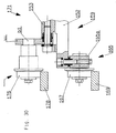
図23〜27は、複数のベーキングトング127が、水平な丸い回転テーブル126上に円軌道に沿って並んで配置されており、回転テーブル126の回転運動によって、円軌道に沿ってベーキングオーブンを通して運搬されるベーキングオーブン125を図示している。回転テーブル126は、垂直な回転軸128の周りを回転可能である。ベーキングオーブン125は、円軌道に沿って拡がるリング形状又は多角形の筐体129を有し、その筐体内には、ベーキングオーブン125のベーキング室130が配置されている。筐体129は、台座131に配置されている。多くの場合、筐体129は、ベーキングオーブン125の前側に構成される。筐体129の開いた領域には、ベーキングオーブン125の投入ステーションと排出ステーションが配置されている。筐体129の開いた領域には、円軌道に沿って配置されたガイドロッド132が配備されており、そのガイドロッドに沿って、ベーキングトング127が、その制御ローラー133を進めて、制御ローラー133によって開閉される。
FIGS. 23 to 27 show that a plurality of
各ベーキングトング127は、回転テーブル126と固定された下方のトング部分を有し、その下方のトング部分は、ヒンジ135によって、自由端で制御ローラー133を支持する上方のトング部分136と旋回可能な形で接続されている。下方のトング部分134には、サセプタプレート137として構成された下方のベーキングプレートが配置され、上方のトング部分136には、サセプタプレート138として構成された上方のベーキングプレートが配置されている。二つのサセプタプレート137,138は、それぞれベーキングトング127の外側に配置された、ベーキングプレートを非接触式に誘導加熱することが可能な裏面側と、ベーキングトング127の内部に配置された、上方又は下方のベーキングプレートのベーキング面を載せるための前面側とを有する。ベーキングトング127が閉じられている場合、サセプタプレート137,138は、水平方向を向いて重なっており、その前面側に置かれたベーキング面は、互いに対向している。
Each
ベーキングトング127は、回転テーブル126の回転運動によって、円軌道に沿ってベーキング室130を通して運搬される。ベーキング室130には、円軌道に沿って延びるベーキングゾーンが配設されている。そのゾーンでは、円軌道の上に、長く延びるアーチ形状の上方の誘導子139が配置され、円軌道の下に、長く延びるアーチ形状の下方の誘導子140が配置されている。二つの誘導子139,140は、大きな面積で幅の広い長く延びるアーチ形状に延びる磁界を発生させ、その磁界は、円軌道に沿って並んで配置された複数のベーキングトング127に渡って拡がっている。上方の誘導子139が発生する磁界は、そこから下方に向かってベーキングトング127の上方のトング部分にまで達し、そのトング部分で、サセプタプレート138として構成された上方のベーキングプレートを非接触式に誘導加熱する。下方の誘導子140が発生する磁界は、そこから上方に向かってベーキングトング127の下方のトング部分にまで達し、そのトング部分で、サセプタプレート137として構成された下方のベーキングプレートを非接触式に誘導加熱する。
The
上方の誘導子139は、筐体129内において、サセプタプレート138として構成された、閉じたベーキングトング127の上方のベーキングプレートの上に近接して配置されている。その誘導子は、筐体129内において、円軌道に対して交差して延びる上方の支持体141と固定されている。その誘導子は、並んで配置された四つの誘導子ストリップ139aを有する。これらの誘導子ストリップは、横断面全体が低い四角形である平坦な中空でないストリップとして構成されている。これらの平坦な誘導子ストリップ139aは、電気絶縁性の固定機器142によって、上方の支持体141と固定されている。固定機器142は、L字形状の固定ハンガー143を備えており、それらのハンガーの垂直に配置された上方の辺は、垂直方向に対して調整可能な形で支持体141と固定されている。平坦な誘導子ストリップ139aは、固定機器142の下端に配置されており、垂直な固定ネジ144によって、固定ハンガー143の水平に配置された下方の辺と固定されている。固定ネジ144と固定ハンガー143の下方の辺の間には、それぞれ電気絶縁性の複数のスペーサー145が配置されている(図25参照)。
The
下方の誘導子140は、筐体129内において、サセプタプレート137として構成された、閉じたベーキングトング127の下方のベーキングプレートの下に近接して配置されている。その誘導子は、筐体129内において、円軌道に対して交差して延びる下方の支持体146と固定されている。その誘導子は、並んで配置された四つの誘導子ストリップ140aを有する。これらの誘導子ストリップは、横断面全体が低い四角形である平坦な中空でないストリップとして構成されている。これらの平坦な誘導子ストリップ140aは、電気絶縁性の固定機器147によって、下方の支持体146と固定されている。固定機器147は、L字形状の固定ハンガー148を備えており、それらのハンガーの垂直に配置された下方の辺は、垂直方向に対して調整可能な形で支持体146と固定されている。平坦な誘導子ストリップ140aは、固定機器147の上端に配置されており、垂直な固定ネジ149によって、固定ハンガー148の水平に配置された上方の辺と固定されている。固定ネジ149と固定ハンガー148の下方の辺の間には、それぞれ電気絶縁性の複数のスペーサー150が配置されている(図26参照)。
The
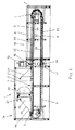
図28〜31は、それぞれ重ねて配置された二つのベーキングプレート152,153から成るベーキング押型内で焼いた成形食品を製造するためのベーキングオーブン151を図示している。これらのベーキング押型は、ベーキング室154において、水平なベーキング区間に沿って順番に配置されている。ベーキング区間は、ベーキングオーブン151の投入ステーション155からベーキング室154に配置されたベーキングゾーン156を通ってベーキングオーブン151の排出ステーション157にまで延びている。投入ステーション155では、一定量の生地が、ベーキング押型の下方のベーキングプレート152上に置かれる。上方のベーキングプレート153は、水平なベーキング区間158の始めで下方のベーキングプレート157上に降ろされ、そうすることによって、ベーキング押型を閉じる。排出ステーション157では、上方のベーキングプレート153は、下方のベーキングプレート152から引き上げられ、そうすることによって開いたベーキング押型から、焼き上がった成形食品が取り出される。
FIGS. 28 to 31 illustrate a
ベーキングオーブン151では、下方の巡回軌道に沿って配置された下方のベーキングプレート152を支持する下方のチェーンコンベヤー159が、水平なベーキング区間158の下に配置されている。下方の巡回軌道は、ベーキングオーブン151の下方部分を通る重ねて配置された二つの水平な運搬軌道160,161に沿って延びている。チェーンコンベヤー159の上側の運搬軌道160は、水平なベーキング区間158に沿って配置されており、チェーンコンベヤー159のベーキング部分を構成している。チェーンコンベヤー159の下側の運搬軌道161は、チェーンコンベヤー159のリターン部分を構成している。チェーンコンベヤー159は、二つの運搬軌道160,161に沿ってベーキングプレート152を運搬して、その前方と後方の端部で、チェーンホイールによって、一方の運搬軌道から他方の運搬軌道にベーキングプレートを方向転換している。
In the
チェーンコンベヤー159は、ベーキングオーブン151の長く延びるフレーム162内において、ベーキングオーブン151の下方部分のオーブンフレーム162の二つの側壁163,164の間に配置されている。チェーンコンベヤー159は、二つの側方の運搬チェーン165,166を有し、それらの間に、下方のベーキングプレート152が配置されている。運搬チェーン165,166は、側方に突き出た継手ボルトを備えており、その継手ボルトには、それぞれ動輪167,168が、回転可能な形で軸支されておりそれらの動輪によって、二つの運搬軌道160,161のチェーンコンベヤー159が、オーブンの長手方向に延びる、側壁163,164と固定されたガイドレール169で支持されている。運搬チェーン165,166は、プレートリンクチェーンとして構成されている。下方のベーキングプレート152の側方の終端部材は、二つの運搬チェーン165,166のチェーンプレート165a,166aと固定されている。下方のベーキングプレート152は、自由に動く裏面側が非接触式に誘導加熱可能であり、前面側で下方のベーキングプレート152のベーキング面を支持するサセプタプレートとして構成されている。チェーンプレート165a,166aと下方のベーキングプレート152の間には、電気絶縁性のスペーサー170が配置されており、そのスペーサーは、チェーンプレート165a,166aと下方のベーキングプレート152の間の金属の接触を防止している。
The
ベーキングオーブン151では、上方の巡回軌道に沿って配置された上方のベーキングプレート153を支持する上方のチェーンコンベヤー171が、水平なベーキング区間158の上に配置されている。上方の巡回軌道は、ベーキングオーブン151の上方部分を通る重ねて配置された二つの水平な運搬軌道172,173に沿って延びている。チェーンコンベヤー171の下側の運搬軌道172は、水平なベーキング区間158に沿って配置されており、チェーンコンベヤー171のベーキング部分を構成している。チェーンコンベヤー171の上側の運搬軌道173は、チェーンコンベヤー171のリターン部分を構成している。チェーンコンベヤー171は、二つの運搬軌道172,173に沿ってベーキングプレート153を運搬して、その前方と後方の端部で、チェーンホイールによって、一方の運搬軌道から他方の運搬軌道にベーキングプレートを方向転換している。
In the
上方のチェーンコンベヤー171は、二つの側方の終端部材174,175を有する。上方のベーキングプレート153は、二つの運搬チェーン174,175の間に配置されており、運搬チェーン174,175から内側に突き出たボルトb1,b2から自由に揺動する形で吊り下げられている。ベーキング面は、上方のベーキングプレート153の下方を向いた前面側に配置されている。上方のベーキングプレート153は、その側方の終端部材で、上方に突き出たハンガーg1,g2を支持しており、そのハンガーによって、上方のベーキングプレートが、運搬チェーン174,175のボルトb1,b2から自由に揺動する形で吊り下げられている。上方のベーキングプレート153は、重力によって、ベーキング面を下方に向けた姿勢で保持されている。上方のベーキングプレート153は、上方を向いた裏面側が非接触式に誘導加熱可能なサセプタプレートとして構成されている。サセプタプレートと上方のベーキングプレート153のハンガーg1,g2の間には、電気絶縁性のスペーサー176が配置されており、そのスペーサーは、ハンガーg1,g2と上方のベーキングプレート153の間の金属の接触を防止している。運搬チェーン174,175は、外側に突き出た継手ボルトを備えており、その継手ボルトには、それぞれ動輪176,177が回転可能な形で軸支されており、それらの動輪によって、二つの運搬軌道172,173のチェーンコンベヤー171が、オーブンの長手方向に延びる、オーブンフレーム162の側壁163,164と固定されたガイドレール178で支持されている。
The
ベーキングオーブン151は、誘導加熱部を備えている。この誘導加熱部は、ベーキングゾーン156に、長く延びる上方の誘導子179を備えており、その誘導子は、順番に配置された複数のベーキング押型に渡って拡がる、大きな面積で幅の広い長く延びる磁界を発生させる。上方の誘導子179は、水平なベーキング区間158に沿って配置されたベーキング押型の上に近接して配置されている。ベーキング押型の上側に配置された、サセプタプレートとして構成された上方のベーキングプレート153は、上方の誘導子179が発生する磁界によって、非接触式に誘導加熱される。誘導加熱部は、ベーキングゾーン156に、長く延びる下方の誘導子180を備えており、その誘導子は、順番に配置された複数のベーキング押型に渡って拡がる、大きな面積で幅の広い長く延びる磁界を発生させる。下方の誘導子180は、水平なベーキング区間158に沿って配置されたベーキング押型の下に近接して配置されている。ベーキング押型の下側に配置された、サセプタプレートとして構成された下方のベーキングプレート152は、下方の誘導子180が発生する磁界によって、非接触式に誘導加熱される。
The baking
更に、誘導加熱部は、二つのチェーンコンベヤー159,171のリターン部分171,173に配置された追加の誘導子181,182を備えている。
Further, the induction heating unit includes
下方のチェーンコンベヤー159のリターン部分161には、追加の誘導子181が配備されており、その誘導子は、順番に配置された複数の下方のベーキングプレート152に渡って拡がる、大きな面積で幅の広い長く延びる磁界を発生させる。この追加の誘導子181は、下方のベーキングプレート152の上方を向いた裏面側の上に配置されている。リターン部分161に配置された、サセプタプレートとして構成された下方のベーキングプレート152は、追加の誘導子181が発生する磁界によって、非接触式に誘導加熱される。
The
上方のチェーンコンベヤー171のリターン部分173には、別の追加の誘導子182が配備されており、その誘導子は、順番に配置された複数の上方のベーキングプレート153に渡って拡がる、大きな面積で幅の広い長く延びる磁界を発生させる。この追加の誘導子182は、上方のベーキングプレート153の上方を向いた裏面側の上に配置されている。リターン部分173に配置された、サセプタプレートとして構成された上方のベーキングプレート153は、追加の誘導子182が発生する磁界によって、非接触式に誘導加熱される。
The
誘導子179,180と追加の誘導子181,182は、それぞれ上方又は下方のベーキングプレート152,153の軌道に沿って順番に配置された複数の上方又は下方のベーキングプレート152,153に渡って拡がっている。誘導子179,180,181,182は、それぞれ幅の広い磁界を発生させ、その磁界は、ベーキングプレート152,153の巡回軌道に沿って順番に配置された複数のベーキングプレート152,153に渡って拡がるとともに、順番に配置された、サセプタプレートとして構成された複数のベーキングプレート152,153を非接触式に誘導加熱する。誘導子179,180,181,182は、様々な構造形態を採ることができる。それらは、図13〜17に図示された構造形態を採ることができる。誘導子179,180,181,182をベーキングオーブン151のフレーム162と固定する方法は、それぞれ図10〜12と関連して前述した固定方法と同じである。
図32〜34は、両側を焼いた平らな成形食品を製造するためのベーキング設備183を図示している。ベーキング設備183は、平らなパンケーキを製造して、下側を焼くための第一のベーキングオーブン184を備えている。第一のベーキングオーブン184には、裏返し機器185が繋がっている。そこでは、下側を焼かれたパンケーキが、上側を下して引っ繰り返され、そして上側を下にした状態で第二のベーキングオーブン186に渡されて、そこで、パンケーキは、第二の側を焼かれる。
FIGS. 32-34 illustrate a
第一のベーキングオーブン184では、平坦なベーキングプレート187が、巡回軌道に沿って配置されており、その巡回軌道は、ベーキングオーブン184を通る重ねて配置された二つの水平な運搬軌道188,189に沿って延びている。投入ステーション190は、下方の運搬軌道189に配置されている。投入ステーション190で、平らなパンケーキが作られる。そのために、液状のワッフル生地が、ベーキングプレート187の上方を向いたベーキング面上に置かれる。排出ステーション191は、ベーキングオーブン184の後端の上方の運搬軌道188に配置されている。排出ステーション191では、下側を焼かれたパンケーキが、ベーキングプレート187の上方を向いたベーキング面から取り出されて、裏返し機器185に渡される。
In the
ベーキングオーブン184は、平坦なベーキングプレート187の巡回軌道に沿って配置された、時計方向に回るチェーンコンベヤー192を有する。チェーンコンベヤー192は、ベーキングプレート187を二つの運搬軌道188,189に沿って運搬し、その前方と後方の端部で、チェーンホイールによって、一方の運搬軌道から他方の運搬軌道にベーキングプレートを方向転換している。チェーンコンベヤー192は、二つの側方の運搬チェーン193,194を有する。それらは、それぞれ継手ボルトが内側と外側で側方に突き出たプレートリンクチェーンとして構成されている。ベーキングプレート187は、二つの運搬チェーン193,194の間に配置されており、それぞれ運搬チェーンから内側に突き出た継手ボルト195,196の部分から、自由に揺動する形で吊り下げられている。ベーキング面は、ベーキングプレート187の上方を向いた前面側に配置されている。ベーキングプレート187は、その側方の終端部材で上方に突き出たハンガー197,198を支持している。これらのハンガー197,198によって、ベーキングプレートは、二つの運搬チェーン193,194から内側に突き出た継手ボルト195,196の部分から自由に揺動する形で吊り下げられている。ベーキングプレート187は、重力によって、ベーキング面を上方に向けた姿勢で保持されている。ベーキングプレート187は、下方を向いた裏面側を非接触式に誘導加熱可能なサセプタプレートとして構成されている。サセプタプレートとベーキングプレート187のハンガー197,198の間には、電気絶縁性のスペーサー199が配置されており、そのスペーサーは、ハンガー197,198とベーキングプレート187の間の金属の接触を防止している。二つの運搬チェーン193,194から外側に突き出た継手ボルト195,196の部分には、動輪200,201が回転可能な形で軸支されており、それらの動輪によって、二つの運搬軌道188,189のチェーンコンベヤー192が、オーブンの長手方向に延びる、オーブンフレーム204の側壁202,203に固定されたガイドレール205で支持されている。
ベーキングオーブン184では、ベーキング室206に二つのベーキングゾーンが配設されている。上方の運搬軌道188には、上方のベーキングゾーン207が配設され、下方の運搬軌道189には、下方のベーキングゾーン208が配設されている。ベーキングオーブン184は、誘導加熱部を備えている。それは、上方のベーキングゾーン207に、長く延びる誘導子209を備えており、その誘導子は、大きな面積で幅の広い長く延びる磁界を発生させ、その磁界は、順番に配置された、サセプタプレートとして構成された複数のベーキングプレート187に渡って拡がっている。誘導子209は、上方の運搬軌道188を通るベーキングプレート187の下に近接して配置されている。誘導加熱部は、下方のベーキングゾーン208に、長く延びる誘導子210を備えており、その誘導子は、大きな面積で幅の広い長く延びる磁界を発生させ、その磁界は、順番に配置された、サセプタプレートとして構成された複数のベーキングプレート187に渡って拡がっている。誘導子210は、下方の運搬軌道189を通るベーキングプレート187の下に近接して配置されている。
In the
誘導子209,210は、様々な構造形態を採ることができる。それらは、図13〜17に図示された構造形態を採ることができる。誘導子209,210は、そのような誘導子とは、並んで配置された誘導子ストリップの数が異なっている。誘導子209,210では、それぞれ26個の誘導子ストリップが並んで配置されている。誘導子209,210をベーキングオーブン184のフレームと固定する方法は、それぞれ図10〜12と関連して前述した固定方法と同じである。
The
第二のベーキングオーブン186では、平坦なベーキングプレート211が、巡回軌道に沿って配置されており、その巡回軌道は、ベーキングオーブン186を通る重ねて配置された二つの水平な運搬軌道211,213に沿って延びている。投入ステーション214は、ベーキングオーブン186の前端の上方の運搬軌道212に配置されている。投入ステーション214では、裏返し機器185から供給されて来たパンケーキが、ベーキングプレート211の上方を向いたベーキング面上に降ろされる。排出ステーション215は、ベーキングオーブン186の中央の上方の運搬軌道212に配置されている。排出ステーション215では、両側を焼かれたパンケーキが、ベーキングプレート211の上方を向いたベーキング面から取り出されて、ベーキング設備183から排出される。
In the
第二のベーキングオーブン186は、平坦なベーキングプレート211の巡回軌道に沿って配置された、反時計方向に回るチェーンコンベヤー216を有する。チェーンコンベヤー216の構造は、第一のベーキングオーブン184のチェーンコンベヤー192と同じである。チェーンコンベヤー216では、同様に、平坦なベーキングプレート211が、チェーンコンベヤー216の側方の運搬チェーンから自由に揺動する形で吊り下げられており、非接触式に誘導加熱可能なサセプタプレートとして構成されている。
The
第二のベーキングオーブン186は、誘導加熱部を備えており、その誘導加熱部は、二つの運搬軌道212,213に、それぞれ長く延びる誘導子217,218を備えており、その誘導子は、大きな面積で幅の広い長く延びる磁界を発生させ、その磁界は、順番に配置された、サセプタプレートとして構成された複数のベーキングプレート211に渡って拡がっている。誘導子217,218は、それぞれ運搬軌道212,213を通るベーキングプレート211の下に近接して配置されており、それらのベーキングプレートは、それぞれ誘導子217,218が発生する磁界によって非接触式に誘導加熱される。
The
誘導子217,218は、様々な構造形態を採ることができる。それらは、図13〜17に図示された構造形態を採ることができる。誘導子217,218は、そのような誘導子とは、並んで配置された誘導子ストリップの数が異なる。誘導子217,218では、それぞれ26個の誘導子ストリップが並んで配置されている。誘導子217,218をベーキングオーブン186のフレームと固定する方法は、それぞれ図10〜12と関連して前述した固定方法と同じである。
The
図35は、片側又は両側を焼いた平らな成形食品を製造するためのベーキングオーブン219を図示している。焼いた成形食品は、水平な回転テーブル221上に円軌道に沿って並んで配置されたベーキングプレート220で製造される。回転テーブル221は、垂直な回転軸222の周りを回転することが可能である。ベーキングプレート220は、回転テーブル221と固定されており、その外側の周縁部から半径方向に突き出ている。ベーキングプレート220は、回転テーブル221の回転運動によって、ベーキングオーブン219を通して動かされる。ベーキングオーブン219は、ベーキングプレート220の円軌道に沿って延びるとともに、ベーキング室224が中に配置されているリング形状又は多角形の筐体223を有する。ベーキングオーブン219の前面側では、筐体223は、開いた形で構成されている。筐体223の開いた領域には、ベーキングオーブン219の投入ステーション225と排出ステーション226が配置されている。投入ステーション225では、平らなパンケーキが作られる。そのために、液状のワッフル生地が、ベーキングプレート220の上方を向いたベーキング面上に置かれる。パンケーキを載せたベーキングプレート220は、回転テーブル221によって、ベーキング室224を通して運搬される。排出ステーション226では、焼き上がったパンケーキが、ベーキングプレート220から取り出されて、片側を焼かれたパンケーキとしてベーキングオーブン219から排出されるか、或いは両側を焼いたパンケーキを製造する場合には、直ぐにベーキング室224を通して第二の側も焼くように、上側を下にして引っ繰り返されて、再びベーキングプレート220上に置かれる。両側を焼かれるパンケーキは、ベーキング室224を二回通過し、二回目の通過後に初めて、排出ステーション226でベーキングオーブン219から排出される。
FIG. 35 illustrates a
ベーキングオーブン219のベーキングプレート220は、非接触式に誘導加熱可能なサセプタプレートとして構成されている。サセプタプレート220は、ベーキング室224で誘導加熱部227によって非接触式に誘導加熱される。サセプタプレート220は、その中に生じた熱を熱伝導によって、その上側に配置されたベーキング面に伝えて、その面の上でパンケーキを焼く。
The
誘導加熱部227は、円軌道に沿って配置された長く延びる誘導子228を少なくとも一つ備えており、その誘導子は、円軌道に沿って並んで配置された複数のベーキングプレート220に渡って拡がっている。誘導子228は、円軌道と交差する方向に並んで配置された、円軌道に沿って延びるアーチ形状に曲がった複数の誘導子ストリップ229を有する。誘導子228は、幅の広い磁界を発生し、その磁界は、円軌道に沿って並んで配置された複数のベーキングプレート220に渡って拡がるとともに、ベーキングプレートを非接触式に誘導加熱する。長く延びる誘導子228は、有利には、円軌道の下に、円軌道に対して平行に配置される。長く延びる誘導子228は、円軌道の上に配置することもできる。ベーキング室224において、そのような長く延びる誘導子228を円軌道の上と下に配置することもできる。
The
長く延びる誘導子228は、様々な構造形態で実現することができる。それは、図13〜17に図示された構造形態を採ることができる。誘導子228をベーキングオーブン219の筐体223と固定する方法は、図10〜12と関連して前述した固定方法と同じである。
The
Claims (41)
ベーキングプレートが、非接触式に誘導加熱可能なサセプタプレートとして構成されていることと、
ベーキング室には、誘導加熱部を備えたベーキングゾーンが配設されており、そのベーキングゾーンには、ベーキングプレートの巡回軌道に対して平行に配置された、巡回軌道に沿って複数のベーキングプレートに渡って拡がる長く延びる少なくとも一つの誘導子が配備されており、その誘導子が、大きな面積で幅の広い、巡回軌道に沿って複数のベーキングプレートに渡って拡がる磁界を発生させ、その磁界が、サセプタプレートとして構成された複数のベーキングプレートを同時に非接触式に誘導加熱することと、
を特徴とするベーキングオーブン。 In a baking oven comprising a loading station, a baking chamber, a discharging station, a baking plate arranged along a circular path through the baking chamber, and a conveying device for the baking plate,
The baking plate is configured as a susceptor plate capable of induction heating in a non-contact manner;
The baking room is provided with a baking zone having an induction heating unit, and the baking zone is arranged in parallel to the circular orbit of the baking plate, and is arranged in a plurality of baking plates along the circular orbit. There is provided at least one long extending inductor extending across the inductor, the inductor generating a magnetic field extending across a plurality of baking plates along a circular trajectory with a large area, the magnetic field being Inductively heating a plurality of baking plates configured as susceptor plates simultaneously in a non-contact manner;
Baking oven characterized by
二つの運搬軌道には、ベーキングゾーンが配設されており、そのベーキングゾーン内には、ベーキングプレートの巡回軌道に対して平行に配置された長く延びる少なくとも一つの誘導子が配備されており、その誘導子の磁界によって、サセプタプレートとして構成された複数のベーキングプレートを同時に非接触式に誘導加熱することと、
を特徴とする請求項1に記載のベーキングオーブン。 The baking plate is arranged along a circular trajectory passing through two horizontal conveying trajectories arranged in a stack;
The two transport tracks are provided with a baking zone, in which at least one long extending inductor arranged parallel to the circular trajectory of the baking plate is provided, Inductively heating a plurality of baking plates configured as susceptor plates simultaneously in a non-contact manner by the magnetic field of the inductor;
The baking oven according to claim 1.
ベーキング室には、ベーキングゾーンが配設されており、そのベーキングゾーンには、長く延びる少なくとも一つの誘導子が配備されており、その誘導子は、円形の巡回軌道に対して平行に配置されるとともに、円形の巡回軌道に沿ってサセプタプレートとして構成された複数のベーキングプレートに渡って拡がっていることと、
を特徴とする請求項1に記載のベーキングオーブン。 The baking plate is arranged along a circular circular trajectory and is fixed to a rotary table that can rotate around a vertical rotation axis, and this rotary table conveys the baking plate through the baking chamber by rotational movement. To do
The baking chamber is provided with a baking zone, and the baking zone is provided with at least one inductor that extends long, and the inductor is arranged in parallel to the circular circular trajectory. And extending across a plurality of baking plates configured as susceptor plates along a circular circuit path;
The baking oven according to claim 1.
ベーキング室には、少なくとも一つのベーキングゾーンが配設されており、そのベーキングゾーンでは、ベーキングトングの巡回軌道の上と下に、それぞれ少なくとも一つの長く延びる誘導子が配置されており、その誘導子の磁界によって、複数のベーキングトングのサセプタプレートを同時に非接触式に誘導加熱することと、
を特徴とする請求項1に記載のベーキングオーブン。 The baking oven is equipped with upper and lower baking plates, each configured as a susceptor plate, arranged along two circular trajectories through the baking chamber, which are accommodated in a baking tong. The baking tongs are placed along a circular path through the baking chamber and are transported in a closed state by the baking oven transporting equipment;
The baking room is provided with at least one baking zone, in which at least one long extending inductor is arranged above and below the circular path of the baking tong, and the magnetic field of the inductor. Inductively heating a plurality of baking tong susceptor plates simultaneously in a non-contact manner,
The baking oven according to claim 1.
ベーキング室では、円軌道に、少なくとも一つのベーキングゾーンが配設されており、そのベーキングゾーンでは、円軌道の上と下に、それぞれ少なくとも一つの長く延びるアーチ形状の誘導子が配置されており、その誘導子の磁界によって、複数のベーキングトングのサセプタプレートを同時に非接触式に誘導加熱することと、
を特徴とする請求項7に記載のベーキングオーブン。 A plurality of baking tongs arranged side by side along a circular path and fixed to a rotary table that can rotate about a vertical axis of rotation;
In the baking room, at least one baking zone is arranged on the circular track, and at least one long extending arch-shaped inductor is arranged above and below the circular track, respectively. Inductively heating the susceptor plates of multiple baking tongs simultaneously and non-contactingly by the magnetic field of the child
The baking oven according to claim 7.
二つの運搬軌道には、ベーキングゾーンが配設されており、そのベーキングゾーンでは、運搬軌道の上と下に、それぞれ少なくとも一つの長く延びる誘導子が配置されており、その誘導子の磁界によって、複数のベーキングトングのサセプタプレートを同時に非接触式に誘導加熱することと、
を特徴とする請求項7に記載のベーキングオーブン。 A baking tong configured to accommodate upper and lower baking plates configured as susceptor plates is disposed along a circular trajectory passing through two horizontally disposed transport tracks in the baking chamber;
The two transport tracks are provided with a baking zone. In the baking zone, at least one elongated inductor is disposed above and below the transport track. Inductively heating the baking tong susceptor plate at the same time,
The baking oven according to claim 7.
二つのトング部分内のサセプタプレートが、それぞれサセプタプレートの側面と繋がる二つの終端部材の間に配置されており、二つのトング部分のベーキングトングのヒンジ側に配置された終端部材は、ヒンジによって、互いに接続されており、上方のトング部分の自由端に配置された終端部材が、ベーキングトングを開閉するための制御ローラーを支持していることと、
を特徴とする請求項7から9までのいずれか一つに記載のベーキングオーブン。 In baking tongs, the upper tongue portion is pivotably connected to the lower tongue portion by a hinge,
The susceptor plates in the two tongue portions are respectively disposed between the two termination members connected to the side surfaces of the susceptor plate, and the termination members disposed on the hinge side of the baking tongues of the two tongue portions are A termination member connected to each other and disposed at the free end of the upper tongue portion supports a control roller for opening and closing the baking tongue;
The baking oven according to any one of claims 7 to 9, wherein
二つの巡回軌道が、投入ステーションからベーキング室を通って排出ステーションにまで通じる、ベーキング区間に沿って配置されたベーキング部分と、排出ステーションから戻って投入ステーションにまで通じるリターン部分とを有することと、
二つの巡回軌道のベーキング部分では、ベーキング区間に沿って配置されたサセプタプレートが、互いに対向するとともに、それぞれ上方と下方のベーキングプレートから成るベーキング押型を構成していることと、
ベーキング室には、少なくとも一つのベーキングゾーンが配設されており、そのゾーンでは、ベーキング区間に沿って配置されたベーキング押型の上と下に、それぞれ少なくとも一つの長く延びる誘導子が配置されており、その誘導子の磁界によって、複数のベーキング押型のサセプタプレートを同時に非接触式に誘導加熱することと、
を特徴とする請求項1に記載のベーキングオーブン。 Arranged as two susceptor plates arranged along two circular trajectories through the baking chamber, with upper and lower baking plates arranged on two separate chain conveyors;
The two trajectories have a baking part arranged along the baking section leading from the charging station through the baking chamber to the discharging station and a return part returning from the discharging station to the charging station;
In the baking part of the two circular orbits, the susceptor plates arranged along the baking section are opposed to each other, and constitute baking molds composed of upper and lower baking plates, respectively.
In the baking room, at least one baking zone is arranged, and in that zone, at least one long extending inductor is arranged above and below the baking stamp arranged along the baking section, respectively. Inductively heating a plurality of baking stamp susceptor plates simultaneously in a non-contact manner by the magnetic field of the inductor;
The baking oven according to claim 1.
ベーキング室には、水平なベーキング区間に沿って延びるベーキングゾーンが配設されており、そのベーキングゾーンは、ベーキング押型の上に配置された長く延びる少なくとも一つの上方の誘導子と、ベーキング押型の下に配置された長く延びる下方の誘導子とを有することと、
を特徴とする請求項20に記載のベーキングオーブン。 The upper and lower baking plates configured as susceptor plates are arranged along two circular trajectories, in which the baking part is arranged along a horizontal baking section;
The baking chamber is provided with a baking zone extending along a horizontal baking section, the baking zone comprising at least one long extending inductor disposed above the baking mold and under the baking mold. Having a long extending lower inductor disposed on the
The baking oven according to claim 20.
下方のベーキングプレートは、下方の巡回軌道に沿って配置されるとともに、下方のチェーンコンベヤーによって、ベーキング区間を通して運搬されることと、
上方のベーキングプレートは、上方のチェーンコンベヤーによって、ベーキング区間の始めで下方のベーキングプレート上に降ろされて、ベーキング区間の終わりで下方のベーキングプレートから引き上げられることと、
下方のチェーンコンベヤーが、それぞれ下方のベーキングプレートとその上に降ろされる上方のベーキングプレートとから成るベーキング押型をベーキング区間に沿ってベーキングゾーンを通して運搬することと、
を特徴とする請求項21に記載のベーキングオーブン。 The upper baking plate is arranged along the upper circular path, and is hung in such a manner as to freely swing from the upper chain conveyor with its baking surface directed downward.
The lower baking plate is disposed along the lower circular track and is transported through the baking section by the lower chain conveyor;
The upper baking plate is lowered by the upper chain conveyor onto the lower baking plate at the beginning of the baking section and pulled up from the lower baking plate at the end of the baking section;
A lower chain conveyor transports a baking mold, each consisting of a lower baking plate and an upper baking plate lowered thereon, along the baking section through the baking zone;
The baking oven according to claim 21.
その互いに平行に延びる誘導子ストリップが、その端部を横方向のストリップによって接続されるとともに、その横方向のストリップと共に、誘導子の長手方向に長く延びる螺旋体を構成することと、
を特徴とする請求項28に記載のベーキングオーブン。 The long extending inductor is configured as a single inductor loop;
The inductor strips extending parallel to each other are connected at their ends by a lateral strip and together with the lateral strip constitute a spiral extending longitudinally in the longitudinal direction of the inductor;
The baking oven according to claim 28.
その互いに平行に延びる誘導子ストリップは、その端部を横方向のストリップによって交互に互いに接続されるとともに、その横方向のストリップと共に、蛇行したループが誘導子の長手方向と交差する方向に対して連続して延びる蛇行パターンを形成していることと、
を特徴とする請求項28に記載のベーキングオーブン。 The long extending inductor is configured as a single inductor loop;
The mutually extending inductor strips are connected to each other at their ends alternately by lateral strips, and with the lateral strips, in the direction in which the meandering loop intersects the longitudinal direction of the inductors. Forming a continuously extending meandering pattern;
The baking oven according to claim 28.
Applications Claiming Priority (3)
| Application Number | Priority Date | Filing Date | Title |
|---|---|---|---|
| ATA225/2008 | 2008-02-12 | ||
| AT0022508A AT506418B1 (en) | 2008-02-12 | 2008-02-12 | OVEN WITH INDUCTION HEATING |
| PCT/EP2009/000906 WO2009100873A2 (en) | 2008-02-12 | 2009-02-10 | Oven |
Publications (2)
| Publication Number | Publication Date |
|---|---|
| JP2011517930A true JP2011517930A (en) | 2011-06-23 |
| JP2011517930A5 JP2011517930A5 (en) | 2013-10-17 |
Family
ID=40957308
Family Applications (1)
| Application Number | Title | Priority Date | Filing Date |
|---|---|---|---|
| JP2010545415A Pending JP2011517930A (en) | 2008-02-12 | 2009-02-10 | Baking oven |
Country Status (9)
| Country | Link |
|---|---|
| EP (1) | EP2303027B1 (en) |
| JP (1) | JP2011517930A (en) |
| KR (1) | KR20100126740A (en) |
| CN (1) | CN102014640B (en) |
| AT (1) | AT506418B1 (en) |
| CA (1) | CA2714468C (en) |
| RU (1) | RU2504155C2 (en) |
| TR (1) | TR201905239T4 (en) |
| WO (1) | WO2009100873A2 (en) |
Cited By (1)
| Publication number | Priority date | Publication date | Assignee | Title |
|---|---|---|---|---|
| JP2014526889A (en) * | 2011-08-18 | 2014-10-09 | ハース・フード・イクイップメント・ゲゼルシャフト・ミト・ベシュレンクテル・ハフツング | Baking plate for baking kiln |
Families Citing this family (10)
| Publication number | Priority date | Publication date | Assignee | Title |
|---|---|---|---|---|
| AT511404B1 (en) * | 2011-05-11 | 2015-10-15 | Haas Food Equipment Gmbh | OVEN |
| AT511403B1 (en) * | 2011-05-11 | 2015-10-15 | Haas Food Equipment Gmbh | OVEN |
| AT511407B1 (en) * | 2011-05-11 | 2014-02-15 | Franz Haas Waffel Und Keksanlagen Ind Gmbh | DEVICE AND METHOD FOR PRODUCING WAFFLE BLOCKS |
| AT511408B1 (en) * | 2011-05-11 | 2017-04-15 | Haas Food Equipment Gmbh | OVEN WITH A FINAL BACKBAND |
| CN102151095A (en) * | 2011-05-23 | 2011-08-17 | 宣伯民 | Continuous egg frying device |
| CN105746618B (en) * | 2015-11-17 | 2019-06-11 | 广东肇庆市科华食品机械实业有限公司 | A kind of wet mash secondary mould closing mechanism |
| CA3005655A1 (en) | 2015-11-17 | 2017-05-26 | Gea Food Solutions Bakel B.V. | Oven with improved drag |
| EP3721712A1 (en) * | 2019-04-12 | 2020-10-14 | Haas Food Equipment GmbH | Baking device and production system |
| RU2756122C1 (en) * | 2021-03-16 | 2021-09-28 | Михаил Витальевич Сорокин | Device for manufacturing confectionery products (options) |
| EP4275499A1 (en) * | 2022-05-11 | 2023-11-15 | Bühler Food Equipment GmbH | Backing plate device, baking apparatus and baking sheet |
Citations (5)
| Publication number | Priority date | Publication date | Assignee | Title |
|---|---|---|---|---|
| JPS4997342A (en) * | 1973-01-23 | 1974-09-13 | ||
| JPH01132091U (en) * | 1988-03-03 | 1989-09-07 | ||
| JPH0556742A (en) * | 1991-02-05 | 1993-03-09 | Chugoku Electric Power Co Inc:The | Induction heating type baking device of cakes |
| JPH09271358A (en) * | 1996-04-05 | 1997-10-21 | Bibun Corp | Apparatus for continuously frying eggroll |
| JPH1023853A (en) * | 1996-07-11 | 1998-01-27 | Yamada Seisakusho:Kk | Food baking machine |
Family Cites Families (20)
| Publication number | Priority date | Publication date | Assignee | Title |
|---|---|---|---|---|
| US3187152A (en) * | 1962-03-19 | 1965-06-01 | Itoya Kuaio | Heating conveyor delt |
| IL39641A (en) * | 1971-06-10 | 1974-10-22 | Toyo Kogyo Co | Oil seal construction for rotary internal combustion engine |
| AT381623B (en) * | 1981-05-11 | 1986-11-10 | Haas Franz Waffelmasch | WAFFLE OVEN WITH AN ENDLESS CONTINUOUS BAKING TONG CHAIN, ESPECIALLY FOR WAFFLE PRODUCTS, SUCH AS Flat waffles, lower hollow waffles, sugar bags, waffle cups and waffle figures |
| DE3446260A1 (en) * | 1984-12-19 | 1986-07-03 | Tauch Technik Service GmbH, 5000 Köln | Electric smelting furnace, especially induction furnace |
| FR2623691B1 (en) * | 1987-12-01 | 1990-03-09 | Electricite De France | APPARATUS FOR COOKING LOW THICKNESS DISHES SUCH AS OMELETTES, QUICHES OR THE LIKE |
| AU646787B3 (en) * | 1993-07-27 | 1994-03-03 | Penny Hlavaty | Cooking arrangements |
| HU219563B (en) * | 1994-05-27 | 2001-05-28 | Franz Haas Waffelmaschinen Industriegesellschaft M.B.H. | Process and device for producing formed wafer products, mainly rolled wafer cones |
| AT411955B (en) * | 1999-05-04 | 2004-08-26 | Haas Franz Waffelmasch | BAKING DEVICE FOR PRODUCING ENDLESS BELTS |
| ES2324812T3 (en) * | 2000-02-10 | 2009-08-17 | Wegra Beheer B.V. | APPARATUS FOR COOKING OVEN EDIBLE PRODUCTS. |
| CN1284417C (en) * | 2001-07-04 | 2006-11-08 | 味之素株式会社 | Heating device and heating stabilizer used on same |
| RU22338U1 (en) * | 2001-07-25 | 2002-03-27 | Общество с ограниченной ответственностью "Машиностроительный завод "Стандарт" | AUTOMATED FURNACE FOR MANUFACTURING BAKED WAFFLE SHEETS |
| US6866033B2 (en) * | 2001-09-14 | 2005-03-15 | Fmc Technologies Inc. | Cooking oven damper system for regulating upper and lower flow paths |
| JP4146670B2 (en) * | 2002-06-05 | 2008-09-10 | 北陸電機製造株式会社 | High frequency induction heating device |
| ITMI20021818A1 (en) * | 2002-08-09 | 2004-02-10 | De Longhi Spa | ELECTRICALLY POWERED OVEN IN PARTICULAR FOR THE |
| JP4260503B2 (en) * | 2003-02-14 | 2009-04-30 | 日世株式会社 | Cleaning method of molding machine |
| AT500219B1 (en) * | 2003-05-22 | 2007-11-15 | Masterfoods Austria Ohg | METHOD AND DEVICE FOR HEAT TREATMENT OF FOODSTUFFS BZW. FEEDINGSTUFFS, ESPECIALLY FOR THE MANUFACTURE OF BAKERY PRODUCTS, SUCH AS WAFFLE PRODUCTS |
| SE526553C2 (en) * | 2003-07-18 | 2005-10-04 | Inter Ikea Systems Bv | Device for making omelets and ways of making omelets in the device |
| CN1813545A (en) * | 2005-02-02 | 2006-08-09 | 温成德 | Constant temperature roaster with rotating device |
| EP1880646B1 (en) * | 2006-07-21 | 2010-04-14 | Schmalz Distributions-Systeme AG | Device for providing food and method for providing prepared food |
| DE102006044593A1 (en) * | 2006-09-19 | 2008-03-27 | Miwe Michael Wenz Gmbh | oven |
-
2008
- 2008-02-12 AT AT0022508A patent/AT506418B1/en active
-
2009
- 2009-02-10 CN CN200980105057.5A patent/CN102014640B/en active Active
- 2009-02-10 EP EP09711082.9A patent/EP2303027B1/en active Active
- 2009-02-10 WO PCT/EP2009/000906 patent/WO2009100873A2/en active Application Filing
- 2009-02-10 KR KR1020107020437A patent/KR20100126740A/en not_active Application Discontinuation
- 2009-02-10 RU RU2010132680/13A patent/RU2504155C2/en not_active IP Right Cessation
- 2009-02-10 CA CA2714468A patent/CA2714468C/en not_active Expired - Fee Related
- 2009-02-10 TR TR2019/05239T patent/TR201905239T4/en unknown
- 2009-02-10 JP JP2010545415A patent/JP2011517930A/en active Pending
Patent Citations (5)
| Publication number | Priority date | Publication date | Assignee | Title |
|---|---|---|---|---|
| JPS4997342A (en) * | 1973-01-23 | 1974-09-13 | ||
| JPH01132091U (en) * | 1988-03-03 | 1989-09-07 | ||
| JPH0556742A (en) * | 1991-02-05 | 1993-03-09 | Chugoku Electric Power Co Inc:The | Induction heating type baking device of cakes |
| JPH09271358A (en) * | 1996-04-05 | 1997-10-21 | Bibun Corp | Apparatus for continuously frying eggroll |
| JPH1023853A (en) * | 1996-07-11 | 1998-01-27 | Yamada Seisakusho:Kk | Food baking machine |
Cited By (1)
| Publication number | Priority date | Publication date | Assignee | Title |
|---|---|---|---|---|
| JP2014526889A (en) * | 2011-08-18 | 2014-10-09 | ハース・フード・イクイップメント・ゲゼルシャフト・ミト・ベシュレンクテル・ハフツング | Baking plate for baking kiln |
Also Published As
| Publication number | Publication date |
|---|---|
| KR20100126740A (en) | 2010-12-02 |
| CA2714468C (en) | 2013-08-06 |
| CN102014640B (en) | 2014-10-15 |
| WO2009100873A3 (en) | 2011-01-27 |
| EP2303027B1 (en) | 2019-01-23 |
| CN102014640A (en) | 2011-04-13 |
| TR201905239T4 (en) | 2019-05-21 |
| RU2010132680A (en) | 2012-03-20 |
| EP2303027A2 (en) | 2011-04-06 |
| RU2504155C2 (en) | 2014-01-20 |
| WO2009100873A2 (en) | 2009-08-20 |
| AT506418B1 (en) | 2010-02-15 |
| CA2714468A1 (en) | 2009-08-20 |
| AT506418A1 (en) | 2009-09-15 |
Similar Documents
| Publication | Publication Date | Title |
|---|---|---|
| JP2011517930A (en) | Baking oven | |
| US8766148B2 (en) | Baking oven having inductors and susceptor plates | |
| US9930731B2 (en) | Induction cooking structure and system and method of using the same | |
| JP5161780B2 (en) | Equipment for heat treatment of packs | |
| JPH11264550A (en) | Oven, toaster, and oven toaster | |
| US20090320694A1 (en) | Induction wafer baking system | |
| JP2004515254A (en) | Baking furnaces that produce baked compacts | |
| US20050184061A1 (en) | Heating apparatus and heating stabilization device in thereof | |
| JP2011018511A (en) | Electromagnetic induction heater | |
| CN107361088B (en) | Tunnel type continuous superheated steam baking device | |
| JP2014513970A (en) | Oven with endless baking conveyor | |
| ITBO20070579A1 (en) | TUNNEL OVEN FOR FOODSTUFFS, IN PARTICULAR FOR BAKERY PRODUCTS, WHICH PIZZAS, FOCACCE AND SIMILAR. | |
| WO2016193957A1 (en) | Method and plant for the thermal treatment of friction elements, in particular brake pads | |
| JPS6355329B2 (en) | ||
| CN213153665U (en) | Baking equipment for producing nutrition bars | |
| JP5140743B2 (en) | Electromagnetic induction heating type food baking machine | |
| US4758442A (en) | Method of cooking | |
| EP4309501A1 (en) | Device for preparing pastry goods (embodiments) | |
| CN210842724U (en) | Oven for food production | |
| AT11114U1 (en) | OVEN WITH INDUCTION HEATING | |
| JPH0556742A (en) | Induction heating type baking device of cakes | |
| JP2778911B2 (en) | Food heating method and heating device | |
| EA045200B1 (en) | DEVICE FOR MANUFACTURING CONFECTIONERY PRODUCTS (OPTIONS) | |
| JP2004097399A (en) | Conveyor type fryer | |
| JPH11346725A (en) | Forming and heating method for paste food product |
Legal Events
| Date | Code | Title | Description |
|---|---|---|---|
| A621 | Written request for application examination |
Free format text: JAPANESE INTERMEDIATE CODE: A621 Effective date: 20110801 |
|
| A131 | Notification of reasons for refusal |
Free format text: JAPANESE INTERMEDIATE CODE: A131 Effective date: 20130305 |
|
| A601 | Written request for extension of time |
Free format text: JAPANESE INTERMEDIATE CODE: A601 Effective date: 20130604 |
|
| A602 | Written permission of extension of time |
Free format text: JAPANESE INTERMEDIATE CODE: A602 Effective date: 20130611 |
|
| A524 | Written submission of copy of amendment under section 19 (pct) |
Free format text: JAPANESE INTERMEDIATE CODE: A524 Effective date: 20130830 |
|
| A02 | Decision of refusal |
Free format text: JAPANESE INTERMEDIATE CODE: A02 Effective date: 20140121 |