JP2011517575A - Insertion system and lead for treatment of target tissue region - Google Patents
Insertion system and lead for treatment of target tissue region Download PDFInfo
- Publication number
- JP2011517575A JP2011517575A JP2010510934A JP2010510934A JP2011517575A JP 2011517575 A JP2011517575 A JP 2011517575A JP 2010510934 A JP2010510934 A JP 2010510934A JP 2010510934 A JP2010510934 A JP 2010510934A JP 2011517575 A JP2011517575 A JP 2011517575A
- Authority
- JP
- Japan
- Prior art keywords
- lead
- insertion tool
- target tissue
- tissue region
- curved
- Prior art date
- Legal status (The legal status is an assumption and is not a legal conclusion. Google has not performed a legal analysis and makes no representation as to the accuracy of the status listed.)
- Pending
Links
Images


Classifications
-
- A—HUMAN NECESSITIES
- A61—MEDICAL OR VETERINARY SCIENCE; HYGIENE
- A61N—ELECTROTHERAPY; MAGNETOTHERAPY; RADIATION THERAPY; ULTRASOUND THERAPY
- A61N1/00—Electrotherapy; Circuits therefor
- A61N1/02—Details
- A61N1/04—Electrodes
- A61N1/05—Electrodes for implantation or insertion into the body, e.g. heart electrode
- A61N1/0526—Head electrodes
- A61N1/0529—Electrodes for brain stimulation
- A61N1/0534—Electrodes for deep brain stimulation
Abstract
本開示内容は、目標組織領域と順応するために目標の解剖学的構造を通じたリード(例えば脳治療の体制で用いられるようなもの)の挿入を可能にするシステム及び方法を提供するものである。模範的リードは、目標組織領域により規定される幾何学的構造に順応するための少なくとも一部が湾曲した部分を含む。模範的実施例において、このシステムは、印加される電界の改善された術後操作のために脳内の目標を刺激することに関する。このリードは、予め湾曲させられたものとするか、又は挿入軌道の或る特定の湾曲が達成されるように挿入中に機械的横歪みにかけられることができる。本システムは、挿入中にリードに対する案内及び機械的支持をなすためにリードに対して除去可能に係合させられる少なくとも第1の挿入ツールを含む。 The present disclosure provides systems and methods that allow for the insertion of a lead (eg, as used in a brain treatment regime) through a target anatomy to accommodate a target tissue region. . The exemplary lead includes at least a portion that is curved to conform to the geometric structure defined by the target tissue region. In an exemplary embodiment, the system relates to stimulating a target in the brain for improved post-operative manipulation of the applied electric field. This lead can be pre-curved or subjected to mechanical lateral strain during insertion so that a certain curvature of the insertion trajectory is achieved. The system includes at least a first insertion tool that is removably engaged with the lead to provide guidance and mechanical support for the lead during insertion.
Description
本開示内容は、解剖学的構造の目標組織領域により規定される幾何学的構造とその目標組織領域の治療とに適合するためのリードの配置を可能にするためのシステム及び方法に関する。 The present disclosure relates to systems and methods for enabling placement of leads to conform to a geometric structure defined by a target tissue region of an anatomical structure and treatment of the target tissue region.
移植可能な脳神経刺激装置は、パーキンソン病、運動障害及び癲癇を含む幾つかの治療のための臨床診療に益々用いられてきている。さらに、現在の研究は、気分障害及び不安障害の治療のための神経刺激のための検査を含む。こうした装置は、特定の疾病の発現に関係した脳における或る特定の領域を刺激し又は抑制するための電気的刺激を用いる。医師らは、同様の治療効果を得るために脳構造の化学的又は光学的刺激の使用も考慮することができる。 Implantable cranial nerve stimulation devices are increasingly being used in clinical practice for several treatments, including Parkinson's disease, movement disorders, and epilepsy. In addition, current studies include tests for neural stimulation for the treatment of mood disorders and anxiety disorders. Such devices use electrical stimulation to stimulate or inhibit certain areas in the brain that are associated with the development of certain diseases. Physicians can also consider the use of chemical or optical stimulation of brain structures to obtain similar therapeutic effects.
現在の慣例は、しばしば、概して1ないし2mmの直径を有する柔軟性のあるケーブルから形成されるリードを用いる。さらに、かかるリードは、しばしば、図1に概略的に描かれるように、脳組織に供給されつつある電流の通じる複数の電気的接点を備えている。このようなリードは、直線的な案内管及び定位固定フレームに係合した機械的位置決めシステムを用いて患者の脳に位置づけられる。結果として、リードは、穿頭孔に対して直線に沿って移植されるのが普通である。 Current practice often uses leads formed from flexible cables, generally having a diameter of 1 to 2 mm. Further, such leads often comprise a plurality of electrical contacts through which electrical current is being delivered to brain tissue, as schematically depicted in FIG. Such a lead is positioned on the patient's brain using a mechanical positioning system engaged with a linear guide tube and stereotaxic frame. As a result, the lead is typically implanted along a straight line with respect to the burr hole.
残念ながら、位置付け及び/又は挿入後の刺激リードの直線形状は、しばしば、所望の治療効果を得るために刺激される予定とされた目標脳領域の形状と良好に合致せず、これに加え又はそうでなくとも効果的に当該形状に順応しないものとなる。これら領域は、通常、図1に示されるように、ある程度湾曲した形状、例えばU字状の海馬形状を規定するものである。さらに、印加される電界のステアリングは、横方向の磁場勾配しか生起できないので非常に限定されたものとなり、これにより、刺激すべき神経組織のボリュームを選択する能力を大幅に制限することになる。 Unfortunately, the linear shape of the stimulation lead after positioning and / or insertion often does not match well with the shape of the target brain region intended to be stimulated to obtain the desired therapeutic effect, in addition to or Otherwise, it will not adapt to the shape effectively. These regions usually define a shape that is curved to some extent, for example, a U-shaped hippocampal shape, as shown in FIG. In addition, the steering of the applied electric field is very limited because only lateral magnetic field gradients can occur, which greatly limits the ability to select the volume of neural tissue to be stimulated.
米国特許出願に係る文献のU.S.6,343,226には、移植可能なパルス発生器に接続される二次関数極深部脳刺激電極を用いて、例えば、パーキンソン病、癲癇、精神病及び難治性疼痛に見られるもののような中枢神経及び末梢神経系の障害による症状を治療するための電気刺激を展開した技術が記述されている。電極装置は、同時微小電極記録との組み合わせで大きな体積の神経組織の刺激を可能にするものが設けられる。他の特徴は、仮設の電気−生理学的マイクロレコーディング微小電極/スチレット1、湾曲した電極先端、分離した電極先端又は非対称電気刺激場を含む。この技術は、永続的深部脳刺激電極の配置との組み合わせで微小電極記録により最適神経刺激領域の外傷性の低い位置特定を見越すものである。 U.S. Patent Literature relating to US patent applications. S. No. 6,343,226 uses a quadratic deep brain stimulation electrode connected to an implantable pulse generator, for example, central centers such as those found in Parkinson's disease, epilepsy, psychosis and refractory pain. Techniques have been described that have developed electrical stimulation to treat symptoms due to nerve and peripheral nervous system disorders. Electrode devices are provided that allow stimulation of large volumes of neural tissue in combination with simultaneous microelectrode recording. Other features include a temporary electro-physiological microrecording microelectrode / stiletto 1, a curved electrode tip, a separate electrode tip or an asymmetric electrical stimulation field. This technique allows for low traumatic localization of the optimal neurostimulation region by microelectrode recording in combination with permanent deep brain stimulation electrode placement.
米国特許出願に係る文献のU.S.7,033,326には、脳刺激のためのリードを移植するシステム及び方法が記述されている。リード及び導入ツールは、深部脳刺激及び他の用途のために提案されている。幾つかの実施例は、探り針とともに置かれることのできるリードデザインを提供するものであり、他のものは探り針を必要としない。幾つかのリードの実施例は、標準的なワイヤ導電体を用いるが、他のものはケーブル導電体を用いる。いくつもの実施例が、微小電極及び/又は微小電極組立体を組み込む。或る特定の実施例は、カニューレ及び/又はカニューレシステムのような導入ツールを提供するものであり、例えばリードの適切な位置づけを確実にするものである。 U.S. Patent Literature relating to US patent applications. S. 7,033,326 describes a system and method for implanting leads for brain stimulation. Lead and introducer tools have been proposed for deep brain stimulation and other applications. Some embodiments provide lead designs that can be placed with a probe, others do not require a probe. Some lead embodiments use standard wire conductors, while others use cable conductors. Several embodiments incorporate microelectrodes and / or microelectrode assemblies. Certain embodiments provide an introduction tool such as a cannula and / or cannula system, for example, to ensure proper positioning of the lead.
米国特許出願の2005/0137647は、刺激リードを組織に直接接触するよう経脈管的に送る方法を記述している。この出願によれば、患者の不調を治療する方法は、血管内に刺激リードを送ること、出口ポイントを形成するよう血管の壁を内腔より穴を開けること、そして刺激が当該不調を治療するところの組織に直接接触するよう当該出口ポイントを通じて刺激リードを導入することを含む。オプションとして、この方法は、患者の体の中に刺激のソースを埋め込むこと、そしてその埋め込まれた刺激ソースに刺激リードの近位端部を電気的に結合することを含む。かかる刺激リードを用いて、当該組織は、当該不調を治療するために刺激させられることができる。 US Patent Application 2005/0137647 describes a method of transvascularly delivering a stimulation lead to direct contact with tissue. According to this application, a method of treating a patient upset includes sending a stimulation lead into the blood vessel, piercing the vessel wall from the lumen to form an exit point, and the stimulation treats the upset. Including introducing a stimulation lead through the outlet point to directly contact the tissue. Optionally, the method includes implanting a source of stimulation in the patient's body and electrically coupling the proximal end of the stimulation lead to the implanted stimulation source. With such a stimulation lead, the tissue can be stimulated to treat the disorder.
米国特許出願の2006/0122677は、深部脳刺激電極のための様々な装置及び方法を記述している。この出願は、シャフトと、シャフトにおける少なくとも1つの開口部と、開口部を通じて周囲組織の中へシャフトから展開する少なくとも1つの伸張可能な巻きひげ部と、巻きひげ部に設けられた電極とを備えた展開深部脳刺激プローブを有する装置を記述している。 US patent application 2006/0122677 describes various devices and methods for deep brain stimulation electrodes. The application includes a shaft, at least one opening in the shaft, at least one expandable whisker that deploys from the shaft through the opening into the surrounding tissue, and an electrode provided on the whisker. A device having a deep brain stimulation probe is described.
米国特許出願の2006/0149335は、脳刺激のための装置及び方法を記述している。この出願は、長手状表面を備えたリードと、このリードの長手状表面に沿って設けられた少なくとも1つの刺激電極と、当該リードの長手状表面に沿って設けられ少なくとも1つの刺激電極から分離した少なくとも1つの記録電極とを含む脳刺激用装置を記述している。 US patent application 2006/0149335 describes an apparatus and method for brain stimulation. The application includes a lead having a longitudinal surface, at least one stimulation electrode disposed along the longitudinal surface of the lead, and separated from the at least one stimulation electrode disposed along the longitudinal surface of the lead. An apparatus for brain stimulation comprising at least one recording electrode.
米国特許出願の2004/0186544は、電気的組織刺激装置及び方法を記述している。この出願は、2次元又は3次元の電極を形成するよう開放組織スペースにおいて自らカールし戻す先端を有するワイヤ様延長可能部材を有する組織の電気的刺激のための移植可能なリードを記述している。電極は、リード本体から軸方向に又は別の方向に位置づけられることができる。リード本体又は延長可能な部材における牽引は、部材先端電極が巻き込み解除するので簡単に引き込み可能であり、大がかりな手術を伴うことなく除去することができる。 US Patent Application 2004/0186544 describes an electrical tissue stimulation device and method. This application describes an implantable lead for electrical stimulation of tissue having a wire-like extendable member with a tip that curls back in an open tissue space to form a two-dimensional or three-dimensional electrode. . The electrode can be positioned axially or in another direction from the lead body. The traction in the lead body or the extendable member can be easily retracted because the member tip electrode is unwound and can be removed without extensive surgery.
今日までの取り組みにもかかわらず、依然として、目標箇所に効果的に到達し係わり合いかつ治療することのできる効果的な挿入/リード組み合わせシステム及び方法に対して必要性が存在する。これらの必要性及びその他の必要性は、本開示内容のシステム及び方法により対処及び/又は克服される。 Despite efforts to date, there remains a need for an effective insertion / lead combination system and method that can effectively reach, engage and treat target locations. These needs and other needs are addressed and / or overcome by the systems and methods of the present disclosure.
本開示内容は、目標の解剖学的構造に関連した目標組織領域の治療のためのシステム及び方法を提供する。模範的な実施例において、目標組織挿入システムは、(a)目標の解剖学的構造に関連した目標組織領域にアクセスするよう適合したリードと、(b)このリードに取り外し可能に係合した少なくとも第1の挿入ツールと、を含む。この目標組織領域は、解剖学的構造を規定し、リードは、目標組織領域の解剖学的構造に従うように適合した湾曲部を規定する。当該挿入ツールは、目標組織領域に係合するよう目標の解剖学的構造の中へリードを挿入するよう適合される。この挿入ツールは、当該リードが目標組織領域に対して位置づけられると除去可能となる。 The present disclosure provides systems and methods for treatment of a target tissue region associated with a target anatomy. In an exemplary embodiment, the target tissue insertion system includes: (a) a lead adapted to access a target tissue region associated with the target anatomy; and (b) at least removably engaged with the lead. A first insertion tool. The target tissue region defines an anatomy, and the lead defines a bend adapted to follow the anatomy of the target tissue region. The insertion tool is adapted to insert a lead into the target anatomy to engage the target tissue region. The insertion tool can be removed once the lead is positioned relative to the target tissue region.
挿入ツールは、挿入の間、リードに対して案内及び機械的支持を提供するよう適合させられる。模範的な実施例において、このリードは、目標組織領域を刺激すること、目標組織領域に関連した活動を記録すること、薬剤及び/又は化学物質を目標組織領域に搬送することからなるグループから選択される機能を行うよう目標組織領域をアクセスする。このリードは、目標組織領域の幾何学的構造に合致するよう予め湾曲させられ、かなり硬直したものとなるよう構成されることができる。或いは、リードは、かなりソフトで柔軟性があるように構成され、目標の解剖学的構造の中へ挿入された後に目標組織領域の幾何学的構造に合致するよう曲がるよう適合させられることができる。模範的実施例において、目標組織領域は、患者の頭蓋骨の中に閉じられた脳の少なくとも一部である。 The insertion tool is adapted to provide guidance and mechanical support for the lead during insertion. In an exemplary embodiment, the lead is selected from the group consisting of stimulating the target tissue area, recording activity associated with the target tissue area, and delivering drugs and / or chemicals to the target tissue area. Access the target organization area to perform the function This lead can be configured to be pre-curved and fairly stiff to match the geometric structure of the target tissue region. Alternatively, the lead can be configured to be fairly soft and flexible and adapted to bend to conform to the geometry of the target tissue region after insertion into the target anatomy. . In an exemplary embodiment, the target tissue region is at least a portion of the brain closed in the patient's skull.
この開示内容は、ほぼリードを取り巻くよう当該リードに対して外部から位置づけられる模範的な挿入ツールを提供するものである。この挿入ツールは、リードを目標組織領域に案内し頭蓋骨を貫通させないように、或いはリードを目標組織領域に案内し頭蓋骨を貫通するように適合させられることが可能である。模範的実施例において、この挿入ツールの断面は、第1の幾何学的構造を規定し、挿入ツールにより取り巻かれるリードの断面は、第2の幾何学的構造を規定し、第1及び第2の幾何学的構造は、幾何学的関係を規定する。第1の幾何学的構造と第2の幾何学的構造との関係は、相似又は非回転対称のものとすることができる。模範的実施例において、第1の幾何学的構造は、円形であり、第2の幾何学的構造は、四角形、長円形及び三角形からなるグループから選択される。 This disclosure provides an exemplary insertion tool that is positioned externally relative to the lead to generally surround the lead. The insertion tool can be adapted to guide the lead to the target tissue region and not penetrate the skull, or to guide the lead to the target tissue region and penetrate the skull. In an exemplary embodiment, the cross section of the insertion tool defines a first geometric structure, and the cross section of the lead surrounded by the insertion tool defines a second geometric structure, the first and second The geometric structure defines a geometric relationship. The relationship between the first geometric structure and the second geometric structure can be similar or non-rotationally symmetric. In an exemplary embodiment, the first geometric structure is a circle and the second geometric structure is selected from the group consisting of a square, an oval, and a triangle.
この開示内容は、円形の幾何学的構造及びコルクスクリュー/螺旋の幾何学的構造の孤からなるグループから選択される幾何学的構造を規定するよう湾曲した模範的リードを提供するものである。これら幾何学的構造を規定するリードは、当該リードの全ての部分がリード先端と同じ経路に従うように挿入の間において目標の幾何学的構造を通る経路に沿って移動するリード先端を規定するのが普通である。模範的実施例において、このリードは、遠位端において開口を近位端において閉じた部分を有するほぼ管状のものであり、少なくとも第1の挿入ツールは、当該リードに対して内部に位置づけられる。当該少なくとも第1の挿入ツールは、ガイドワイヤなど、目標組織領域に対してリードを順応させることの可能な挿入ツールとすることができる。 This disclosure provides an exemplary lead that is curved to define a geometric structure selected from the group consisting of a circular geometry and an arc of a corkscrew / spiral geometry. These geometric defining leads define a lead tip that moves along a path through the target geometry during insertion so that all portions of the lead follow the same path as the lead tip. Is normal. In the exemplary embodiment, the lead is generally tubular with an opening at the distal end and a closed portion at the proximal end, and at least the first insertion tool is positioned internally relative to the lead. The at least first insertion tool can be an insertion tool such as a guidewire that can adapt the lead to the target tissue region.
模範的実施例において、第1の挿入ツールは、リードに対して内部に位置づけられ、システムはさらに、第1の挿入ツールを取り囲んでリードに対して内部に位置づけられる第2の挿入ツールを含む。模範的実施例において、第1の挿入ツールは、ガイドワイヤとすることができ、第2の挿入ツールは、シリンジ又はカニューレとすることができる。第1の挿入ツールの断面は、第1の幾何学的構造を規定し、第1の挿入ツールを取り巻く第2の挿入ツールの断面は、第2の幾何学的構造を規定する。第1及び第2の幾何学的構造は、相似のものとすることができ、或いは円対称性の関係を規定することができる。模範的実施例において、第2の幾何学的構造は、円形であり、第1の幾何学的構造は、四角形、長円形及び三角形からなるグループから選択される。 In an exemplary embodiment, the first insertion tool is positioned internally with respect to the lead, and the system further includes a second insertion tool surrounding the first insertion tool and positioned internally with respect to the lead. In an exemplary embodiment, the first insertion tool can be a guide wire and the second insertion tool can be a syringe or cannula. The cross section of the first insertion tool defines a first geometric structure, and the cross section of the second insertion tool surrounding the first insertion tool defines a second geometric structure. The first and second geometric structures can be similar, or can define a circular symmetry relationship. In the exemplary embodiment, the second geometric structure is circular and the first geometric structure is selected from the group consisting of a square, an oval, and a triangle.
本開示内容は、リード及び少なくとも第1の挿入ツールが相似の湾曲した部分を規定するような模範的なシステムを提供するものである。模範的実施例において、リードは、予め湾曲させられており、直線状部分と湾曲部分とを含み、当該湾曲部分が目標組織領域に対して近位端にあり当該直線状部分が目標組織領域に対して遠位端にあるようなものとしている。他の模範的実施例において、当該少なくとも第1の挿入ツールは、ほぼ直線状であり、リードに対して外側に位置づけられている。湾曲部は、さらに挿入されて目標組織領域に到達しこれによりほぼ湾曲した軌道経路に従うことになるまで当該湾曲部を暫定的に直線状にさせて挿入ツールに対して内部に留まる。模範的実施例において、当該少なくとも第1の挿入ツールは、リードに対して内部に位置づけられるガイドワイヤであり、当該少なくとも第1の挿入ツールは、目標組織領域に対して遠位端におけるほぼ直線状の部分と、目標組織領域に対して近位端にある湾曲部とを含む。 The present disclosure provides an exemplary system in which the lead and at least the first insertion tool define a similar curved portion. In an exemplary embodiment, the lead is pre-curved and includes a straight portion and a curved portion, the curved portion being proximal to the target tissue region and the straight portion being at the target tissue region. On the other hand, it seems to be at the distal end. In another exemplary embodiment, the at least first insertion tool is generally straight and positioned outwardly with respect to the lead. The curved portion remains inserted with respect to the insertion tool until it is further inserted to reach the target tissue region and thereby follow a substantially curved trajectory path, thereby making the curved portion tentatively straight. In an exemplary embodiment, the at least first insertion tool is a guidewire positioned internally with respect to the lead, and the at least first insertion tool is generally straight at the distal end relative to the target tissue region. And a bend at the proximal end relative to the target tissue region.
本開示内容は、かなりソフトで柔軟性のあるものとするように構成され、直線状部と湾曲部とを含むリードを有する模範的システムを提供するものであり、湾曲部が目標組織領域に対して近位端にあり、直線状部が目標組織領域に対して遠位端にあるようにしたものである。本システムは、リードに対して内部に移動可能に位置づけられる第1の挿入ツールを取り巻く第2の挿入ツールを含むことができる。この第2の挿入ツールは、ほぼ直線状の軌道を規定するほぼ硬直したものとなるように構成可能である。ほぼ硬直した第2の挿入ツールに対して、第1の挿入ツール及びリードは、挿入の間に当該硬直した第2の挿入ツールにより真っ直ぐにされて、第2の挿入ツールが除去されるにつれて相当に湾曲した軌道経路に沿って移動する。模範的実施例において、本開示内容によるシステムは、目標組織領域に達するための挿入ツール及びリードの挿入のサポートをなすための位置決めサポート装置を含むことができる。 The present disclosure provides an exemplary system configured to be fairly soft and flexible and having a lead that includes a straight portion and a curved portion, where the curved portion is relative to a target tissue region. At the proximal end and with the straight section at the distal end relative to the target tissue region. The system can include a second insertion tool surrounding a first insertion tool that is movably positioned inward relative to the lead. The second insertion tool can be configured to be substantially rigid that defines a substantially linear trajectory. For a second insertion tool that is substantially rigid, the first insertion tool and lead are straightened by the second insertion tool that has been rigid during insertion and correspondingly removed as the second insertion tool is removed. Move along a curved path. In an exemplary embodiment, a system according to the present disclosure may include an insertion tool to reach a target tissue region and a positioning support device to support lead insertion.
模範的実施例において、少なくとも第1の挿入ツールは、ガイドワイヤとされ、ほぼ螺旋の又はコルク抜き形態の幾何学的構造を規定する。他の模範的実施例において、このリードは、略螺旋状又はコルク抜き状の幾何学的構造を規定する。この少なくとも第1の挿入ツールは、リードに対して内部に位置づけられるガイドワイヤとすることができ、当該少なくとも第1の挿入ツールは、目標組織領域に対して遠位端にほぼ直線状部分を、目標組織領域に対して近位端に螺旋又はコルク抜き形態の部分を含むことができる。当該リードは、目標組織領域に対して遠位端にほぼ直線状部分を、目標組織領域に対して近位端に螺旋又はコルク抜き形態の部分を含むことができる。 In an exemplary embodiment, at least the first insertion tool is a guide wire and defines a generally helical or corkscrew shaped geometric structure. In other exemplary embodiments, the lead defines a generally spiral or corkscrew geometry. The at least first insertion tool can be a guidewire positioned internally with respect to the lead, the at least first insertion tool having a generally linear portion at a distal end relative to the target tissue region, A portion in the form of a spiral or corkscrew may be included at the proximal end relative to the target tissue region. The lead can include a generally straight portion at the distal end relative to the target tissue region and a portion in a spiral or corkscrew configuration at the proximal end relative to the target tissue region.
模範的実施例において、このリードはさらに、挿入の間、少なくともリードの遠位端において機械的横歪みを誘発させるためのほぼ長手方向においてリードを通過する複数のワイヤを含むことができる。当該少なくとも第1の挿入ツールはさらに、挿入の間に少なくとも第1の挿入ツールの遠位端において機械的横歪みを誘発させるためのほぼ長手方向において当該挿入ツールを通過する複数のワイヤを含む。 In an exemplary embodiment, the lead can further include a plurality of wires passing through the lead in a substantially longitudinal direction to induce mechanical lateral strain at least at the distal end of the lead during insertion. The at least first insertion tool further includes a plurality of wires passing through the insertion tool in a substantially longitudinal direction for inducing mechanical lateral strain at least at a distal end of the first insertion tool during insertion.
本開示内容は、リードの目標組織領域への挿入をなし前記目標組織領域の幾何学的構造との順応をなすための方法であって、(a)既に湾曲したリードを用意し、又は未だ湾曲していないリードに湾曲した軌道を誘発させるステップと、(b)前記リードに対して少なくとも第1の挿入ツールを除去可能に係合させるステップと、(c)前記目標組織領域に到達するよう目標の解剖学的構造を通じて前記リード及び当該係合された挿入ツールを挿入するステップと、を有する模範的な方法を提供するものである。前記リードは、前記目標組織領域の幾何学的構造に順応するように湾曲させられる。前記少なくとも第1の挿入ツールは、前記リードに対して内部又は外部に位置づけられることが可能である。前記リードは、前記目標組織領域の刺激印加、前記目標組織領域に関する活動の記録及び前記目標組織領域への薬剤及び/又は化学物質の搬送からなるグループから選択される機能を行うよう適合させられる。前記少なくとも第1の挿入ツールは、前記リードを前記目標組織領域に届かせるように案内する。 The present disclosure provides a method for inserting a lead into a target tissue region to accommodate the geometric structure of the target tissue region, comprising: (a) providing an already curved lead, or still curved Inducing a curved trajectory in an unleaded lead; (b) removably engaging at least a first insertion tool to the lead; and (c) a target to reach the target tissue region. And inserting the lead and the engaged insertion tool through the anatomical structure. The lead is curved to conform to the geometric structure of the target tissue region. The at least first insertion tool can be positioned internally or externally with respect to the lead. The lead is adapted to perform a function selected from the group consisting of applying a stimulus to the target tissue region, recording activity relating to the target tissue region, and delivering a drug and / or chemical to the target tissue region. The at least first insertion tool guides the lead to reach the target tissue region.
開示されるシステム及び方法の付加的な特徴、機能及び効果は、以下に続く説明から特に添付図面とともに読んだときに明らかとなる。 Additional features, functions and advantages of the disclosed systems and methods will be apparent from the description which follows, particularly when read in conjunction with the appended drawings.
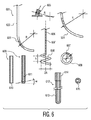
開示のシステム及び方法を実現し用いる際の通常の当業者を補助するために、添付図面を参照するものである。 To assist those of ordinary skill in the art in implementing and using the disclosed systems and methods, reference is made to the accompanying drawings.
本開示内容は、脳などの解剖学的領域に関連した目標組織領域に順応するための少なくとも部分的に湾曲したリードを利用するシステム及び方法を提供するものである。目標組織領域は、図2及び図5に示されるような神経性刺激、脳活動記録又は薬剤/化学物質搬送などの治療を受けることになっている。模範的実施例において、リードは、挿入軌道の或る特定の曲率が達成されるような挿入中の機械的横歪みの下で予め曲げられるか又は整形させられるようにすることが可能である。 The present disclosure provides systems and methods that utilize at least partially curved leads to accommodate a target tissue region associated with an anatomical region such as the brain. The target tissue region is to receive treatment such as neural stimulation, brain activity recording or drug / chemical delivery as shown in FIGS. In an exemplary embodiment, the lead can be pre-bent or shaped under mechanical lateral strain during insertion such that a certain curvature of the insertion trajectory is achieved.
図1は、典型的な患者100の頭蓋骨101を貫通する伝統的なほぼ直線状の移植可能型医療装置103を示している。深部脳刺激ユニット103は、目標の組織領域102に到達し及び/又はこれを刺激するようにされている。但し、ユニット103は、ほぼ直線的である(すなわち、湾曲がない)ので、目標組織領域102の一部分だけがユニット103により到達可能である。
FIG. 1 shows a traditional generally straight implantable
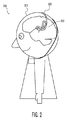
脳の目標組織領域の刺激について述べているが、限定はしないが目標組織活動(例えば脳活動)の記録及び薬剤/化学物質搬送を含む幾つもの他の治療のために挿入可能であることが分かる。図2は、図1に示されるような従来技術のシステムを凌ぐ特別な利点を示す本開示内容に関連した模範的実施例を示している。図2に示されるシステムに関連した特別な利点は、目標組織領域により規定される所期の幾何学的構造とより効果的に順応することができるように、限定はしないが、治療挿入ユニットに関連したリードを含む。図2は、典型的な患者200に関連した頭蓋骨201の中へ挿入される相当湾曲した脳刺激ユニット203を示している。湾曲ユニット203は、典型的な目標組織領域202と順応するよう適合させられる。
It describes stimulation of the target tissue area of the brain, but it can be seen that it can be inserted for a number of other treatments including but not limited to recording of target tissue activity (eg brain activity) and drug / chemical delivery. . FIG. 2 illustrates an exemplary embodiment associated with the present disclosure that exhibits particular advantages over the prior art system as shown in FIG. Special advantages associated with the system shown in FIG. 2 include, but are not limited to, the treatment insertion unit so that it can more effectively adapt to the intended geometry defined by the target tissue region. Includes related leads. FIG. 2 shows a substantially curved
模範的実施例において、本来備わっている比較的に小さい機械的歪みを有するリードは、図4,図6及び図7に示されるような湾曲した軌道に沿ってリードを配置することを容易にする挿入ツールとの組み合わせで用いることができる。挿入ツールを用いることによって、柔軟な脳組織の特性と比較的同様の機械的特性を有するかなりソフトで柔軟性のあるリードの配置及び/又は挿入が可能となる。目標組織領域に対して同様の機械的特性を有するリードは、長期移植状態の下では普通の、瘢痕組織進行又は他の生体適合性反応のような望ましくない脳組織反応を軽減する際に効果的なものとすることができる。模範的実施例において、組み合わせシステムは、比較的ソフトな柔軟性リードとの組み合わせで予め引っ張られた取り外し可能型(すなわち除去可能型)ガイドワイヤ(どちらもシリンジのような搬送ユニットを介して所望の箇所に搬送させられる)を用いることを含む。 In the exemplary embodiment, the inherently low lead mechanical strain facilitates placement of the lead along a curved track as shown in FIGS. 4, 6 and 7. It can be used in combination with an insertion tool. The use of an insertion tool allows for the placement and / or insertion of fairly soft and flexible leads having mechanical properties that are relatively similar to those of flexible brain tissue. Leads with similar mechanical properties to the target tissue area are effective in reducing undesirable brain tissue reactions, such as scar tissue progression or other biocompatible reactions, which are normal under long-term transplant conditions Can be. In an exemplary embodiment, the combination system is a removable (i.e., removable) guidewire that is pre-tensioned in combination with a relatively soft flexible lead (both desired via a delivery unit such as a syringe). To be transported to a location).
模範的実施例において、目標箇所の中へのリードの挿入は、挿入中に近位部分において機械的横歪みを誘発させることのできる挿入ツールにより案内される。以下の例は、本開示内容に関連した特定の模範的実施例を説明するものであり、そのような実施例に本開示内容の範囲を限定するものではない。むしろ、ここに提示される説明から当業者には容易に明らかになるように、本開示内容の主旨又は範囲から外れることなく変形、変更及び増強を含ませることができるものである。 In the exemplary embodiment, insertion of the lead into the target location is guided by an insertion tool that can induce mechanical lateral strain at the proximal portion during insertion. The following examples illustrate specific exemplary embodiments related to the present disclosure and are not intended to limit the scope of the present disclosure to such embodiments. Rather, modifications, changes and enhancements may be included without departing from the spirit or scope of the present disclosure, as will be readily apparent to those skilled in the art from the description provided herein.
模範的実施例において、硬い予め湾曲させられたリードは、患者の頭蓋骨を貫通し、目標の脳組織領域などの目標箇所に到達し順応するようになる。この予め湾曲させられたリードは、円形の少なくとも部分的な孤を規定するようサイズ決めされかつ整形される。部分的に湾曲した挿入ツール(例えばシリンジ)は、システム全体の機械的強度を増加させこれにより挿入精度を向上させるよう、有利な形態で、移植中にリードと係合するものである。 In an exemplary embodiment, a hard, pre-curved lead penetrates the patient's skull and reaches and adapts to a target location, such as a target brain tissue region. The pre-curved lead is sized and shaped to define at least a partial arc of a circle. A partially curved insertion tool (e.g., syringe) is one that advantageously engages the lead during implantation to increase the mechanical strength of the overall system and thereby improve insertion accuracy.
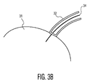
図3Aは、本開示内容に関連した模範的挿入システム30を示している。模範的システム30は、内部挿入リード34を支持しこれと係合した外部挿入ツール32を含む。挿入ツール32は、頭蓋骨のような典型的目標領域を少なくとも部分的に貫通するよう適合させられる。これは、頭蓋骨31により取り巻かれる脳の一部のような目標組織領域に対してリード34の精細かつ効果的な位置決めを見越すものである。図3A及び図3Bに示される挿入ツール32は、リード34の外部にあり、これにより、リード34の外表面を取り巻き又はこれに対して少なくとも位置づけられる。図3Bは、挿入ツール32が頭蓋骨31を貫通しないように外部挿入ツール32により取り巻かれるリード34を有する挿入システム30の模範的実施例を示している。
FIG. 3A illustrates an
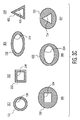
模範的実施例において、模範的挿入ツールは、リードに対して外部に又はリードに対して内部に位置づけられることができる。図3Cは、模範的な内部リードに対する挿入ツールの幾何学的関係を示す模範的外部挿入ツール断面を示している。断面図301,302,303及び304は、リード及び挿入ツールの双方が相似の幾何学的構造を規定するように模範的理リードを取り巻く外部挿入ツールの断面図を表している。したがって、図301は、模範的内部リード134及び模範的外部挿入ツール132の円形の幾何学的構造を表し、図302は、模範的内部リード234及び模範的外部挿入ツール232の四角い幾何学的構造を表し、図303は、模範的内部リード334及び模範的外部挿入ツール332の楕円形の幾何学的構造を表し、図304は、模範的内部リード434及び模範的外部挿入ツール432の三角形の幾何学的構造を表す。
In an exemplary embodiment, the exemplary insertion tool can be positioned external to the lead or internal to the lead. FIG. 3C shows an exemplary external insertion tool cross section showing the geometric relationship of the insertion tool to an exemplary internal lead.
挿入角度制御を向上させるため、模範的挿入ツール(例えばシリンジ)は、非回転対称な断面の幾何学的構造を規定するものが用いられる。模範的断面図305,306及び307に示されるように、模範的外部挿入ツールの断面により規定される幾何学的構造は、模範的内部リードの断面により規定される幾何学的構造とは異なるものとすることができる。断面図305は、模範的な四角形のリード534を取り巻く模範的円形の外部挿入ツール532を示す。図306は、模範的な楕円形のリード634を取り巻く模範的な円形の外部挿入ツール632を示している。図307は、模範的な三角形のリード734を取り巻く模範的な円形の外部挿入ツール732を示している。内部リードについて述べているが、前に説明した幾何学的構造の実施例は、リードに対して内部に位置づけられる挿入ツールに係合した外部リードなどの代替えの実施例に適している。
To improve insertion angle control, an exemplary insertion tool (eg, syringe) is used that defines a non-rotationally symmetric cross-sectional geometry. As shown in exemplary
模範的実施例において、本開示内容は、移植中に挿入ツールに一時的に係合されその後に取り外されることのできる比較的にソフトな柔軟性のあるリードとの組み合わせで円形の幾何学的構造の略弧状部を規定する予め湾曲された挿入ツールを含む脳刺激システムを提供するものである。模範的実施例において、この挿入ツールはガイドワイヤである。本開示内容に関連した模範的実施例では、閉じられた近位端部を有する管状リードと組み合わされるガイドワイヤは、配置及び/又は移植処理の間にガイドワイヤの固定化を可能とし、目標の箇所に届くとガイドワイヤの実際の取り外しを容易にする。挿入ツールは、移植処理の終了において取り外し可能である。模範的実施例においては、付加的な挿入ツールを、全体の構成の機械的強度を高めこれにより挿入精度を上げるために移植の間に用いることができる。 In an exemplary embodiment, the present disclosure provides a circular geometry in combination with a relatively soft flexible lead that can be temporarily engaged and subsequently removed from an insertion tool during implantation. The present invention provides a brain stimulation system including a pre-curved insertion tool that defines a substantially arcuate portion of the device. In the exemplary embodiment, the insertion tool is a guide wire. In an exemplary embodiment related to the present disclosure, a guidewire combined with a tubular lead having a closed proximal end allows for fixation of the guidewire during the placement and / or implantation process, When it reaches the location, it facilitates the actual removal of the guide wire. The insertion tool can be removed at the end of the implantation process. In an exemplary embodiment, additional insertion tools can be used during implantation to increase the mechanical strength of the overall configuration and thereby increase insertion accuracy.
図4Aないし図4Cにおいて説明され図示されるような柔軟リードを利用することに関連した特別な利点は、限定するものではないが、目標脳組織とほぼ同様の機械的特性を有しこれに伴い少なくとも或る一定の所望されない脳刺激及び/又は接触を回避するリードを含む。これにより、挿入及び/又は刺激プロセスの間において望まれない傷を生じる機会を大幅に減らすことができる。 The particular advantages associated with utilizing a flexible lead as described and illustrated in FIGS. 4A-4C include, but are not limited to, mechanical properties that are substantially similar to the target brain tissue and are associated therewith. Includes a lead that avoids at least certain undesired brain stimulation and / or contact. This can greatly reduce the chance of creating unwanted wounds during the insertion and / or stimulation process.
図4Aは、本開示内容に関連した模範的挿入システム40を示している。模範的システム40は、外部リード44に係合した内部挿入ツール42を含む。挿入ツール42は、軟性リード44を特定の目標箇所(例えば目標の脳組織領域)に案内するよう適合したガイドワイヤとすることができる。模範的実施例において、ガイドワイヤ42は、挿入中にリード44に対して除去可能に係合され、リード44が目標組織領域に順応するよう移植されると取り外されることが可能である。これにより、頭蓋骨41により取り巻かれる脳の一部分の如き目標組織領域に対してリード44の精確かつ効果的な位置決めが可能となる。
FIG. 4A illustrates an
図4Bは、本開示内容に関連した模範的挿入システム40´を示している。模範的システム40´は、リード44´に対し内部に位置づけられた第1の内部挿入ツール42´を含み、リード44´が頭蓋骨41内の目標脳組織領域のような目標箇所に届くようリード44´を案内するよう適合させられる。普通、第1の挿入ツール42´は、ガイドワイヤである。システム40´は、さらに、リード44´に対して内部に位置づけられ第1の挿入ツール42´を取り巻く第2の挿入ツール43を含む。模範的実施例において、リード44´は、閉じられた近位端を有するほぼ管状の幾何学的構造を規定する。第2の挿入ツール43は、第1の挿入ツール42´をほぼ取り囲む。
FIG. 4B illustrates an exemplary insertion system 40 'associated with the present disclosure. The
図4Cは、第1の挿入ツールを取り巻く第2の挿入ツールの幾何学的関係性を示した第1及び第2の挿入ツールの模範的な断面図を示している。断面図401,402及び403は、模範的第1の挿入ツールを取り巻く第2の外部挿入ツールの断面図を表している。模範的な図401は、模範的な第1の内部挿入ツール142と、模範的な取り巻きの第2の挿入ツール143とを示しており、どちらの挿入ツールも、ほぼ円形の幾何学的構造を規定するようなものとなっている。挿入角制御を改善するため、模範的挿入ツール(例えばシリンジ)は、非回転対称断面の幾何学的構造を規定するものが用いられる。模範的断面図402及び403に示されるように、模範的な内部の第1の挿入ツールの断面により規定される幾何学的構造は、模範的な取り巻きの第2の内部の挿入ツールの断面により規定される幾何学的構造とは異なるものとすることができる。断面図402は、模範的な四角い第1の挿入ツール242を取り巻く模範的な円形の第2の内部挿入ツール243を示している。図403は、模範的な三角形の第1の挿入ツール342を取り巻く模範的な円形の第2の内部挿入ツール343を示している。
FIG. 4C shows an exemplary cross-sectional view of the first and second insertion tools showing the geometric relationship of the second insertion tool surrounding the first insertion tool.
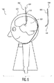
模範的実施例において、本開示内容に関連した刺激システムは、硬いが柔軟性のある機械的特性を有するように作られたリードを含む。このリードは、直線状部分と円形部の孤状部分とを有する形で事前に湾曲させられることが可能であり、この事前湾曲可能な点に加え、或いはこれに代わり湾曲させられることができる。図5は、リード554を含む模範的な刺激システム550を示す。図5に示されるように、システム550は、脳502に関連した目標組織領域に届くように模範的患者500に関連した頭蓋骨501を貫通している。リード554は、挿入ツール552により取り巻かれる。リード554は、直線状部555及び湾曲部556を含む。
In an exemplary embodiment, a stimulation system related to the present disclosure includes a lead made to have a hard but flexible mechanical property. The lead can be pre-curved with a straight portion and a circular arcuate portion, and can be curved in addition to or instead of the pre-curvable point. FIG. 5 shows an
湾曲部556は、目標組織領域の効果的治療(例えば刺激印加)のために目標組織領域に順応するとともに、脳502に関連した非目標組織領域の刺激及び破壊を回避するように適合される。模範的実施例において、挿入は、直線状のシリンジ様挿入ツール552により行われる。模範的実施例において、シリンジ552は、リード554のかなり湾曲した部分556を真っ直ぐにするとともに、リード554は、挿入の間、シリンジ552に対して内部に位置づけられる。さらにこれにより、リード554は、シリンジ552の近位端部を出た後に湾曲した軌道に従うことができる。
The
図5に示されるような円形及び/又は螺旋形の孤の幾何学的構造の実施例を用いることについての特別な利点は、挿入経路に近接した組織に対して生じうる脳組織損傷を制限することを含む。このリードは、挿入経路に沿って動くリード先端を含む。円形及び/又は螺旋の孤の実施例において、リードの全ての部分は、挿入中に当該リード先端と同じ経路に従う。付加的な利点は、目標組織領域の幾何学的構造に対して順応するためのより解剖学的な方向付け可能なリードの利点を得るよう当該軌道の最終的部分を除き、解剖学的目標領域に対する略線状及び/又は直線的挿入接近の伝統的な標準をサポートすることを含む。 The particular advantage of using the circular and / or helical arcuate geometry embodiment as shown in FIG. 5 limits brain tissue damage that can occur to tissue proximate the insertion path. Including that. The lead includes a lead tip that moves along the insertion path. In circular and / or spiral arc embodiments, all portions of the lead follow the same path as the lead tip during insertion. An additional advantage is that, except for the final part of the trajectory to obtain the advantage of a more anatomically orientable lead to adapt to the geometry of the target tissue region, the anatomical target region Support for traditional standards of approximate linear and / or linear insertion approach to
模範的実施例において、図5に示されるように挿入処理に関連した脳組織損傷を制限することは、最小の残留歪みが挿入ツールの近位端において規定された出口開口部に存在するようにデザインされた近位端を有する挿入ツールを提供することにより達成される。模範的実施例において、これは、シリンジの出口チャネルをリード(湾曲部)の延長部分の所望の軌道に位置合わせすることによって達成される。模範的実施例において、出口チャネルは、リードの事前湾曲部と同じ半径を有する部分的に湾曲した部分を含む。普通、出口チャネル長及び直径は、リードの延在部の残留歪みが最小化されるようサイズ決めされ整形されるのが良い。模範的実施例において、挿入ツールは、移植処理の終わりにおいて除去されるように構成される。図3C及び図4Cを参照して説明した実施例と同様に、当該挿入角における制御を改善するため、非回転対称断面(例えば四角、楕円又は三角形)を有する挿入ツールを使うことができる。 In an exemplary embodiment, limiting brain tissue damage associated with the insertion process as shown in FIG. 5 is such that a minimal residual strain exists at the exit opening defined at the proximal end of the insertion tool. This is accomplished by providing an insertion tool having a designed proximal end. In the exemplary embodiment, this is accomplished by aligning the exit channel of the syringe with the desired trajectory of the lead extension. In the exemplary embodiment, the exit channel includes a partially curved portion having the same radius as the pre-curved portion of the lead. Typically, the exit channel length and diameter should be sized and shaped to minimize residual strain in the lead extension. In an exemplary embodiment, the insertion tool is configured to be removed at the end of the implantation process. Similar to the embodiment described with reference to FIGS. 3C and 4C, an insertion tool having a non-rotationally symmetric cross-section (eg, square, ellipse or triangle) can be used to improve control over the insertion angle.
リードを、図5に示されるようにリードの部分的に湾曲した部分に由来する目標組織領域の幾何学的構造と順応させることは、目標領域を刺激するために必要以上に長くない軌道を見越すものである。さらに、挿入軌道の計画に関する難しさは、当該軌道の殆どがほぼ直線的であるので、軽減される。硬いリードを用いる場合、(柔らかい)脳組織に関連した機械的特性は、リードのものと同様に合致せず、これにより、慢性使用又は挿入の間、局部的な脳損傷又は悪い組織応答のリスクを増加させる可能性がある。 Accommodating the lead with the geometric structure of the target tissue region derived from the partially curved portion of the lead as shown in FIG. 5 allows for a trajectory that is not longer than necessary to stimulate the target region. Is. Furthermore, the difficulty associated with planning the insertion trajectory is mitigated because most of the trajectory is approximately linear. When using a hard lead, the mechanical properties associated with (soft) brain tissue do not match as well as that of the lead, which results in the risk of local brain damage or poor tissue response during chronic use or insertion. May increase.
本開示内容は、移植中にガイドワイヤに対して一時的に係合させられその後に取り外されることの可能なソフトな柔軟性のあるリードとの組み合わせで直線状部分と湾曲部とを有する硬いが柔軟性のある予め湾曲させられた第1の挿入ツール(例えばガイドワイヤ)を含むシステムを提供するものである。上記例3についての実施例と同様に、ガイドワイヤの湾曲した部分を真っ直ぐにするとともに挿入中はシリンジの内部にあるものとし、リードに対して係合させられるガイドワイヤをシリンジの近位端を出た後に湾曲した軌道に従わせることを可能にする付加的な直線状のシリンジ様の第2の挿入ツールによって挿入を行うことができる。模範的実施例において、第1の挿入ツール(例えばガイドワイヤ)及び付加的な第2の挿入ツール(例えばシリンジ又はカニューレ)は、リードに対して外部か又は内部に位置づけることができる。 The present disclosure provides a stiff but straight portion and a curved portion in combination with a soft flexible lead that can be temporarily engaged with a guidewire during implantation and subsequently removed. A system is provided that includes a flexible pre-curved first insertion tool (eg, a guide wire). Similar to the example for Example 3 above, the curved portion of the guidewire should be straightened and inside the syringe during insertion, and the guidewire engaged with the lead should be Insertion can be performed by an additional linear syringe-like second insertion tool that allows it to follow a curved trajectory after exiting. In an exemplary embodiment, a first insertion tool (eg, a guide wire) and an additional second insertion tool (eg, a syringe or cannula) can be positioned externally or internally to the lead.
模範的実施例において、図5に示されるように挿入処理に関する脳組織損傷を制限することは、挿入ツールの近位端に規定された出口開口部に最小の残留歪みが存在するようにデザインされた近位端を有する挿入ツールを提供することによって達成可能である。模範的実施例において、これは、シリンジの出口チャネルをガイドワイヤ(湾曲部)の所望の軌道に位置合わせすることによって達成される。模範的実施例において、出口チャネルは、ガイドワイヤの予め湾曲した部分と同じ半径を有する部分的に湾曲した部分を含む。普通、出口チャネルの長さ及び直径は、リードの延長部分の残留歪みが最小化されるようにサイズ設定され整形されるのが良い。模範的実施例において、挿入ツール(例えば、シリンジ及びガイドワイヤ)は、移植処理の終わりに除去されるように適合される。図3C及び図4Cを参照して説明される実施例と同様に、挿入角について制御を改善するため、非回転対称な断面(例えば、四角形、長円形又は三角形)を有する挿入ツールを使うことができる。 In an exemplary embodiment, limiting brain tissue damage related to the insertion process as shown in FIG. 5 is designed such that there is minimal residual strain at the exit opening defined at the proximal end of the insertion tool. This can be achieved by providing an insertion tool having a proximal end. In the exemplary embodiment, this is accomplished by aligning the exit channel of the syringe with the desired trajectory of the guide wire (bend). In the exemplary embodiment, the exit channel includes a partially curved portion having the same radius as the pre-curved portion of the guidewire. In general, the length and diameter of the exit channel should be sized and shaped so that residual strain in the lead extension is minimized. In an exemplary embodiment, the insertion tool (eg, syringe and guide wire) is adapted to be removed at the end of the implantation process. Similar to the embodiment described with reference to FIGS. 3C and 4C, an insertion tool having a non-rotationally symmetric cross-section (eg, square, oval or triangular) may be used to improve control over the insertion angle. it can.
模範的実施例において、本開示内容に関連した刺激システムは、リードが図8に示したような略螺旋形状(すなわち、コルク抜き形状)を規定する点を除き、上記例1について説明したようなものと同様のリードを含む。図8は、脳802を閉じる頭蓋骨801を有する典型的患者800を示す。コルク抜き形状のリード884は、模範的な脳802に関連した目標組織領域に達しこれに順応するよう頭蓋骨801を貫通する。模範的実施例において、例1のように、リードは硬く予め湾曲させられている。例1及び例5に関連する特別の利点は、大きな直径の生理学的目標の場合、刺激ボリュームに関連した目標組織領域に対する順応が改善される点である。
In an exemplary embodiment, the stimulation system associated with the present disclosure is as described for Example 1 above, except that the lead defines a generally helical shape (ie, a corkscrew shape) as shown in FIG. Includes leads similar to those. FIG. 8 shows a
模範的実施例において、本開示内容に関連した挿入システムは、ガイドワイヤが略螺旋形状(すなわち、コルク抜き形状)を規定する点を除き、上記例5について説明したようなガイドワイヤと同様のガイドワイヤを含む。このガイドワイヤは、硬く予め湾曲させられたガイドワイヤであり、移植中にガイドワイヤに対して一時的に係合させられその後に取り外されることのできるソフトな柔軟性のあるリードとの組み合わせで利用可能なものである。 In an exemplary embodiment, the insertion system associated with the present disclosure is a guide similar to the guide wire as described for Example 5 above, except that the guide wire defines a generally helical shape (ie, a corkscrew shape). Includes wires. This guidewire is a hard, pre-curved guidewire that is used in combination with a soft, flexible lead that can be temporarily engaged with the guidewire during implantation and then removed. It is possible.
模範的実施例において、本開示内容に関連した刺激システムは、リードが図9に示されるように直線状部分と螺旋(すなわちコルク抜き形状)部分とを有する硬い予め湾曲させられたリードである点を除き、上記例3について説明したようなリードと同様のリードを含む。図9は、脳902を取り囲む頭蓋骨901を有する典型的患者900を示す。模範的リード994は、脳902に関連した目標組織領域に届きかつ順応するように頭蓋骨901を貫通する。リード994は、リード994を目標組織領域に案内するために挿入ツール992に対して一時的に係合させられる。リード994は、直線状の(すなわち、ほぼ線状の)部分995と螺旋状(すなわちコルク抜き形状)の部分996とを含む。
In an exemplary embodiment, the stimulation system associated with the present disclosure is that the lead is a rigid pre-curved lead having a straight portion and a helical (ie, corkscrew-shaped) portion as shown in FIG. Except for the lead as described in Example 3 above. FIG. 9 shows a
例3を参照して説明した実施例と同様に、リード994の挿入は、リードのコルク抜き形状の部分を真っ直ぐにする一方で、挿入中はシリンジ内部にありリードが当該シリンジの近位端を出た後に湾曲状すなわちコルク抜き状軌道に従うようにすることを可能にする直線状シリンジ様挿入ツールを用いて達成することができる。脳組織損傷の制限をなすため、挿入ツールの近位端は、リードの延在部分において最小の残留歪みが存在するようにデザインされるのが良い。シリンジの出口チャネルをリードの延在部の所望の軌道に位置合わせすることは、歪みの最小化を可能にする。
Similar to the embodiment described with reference to Example 3, insertion of the
図6を参照すると、模範的リード606は、直線状部607と螺旋状部608とを含む。模範的実施例において、螺旋状部分608は、2Rの直径を規定する円の湾曲部を作る。この湾曲部は、直線状部分607の延在突出部が608の螺旋状部分の外周に実質的に位置合わせされるように規定される。したがって、直線状部分607の延在突出部は、螺旋状部分608の中心軸と位置が合わない。608の周囲エッジに沿った607の関係を示す上面図は、図6において示される。
With reference to FIG. 6, an
模範的実施例において、本開示内容に関する挿入システムは、システムが、移植中にガイドワイヤに対して一時的に係合させられその後に取り外されることのできるソフトな柔軟性リードとの組み合わせで、直線状部分及び螺旋状(すなわち、コルク抜き形状)部分を有する硬い予め湾曲させられたガイドワイヤを含むことを除き、上記例7について説明したようなリードと同様のリードを含む。図5において前述したように、硬い予め湾曲させられたガイドワイヤは、移植中にガイドワイヤに対して一時的に係合させられその後に取り外されることのできるソフトなな柔軟性リードとの組み合わせで利用可能である。 In an exemplary embodiment, the insertion system according to the present disclosure is a straight line in combination with a soft flexible lead that can be temporarily engaged and subsequently removed from the guidewire during implantation. Includes a lead similar to that described for Example 7 above, except that it includes a hard, pre-curved guidewire having a shaped portion and a helical (ie, corkscrew shaped) portion. As previously described in FIG. 5, the hard pre-curved guidewire is combined with a soft flexible lead that can be temporarily engaged with the guidewire during implantation and subsequently removed. Is available.
模範的実施例において、本開示内容に関連した挿入システムは、当該リードが、挿入中に少なくともその近位部分において機械的横歪みを(制御された態様で)一時的に誘発させその後に挿入ツールからの解放により当該歪みを解放する手段を有する予め湾曲させられていない相当にソフトで柔軟性のあるリードである点を除き、上記例1,3,5及び7について説明したようなリードと同様のリードを含むものである。この実施例に関する特別な利点は、直線状の挿入ツール(例えばシリンジ)を通じた湾曲したリード(又はリードの湾曲した部分)を通過しつつ、挿入力制御を改善することである。 In an exemplary embodiment, an insertion system related to the present disclosure is such that the lead temporarily induces mechanical lateral strain (in a controlled manner) at least in its proximal portion during insertion, after which the insertion tool Similar to the leads as described for Examples 1, 3, 5 and 7 above, except that they are fairly soft and flexible leads that are not pre-curved and have means to release the distortion by releasing from Including the lead. A particular advantage with this embodiment is improved insertion force control while passing through a curved lead (or curved portion of the lead) through a linear insertion tool (eg, a syringe).
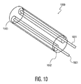
模範的実施例において、本開示内容に関連した挿入システムは、当該機械的横歪みが、遠位端から近位端への長手方向においてリードを通じて走る多数のワイヤにより発生する点を除き、上記例9について説明したようなものと同様のリードを含むものである。図10は、本開示内容に関する模範的な柔軟性リード1000を示しており、当該リードは、遠位端1003から近位端1002への長手方向においてリードを通じて走る複数のワイヤ1001を含む。ワイヤ1001は、機械的な横歪みを誘発させるよう適合させられる。
In an exemplary embodiment, the insertion system associated with the present disclosure is similar to the above example except that the mechanical lateral strain is generated by a number of wires running through the lead in the longitudinal direction from the distal end to the proximal end. This includes leads similar to those described for 9. FIG. 10 illustrates an exemplary
模範的実施例において、本開示内容に関する刺激印加システムは、システムが、挿入中に少なくともその近位部分において機械的横歪みを(制御された方法で)一時的に誘発させる手段を有する予め湾曲されていない柔軟性ガイドワイヤを含むことを除き、上記例2,4,6及び8について説明したようなガイドワイヤと同様のガイドワイヤを含むものである。この実施例に関する特別の利点は、直線状挿入ツール(すなわちシリンジ)を通じて湾曲したリード(又はリードの湾曲部分)を通過させながら、挿入力制御が改善されることを含む。 In an exemplary embodiment, a stimulation application system according to the present disclosure is pre-curved with means for causing the system to temporarily induce mechanical lateral strain (in a controlled manner) at least at its proximal portion during insertion. It includes a guide wire similar to the guide wire as described for Examples 2, 4, 6 and 8 above, except that it does not include a flexible guide wire. Special advantages associated with this embodiment include improved insertion force control while passing a curved lead (or curved portion of the lead) through a linear insertion tool (ie, syringe).
模範的実施例において、本開示内容に関する挿入システムは、機械的横歪みが、遠位端から近位端への長手方向においてガイドワイヤを通じて走る多数のワイヤにより例10と同様に発生されることを除き、上記例11について説明したようなリードと同様のリードを含むものである。 In an exemplary embodiment, the insertion system according to the present disclosure provides that mechanical lateral strain is generated as in Example 10 with multiple wires running through the guidewire in the longitudinal direction from the distal end to the proximal end. Except for the above, the same lead as described in Example 11 is included.
図6及び図7を参照して、例1ないし例12を参照して説明したような本開示内容に関するシステムの模範的実施例の特定の構成部をより詳しく説明する。図6は、解剖学的目標又は目標組織領域に対して遠位のほぼ直線状の部分602と、解剖学的目標に近接した曲率半径Rを規定する湾曲部603とを有する模範的な最も内側のガイドワイヤ601を示す。他の模範的実施例において、最も内側のガイドワイヤは、模範的な湾曲ガイドワイヤ604により示されるように全体的に湾曲させられたもの(すなわち、円形湾曲の孤)とすることができる。全部が湾曲したガイドワイヤ604を用いた模範的システムは、さらに、ガイドワイヤのものと等しい半径Rを規定する同様に湾曲した内側部分を規定する挿入片605を含む。
With reference to FIGS. 6 and 7, certain components of an exemplary embodiment of a system according to the present disclosure as described with reference to Examples 1-12 will be described in more detail. FIG. 6 shows an exemplary innermost portion having a generally
他の模範的実施例において、最も内側のガイドワイヤ606は、本開示内容に関する模範的システムに含まれる。ガイドワイヤ606は、解剖学的目標(すなわち、目標組織領域)に対して遠位のほぼ直線状の部分607と、解剖学的目標に近接した螺旋曲率R及び螺旋ピッチhを規定する螺旋部分608と、を含む。機械的デザイン及び応力分布目標のため、直線状部607は、螺旋部分608の螺旋軸に平行とされ、螺旋部分608を含む円筒状表面に含まれるものとするのが良い。
In other exemplary embodiments, the
再度図6を参照すると、模範的実施例において、この挿入システムは、軸開口610を持つ真っ直ぐな管体を含む最も外側のガイド管609を含むようにしてもよい。ガイド管609は、タイプ601又は604のガイドワイヤに対して適している。他の実施例において、最も外側のガイド管609は、横方向の開口部611を持つ直線状管体である。開口部611を持つ管体609を含む実施例は、螺旋の挿入タイプ606と連携して用いるのに効果的である。普通、開口部611の内壁の勾配は、図6に示されるように角度アルファを規定する。角度アルファは、普通、h及び2Rが模範的螺旋部分608の螺旋の角度に関連づけられるように、(h/2R)のアークタンジェントにより規定される角度に等しい。模範的実施例において、開口部611は、螺旋部分608の角部曲率に等しい出口角度アルファだけ傾斜している。
Referring again to FIG. 6, in an exemplary embodiment, the insertion system may include an
模範的実施例において、リード612は、オプションとして、主たる柔軟性ボディ613及びヘッド614からなるものとすることができる。通常、ボディ613及びヘッド614の内側断面615は、解剖学的目標(例えば、目標組織領域)に対して当該ガイドワイヤ及び/又はガイド管を方向づけるように適合させられる。
In the exemplary embodiment, the
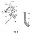
図7は、模範的挿入アーキテクチャを示している。模範的実施例において、本開示内容に関するシステムは、頭蓋骨704に対して挿入システムを位置づけることを可能にする位置決め装置を含む。位置決め装置は、現行の機器とほぼ一致するものとすることができ、限定はしないが、立体画フレームの案内ツール又はこれに等価なツールを含む。模範的位置決め装置は、位置決め装置703として図7に概略的描かれている。装置703は、模範的な解剖学的目標706に届くようほぼ真っ直ぐな軌道702に沿って模範的リード612の挿入が可能なように適合させられている。模範的実施例において、リード612は、ほぼ湾曲した軌道705に沿って目標領域706に届きこれに順応するように案内される。
FIG. 7 illustrates an exemplary insertion architecture. In an exemplary embodiment, a system related to the present disclosure includes a positioning device that allows positioning of the insertion system relative to the
模範的実施例において、基本的に、挿入は次のようにして行われる。最も外側のガイド管体609(第2の挿入ツール)がリード612内に挿入される。最初に進入する先端を有する最も内側のガイドワイヤ601(第1の挿入ツール)は、当該先端が開口部(図6に示されるような610又は611)に届くまで最も外側のガイド管609の中に挿入される。ガイドワイヤ609は、ガイド管609内に全部留まる。ガイド管609は、管体609の一部が目標組織領域706に位置するポイント701に届くように当該リードに対して近接するまで動作させられる。ポイント701に届くと、リード612の湾曲した軌道は、始動させられる。当該湾曲した軌道の誘導部分の間に、ガイド管609が固定される。湾曲した軌道は、ガイドワイヤ601の予め湾曲させられて整形された部分が開口部610/611から出るようにしてガイド管609を通るようガイドワイヤ601をスライドさせ、これにより、所期の経路705に沿って湾曲部分又は螺旋部を始動させることによって実現される。リード612の先端は、所期の位置に届いたとき、このリードの位置が維持されるとともに、当該内部のガイドワイヤはガイド管の中へ後退させられる。ガイド管及びガイドワイヤは、その後に引き込ませられる。
In the exemplary embodiment, the insertion is basically performed as follows. The outermost guide tube 609 (second insertion tool) is inserted into the
模範的実施例において、リードは、少なくとも1つの電極を含む。この電極は、金属物質から構成可能であり、或いは金属被覆を含む。被覆は、リード及び組織の界面において少なくとも保護の効果を奏する連続的、均質性、異質性又は構造化された材料としなければならない。 In an exemplary embodiment, the lead includes at least one electrode. The electrode can be composed of a metallic material or includes a metal coating. The coating should be a continuous, homogeneous, heterogeneous or structured material that at least provides a protective effect at the lead and tissue interface.
以上、本開示内容を、模範的実施例及びその実現形態について説明したが、開示したシステム及び方法は、このような模範的実施例/実現形態に限定されるものではない。むしろ、ここに提示した説明から当業者が容易に分かることになるように、開示したシステム及び方法は、本開示内容の主旨又は範囲から外れることなく変形、変更及び増強をすることは可能である。したがって、ここで提示した開示内容は、その範囲内におけるこのような変形、変更及び増強を明確に含むものである。 Although the present disclosure has been described with respect to exemplary embodiments and implementations thereof, the disclosed systems and methods are not limited to such exemplary embodiments / implementations. Rather, as will be readily appreciated by those skilled in the art from the description provided herein, the disclosed systems and methods may be modified, changed and enhanced without departing from the spirit or scope of the present disclosure. . Accordingly, the disclosure presented herein specifically includes such modifications, changes, and enhancements within its scope.
Claims (39)
(b)前記リードに除去可能に係合した少なくとも第1の挿入ツールと、
を有する目標組織挿入システムであって、
前記目標組織領域は、解剖学的構造を規定し、前記リードは、前記目標組織領域の解剖学的構造に順応するよう適合させられた湾曲部を規定し、
前記挿入ツールは、前記目標組織領域に係合するよう前記目標の解剖学的構造の中へ前記リードを挿入するよう適合させられ、
前記挿入ツールは、前記リードが前記目標組織領域に対して位置づけられると除去可能である、
システム。 (A) a lead adapted to access a target tissue region associated with the target anatomy;
(B) at least a first insertion tool removably engaged with the lead;
A target tissue insertion system comprising:
The target tissue region defines an anatomy, and the lead defines a bend adapted to conform to the anatomy of the target tissue region;
The insertion tool is adapted to insert the lead into the target anatomy to engage the target tissue region;
The insertion tool is removable when the lead is positioned relative to the target tissue region;
system.
(a)既に湾曲したリードを用意し、又は未だ湾曲していないリードに湾曲した軌道を誘発させるステップと、
(b)前記リードに対して少なくとも第1の挿入ツールを除去可能に係合させるステップと、
(c)前記目標組織領域に到達するよう目標の解剖学的構造を通じて前記リード及び当該係合された挿入ツールを挿入するステップと、
を有し、
前記リードは、前記目標組織領域の幾何学的構造に順応するように湾曲させられ、
前記少なくとも第1の挿入ツールは、前記リードに対して内部又は外部に位置づけられることが可能であり、
前記リードは、前記目標組織領域の刺激印加、前記目標組織領域に関する活動の記録及び前記目標組織領域への薬剤及び/又は化学物質の搬送からなるグループから選択される機能を行うよう適合させられ、
前記少なくとも第1の挿入ツールは、前記リードを前記目標組織領域に届かせるように案内する、
方法。 A method for inserting a lead into a target tissue region to accommodate the geometric structure of the target tissue region, comprising:
(A) providing an already curved lead or inducing a curved trajectory in a lead that is not yet curved;
(B) removably engaging at least a first insertion tool with the lead;
(C) inserting the lead and the engaged insertion tool through a target anatomy to reach the target tissue region;
Have
The lead is curved to conform to the geometric structure of the target tissue region;
The at least first insertion tool can be positioned internal or external to the lead;
The lead is adapted to perform a function selected from the group consisting of applying a stimulus to the target tissue region, recording an activity related to the target tissue region, and delivering a drug and / or chemical to the target tissue region;
The at least first insertion tool guides the lead to reach the target tissue region;
Method.
Applications Claiming Priority (3)
| Application Number | Priority Date | Filing Date | Title |
|---|---|---|---|
| US94174007P | 2007-06-04 | 2007-06-04 | |
| US60/941,740 | 2007-06-04 | ||
| PCT/IB2008/052163 WO2008149289A2 (en) | 2007-06-04 | 2008-06-03 | Insertion system and lead for treatment of a target tissue region |
Publications (2)
| Publication Number | Publication Date |
|---|---|
| JP2011517575A true JP2011517575A (en) | 2011-06-16 |
| JP2011517575A5 JP2011517575A5 (en) | 2011-09-01 |
Family
ID=39735028
Family Applications (1)
| Application Number | Title | Priority Date | Filing Date |
|---|---|---|---|
| JP2010510934A Pending JP2011517575A (en) | 2007-06-04 | 2008-06-03 | Insertion system and lead for treatment of target tissue region |
Country Status (6)
| Country | Link |
|---|---|
| US (1) | US20100152747A1 (en) |
| EP (1) | EP2155322A2 (en) |
| JP (1) | JP2011517575A (en) |
| CN (1) | CN101678204A (en) |
| DE (1) | DE202008018476U1 (en) |
| WO (1) | WO2008149289A2 (en) |
Cited By (2)
| Publication number | Priority date | Publication date | Assignee | Title |
|---|---|---|---|---|
| JP2014512847A (en) * | 2010-11-30 | 2014-05-29 | フューグリスタ,ファビアン,ヘルマン,ウルバン | Helical insert |
| JPWO2016021633A1 (en) * | 2014-08-05 | 2017-08-03 | 国立大学法人 東京医科歯科大学 | Biomagnetic measurement device |
Families Citing this family (46)
| Publication number | Priority date | Publication date | Assignee | Title |
|---|---|---|---|---|
| US9205261B2 (en) | 2004-09-08 | 2015-12-08 | The Board Of Trustees Of The Leland Stanford Junior University | Neurostimulation methods and systems |
| US20120277839A1 (en) | 2004-09-08 | 2012-11-01 | Kramer Jeffery M | Selective stimulation to modulate the sympathetic nervous system |
| US9427570B2 (en) | 2006-12-06 | 2016-08-30 | St. Jude Medical Luxembourg Holdings SMI S.A.R.L. (“SJM LUX SMI”) | Expandable stimulation leads and methods of use |
| AU2007329253B2 (en) | 2006-12-06 | 2014-03-27 | Spinal Modulation, Inc. | Delivery devices, systems and methods for stimulating nerve tissue on multiple spinal levels |
| WO2008070809A2 (en) | 2006-12-06 | 2008-06-12 | Spinal Modulation, Inc. | Implantable flexible circuit leads and methods of use |
| AU2008210504B2 (en) | 2007-01-29 | 2012-07-26 | Spinal Modulation, Inc. | Sutureless lead retention features |
| JP5653918B2 (en) | 2008-07-30 | 2015-01-14 | エコーレ ポリテクニーク フェデラーレ デ ローザンヌ (イーピーエフエル) | Apparatus and method for optimized stimulation of neural targets |
| CA2739431C (en) | 2008-10-01 | 2016-12-06 | Sherwin Hua | System and method for wire-guided pedicle screw stabilization of spinal vertebrae |
| EP2373378B1 (en) | 2008-10-27 | 2017-04-26 | Spinal Modulation Inc. | Selective stimulation systems and signal parameters for medical conditions |
| EP3563902B1 (en) | 2008-11-12 | 2021-07-14 | Ecole Polytechnique Fédérale de Lausanne | Microfabricated neurostimulation device |
| AU2010229985B2 (en) | 2009-03-24 | 2015-09-17 | Spinal Modulation, Inc. | Pain management with stimulation subthreshold to paresthesia |
| US9259569B2 (en) | 2009-05-15 | 2016-02-16 | Daniel M. Brounstein | Methods, systems and devices for neuromodulating spinal anatomy |
| US9327110B2 (en) | 2009-10-27 | 2016-05-03 | St. Jude Medical Luxembourg Holdings SMI S.A.R.L. (“SJM LUX SMI”) | Devices, systems and methods for the targeted treatment of movement disorders |
| CA3026948C (en) | 2009-12-01 | 2022-07-12 | Ecole Polytechnique Federale De Lausanne | Microfabricated neurostimulation device and methods of making and using the same |
| CA2795159C (en) | 2010-04-01 | 2020-11-03 | Ecole Polytechnique Federale De Lausanne | Device for interacting with neurological tissue and methods of making and using the same |
| WO2011143233A2 (en) | 2010-05-10 | 2011-11-17 | Spinal Modulation, Inc. | Methods, systems and devices for reducing migration |
| US9919146B2 (en) | 2013-05-01 | 2018-03-20 | Sherwin Hua | Methods and systems for intraventricular brain stimulation |
| US10532203B2 (en) | 2013-05-06 | 2020-01-14 | Medtronic, Inc. | Substernal electrical stimulation system |
| US9220913B2 (en) | 2013-05-06 | 2015-12-29 | Medtronics, Inc. | Multi-mode implantable medical device |
| US9717923B2 (en) | 2013-05-06 | 2017-08-01 | Medtronic, Inc. | Implantable medical device system having implantable cardioverter-defibrillator (ICD) system and substernal leadless pacing device |
| US20140330287A1 (en) | 2013-05-06 | 2014-11-06 | Medtronic, Inc. | Devices and techniques for anchoring an implantable medical device |
| US10471267B2 (en) | 2013-05-06 | 2019-11-12 | Medtronic, Inc. | Implantable cardioverter-defibrillator (ICD) system including substernal lead |
| US9717898B2 (en) | 2013-05-06 | 2017-08-01 | Medtronic, Inc. | Systems and methods for implanting a medical electrical lead |
| US10556117B2 (en) | 2013-05-06 | 2020-02-11 | Medtronic, Inc. | Implantable cardioverter-defibrillator (ICD) system including substernal pacing lead |
| US10434307B2 (en) | 2013-10-15 | 2019-10-08 | Medtronic, Inc. | Methods and devices for subcutaneous lead implantation |
| US9610436B2 (en) | 2013-11-12 | 2017-04-04 | Medtronic, Inc. | Implant tools with attachment feature and multi-positional sheath and implant techniques utilizing such tools |
| US10792490B2 (en) * | 2013-11-12 | 2020-10-06 | Medtronic, Inc. | Open channel implant tools and implant techniques utilizing such tools |
| US10966620B2 (en) | 2014-05-16 | 2021-04-06 | Aleva Neurotherapeutics Sa | Device for interacting with neurological tissue and methods of making and using the same |
| US11311718B2 (en) | 2014-05-16 | 2022-04-26 | Aleva Neurotherapeutics Sa | Device for interacting with neurological tissue and methods of making and using the same |
| US9474894B2 (en) | 2014-08-27 | 2016-10-25 | Aleva Neurotherapeutics | Deep brain stimulation lead |
| US9403011B2 (en) | 2014-08-27 | 2016-08-02 | Aleva Neurotherapeutics | Leadless neurostimulator |
| US10328268B2 (en) | 2014-09-04 | 2019-06-25 | AtaCor Medical, Inc. | Cardiac pacing |
| US9636505B2 (en) | 2014-11-24 | 2017-05-02 | AtaCor Medical, Inc. | Cardiac pacing sensing and control |
| US10743960B2 (en) | 2014-09-04 | 2020-08-18 | AtaCor Medical, Inc. | Cardiac arrhythmia treatment devices and delivery |
| WO2016037144A2 (en) | 2014-09-04 | 2016-03-10 | AtaCor Medical, Inc. | Cardiac pacing lead delivery system |
| US9636512B2 (en) | 2014-11-05 | 2017-05-02 | Medtronic, Inc. | Implantable cardioverter-defibrillator (ICD) system having multiple common polarity extravascular defibrillation electrodes |
| US11097109B2 (en) | 2014-11-24 | 2021-08-24 | AtaCor Medical, Inc. | Cardiac pacing sensing and control |
| US11083491B2 (en) | 2014-12-09 | 2021-08-10 | Medtronic, Inc. | Extravascular implant tools utilizing a bore-in mechanism and implant techniques using such tools |
| US10349978B2 (en) | 2014-12-18 | 2019-07-16 | Medtronic, Inc. | Open channel implant tool with additional lumen and implant techniques utilizing such tools |
| US10729456B2 (en) | 2014-12-18 | 2020-08-04 | Medtronic, Inc. | Systems and methods for deploying an implantable medical electrical lead |
| US10223311B2 (en) * | 2015-03-30 | 2019-03-05 | Samsung Electronics Co., Ltd. | Semiconductor memory device for sharing inter-memory command and information, memory system including the same and method of operating the memory system |
| WO2017134587A1 (en) | 2016-02-02 | 2017-08-10 | Aleva Neurotherapeutics, Sa | Treatment of autoimmune diseases with deep brain stimulation |
| US10702692B2 (en) | 2018-03-02 | 2020-07-07 | Aleva Neurotherapeutics | Neurostimulation device |
| EP3976167A1 (en) | 2019-05-29 | 2022-04-06 | Atacor Medical, Inc. | Implantable electrical leads and associated delivery systems |
| US11666771B2 (en) | 2020-05-29 | 2023-06-06 | AtaCor Medical, Inc. | Implantable electrical leads and associated delivery systems |
| CN114847955B (en) * | 2022-07-05 | 2022-10-11 | 诺尔医疗(深圳)有限公司 | Method for manufacturing electroencephalogram and electroencephalogram |
Citations (2)
| Publication number | Priority date | Publication date | Assignee | Title |
|---|---|---|---|---|
| JPH0549701A (en) * | 1991-08-28 | 1993-03-02 | Hiroshi Nakajima | Pacing lead of pace maker |
| JP2004533271A (en) * | 2000-10-03 | 2004-11-04 | ウィリアム クック ユーロープ アーペーエス | Steerable guidewire and method of use |
Family Cites Families (18)
| Publication number | Priority date | Publication date | Assignee | Title |
|---|---|---|---|---|
| US5397321A (en) * | 1993-07-30 | 1995-03-14 | Ep Technologies, Inc. | Variable curve electrophysiology catheter |
| DE4408108A1 (en) * | 1994-03-10 | 1995-09-14 | Bavaria Med Tech | Catheter for injecting a fluid or a drug |
| US6019736A (en) * | 1995-11-06 | 2000-02-01 | Francisco J. Avellanet | Guidewire for catheter |
| US5674271A (en) * | 1996-11-14 | 1997-10-07 | Denker; Stephen | Catheter with steerable stylet |
| US5902236A (en) * | 1997-09-03 | 1999-05-11 | Pmt Corporation | Tissue electrode for recording and stimulation |
| US6371928B1 (en) * | 1997-11-07 | 2002-04-16 | Prolifix Medical, Inc. | Guidewire for positioning a catheter against a lumen wall |
| US5925073A (en) * | 1998-02-23 | 1999-07-20 | Cardiac Pacemakers, Inc. | Intravenous cardiac lead with wave shaped fixation segment |
| US6240321B1 (en) * | 1998-08-12 | 2001-05-29 | Cardiac Pacemakers, Inc. | Expandable seal for use with medical device and system |
| US6343226B1 (en) | 1999-06-25 | 2002-01-29 | Neurokinetic Aps | Multifunction electrode for neural tissue stimulation |
| US7033326B1 (en) * | 2000-12-29 | 2006-04-25 | Advanced Bionics Corporation | Systems and methods of implanting a lead for brain stimulation |
| US6606521B2 (en) * | 2001-07-09 | 2003-08-12 | Neuropace, Inc. | Implantable medical lead |
| US6745079B2 (en) * | 2001-11-07 | 2004-06-01 | Medtronic, Inc. | Electrical tissue stimulation apparatus and method |
| US8060207B2 (en) * | 2003-12-22 | 2011-11-15 | Boston Scientific Scimed, Inc. | Method of intravascularly delivering stimulation leads into direct contact with tissue |
| US20050137646A1 (en) * | 2003-12-22 | 2005-06-23 | Scimed Life Systems, Inc. | Method of intravascularly delivering stimulation leads into brain |
| DE102004036397A1 (en) * | 2004-07-23 | 2006-02-09 | Biotronik Vi Patent Ag | Stimulation electrode lead |
| US7729780B2 (en) * | 2004-10-21 | 2010-06-01 | Vardiman Arnold B | Various apparatus and methods for deep brain stimulating electrodes |
| US7783359B2 (en) * | 2005-01-05 | 2010-08-24 | Boston Scientific Neuromodulation Corporation | Devices and methods using an implantable pulse generator for brain stimulation |
| US7809446B2 (en) * | 2005-01-05 | 2010-10-05 | Boston Scientific Neuromodulation Corporation | Devices and methods for brain stimulation |
-
2008
- 2008-06-03 WO PCT/IB2008/052163 patent/WO2008149289A2/en active Application Filing
- 2008-06-03 JP JP2010510934A patent/JP2011517575A/en active Pending
- 2008-06-03 CN CN200880018781A patent/CN101678204A/en active Pending
- 2008-06-03 DE DE202008018476.2U patent/DE202008018476U1/en not_active Expired - Lifetime
- 2008-06-03 EP EP08763173A patent/EP2155322A2/en not_active Withdrawn
- 2008-06-03 US US12/600,489 patent/US20100152747A1/en not_active Abandoned
Patent Citations (2)
| Publication number | Priority date | Publication date | Assignee | Title |
|---|---|---|---|---|
| JPH0549701A (en) * | 1991-08-28 | 1993-03-02 | Hiroshi Nakajima | Pacing lead of pace maker |
| JP2004533271A (en) * | 2000-10-03 | 2004-11-04 | ウィリアム クック ユーロープ アーペーエス | Steerable guidewire and method of use |
Cited By (3)
| Publication number | Priority date | Publication date | Assignee | Title |
|---|---|---|---|---|
| JP2014512847A (en) * | 2010-11-30 | 2014-05-29 | フューグリスタ,ファビアン,ヘルマン,ウルバン | Helical insert |
| JPWO2016021633A1 (en) * | 2014-08-05 | 2017-08-03 | 国立大学法人 東京医科歯科大学 | Biomagnetic measurement device |
| US10952631B2 (en) | 2014-08-05 | 2021-03-23 | National University Corporation Tokyo Medical And Dental University | Biomagnetism measurement device |
Also Published As
| Publication number | Publication date |
|---|---|
| US20100152747A1 (en) | 2010-06-17 |
| WO2008149289A2 (en) | 2008-12-11 |
| WO2008149289A3 (en) | 2009-01-29 |
| DE202008018476U1 (en) | 2014-04-15 |
| EP2155322A2 (en) | 2010-02-24 |
| CN101678204A (en) | 2010-03-24 |
Similar Documents
| Publication | Publication Date | Title |
|---|---|---|
| JP2011517575A (en) | Insertion system and lead for treatment of target tissue region | |
| US20220387789A1 (en) | Methods, systems and devices for reducing migration | |
| US10561835B2 (en) | Implantable medical lead with threaded fixation | |
| US10987134B2 (en) | Introduction and anchoring tool for an implantable medical device element | |
| JP5735924B2 (en) | Stimulation leads and delivery systems and methods of use | |
| JP5922817B2 (en) | Methods, systems, and devices for neuromodulating spinal cord tissue | |
| JP2011517575A5 (en) | ||
| US20220087714A1 (en) | Multi-port epidural needle | |
| US10314614B2 (en) | Arcuate introducer | |
| US11964147B2 (en) | Cranial implant for device fixation in burr holes | |
| US20190308025A1 (en) | Cranial implant for device fixation in burr holes | |
| WO2007080572A1 (en) | Medical probe |
Legal Events
| Date | Code | Title | Description |
|---|---|---|---|
| A521 | Written amendment |
Free format text: JAPANESE INTERMEDIATE CODE: A523 Effective date: 20110602 |
|
| A621 | Written request for application examination |
Free format text: JAPANESE INTERMEDIATE CODE: A621 Effective date: 20110602 |
|
| A711 | Notification of change in applicant |
Free format text: JAPANESE INTERMEDIATE CODE: A711 Effective date: 20120305 |
|
| A977 | Report on retrieval |
Free format text: JAPANESE INTERMEDIATE CODE: A971007 Effective date: 20121121 |
|
| A131 | Notification of reasons for refusal |
Free format text: JAPANESE INTERMEDIATE CODE: A131 Effective date: 20121204 |
|
| A02 | Decision of refusal |
Free format text: JAPANESE INTERMEDIATE CODE: A02 Effective date: 20130423 |