JP2011516985A - Pointer device for capacitive sensing touchscreen - Google Patents
Pointer device for capacitive sensing touchscreen Download PDFInfo
- Publication number
- JP2011516985A JP2011516985A JP2011503343A JP2011503343A JP2011516985A JP 2011516985 A JP2011516985 A JP 2011516985A JP 2011503343 A JP2011503343 A JP 2011503343A JP 2011503343 A JP2011503343 A JP 2011503343A JP 2011516985 A JP2011516985 A JP 2011516985A
- Authority
- JP
- Japan
- Prior art keywords
- pointer device
- pointer
- capacitive
- touch
- touch screen
- Prior art date
- Legal status (The legal status is an assumption and is not a legal conclusion. Google has not performed a legal analysis and makes no representation as to the accuracy of the status listed.)
- Pending
Links
Images


Classifications
-
- G—PHYSICS
- G06—COMPUTING; CALCULATING OR COUNTING
- G06F—ELECTRIC DIGITAL DATA PROCESSING
- G06F3/00—Input arrangements for transferring data to be processed into a form capable of being handled by the computer; Output arrangements for transferring data from processing unit to output unit, e.g. interface arrangements
- G06F3/01—Input arrangements or combined input and output arrangements for interaction between user and computer
- G06F3/03—Arrangements for converting the position or the displacement of a member into a coded form
- G06F3/033—Pointing devices displaced or positioned by the user, e.g. mice, trackballs, pens or joysticks; Accessories therefor
- G06F3/0354—Pointing devices displaced or positioned by the user, e.g. mice, trackballs, pens or joysticks; Accessories therefor with detection of 2D relative movements between the device, or an operating part thereof, and a plane or surface, e.g. 2D mice, trackballs, pens or pucks
- G06F3/03545—Pens or stylus
-
- G—PHYSICS
- G06—COMPUTING; CALCULATING OR COUNTING
- G06F—ELECTRIC DIGITAL DATA PROCESSING
- G06F3/00—Input arrangements for transferring data to be processed into a form capable of being handled by the computer; Output arrangements for transferring data from processing unit to output unit, e.g. interface arrangements
- G06F3/01—Input arrangements or combined input and output arrangements for interaction between user and computer
- G06F3/03—Arrangements for converting the position or the displacement of a member into a coded form
- G06F3/041—Digitisers, e.g. for touch screens or touch pads, characterised by the transducing means
- G06F3/044—Digitisers, e.g. for touch screens or touch pads, characterised by the transducing means by capacitive means
- G06F3/0443—Digitisers, e.g. for touch screens or touch pads, characterised by the transducing means by capacitive means using a single layer of sensing electrodes
Landscapes
- Engineering & Computer Science (AREA)
- General Engineering & Computer Science (AREA)
- Theoretical Computer Science (AREA)
- Human Computer Interaction (AREA)
- Physics & Mathematics (AREA)
- General Physics & Mathematics (AREA)
- Position Input By Displaying (AREA)
Abstract
タッチペン形状の受動ポインタデバイスは、静電容量タッチスクリーンと組み合わせて使用され、タッチスクリーン上の指示、書くこと、描画又は他に用いられる。
【選択図】図3a
The touch pen-shaped passive pointer device is used in combination with a capacitive touch screen and is used for pointing, writing, drawing or otherwise on the touch screen.
[Selection] Figure 3a
Description
本発明は、電子装置に情報を入力する一般的なポインタデバイスに関する。より具体的には、本発明は、静電容量感知タッチスクリーンと組み合わせて使用されるタッチペンに関する。また、本発明は、一つまたは複数の入力デバイスを含む、例えば、携帯電話、携帯情報端末(PDA)、デジタルカメラ装置、および/またはハンドヘルドコンピュータのような携帯端末などの電子装置に関する。 The present invention relates to a general pointer device for inputting information to an electronic apparatus. More specifically, the present invention relates to a touch pen used in combination with a capacitive sensing touch screen. The present invention also relates to an electronic device including one or more input devices, such as a mobile terminal such as a mobile phone, a personal digital assistant (PDA), a digital camera device, and / or a handheld computer.
携帯端末(たとえば、携帯電話、PDA、メディアプレーヤーおよび/またはハンドヘルドコンピュータ)のような多様な携帯電子機器が、今日広く使用されている。これらの装置の多くは、異なる物体の位置検出の方法と装置を含むように開発されている。 A variety of portable electronic devices such as mobile terminals (eg, mobile phones, PDAs, media players and / or handheld computers) are widely used today. Many of these devices have been developed to include different object position detection methods and devices.
様々なオブジェクト検出、位置判定技術が使用されてきたことは、タッチセンサー式のデータ入力スクリーン、タッチパッドの分野で知られている。 The use of various object detection and position determination techniques is known in the fields of touch-sensitive data input screens and touchpads.
一例として、感圧タッチパットは、局所点でタッチパッドの表面に対して押され、表面に沿って移動する任意の物体に、コンピュータスクリーン上のカーソルの対応する動きとして、メッセージを書き込んだり他のデータを入力することを可能にする。タッチペン(stylus)は、指の先端よりもいくつかの利点を提供するので、しばしばタッチパッドと一体化され、指の先端以外のポインティングデバイスを提供する。 As an example, a pressure-sensitive touchpad is pressed against a touchpad surface at a local point and writes a message or other message to any object moving along the surface as the corresponding movement of the cursor on the computer screen. Allows you to enter data. Since touch pens provide several advantages over finger tips, they are often integrated with touch pads to provide pointing devices other than finger tips.
静電容量タッチスクリーンやタッチパッドが非常に普及している。良好な設計可能性と組み合わさった良好な光学的性能及び機械的性能は、これらのタッチスクリーンをとても魅力的なものにする。この技術は、ガラススクリーンを通じた静電容量検出に基づく。透明なセンサー膜は、ガラススクリーンの背後に配置されている。指がスクリーンに接触すると、指とセンサー膜の間で静電容量が生じる。指がスクリーンに触れる位置に対応する座標が提供されるように、センサー膜上にパターンが形成される。しかし、これの一つの欠点は、入力を検出するために、指や他の非常に大きな導電性物体の利用が必要であることである。これは、抵抗性タッチパッドで一般的に使用されているタッチペン入力を除外する。 Capacitive touch screens and touchpads are very popular. Good optical and mechanical performance combined with good designability make these touch screens very attractive. This technique is based on capacitance detection through a glass screen. A transparent sensor film is placed behind the glass screen. When the finger contacts the screen, a capacitance is generated between the finger and the sensor film. A pattern is formed on the sensor film so that coordinates corresponding to the position where the finger touches the screen are provided. However, one drawback of this is that it requires the use of a finger or other very large conductive object to detect the input. This excludes touch pen input commonly used with resistive touchpads.
導電性タッチペンや、バッテリを含むアクティブタッチペンは、静電容量タッチスクリーンと共に開示されているが、これらのタッチペンのサイズは、携帯電話機で使用するには大きすぎる。他の導電性材料や誘導技術の利用も開示されているが、このタイプもあまりにも大きすぎる。アクティブタッチペンは、しばしば再充電する必要があり、バッテリは変更される必要がある。また、今日の導電性および/またはアクティブなタッチペンの多くは、高価である。 Although conductive touch pens and active touch pens including batteries are disclosed with capacitive touch screens, the size of these touch pens is too large for use in a mobile phone. The use of other conductive materials and induction techniques is also disclosed, but this type is too large. Active touch pens often need to be recharged and the battery needs to be changed. Also, many of today's conductive and / or active touch pens are expensive.
上述した説明や以下の説明を考慮して、ここで、本発明のいくつかの実施形態の観点は、静電容量タッチパネルで使用されうる受動入力装置を提供することである。これは、上述した技術の欠陥、短所の個々を、または任意の組み合わせを、軽減し、緩和し、除去しようとするものである。 In view of the above description and the following description, an aspect of some embodiments of the present invention is to provide a passive input device that can be used in a capacitive touch panel. This seeks to mitigate, mitigate, and eliminate each of the above-mentioned deficiencies, disadvantages, or any combination.
本発明の観点は、タッチ感知表面を有する静電容量感知タッチスクリーンと共に使用されるポインタデバイスに関する。ポインタデバイスは、導電性ポインタの先端(tip)と、受動導電素子(passive conductive element)を有する。また、導電性ポインタの先端は、ポインタデバイスがタッチ感知表面に接触する場合に、タッチ感知表面に容量かく乱(capacitive disturbance)を提供するために受動導電素子と電気的に接続される。 An aspect of the invention relates to a pointer device for use with a capacitive sensitive touch screen having a touch sensitive surface. The pointer device has a conductive pointer tip and a passive conductive element. Also, the tip of the conductive pointer is electrically connected to the passive conductive element to provide capacitive disturbance to the touch sensitive surface when the pointer device contacts the touch sensitive surface.
一実施形態では、受動導電素子は感圧部品であることとしても良い。 In one embodiment, the passive conductive element may be a pressure sensitive component.
別の実施形態では、受動導電素子は容量性部品であることとしても良い。容量性部品は、圧電素子や圧電フィルムであることとしても良い。 In another embodiment, the passive conductive element may be a capacitive component. The capacitive component may be a piezoelectric element or a piezoelectric film.
別の実施形態では、受動導電素子は抵抗部品であることとしてもよい。 In another embodiment, the passive conductive element may be a resistive component.
更に別の実施形態では、ポインタデバイスは、ポインタの先端と受動導電素子を収容するケーシングを含むこととしても良い。ケーシングは、通常の(regular)タッチペンであることとしても良い。 In yet another embodiment, the pointer device may include a casing that houses the tip of the pointer and a passive conductive element. The casing may be a regular touch pen.
上述した実施形態の特徴は、任意に組み合わせることができる。 The features of the embodiments described above can be arbitrarily combined.
本発明のいくつかの実施形態は、静電容量感知タッチスクリーン用のポインタデバイスを提供する。本発明のいくつかの実施形態の利点は、静電容量タッチパネルの利点を得るとともに、変更する必要があるアクティブな部品なしに、静電容量感知タッチスクリーンのポインタとして使用されるタッチペンを維持できうる。本発明のいくつかの実施形態の別の利点は、改善されたユーザ経験と、見た目が良い携帯ハンドセットに薄型のポインタデバイスを提供できうることである。本発明のいくつかの実施形態の別の利点は、圧電素子は小さく、積層できるので、通常のタッチペンに容易に組み込めうることである。本発明のいくつかの実施形態の更に別の利点は、ユーザが本発明のポインタデバイスを失った場合、ポインタデバイスとして指を利用できうることである。 Some embodiments of the present invention provide a pointer device for a capacitive sensing touch screen. Advantages of some embodiments of the present invention can benefit from capacitive touch panels and can maintain a touch pen used as a capacitive sensitive touch screen pointer without active components that need to be changed . Another advantage of some embodiments of the present invention is an improved user experience and the ability to provide a thin pointer device for a mobile handset that looks good. Another advantage of some embodiments of the present invention is that the piezoelectric elements are small and can be stacked so that they can be easily incorporated into a conventional touch pen. Yet another advantage of some embodiments of the present invention is that if a user loses the pointer device of the present invention, a finger can be used as the pointer device.
本発明の実施形態は、静電容量タッチスクリーンと組み合わせて使用されるポインタデバイスの一般的な分野に関する。好ましい実施形態は、静電容量タッチスクリーン上の指示、書くこと、描画又は他に使用されるタッチペン形状の受動ポインタデバイスに関する。 Embodiments of the present invention relate to the general field of pointer devices used in combination with capacitive touch screens. A preferred embodiment relates to a touch-pen shaped passive pointer device used for instructions, writing, drawing or otherwise on a capacitive touch screen.
本発明の実施形態は、本発明の実施形態が示される添付図面を参照して、以下により詳細に説明される。しかし、本発明は、多くの異なる形態で実施され、ここで説明される実施形態に限定されるものと解釈されるべきではない。むしろ、これらの実施形態は、この開示が詳細かつ完全であり、当業者に本発明の範囲を十分に伝えるように、提供される。同種の引用符号は、全体を通して同種の要素を参照する。 Embodiments of the invention are described in more detail below with reference to the accompanying drawings, in which embodiments of the invention are shown. This invention may, however, be embodied in many different forms and should not be construed as limited to the embodiments set forth herein; Rather, these embodiments are provided so that this disclosure will be thorough and complete, and will fully convey the scope of the invention to those skilled in the art. Like reference numerals refer to like elements throughout.
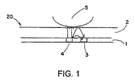
静電容量タッチスクリーン20の一例が、図1に示されている。タッチスクリーンは、導電検知層1がコーティングされた基板(図示せず)を含みうる。基板は、一般的に、インジウムスズ酸化物、または、導電層にわたって直流電流を伝導できる銅のような導電層でコーティングされうる。静電容量タッチスクリーン20は、水平軸と垂直軸で蓄えた電子の制御フィールドを示し、静電容量を得る。人間の体も、電子を蓄えている電子デバイスであり、このため静電容量も示す。静電容量タッチスクリーン20の「通常の」静電容量フィールド(基準状態)が、誰かの指5等の他の静電容量フィールドによって変更される場合には、静電容量タッチスクリーン20の電子回路が、基準静電容量フィールドの正弦波特性や他の一般的な方法で、歪み(resultant distortion)を測定しうる。タッチスクリーン20が含まれる電子装置に含まれるコントローラは、演算処理のために、基準フィールドの正弦波特性の合成歪みの情報を受けうる。静電容量タッチスクリーン20は、裸の指や、裸の手によって保持された導電デバイス5によって、タッチされることができる。しかし、静電容量タッチスクリーン20は、鉛筆の先端や他の類似の物体等の外側の物体の影響を受けない。
An example of a
図1を参照して、静電容量タッチスクリーン20は、指5等のかなり大きい導電性物体や、他の大きい導電性物体を検出しうる。透明なセンサー層1は、ガラススクリーン2の背後に配置されている。指がスクリーンに触れるときに、静電容量が指5とセンサー層1の間に形成される。検出グリッド等のパターンが、指がスクリーンに触れる位置に対応する座標を提供できるように、センサー層1に形成される。
Referring to FIG. 1, the
センサー層1は、電圧を供給する駆動ライン4と、電圧変化を検出する検出ライン3とを含む。指5は、センサー層1の近くのスクリーンへの接触があるときに、アースとして振舞い、電場(E−field)等の電気磁場が、駆動ライン4と指5の間に形成される。この電場は、信号を発生する検出ライン3によって検出される。センサー層1の検出グリッドの複数のラインを走査することで、スクリーン上の指の現在位置が、例えばタッチスクリーンを含む電子機器のCPUによって計算されうる。 The sensor layer 1 includes a drive line 4 that supplies a voltage and a detection line 3 that detects a voltage change. The finger 5 behaves as a ground when there is contact with the screen near the sensor layer 1, and an electric magnetic field such as an electric field (E-field) is formed between the drive line 4 and the finger 5. This electric field is detected by a detection line 3 that generates a signal. By scanning a plurality of lines of the detection grid of the sensor layer 1, the current position of the finger on the screen can be calculated by a CPU of an electronic device including a touch screen, for example.
ここで、以下に示す本発明の様々な実施形態では、感圧デバイス7、導電接触デバイス8を使用するものとする。また、ここで説明されるように、感圧デバイスと導電接触デバイスの両方の使用は、改良されたポインタデバイスを提供する。このポインタデバイスは、静電容量タッチスクリーンと組み合わせて使用されるに適している。
Here, in various embodiments of the present invention described below, the pressure-
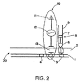
図2は、本発明に係るポインタデバイス6の第1実施形態を示す。ポインタデバイスは、例えば普通サイズのタッチペンケースのようなケーシング9内に取り付けられた導電接触デバイス8と、感圧デバイス7を含む。
FIG. 2 shows a first embodiment of the
図2に示す実施形態では、接触デバイス8は、金属ペン先端である。接触デバイス8は、ユーザがタッチスクリーンに対して接触デバイス8を接触または押下した場合に、タッチスクリーン20の検知層1に容量かく乱を提供するように構成されている。
In the embodiment shown in FIG. 2, the contact device 8 is a metal pen tip. The contact device 8 is configured to provide a capacitive disturbance to the sensing layer 1 of the
金属ペン先端8は、カバー層により被覆され、ポイントデバイスを使用する場合にタッチスクリーンを保護する。カバー層は、例えば、プラスチックやゴム等で作られている。 The metal pen tip 8 is covered with a cover layer to protect the touch screen when using a point device. The cover layer is made of, for example, plastic or rubber.
この実施形態に含まれる感圧デバイス7は、圧電素子の形式である。圧電素子は、圧電特性を有するセラミックス部品またはフィルムでありうる。
The pressure
ペン先端8と圧電素子7は、電気的に接続されている。図3aと図3bで見られるように、圧電素子7は、ペン先端8に対応するように位置している。これにより、タッチスクリーン20に対してポインタデバイス6が押下されたときに、ペン先端8は図3bにおいて矢印で示すように、圧電素子7を押下するために圧電素子7に向かって作動する。圧電素子7は、機械的な衝撃に応じて電圧を生成し、ペン先端が圧電素子で充電され、ペン先端8とタッチスクリーンのセンサー層1の検知ライン3との間に静電容量が形成される。ペン先端8に印加された電圧は、検知ライン3上の電圧変化を検知するために十分な静電容量を超える電場を発生し、この結果、信号を生成する。検知ラインのグリッドは、タッチペンの位置を与える前に走査される。
The pen tip 8 and the
図2に示す非常に単純な電気モデル10において、タッチペン内の圧電素子は、電圧源12として見なされ、検知ライン1とペン先端8の間のギャップは、容量源13と見なされ、ユーザによるポインタデバイスの保持は、アース11の役割をする。
In the very simple
使用時には、ポインタデバイス先端のユーザが、先端をタッチスクリーンの表面に置くと、容量かく乱がタッチスクリーン上で形成される。また、ポインタデバイスのユーザが、例えばタッチスクリーン上で書いたり描いたりするとき、タッチスクリーン上でポインタデバイスを移動させると、タッチスクリーンは、スクリーンを横切るポインタデバイスを検知し、適切なソフトウェアとハードウェアによって文字、数字、他のデータの入力を認識する。 In use, capacitive disturbance is created on the touch screen when the user at the tip of the pointer device places the tip on the surface of the touch screen. In addition, when a user of the pointer device moves, for example, writes or draws on the touch screen, the touch screen detects the pointer device across the screen, and the appropriate software and hardware. Recognizes the input of letters, numbers and other data.
ポインタデバイスは、また、ポインタデバイスの性能を向上/最適させるために、いくつかの追加の受動電気部品または、機械バネ等のいくつかの機械部品を含みうる。 The pointer device may also include some additional passive electrical components or some mechanical components such as mechanical springs to improve / optimize the performance of the pointer device.
ここで用いられる技術は、特定の実施形態を説明するためにのみ用いられ、本発明を限定することを意図しない。ここで用いられるように、単数形「a」、「an」、「the」は、文脈が特段明確に示さない限り、同様に複数形を含むことを意図されている。また、当然のことながら、本明細書では、用語「comprise」、「comprising」、「includes」、および/または「including」は、明記された特徴、整数、ステップ、動作、要素、および/または部品の存在を特定するが、1以上の他の特徴、整数、ステップ、動作、要素、および/または部品の存在または追加を排除しない。 The techniques used herein are used only to illustrate particular embodiments and are not intended to limit the invention. As used herein, the singular forms “a”, “an”, “the” are intended to include the plural forms as well, unless the context clearly indicates otherwise. It should also be understood that, as used herein, the terms “comprise”, “comprising”, “includes”, and / or “including” are the specified features, integers, steps, operations, elements, and / or components. Does not exclude the presence or addition of one or more other features, integers, steps, actions, elements, and / or parts.
他に定義されている場合を除き、ここで用いられる全ての用語(技術的用語と科学的用語を含む)は、本発明が属する分野における当業者によって普通に理解されるような同じ意味を有する。また、当然のことながら、ここで用いられる用語は、本明細書の文脈における意味や従来技術に係る意味を持つように解釈されるべきである。ここで明確に定義されている場合を除き、理想的な意味や過度に形式的な意味に解釈されない。 Except where defined otherwise, all terms used herein (including technical and scientific terms) have the same meaning as commonly understood by one of ordinary skill in the art to which this invention belongs. . It should also be understood that the terms used herein should be interpreted to have the meaning in the context of the present specification and the meaning according to the prior art. Except where clearly defined herein, it is not interpreted in an ideal or overly formal sense.
上記では、本発明の原理、好ましい実施形態、動作モードを説明した。しかし、本発明は、限定されるよりむしろ例示としてみなされるべきであり、前述した特定の実施形態に限定されるべきではない。本発明の様々な実施形態の異なる特徴は、明示的に説明されたもの以外に組み合わせることができる。従って、当然のことながら、以下の特許請求の範囲によって定義される本発明の範囲から逸脱することなく、当業者によってこれらの実施形態において変形を行いうる。
The foregoing has described the principles, preferred embodiments, and modes of operation of the present invention. However, the present invention should be regarded as illustrative rather than limiting and should not be limited to the specific embodiments described above. Different features of the various embodiments of the invention can be combined in addition to those explicitly described. Thus, it will be appreciated that variations may be made in these embodiments by those skilled in the art without departing from the scope of the invention as defined by the following claims.
Claims (8)
導電性ポインタの先端(8)と受動導電素子(7)を有し、
前記導電性ポインタの先端(8)は、前記ポインタデバイス(6)が前記タッチ感知表面に接触する場合に、前記タッチ感知表面に容量かく乱を提供するために前記受動導電素子(7)に電気的に接続される、ポインタデバイス(6)。 A pointer device (6) for use with a capacitive sensing touch screen (20) having a touch sensitive surface comprising:
A conductive pointer tip (8) and a passive conductive element (7);
The tip (8) of the conductive pointer is electrically connected to the passive conductive element (7) to provide capacitive disturbance to the touch sensitive surface when the pointer device (6) contacts the touch sensitive surface. A pointer device (6) connected to
Applications Claiming Priority (3)
| Application Number | Priority Date | Filing Date | Title |
|---|---|---|---|
| US12/101,283 US20090256824A1 (en) | 2008-04-11 | 2008-04-11 | Pointer device for capacitive sensitive touch screens |
| US12/101,283 | 2008-04-11 | ||
| PCT/EP2008/061137 WO2009124602A2 (en) | 2008-04-11 | 2008-08-26 | A pointer device for capacitive sensitive touch screens |
Publications (1)
| Publication Number | Publication Date |
|---|---|
| JP2011516985A true JP2011516985A (en) | 2011-05-26 |
Family
ID=41162290
Family Applications (1)
| Application Number | Title | Priority Date | Filing Date |
|---|---|---|---|
| JP2011503343A Pending JP2011516985A (en) | 2008-04-11 | 2008-08-26 | Pointer device for capacitive sensing touchscreen |
Country Status (6)
| Country | Link |
|---|---|
| US (1) | US20090256824A1 (en) |
| EP (1) | EP2263138A2 (en) |
| JP (1) | JP2011516985A (en) |
| CN (1) | CN101990657A (en) |
| TW (1) | TW200943135A (en) |
| WO (1) | WO2009124602A2 (en) |
Cited By (1)
| Publication number | Priority date | Publication date | Assignee | Title |
|---|---|---|---|---|
| JP2012048437A (en) * | 2010-08-26 | 2012-03-08 | Shin Etsu Polymer Co Ltd | Input pen for capacitive input device |
Families Citing this family (13)
| Publication number | Priority date | Publication date | Assignee | Title |
|---|---|---|---|---|
| US8212795B2 (en) * | 2008-05-21 | 2012-07-03 | Hypercom Corporation | Payment terminal stylus with touch screen contact detection |
| US9389724B2 (en) | 2010-09-09 | 2016-07-12 | 3M Innovative Properties Company | Touch sensitive device with stylus support |
| US10019119B2 (en) | 2010-09-09 | 2018-07-10 | 3M Innovative Properties Company | Touch sensitive device with stylus support |
| US9823785B2 (en) | 2010-09-09 | 2017-11-21 | 3M Innovative Properties Company | Touch sensitive device with stylus support |
| KR101219273B1 (en) * | 2011-01-14 | 2013-01-08 | 삼성디스플레이 주식회사 | touch screen system |
| CN102622104A (en) * | 2011-01-26 | 2012-08-01 | 汉王科技股份有限公司 | Capacitance stylus capable of sensing pressure |
| CN103168281B (en) | 2011-08-10 | 2016-08-10 | 赛普拉斯半导体公司 | The method and apparatus of the existence of detection conductor |
| US9403399B2 (en) | 2012-06-06 | 2016-08-02 | Milwaukee Electric Tool Corporation | Marking pen |
| US9035919B2 (en) * | 2013-03-15 | 2015-05-19 | Microchip Technology Incorporated | Electrostatics stylus |
| FR3005288B1 (en) | 2013-05-06 | 2015-05-15 | Bic Soc | MANUAL DEVICE ADAPTED FOR A CAPACITIVE SCREEN |
| US20150293615A1 (en) * | 2014-04-09 | 2015-10-15 | Maxim Integrated Products, Inc. | Hybrid pen device and method |
| US10592012B2 (en) * | 2018-02-07 | 2020-03-17 | Mark Gordon Arnold | Five-rectangle method for dispatching touch events from motion-disabled users |
| TWI678292B (en) * | 2019-03-15 | 2019-12-01 | 宏碁股份有限公司 | Pen barrel and pen barrel using method |
Citations (3)
| Publication number | Priority date | Publication date | Assignee | Title |
|---|---|---|---|---|
| JPH05265634A (en) * | 1992-03-24 | 1993-10-15 | Toshiba Corp | Coordinate detector |
| WO1997040488A1 (en) * | 1996-04-04 | 1997-10-30 | Cirque Corporation | Computer input stylus method and apparatus |
| JP2006018505A (en) * | 2004-06-30 | 2006-01-19 | Ntt Docomo Inc | Portable terminal |
Family Cites Families (7)
| Publication number | Priority date | Publication date | Assignee | Title |
|---|---|---|---|---|
| FR2483100B1 (en) * | 1980-05-23 | 1985-12-13 | Option Sa | SCRIPTOR STYLE FOR GRAPHIC TABLET, AT THE SAME TIME AS CAPACITIVE SENSOR |
| US4639720A (en) * | 1981-01-12 | 1987-01-27 | Harris Corporation | Electronic sketch pad |
| WO1999059101A2 (en) * | 1998-05-12 | 1999-11-18 | E-Ink Corporation | Microencapsulated electrophoretic electrostatically-addressed media for drawing device applications |
| US20030095115A1 (en) * | 2001-11-22 | 2003-05-22 | Taylor Brian | Stylus input device utilizing a permanent magnet |
| US7685538B2 (en) * | 2003-01-31 | 2010-03-23 | Wacom Co., Ltd. | Method of triggering functions in a computer application using a digitizer having a stylus and a digitizer system |
| JP2004310482A (en) * | 2003-04-08 | 2004-11-04 | Quasar System Inc | Input element and touchpad input method |
| TWI336854B (en) * | 2006-12-29 | 2011-02-01 | Ibm | Video-based biometric signature data collecting method and apparatus |
-
2008
- 2008-04-11 US US12/101,283 patent/US20090256824A1/en not_active Abandoned
- 2008-08-26 WO PCT/EP2008/061137 patent/WO2009124602A2/en active Application Filing
- 2008-08-26 EP EP08787485A patent/EP2263138A2/en not_active Withdrawn
- 2008-08-26 JP JP2011503343A patent/JP2011516985A/en active Pending
- 2008-08-26 CN CN2008801285792A patent/CN101990657A/en active Pending
- 2008-12-11 TW TW097148268A patent/TW200943135A/en unknown
Patent Citations (3)
| Publication number | Priority date | Publication date | Assignee | Title |
|---|---|---|---|---|
| JPH05265634A (en) * | 1992-03-24 | 1993-10-15 | Toshiba Corp | Coordinate detector |
| WO1997040488A1 (en) * | 1996-04-04 | 1997-10-30 | Cirque Corporation | Computer input stylus method and apparatus |
| JP2006018505A (en) * | 2004-06-30 | 2006-01-19 | Ntt Docomo Inc | Portable terminal |
Cited By (1)
| Publication number | Priority date | Publication date | Assignee | Title |
|---|---|---|---|---|
| JP2012048437A (en) * | 2010-08-26 | 2012-03-08 | Shin Etsu Polymer Co Ltd | Input pen for capacitive input device |
Also Published As
| Publication number | Publication date |
|---|---|
| TW200943135A (en) | 2009-10-16 |
| WO2009124602A3 (en) | 2010-01-28 |
| EP2263138A2 (en) | 2010-12-22 |
| US20090256824A1 (en) | 2009-10-15 |
| CN101990657A (en) | 2011-03-23 |
| WO2009124602A2 (en) | 2009-10-15 |
Similar Documents
| Publication | Publication Date | Title |
|---|---|---|
| JP2011516985A (en) | Pointer device for capacitive sensing touchscreen | |
| US8115744B2 (en) | Multi-point touch-sensitive system | |
| KR101711154B1 (en) | Touch pad with force sensors and actuator feedback | |
| KR101330809B1 (en) | Touch panel and electronic device including the touch panel | |
| US8106891B2 (en) | Multi-point touch-sensitive device | |
| US8139040B2 (en) | Method of operating a multi-point touch-sensitive system | |
| US20090002199A1 (en) | Piezoelectric sensing as user input means | |
| US20140043265A1 (en) | System and method for detecting and interpreting on and off-screen gestures | |
| TW200401220A (en) | Touch sensor | |
| WO2014053695A1 (en) | An apparatus and associated methods for providing electrotactile feedback | |
| US20140247238A1 (en) | System and method for dual mode stylus detection | |
| US20130100072A1 (en) | Touch Panel | |
| CN102841708B (en) | Touch control display panel | |
| US20130113722A1 (en) | Touch sensing apparatus and operating method thereof | |
| KR20110127107A (en) | Hybrid touch screen panel and stylus pen system with multi-touch, high scratch resistance, high resolution and pen pressure sensing function | |
| US20140375599A1 (en) | Touch input system and method | |
| US9965053B2 (en) | Touchpen for capacitive touch panel and method of detecting a position of a touchpen | |
| TWI515632B (en) | Touch-and-play input device and operating method thereof | |
| KR101532403B1 (en) | Resistive type touch film for capacitive touch panel | |
| WO2019017153A1 (en) | Information processing device, information processing method, and program | |
| TWI408940B (en) | Flexible mobile phone | |
| KR20110121992A (en) | Touch screen | |
| KR102129319B1 (en) | Method for processing touch input, machine-readable storage medium and electronic device | |
| KR101494259B1 (en) | Composite touch pannel with appendix and method for detecting touch using therefor | |
| KR20120082995A (en) | Hand writing information input system for mobile devices |
Legal Events
| Date | Code | Title | Description |
|---|---|---|---|
| A977 | Report on retrieval |
Free format text: JAPANESE INTERMEDIATE CODE: A971007 Effective date: 20120621 |
|
| A131 | Notification of reasons for refusal |
Free format text: JAPANESE INTERMEDIATE CODE: A131 Effective date: 20120626 |
|
| A02 | Decision of refusal |
Free format text: JAPANESE INTERMEDIATE CODE: A02 Effective date: 20121120 |