JP2011506109A - How to make a replaceable tool - Google Patents
How to make a replaceable tool Download PDFInfo
- Publication number
- JP2011506109A JP2011506109A JP2010536955A JP2010536955A JP2011506109A JP 2011506109 A JP2011506109 A JP 2011506109A JP 2010536955 A JP2010536955 A JP 2010536955A JP 2010536955 A JP2010536955 A JP 2010536955A JP 2011506109 A JP2011506109 A JP 2011506109A
- Authority
- JP
- Japan
- Prior art keywords
- tool
- positioning mechanism
- intermediate assembly
- creating
- robot
- Prior art date
- Legal status (The legal status is an assumption and is not a legal conclusion. Google has not performed a legal analysis and makes no representation as to the accuracy of the status listed.)
- Pending
Links
Images


Classifications
-
- G—PHYSICS
- G05—CONTROLLING; REGULATING
- G05B—CONTROL OR REGULATING SYSTEMS IN GENERAL; FUNCTIONAL ELEMENTS OF SUCH SYSTEMS; MONITORING OR TESTING ARRANGEMENTS FOR SUCH SYSTEMS OR ELEMENTS
- G05B19/00—Programme-control systems
- G05B19/02—Programme-control systems electric
- G05B19/418—Total factory control, i.e. centrally controlling a plurality of machines, e.g. direct or distributed numerical control [DNC], flexible manufacturing systems [FMS], integrated manufacturing systems [IMS], computer integrated manufacturing [CIM]
- G05B19/41805—Total factory control, i.e. centrally controlling a plurality of machines, e.g. direct or distributed numerical control [DNC], flexible manufacturing systems [FMS], integrated manufacturing systems [IMS], computer integrated manufacturing [CIM] characterised by assembly
-
- B—PERFORMING OPERATIONS; TRANSPORTING
- B25—HAND TOOLS; PORTABLE POWER-DRIVEN TOOLS; MANIPULATORS
- B25J—MANIPULATORS; CHAMBERS PROVIDED WITH MANIPULATION DEVICES
- B25J15/00—Gripping heads and other end effectors
- B25J15/04—Gripping heads and other end effectors with provision for the remote detachment or exchange of the head or parts thereof
-
- B—PERFORMING OPERATIONS; TRANSPORTING
- B25—HAND TOOLS; PORTABLE POWER-DRIVEN TOOLS; MANIPULATORS
- B25J—MANIPULATORS; CHAMBERS PROVIDED WITH MANIPULATION DEVICES
- B25J9/00—Programme-controlled manipulators
- B25J9/16—Programme controls
- B25J9/1612—Programme controls characterised by the hand, wrist, grip control
-
- Y—GENERAL TAGGING OF NEW TECHNOLOGICAL DEVELOPMENTS; GENERAL TAGGING OF CROSS-SECTIONAL TECHNOLOGIES SPANNING OVER SEVERAL SECTIONS OF THE IPC; TECHNICAL SUBJECTS COVERED BY FORMER USPC CROSS-REFERENCE ART COLLECTIONS [XRACs] AND DIGESTS
- Y02—TECHNOLOGIES OR APPLICATIONS FOR MITIGATION OR ADAPTATION AGAINST CLIMATE CHANGE
- Y02P—CLIMATE CHANGE MITIGATION TECHNOLOGIES IN THE PRODUCTION OR PROCESSING OF GOODS
- Y02P90/00—Enabling technologies with a potential contribution to greenhouse gas [GHG] emissions mitigation
- Y02P90/02—Total factory control, e.g. smart factories, flexible manufacturing systems [FMS] or integrated manufacturing systems [IMS]
-
- Y—GENERAL TAGGING OF NEW TECHNOLOGICAL DEVELOPMENTS; GENERAL TAGGING OF CROSS-SECTIONAL TECHNOLOGIES SPANNING OVER SEVERAL SECTIONS OF THE IPC; TECHNICAL SUBJECTS COVERED BY FORMER USPC CROSS-REFERENCE ART COLLECTIONS [XRACs] AND DIGESTS
- Y10—TECHNICAL SUBJECTS COVERED BY FORMER USPC
- Y10T—TECHNICAL SUBJECTS COVERED BY FORMER US CLASSIFICATION
- Y10T29/00—Metal working
- Y10T29/49—Method of mechanical manufacture
- Y10T29/49826—Assembling or joining
Abstract
交換可能な取付け具を製造する方法が開示され、本方法は、取付け具の部品を製作するステップと、工具中心点を有する工具の動作を制御するためのシステムと一定の幾何学的寸法関係を有する基準部品を選択するステップと、取付け具の部品および基準部品を備える中間アセンブリを製作するステップと、中間アセンブリ上に第1の位置決め機構を作成し、かつ工具支持体上に工具中心点に対する第2の位置決め機構を作成するステップと、第1の位置決め機構および第2の位置決め機構が対応して係合するように、工具支持体および中間アセンブリを組み立てるステップとを含む。
【選択図】図1A method of manufacturing a replaceable fixture is disclosed, the method comprising producing a part of the fixture, a system for controlling the operation of a tool having a tool center point and a certain geometric dimension relationship. Selecting a reference part having, producing an intermediate assembly comprising a fixture part and a reference part, creating a first positioning mechanism on the intermediate assembly, and providing a first position relative to the tool center point on the tool support. Creating two positioning mechanisms and assembling the tool support and intermediate assembly such that the first positioning mechanism and the second positioning mechanism are correspondingly engaged.
[Selection] Figure 1
Description
本発明は、一般に、部品の製造に関し、より具体的には、研摩、バリ取り、材料除去、ならびに他の機械加工および検査作業中に、ワークに対して工具を正確かつ制御可能に位置決めするための方法および交換可能な装置に関する。 The present invention relates generally to the manufacture of parts, and more specifically to accurately and controllably position a tool relative to a workpiece during polishing, deburring, material removal, and other machining and inspection operations. And a replaceable apparatus.
航空機のエンジンで使用されるブリスクなどの複雑な形状をした物品は、ワークからの材料除去を行う特別な形状をした工具類を用いる技法によって製造される。特に注目の例では、ガスタービンエンジンの、一体化された圧縮機のブレード/ディスク(BLISK:ブリスク)構造が、フライス加工および電解加工(ECM)などの加工方法により単一品として製造される。ブリスクなどの加工された部品の研摩およびバリ取りなどの仕上げ加工作業は、これらの高価な部品を損傷しないようにするために必要であり、かつ実施すべきである。ブリスクには複雑な幾何形状が含まれるため、仕上げ作業の多くは手動で行われる。 Articles with complex shapes such as blisks used in aircraft engines are manufactured by techniques using specially shaped tools that remove material from the workpiece. In a particularly notable example, the integrated compressor blade / disk (BLISK) structure of a gas turbine engine is manufactured as a single piece by processing methods such as milling and electrolytic processing (ECM). Finishing operations such as polishing and deburring of machined parts such as blisks are necessary and should be performed to avoid damaging these expensive parts. Since blisks contain complex geometries, many finishing operations are performed manually.
研摩およびバリ取りなどの仕上げ加工作業に対して、ヒトの動作を再現する多軸ロボットが使用されることもあった。例えば、ブリスクなどの複雑な形状の物品のバリ取りを行うために、ロボットアームの端部に空気を動力源とする研摩ベルト工具を用いる従来の多軸ロボットが使用されてきた。しかし、これらの従来のロボットアームは、前にヒトが操作したものと同じ工具を使用して、この作業を行うヒトの動作を再現している。研摩ベルト式研摩工具は、簡単にはアクセスできない重要な幾何学的構造から離間させた状態に保つ必要があるため、この手法は、ブリスクなどの複雑な幾何形状に対する仕上げ作業にロボットを使用することを極度に制限している。固有のベルトの伸びおよびベルトのトラッキングによりその全長および真位置が絶えず変化することに起因して、これらの高価な部品に費用のかかる損傷が生ずるのを回避するために、従来の研摩ベルト工具を、重要な幾何形状から離間した状態に保つ必要がある。これは、ヒトの手と目の協調関係に欠けるロボット的な、または自動の加工システムでは特に問題である。加工工具の伸びおよびトラッキングなど、絶えず変化する真位置および工具状態は、ブリスクなどの重要な部品のロボット研摩およびバリ取りの使用を極度に制限してきた。機械加工または検査作業で使用するための取付け具の個々の部品を製造することには、本来、製造時の許容差および組立の累積により何らかの変動が含まれる。これらの製造時許容差および組立の累積は、従来、機械加工または検査工具中心点の位置変動を生じていた。製造作業では、多数の工具アセンブリ、およびロボットが使用されており、また工具における製造時変動を保証する従来の方法は、ブリスクなどの複雑な幾何形状の部品内で、工具中心点の正確な位置および制御を保証するには適切なものではない。 For finishing work such as polishing and deburring, a multi-axis robot that reproduces human movement has been used. For example, a conventional multi-axis robot using an abrasive belt tool powered by air at the end of a robot arm has been used to deburr articles having a complicated shape such as blisk. However, these conventional robot arms reproduce the human motion of performing this task using the same tools that were previously operated by the human. This technique requires that the robot be used to finish complex geometries such as blisks because abrasive belt type abrasive tools must be kept away from critical geometric structures that are not easily accessible. Is extremely limited. In order to avoid costly damage to these expensive parts due to constant changes in their overall length and true position due to inherent belt stretch and belt tracking, conventional abrasive belt tools are used. Need to be kept away from important geometric shapes. This is particularly a problem with robotic or automatic processing systems that lack the coordination of human hands and eyes. Continuously changing true positions and tool conditions, such as machining tool elongation and tracking, have severely limited the use of robotic polishing and deburring of critical parts such as blisks. Manufacturing individual parts of fixtures for use in machining or inspection operations inherently involves some variation due to manufacturing tolerances and assembly accumulation. These manufacturing tolerances and assembly accumulations have traditionally resulted in variations in machining or inspection tool center points. In manufacturing operations, many tool assemblies and robots are used, and the traditional method of guaranteeing manufacturing variations in tools is the accurate positioning of the tool center point within a complex geometric part such as a blisk. And it is not appropriate to guarantee control.
したがって、部品に損傷を生ずることなくブリスクなどの複雑な幾何形状に対して、自動化された仕上げ加工作業を行うためのシステムを有することは望ましいはずである。ベルトの摩耗、伸び、トラッキング、張力変化、および他の原因などの工具状態の変化に関係なく、加工工具の接触点の真位置を空間中で維持する装置を有することは望ましいはずである。ロボットまたは他の自動化されたシステムで自動的に制御できる工具の真位置を空間中で維持することのできる、複雑な幾何形状に対して製造および検査作業で使用する装置を製作する方法を有することは望ましい。工具中心点の位置精度を維持しながら様々な工具を交換できるような工具アセンブリを製造する方法を有することは望ましい。 Therefore, it would be desirable to have a system for performing automated finishing operations on complex geometries such as blisks without causing damage to the parts. It would be desirable to have a device that maintains the true position of the processing tool contact point in space, regardless of changes in tool conditions such as belt wear, elongation, tracking, tension changes, and other causes. To have a method of manufacturing equipment for use in manufacturing and inspection operations on complex geometries that can maintain the true position of a tool in space that can be automatically controlled by a robot or other automated system Is desirable. It would be desirable to have a method of manufacturing a tool assembly that allows various tools to be changed while maintaining the tool center point position accuracy.
上記で述べた必要性は、交換可能な取付け具の製造方法を提供する例示的な諸実施形態により満たすことができ、その方法は、取付け具の部品を製作するステップと、工具中心点を有する工具の動作を制御するためのシステムと一定の幾何学的寸法関係を有する基準部品を選択するステップと、取付け具の部品および基準部品を備える中間アセンブリを製作するステップと、中間アセンブリ上に第1の位置決め機構を作成し、かつ工具支持体上に工具中心点に対する第2の位置決め機構を作成するステップと、第1の位置決め機構および第2の位置決め機構が対応して係合するように、工具支持体および中間アセンブリを組み立てるステップとを含む。 The need described above can be met by exemplary embodiments that provide a method for manufacturing a replaceable fixture, the method comprising fabricating a component of the fixture and a tool center point. Selecting a reference part having a certain geometric dimension relationship with a system for controlling the operation of the tool, producing an intermediate assembly comprising a fixture part and a reference part, and a first on the intermediate assembly And a second positioning mechanism with respect to the tool center point on the tool support, and the first positioning mechanism and the second positioning mechanism are correspondingly engaged with each other. Assembling the support and the intermediate assembly.
他の実施形態では、上記で述べた方法はさらに、駆動システムが中間アセンブリ上を移動するための柔軟性を有するように駆動システムを中間アセンブリ上に取り付けるステップと、工具を駆動システムが駆動できるように、工具支持体上に工具を取り付けるステップとのさらなる諸ステップによりロボット工具を製造するように展開される。 In other embodiments, the method described above further includes mounting the drive system on the intermediate assembly such that the drive system has the flexibility to move over the intermediate assembly, and allowing the drive system to drive the tool. In addition, it is deployed to produce a robot tool by further steps including mounting the tool on the tool support.
本発明として見なされる主題は、本明細書の最終部で詳細に示され、また明確に特許請求される。しかし、本発明は、添付の図面と共に以下の説明を参照することにより、最もよく理解することができる。 The subject matter which is regarded as the invention is set forth in detail at the end of this specification and is specifically claimed. However, the invention can best be understood by referring to the following description in conjunction with the accompanying drawings.
同一の参照番号が、様々な図を通して同様の要素を示す諸図面を参照すると、図1は、ガスタービンエンジンのブリスクのバリ取りを行うためのロボットシステムに関する本発明の例示的な実施形態を示す。従来のロボットアーム14を有する従来のロボット14が図1に示されている。ロボット14は、従来、地面または適切なプラットフォームに取り付けられる。ロボット14は、工具先端座標系19により表される空間における工具先端位置をプログラムするための基準として使用する静止座標系17を有する。加工装置100を保持する取付け具20は、取付けシステム22を用いてロボットアーム16上に取り付けられる。加工装置100および取付けシステム22は、図2〜8でより詳細に示される。加工される部品12は、ロボット座標軸17に関して適切に位置する部品座標軸18を有する適切な取付け具13上に取り付けられる。ロボットアームは、通常、ロボット座標系17に関して、平行移動し、かつ回転するために複数の自由度を有する。同様に、加工される部品12は、従来、座標系18に関して複数の自由度で取り付けることができる。
Referring to the drawings in which like reference numbers indicate like elements throughout the various views, FIG. 1 illustrates an exemplary embodiment of the present invention relating to a robotic system for deburring a gas turbine engine blisk. . A
図1で示す例示的な実施形態では、研摩工具40などの加工工具を駆動する駆動システム30が取付け具20上に取り付けられる。部品12からの材料除去を行うために、研摩工具40などの加工工具は、接触点43で部品と接触する。加工中、または検査中に工具が横断する空間における経路は従来の方法を用いてプログラムされる。しかし、ブリスクなど複雑な幾何形状に対する仕上げ作業では、この普通の工具経路プログラミングは、加工中の接触力から、また工具の摩耗から生ずる工具接触点の真位置における変化のため十分ではない。このことは、部品から除去される材料の量が少ない研摩作業で特にそうである。接触点の真位置が工具の状態とは無関係に絶対的に制御されない限り、ブリスクなどの複雑な部品の込み入った幾何形状における切削痕または加工ミスの危険は高い。図1〜8で示す本発明の例示的な実施形態では、工具の接触点43の真位置の空間的位置は、工具の摩耗、工具ベルトのトラッキング、工具ベルトの張力変化、または他の理由により生ずる可能性のある変動にかかわらず、ロボットまたは他のマシニングセンタの座標系17に関して固定された関係を有する。こうすることにより、ロボット14、またはマシニングセンタ(図示せず)など、自動化された加工システムにおける接触点43の位置をプログラミングすることを可能にし、したがって、接触点位置は、ブリスクなどの複雑な部品の込み入った幾何形状との一定の関係に対して制御可能な方法で予測可能に追従し、それを維持することができる。本明細書で続いて述べるように、本発明の他の態様では、工具の破損、またはベルト張力の損失もしくは弛みなどの事故の間に、部品12が損傷を受けないようにするための安全機構も組み込まれる。
In the exemplary embodiment shown in FIG. 1, a
図1で示す研摩のためのシステムの例示的な実施形態では、研摩ベルト41を用いる研摩工具40は、バリを除去するために、ブリスク表面および縁部の輪郭をたどるようにプログラムされる接触点43で、ブリスク(項目12で示される)と接触する。研摩ベルト41は、駆動システム30により駆動される。駆動システム30は、接触点43の空間的な位置が、部品12の局所的な幾何形状と一定の関係を有し、かつ研摩作業中、一定に維持されるように、柔軟性を有するように取付け具20に取り付けられる。加工中に工具経路の幾何形状を変更させる傾向のある、加工で誘起された力もしくは工具の摩耗、または他の原因のいずれも、駆動システム30に対する特有の取付けシステム中に組み込まれた柔軟性により吸収される。上記のように使用できる柔軟性のある取付けシステムを、続いて本明細書で詳細に説明する。
In the exemplary embodiment of the system for polishing shown in FIG. 1, the
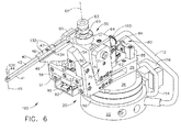
図2、3、および4は、前に述べた駆動システム30を、柔軟性があるように取り付けるための取付け具20の例示的な実施形態の部分的なアセンブリを示す。図5は、取付け具20に取り付けられたモータ60を示す。図6は、取付け具20に取り付けられたモータ60および研摩工具40を備える装置100の組み立てられた図を示す。取付け具の例示的な実施形態は、従来のロボットシステム14またはマシニングセンタ(図示せず)のロボットアーム16に、全体のアセンブリ100を迅速に取り付けるために使用される従来の工具取付けシステム22を備える。アダプタプレート27は、従来の回転アクチュエータ26を工具取付けシステム22に取り付けるために、必要に応じて適宜使用することができる。回転アクチュエータ26は、例えば、図1で示す研摩工具40など、加工工具アセンブリに対して回転の自由度を可能にする。回転アクチュエータは、空気圧供給管路114により供給される空気により動力が与えられる従来の空気圧モータ(図示せず)により駆動される。代替的には、回転アクチュエータ26は、従来の電気モータ(図示せず)により駆動することもできる。
2, 3 and 4 show a partial assembly of an exemplary embodiment of a
ベース25は、加工中に必要に応じて、全体のベース25およびそれに取り付けられる他の部品を、回転アクチュエータ26を用いて回転できるように、回転アクチュエータの上部に、従来の取付け手段を用いて取り付けられる。ベースは、取付けねじを受け入れるためのいくつかのねじ穴を有する中心に配置されたチャネル96を備える。緩衝ブロック88は、ベース25の後側付近でベース25の上部に取り付けられる。レール92は、従来の手段を用いてチャネル96に取り付けられる。前部軸受93および後部軸受94は、軸受93および94が、レール92の長さに沿って摺動できるように、レール上に摺動可能に取り付けられる。軸受93および94は、取付けねじを受け入れることのできるねじ穴をその上部に有する。モータ往復台62が、前部軸受93の上部および後部軸受94の上部に、従来の取付け手段を用いて取り付けられる。全体のモータ往復台62、およびそれに取り付けられるすべての他の部品は、レール92上を、直線的に、前方および後方に移動することができる。加工中に工具が破損したとき生ずる可能性があるなど、モータ往復台が後側方向に一定の指定された位置を越えて移動したとき、モータ往復台の位置を感知するように、近接センサシステムが緩衝ブロック88に取り付けられる。これは、部品12に対する損傷を阻止するために加工作業を停止する安全機構である。近接センサシステムは、緩衝ブロック88に取り付けられたブラケット81と、必要な場合に停止システムを活動化するプランジャ83を有する電気的に動作する従来の近接センサ82とを備える。電気的システムは、電気的モジュール116中に収容される。
The
モータ往復台62は、部分的にその内部に位置するモータハウジング64を受け入れるための空洞部を有する。モータハウジング64は、1対のモータハウジングマウント90を用いて、モータ往復台62に枢動可能に取り付けられる。モータハウジングマウント90は、従来の取付け手段を用いて、その下側端部付近で、モータ往復台64に対してしっかりと取り付けられる。モータ往復台62は、モータハウジングマウント90により支持されるピボット71を各側部に有する。本明細書で示す例示的な実施形態では、ピボット71は、モータ往復台62の側面上の対応する穴と係合する、ハウジングマウント90にその上部付近で取り付けられたねじの形で示されている。他の適切な枢動手段もまた、代替として使用することができる。モータ60は、モータハウジング64内に位置し、取付けねじなどの従来の手段を用いて、モータハウジング内に保持される。図5および6は、空気管路112を介して供給される空気により駆動される空気圧モータ60を示している。空気供給管路112は、クイック接続取付け具110を用いて、空気圧モータ60に接続される。空気圧モータの代わりに、電気モータまたは流体アクチュエータなど、任意の他の適切なタイプの動力システムを使用することもできる。ばねブロック50が、モータ往復台62の前端部に位置する往復台ベース95に対して、従来の手段を用いて取り付けられる。ばねブロック50は、それに取り付けられる圧縮ばね52を有しており、またばねの内側に位置しかつばねブロック50に取り付けられたばねポストを有する。ばねポストは、ばねをガイドし、ばねブロック50およびモータ往復台62に対して力を加えたとき、ばねが座屈しないようにする。図5および7で示す例示的な実施形態では、ばね52は、ばねブロック50中のスロット内に取り付けられる。本明細書で述べるシステムの部品は、軽量な任意の適切な材料、好ましくはアルミニウムを用いて製造することができる。
The
工具取付けシステム22に関して、加工工具の接触点43の真位置を絶対的に位置決めするための、また取付け具20における駆動システム30を柔軟性があるように取り付けるための本発明の例示的な実施形態が、図6〜8で示されている。これらの図を参照すると、立上がりガセット56は、ベース25の前端部に位置しており、従来の取付け手段を用いてベースプレート25の側部に取り付けられる。アーチ型の形状を有する垂直フレーム54が立上がりガセット56に取り付けられており、したがって、立上がりガセットは垂直フレーム54に対して側方支持を提供することができる。垂直フレームはまた、その下側端部で、ベース25の前端部に取り付けることができる。
With respect to the
図6を参照すると、ばねベース51は、垂直フレーム54の前端面に取り付けられる。前に述べたように、ばね52の後端部は、ばねブロック50に取り付けられる。ばね52の前端部は、ばねベース51に取り付けられる。これは、図7で、横断面図で示されている。ばねの前端部は、ばねベース51の中央付近に位置する空洞部内に嵌合し、調整ねじ53により定位置に保持される。加工作業中、本明細書で続いて説明するように、ばね52は、往復台62に取り付けられたばねブロック50に力を加え、往復台を後方に、垂直フレーム54から離れるように押す。調整ねじは、ばねで生成される力の大きさを制御するように調整することができる。
Referring to FIG. 6, the
加工工具の接触点43の真位置は、工具接触アーム42、アームロケータピン47、およびアームマウント49を用いて、空間中に絶対的に位置決めされる。アームマウント49は、従来の手段を用いて垂直フレーム54の上部に剛性を有するように取り付けられる。アームマウントは、加工中、研摩工具40などの加工工具への支持を提供し、レール92に沿って摺動できるモータ往復台62に工具からの反作用力を伝達する。
The true position of the
図6、7、および8は、研摩およびバリ取り工具40を有する、部品を研摩し、かつバリ取りを行うための装置を示す。工具40は、アームクランプ46を用いてアームマウント49に固定された接触アーム42の前端部に取り付けられたローラ44を備える。ローラは、ローラの回転軸45の周りを回転することができる。アームクランプ46は、本明細書で述べるように、アームロケータピン47を用いてアームクランプ上に位置決めされる。工具40は、前端部のローラ44により、かつ後端部のベルト駆動ホイール63により支持された研摩ベルト41を有する。ベルト駆動ホイール63は、駆動モータ60に取り付けられ、回転軸61の周りで回転する。研摩ベルト41は、モータ60およびベルト駆動ホイール63により、ローラ44の周りで駆動される。研摩およびバリ取りの場合、部品12からの材料の除去は、部品12の表面および縁部に対して、動いている研摩ベルト41を接触させることにより達成される。加工中の研摩ベルト41と部品12の間の接触点43の力は、接触アーム42により、アームマウント49および垂直フレーム54へと伝達される。これらの力はレール92に沿って移動することのできるモータ往復台62へと伝達される。研摩ベルトは、2つの回転軸45および61を互いの方向に引っ張る傾向のある張力を有する。これは、調整ねじ53を用いてばね52に設定された圧縮力により対抗され、かつ反作用を受ける。研摩ベルト41の張力は、調整ねじ52を用いて設定される。接触アーム42と、41などの加工工具とを取り付ける特有の方法のため、加工中は常に、空間中の指定された位置に絶対的に位置決めされた工具接触点43の空間的位置が、加工する力または他の工具条件によって、変わることはないことに留意されたい。従来の加工システムにおいて、工具接触点の真位置を変化させるこれらの要因は、本発明では、ばねブロック50を介して往復台62に加えられたばね52からの圧縮力により、レール92上に柔軟性を有するように取り付けられた駆動モータ往復台62の位置を自動的に変化させることによって、吸収される。
FIGS. 6, 7 and 8 show an apparatus for polishing and deburring parts having a polishing and
本発明の一態様では、本明細書で述べられた例示的な実施形態は、加工中の工具の故障、または工具の摩耗状態を検出することができ、かつ加工されている部品12を損傷させることなく加工作業を安全に停止するための手段を提供できる近接センサシステム80を組み込む。近接センサシステム80は、ベース25の後端部付近に位置する緩衝ブロック88に取り付けられた近接ターゲット84と、その後端部付近のモータ往復台上に取り付けられた近接センサ82とを備える。図7を参照すると、加工中に、摩耗、トラックジャンプ、または破損などから研摩ベルト41の張力に大幅な損失があった場合、圧縮ばね52中に蓄えられたエネルギーがばねブロックに対して力を加えて、モータ往復台をレール92に沿って後方に突き出すことになる。近接センサ82は、モータ往復台62の位置を感知し、電気信号をロボットまたはマシニングセンタに送り、システムを安全に停止させるか、あるいは部品12に損傷を与えないように、他の適切な措置をとることになる。モータ往復台62の突然の突出しにより誘起される可能性のあるどんな衝撃荷重も吸収するように、緩衝器およびプランジャが、緩衝ブロック84および近接センサ上に設けられる。
In one aspect of the invention, the exemplary embodiments described herein can detect a tool failure or tool wear condition during processing and damage the
ベルト駆動システムでは、ベルトは、駆動システム軸が適正に位置合せされていない場合、プーリまたは他の駆動体からの軌道をはずれるおそれがある。本発明の態様では、本明細書で述べる例示的な実施形態は、モータの回転軸61の方向付けを調整するための手段を組み込み、またベルト駆動ホイール63における研摩ベルトのトラッキングを調整する。この機構の例示的な実装形態は図8で示されている。本明細書で前に述べたように、駆動モータ60は、モータハウジングピボット71を用いて、マウント90に枢動可能に取り付けられたモータハウジング64内に位置する。さらに、モータハウジング調整ピン72が、モータハウジング64およびモータハウジングマウント90の壁の対応する凹部中に挿入される。調整セットスクリュー76および固定セットスクリュー74が、モータハウジングマウント90内に設けられる。調整セットスクリュー76および固定セットスクリュー74を適切に調整することにより、モータ60の回転軸61の方向付けを、駆動システム30の適正な位置合せのために、必要に応じて変更することができる。ベルト41が作業中に摩耗すると、ベルト駆動ホイール63ベルト溝内のベルトトラッキングが変化する可能性がある。上記で述べた手段を使用して、研摩ベルトがその溝内に留まり、かつローラ44上に維持されることを保証するようにベルトトラッキングを調整することができる。
In a belt drive system, the belt can be off track from a pulley or other drive if the drive system axis is not properly aligned. In aspects of the present invention, the exemplary embodiments described herein incorporate means for adjusting the orientation of the
本発明の他の態様では、ロボットに関する工具中心点の実質的に同じ真位置を維持しながら、異なる取付け具20および異なる工具接触アーム42の完全な交換可能性が達成される。これは、図9で示すように、一連の製造および組立ステップに関する本発明の実施形態を用いて達成される。個々の部品およびその組立の従来の製造法は、製造時許容差および組立の累積により、本来、変動を含んでいる。従来の方法におけるこれらの製造時許容差および組立の累積は、例えば、接触アーム120の先端で表されるものなどの工具中心点の位置の変動を生ずる。工具中心点とは、ロボット14が、ロボットの動作中に制御する、空間における位置決め点のことである。ロボット14は、この工具中心点120の位置、速度、および回転が、製造、検査、および他のロボット用途における指定された目標を達成するのに必要なものとなるように制御する。
In another aspect of the invention, complete interchangeability of
例えば、図6で示すものなど、工具アセンブリを製造する方法200の本発明の例示的な実施形態を、番号202〜224により識別される一連のステップとして図9で示す。番号202の第1のステップでは、図2〜8で示されたベース25、立上がりガセット56、垂直フレーム54などの個々の部品が、従来の手段を用いて製造される。位置決めピン47(図7を参照)用のアーム取付け位置決め孔122、およびアーム位置決め孔132(図6を参照)を除き、個々の部品のすべての特徴が生成される。これらの個々の部品は、次いで、本明細書で前に述べたように組み立てられる(番号204)。取付け具アセンブリは、ロボットもしくは他のマシニングセンタの工具プレート21、または座標系17(図1を参照)に対して位置決めされている他の適切な部品に取り付けられる(番号206)。代替的には、座標系17に関して、同様の位置的特性寸法を有するスレーブ工具プレートなど、等価な工具プレートを使用することもできる。アセンブリ全体は、次いで、アームマウント49中に位置決め孔122を穴開けするために、フライス加工機、またはボール盤などの従来の工作機械上にセットアップされる(番号208)。このセットアップ中に、ロボット工具プレート21(または使用される場合、等価なスレーブ工具プレート)が、機械の原点を設定するために使用される。本発明の例示的な実施形態200のこの機構は、個々の部品加工および組立工程による許容差のどんな累積とも無関係に、ロボット座標系17に対する位置決め孔122および位置決めピン47の真位置の場所が、各取付け具20上で、製造されたものと実質的に同じであることを保証する。前述のセットアップが完了すると、アームマウント49上の位置決め孔122が穴開けされる(番号210)。孔に対するリーマ通しは適宜行われる。取付け孔124が、次いで、アームクランプ46の取付け用として後で使用するために、アームマウント49上に穴開けされる(番号212)。位置決めピン47は、位置決め孔122中に圧入嵌めされる(番号214)。代替的には、位置決めピンは、以下で述べるように、接触アーム上の位置決め孔132中に圧入嵌めすることもできる。位置決め孔122を作成するための本明細書で述べたセットアップを行うことにより、位置決めピン47は、この方法200を用いて製造されるあらゆる取付け具20上で、ロボット座標軸17に関して実質的に同じ空間位置となる。
An exemplary embodiment of the present invention of a
接触アーム42上で、位置決め孔132を穴開けする位置が、次いで、特定される(番号216)。接触アーム42上のこれらの穴位置は、接触アーム42の先端に位置する工具中心点120からの寸法になる。位置決め孔132が、次いで、接触アーム42中に穴開けされる(番号218)。取付け孔134を、さらに接触アーム42中に穴開けすることができる(番号220)。接触アーム位置決め孔132は、次いで、アームマウント49上の位置決めピン122と位置合せされる(番号222)。接触アーム42は、次いで、取付け孔124および134、ならびにキャップヘッドスクリュー48または他の従来の取付け手段を用いて、アームマウント49に取り付けられる(番号224)。
The location on the
本明細書で前に述べたように、ロボット14の場合、ロボットが絶対的に制御する必要のある空間中の唯一の点は、工具中心点120である。ロボット14は、この工具中心点120の位置、速度、および回転を制御する。本明細書で述べたように、接触アーム42上で位置決め孔132を位置決めする特有の方法のために、製造されるあらゆる接触アーム42に関して、工具中心点120から位置決め孔132までの幾何学的関係は、実質的に同じである。方法200に従って製造されるあらゆる取付け具20に対して、位置決めピン47、接触アーム42、および接触アーム工具中心点120は、ロボット座標系17に関して実質的に同じ空間位置にあり、またロボットまたは他のマシニングセンタに対する工具中心点120の幾何学的関係は実質的に同じであるので、製造中に交換可能である。
As previously mentioned herein, for the
本発明の諸実施形態は、本明細書では、研摩工具40などの加工する工具に即して述べられているが、本明細書で開示される部品、アセンブリ、機構、および方法は、例えば、ブリスクなどの複雑な部品の非破壊評価、および寸法検査など、他の状況においても同様に適用可能であることを理解されたい。この記載は、最良の形態を含む本発明を開示するために、また当業者が本発明を製作しかつ使用することを可能にするために、諸例を使用している。本発明の特許性のある範囲は、特許請求の範囲により定義されるが、当業者が想到する他の諸例を含むこともできる。このような他の例は、特許請求の範囲の文言と異なることのない構造的要素を有する場合、または特許請求の範囲の文言と非本質的な差を有する均等な構造的要素を含む場合、特許請求の範囲に含まれることが意図される。
While embodiments of the present invention are described herein with reference to a machining tool, such as
12 部品
13 取付け具
14 ロボット
16 ロボットアーム
17 静止座標系、ロボット座標軸
18 部品座標軸
19 工具先端座標系
20 取付け具
21 工具プレート
22 工具取付けシステム
25 ベース
26 回転アクチュエータ
27 アダプタプレート
30 駆動システム
40 研摩工具
41 研摩ベルト
42 工具接触アーム
43 接触点
44 ローラ
45 ローラの回転軸
46 アームクランプ
47 アームロケータピン
48 キャップヘッドスクリュー
49 アームマウント
50 ばねブロック
51 ばねベース
52 圧縮ばね
53 調整ねじ
54 垂直フレーム
56 立上がりガセット
60 空気圧モータ
61 モータの回転軸
62 モータ往復台
63 ベルト駆動ホイール
64 モータハウジング
71 モータハウジングピボット
72 モータハウジング調整ピン
74 固定セットスクリュー
76 調整セットスクリュー
80 近接センサシステム
81 ブラケット
82 近接センサ
83 プランジャ
84 近接ターゲット
88 緩衝ブロック
90 モータハウジングマウント
92 レール
93 前部軸受
94 後部軸受
95 往復台ベース
96 チャネル
100 加工装置
110 クイック接続取付け具
112 空気供給管路
114 空気圧供給管路
116 電気的モジュール
120 工具中心点
122 アーム取付け位置決め孔
124 取付け孔
132 アーム位置決め孔
134 取付け孔
12
Claims (20)
前記取付け具の部品を製作するステップと、
工具中心点を有する工具の動作を制御するためのシステムと一定の幾何学的寸法関係を有する基準部品を選択するステップと、
前記取付け具の前記部品および前記基準部品を組み立てることにより、中間アセンブリを製作するステップと、
前記中間アセンブリの部品上に第1の位置決め機構を作成するステップと、
前記工具中心点に対する第2の位置決め機構を作成するステップであり、前記第2の位置決め機構が工具支持体上に位置するステップと、
前記第1の位置決め機構および前記第2の位置決め機構が対応して係合するように、前記工具支持体および前記中間アセンブリを組み立てるステップと
を含む方法。 A method of manufacturing a replaceable fixture, comprising:
Producing a part of the fixture;
Selecting a reference part having a fixed geometric dimension relationship with a system for controlling the operation of a tool having a tool center point;
Fabricating an intermediate assembly by assembling the part of the fixture and the reference part;
Creating a first positioning mechanism on a part of the intermediate assembly;
Creating a second positioning mechanism for the tool center point, wherein the second positioning mechanism is located on a tool support;
Assembling the tool support and the intermediate assembly such that the first positioning mechanism and the second positioning mechanism are correspondingly engaged.
取付け具の部品を製作するステップと、
工具中心点を有する工具の動作を制御するためのロボットシステムと一定の幾何学的寸法関係を有する基準部品を選択するステップと、
前記取付け具の前記部品および前記基準部品を組み立てることにより、中間アセンブリを製作するステップと、
前記中間アセンブリの部品上に第1の位置決め機構を作成するステップと、
前記工具中心点に対する第2の位置決め機構を作成するステップであって、前記第2の位置決め機構が工具支持体上に位置する、ステップと、
前記第1の位置決め機構および前記第2の位置決め機構が対応して係合するように、前記工具支持体および前記中間アセンブリを組み立てるステップと、
駆動システムが、前記中間アセンブリ上を移動するための柔軟性を有するように、前記中間アセンブリ上に前記駆動システムを取り付けるステップと、
工具を、前記駆動システムで駆動できるように、前記工具支持体上に取り付けるステップと
を含む方法。 In a method of manufacturing a robot tool,
Producing the parts of the fixture;
Selecting a reference part having a certain geometric dimension relationship with a robot system for controlling the operation of a tool having a tool center point;
Fabricating an intermediate assembly by assembling the part of the fixture and the reference part;
Creating a first positioning mechanism on a part of the intermediate assembly;
Creating a second positioning mechanism for the tool center point, wherein the second positioning mechanism is located on a tool support;
Assembling the tool support and the intermediate assembly such that the first positioning mechanism and the second positioning mechanism are correspondingly engaged;
Mounting the drive system on the intermediate assembly such that the drive system has flexibility to move on the intermediate assembly;
Mounting a tool on the tool support such that a tool can be driven by the drive system.
Applications Claiming Priority (2)
| Application Number | Priority Date | Filing Date | Title |
|---|---|---|---|
| US11/952,487 US20090144958A1 (en) | 2007-12-07 | 2007-12-07 | Method of manufacturing interchangeable tools |
| PCT/US2008/082178 WO2009075964A2 (en) | 2007-12-07 | 2008-11-03 | Method of manufacturing interchangeable tools |
Publications (2)
| Publication Number | Publication Date |
|---|---|
| JP2011506109A true JP2011506109A (en) | 2011-03-03 |
| JP2011506109A5 JP2011506109A5 (en) | 2013-11-14 |
Family
ID=40666704
Family Applications (1)
| Application Number | Title | Priority Date | Filing Date |
|---|---|---|---|
| JP2010536955A Pending JP2011506109A (en) | 2007-12-07 | 2008-11-03 | How to make a replaceable tool |
Country Status (5)
| Country | Link |
|---|---|
| US (1) | US20090144958A1 (en) |
| EP (1) | EP2220543A2 (en) |
| JP (1) | JP2011506109A (en) |
| CA (1) | CA2707079A1 (en) |
| WO (1) | WO2009075964A2 (en) |
Families Citing this family (6)
| Publication number | Priority date | Publication date | Assignee | Title |
|---|---|---|---|---|
| US8512096B2 (en) * | 2007-12-07 | 2013-08-20 | General Electric Company | System for removing material from components |
| US8402625B2 (en) * | 2011-08-30 | 2013-03-26 | General Electric Company | System and method for modifying a rotor |
| CN104615081B (en) * | 2014-12-25 | 2017-05-17 | 哈尔滨汽轮机厂有限责任公司 | Twice centering alignment method for combustion press unit wheel disc blade root grooves |
| KR101982401B1 (en) * | 2017-09-18 | 2019-05-24 | 이태경 | Base plate for installation of robot arm |
| CN108838513B (en) * | 2018-06-20 | 2020-04-17 | 中国民航大学 | Laser processing positioning method |
| CN117428680A (en) * | 2023-12-06 | 2024-01-23 | 丹阳丹金航空材料科技有限公司 | Missile wing mold processing |
Family Cites Families (26)
| Publication number | Priority date | Publication date | Assignee | Title |
|---|---|---|---|---|
| US3491488A (en) * | 1968-01-09 | 1970-01-27 | Sundstrand Engelberg | Belt grinding machine |
| US4654949A (en) * | 1982-02-16 | 1987-04-07 | Diffracto Ltd. | Method for automatically handling, assembling and working on objects |
| US4621398A (en) * | 1982-12-06 | 1986-11-11 | Rockwell International Corporation | Automaton tool mounting system |
| US4512709A (en) * | 1983-07-25 | 1985-04-23 | Cincinnati Milacron Inc. | Robot toolchanger system |
| US4604787A (en) * | 1984-08-15 | 1986-08-12 | Transamerica Delaval Inc. | Tool changer for manipulator arm |
| US4875275A (en) * | 1987-12-07 | 1989-10-24 | Megamation Incoporated | Novel automatic tool changer |
| EP0513223A4 (en) * | 1990-02-06 | 1993-04-07 | General Electric Company | Computer-controlled grinding machine for producing objects with complex shapes |
| US5133156A (en) * | 1990-04-19 | 1992-07-28 | Penn Keystone Corporation | Adjustable belt sander for wood |
| US5077941A (en) * | 1990-05-15 | 1992-01-07 | Space Time Analyses, Ltd. | Automatic grinding method and system |
| JPH04300162A (en) * | 1991-02-08 | 1992-10-23 | Yamaha Motor Co Ltd | Method of finishing surface and device therefor |
| US5386665A (en) * | 1992-09-28 | 1995-02-07 | Clupak, Inc. | Automated/remote control apparatus and method for grinding rubber belts used to compact paper and other web material |
| US5441437A (en) * | 1993-02-18 | 1995-08-15 | Hulstedt; Bryan A. | Compliant constant-force follower device for surface finishing tool |
| DE4310887B4 (en) * | 1993-04-02 | 2004-09-09 | Almi Machinefabriek Vriezenveen B.V. | Device for the end molding of tubular workpieces with different diameters |
| US5460536A (en) * | 1994-07-18 | 1995-10-24 | Applied Robotics, Inc. | Replaceable high power electrical contacts for robotic tool changing systems |
| US5771553A (en) * | 1996-10-03 | 1998-06-30 | National University Of Singapore | Precision and quick affixing method for flexible automated assembly |
| US5830046A (en) * | 1996-10-28 | 1998-11-03 | Vulcan Engineering Co. | Belt shifting idler pulley for reciprocating an abrasive belt |
| US5934974A (en) * | 1997-11-05 | 1999-08-10 | Aplex Group | In-situ monitoring of polishing pad wear |
| JP2000237957A (en) * | 1999-02-22 | 2000-09-05 | Hitachi Seiki Co Ltd | Grinding machine |
| US6602110B2 (en) * | 2001-06-28 | 2003-08-05 | 3M Innovative Properties Company | Automated polishing apparatus and method of polishing |
| US6544112B1 (en) * | 2002-01-17 | 2003-04-08 | Richard Fuchs | Belt tracking adjustment means for belt type abrading machine |
| US6993821B2 (en) * | 2002-12-30 | 2006-02-07 | General Electric Company | Manufacturing cell using tooling apparatus |
| GB2397234A (en) * | 2003-01-20 | 2004-07-21 | Armstrong Healthcare Ltd | A tool holder arrangement |
| FR2864920B1 (en) * | 2004-01-09 | 2006-08-04 | Bruno Leneveu | DEVICE FOR THE ASSEMBLY OF STANDARD ELEMENTS INTENDED FOR THE PRODUCTION OF PRECISION MECHANICAL STRUCTURES |
| EP1757411B1 (en) * | 2004-05-18 | 2010-11-17 | BL Autotec, Ltd. | Master plate and tool plate for robot arm coupling device, and robot arm coupling device |
| CN100436046C (en) * | 2006-02-11 | 2008-11-26 | 鸿富锦精密工业(深圳)有限公司 | Device for replacing grip device |
| US8512096B2 (en) * | 2007-12-07 | 2013-08-20 | General Electric Company | System for removing material from components |
-
2007
- 2007-12-07 US US11/952,487 patent/US20090144958A1/en not_active Abandoned
-
2008
- 2008-11-03 WO PCT/US2008/082178 patent/WO2009075964A2/en active Application Filing
- 2008-11-03 JP JP2010536955A patent/JP2011506109A/en active Pending
- 2008-11-03 CA CA2707079A patent/CA2707079A1/en not_active Abandoned
- 2008-11-03 EP EP08858927A patent/EP2220543A2/en not_active Withdrawn
Also Published As
| Publication number | Publication date |
|---|---|
| WO2009075964A3 (en) | 2009-08-13 |
| CA2707079A1 (en) | 2009-06-18 |
| US20090144958A1 (en) | 2009-06-11 |
| WO2009075964A2 (en) | 2009-06-18 |
| EP2220543A2 (en) | 2010-08-25 |
Similar Documents
| Publication | Publication Date | Title |
|---|---|---|
| CN107234445B (en) | A kind of high speed, in high precision five axis ultrasonic machine tools | |
| JP2011506109A (en) | How to make a replaceable tool | |
| KR20030093119A (en) | Machining apparatus with pivotal workpiece holder | |
| JP2011506108A (en) | System for removing material from parts | |
| WO2011077127A4 (en) | Machine tools and methods of operation thereof | |
| US20140015185A1 (en) | Work processing apparatus | |
| CN210499508U (en) | Five-axis section bar machining center of area cradle formula | |
| TWI481459B (en) | Workpiece having a non-revolution curved surface | |
| JP6917135B2 (en) | Machine Tools | |
| WO2002064323A1 (en) | Tool compliance device and method | |
| JP2011506109A5 (en) | ||
| KR101326249B1 (en) | Hole Drilling Apparatus for Work Piece | |
| WO2012053356A1 (en) | Centering method and device | |
| JP2001219325A (en) | Gentry type machine tool | |
| JP5427159B2 (en) | Processing apparatus and processing method | |
| TWI768194B (en) | work machinery | |
| JP4148166B2 (en) | Contact detection device | |
| JP4874673B2 (en) | Machine Tools | |
| JP4989193B2 (en) | Chamfering device | |
| JP2010184269A (en) | Rotating type plastic working apparatus | |
| CN216575611U (en) | Machine tool for center drilling | |
| CN220593204U (en) | Hydraulic shell feeding manipulator | |
| CN108581638B (en) | Movable machining mechanism for overlong parts | |
| KR101280009B1 (en) | Five axis processing machine install a Laser head | |
| JP5538002B2 (en) | Work processing method and machine tool |
Legal Events
| Date | Code | Title | Description |
|---|---|---|---|
| A521 | Written amendment |
Free format text: JAPANESE INTERMEDIATE CODE: A523 Effective date: 20111101 |
|
| A621 | Written request for application examination |
Free format text: JAPANESE INTERMEDIATE CODE: A621 Effective date: 20111101 |
|
| A131 | Notification of reasons for refusal |
Free format text: JAPANESE INTERMEDIATE CODE: A131 Effective date: 20130326 |
|
| A977 | Report on retrieval |
Free format text: JAPANESE INTERMEDIATE CODE: A971007 Effective date: 20130328 |
|
| A601 | Written request for extension of time |
Free format text: JAPANESE INTERMEDIATE CODE: A601 Effective date: 20130625 |
|
| A602 | Written permission of extension of time |
Free format text: JAPANESE INTERMEDIATE CODE: A602 Effective date: 20130702 |
|
| A524 | Written submission of copy of amendment under section 19 (pct) |
Free format text: JAPANESE INTERMEDIATE CODE: A524 Effective date: 20130925 |
|
| A02 | Decision of refusal |
Free format text: JAPANESE INTERMEDIATE CODE: A02 Effective date: 20131203 |