JP2011504961A - Adhesive sheet and manufacturing method thereof - Google Patents
Adhesive sheet and manufacturing method thereof Download PDFInfo
- Publication number
- JP2011504961A JP2011504961A JP2010536081A JP2010536081A JP2011504961A JP 2011504961 A JP2011504961 A JP 2011504961A JP 2010536081 A JP2010536081 A JP 2010536081A JP 2010536081 A JP2010536081 A JP 2010536081A JP 2011504961 A JP2011504961 A JP 2011504961A
- Authority
- JP
- Japan
- Prior art keywords
- adhesive
- adhesive sheet
- acrylate
- conductive filler
- polymer resin
- Prior art date
- Legal status (The legal status is an assumption and is not a legal conclusion. Google has not performed a legal analysis and makes no representation as to the accuracy of the status listed.)
- Withdrawn
Links
Images


Classifications
-
- C—CHEMISTRY; METALLURGY
- C09—DYES; PAINTS; POLISHES; NATURAL RESINS; ADHESIVES; COMPOSITIONS NOT OTHERWISE PROVIDED FOR; APPLICATIONS OF MATERIALS NOT OTHERWISE PROVIDED FOR
- C09J—ADHESIVES; NON-MECHANICAL ASPECTS OF ADHESIVE PROCESSES IN GENERAL; ADHESIVE PROCESSES NOT PROVIDED FOR ELSEWHERE; USE OF MATERIALS AS ADHESIVES
- C09J9/00—Adhesives characterised by their physical nature or the effects produced, e.g. glue sticks
- C09J9/02—Electrically-conducting adhesives
-
- H—ELECTRICITY
- H05—ELECTRIC TECHNIQUES NOT OTHERWISE PROVIDED FOR
- H05K—PRINTED CIRCUITS; CASINGS OR CONSTRUCTIONAL DETAILS OF ELECTRIC APPARATUS; MANUFACTURE OF ASSEMBLAGES OF ELECTRICAL COMPONENTS
- H05K9/00—Screening of apparatus or components against electric or magnetic fields
-
- C—CHEMISTRY; METALLURGY
- C09—DYES; PAINTS; POLISHES; NATURAL RESINS; ADHESIVES; COMPOSITIONS NOT OTHERWISE PROVIDED FOR; APPLICATIONS OF MATERIALS NOT OTHERWISE PROVIDED FOR
- C09J—ADHESIVES; NON-MECHANICAL ASPECTS OF ADHESIVE PROCESSES IN GENERAL; ADHESIVE PROCESSES NOT PROVIDED FOR ELSEWHERE; USE OF MATERIALS AS ADHESIVES
- C09J133/00—Adhesives based on homopolymers or copolymers of compounds having one or more unsaturated aliphatic radicals, each having only one carbon-to-carbon double bond, and at least one being terminated by only one carboxyl radical, or of salts, anhydrides, esters, amides, imides, or nitriles thereof; Adhesives based on derivatives of such polymers
- C09J133/04—Homopolymers or copolymers of esters
-
- C—CHEMISTRY; METALLURGY
- C09—DYES; PAINTS; POLISHES; NATURAL RESINS; ADHESIVES; COMPOSITIONS NOT OTHERWISE PROVIDED FOR; APPLICATIONS OF MATERIALS NOT OTHERWISE PROVIDED FOR
- C09J—ADHESIVES; NON-MECHANICAL ASPECTS OF ADHESIVE PROCESSES IN GENERAL; ADHESIVE PROCESSES NOT PROVIDED FOR ELSEWHERE; USE OF MATERIALS AS ADHESIVES
- C09J7/00—Adhesives in the form of films or foils
- C09J7/10—Adhesives in the form of films or foils without carriers
-
- C—CHEMISTRY; METALLURGY
- C08—ORGANIC MACROMOLECULAR COMPOUNDS; THEIR PREPARATION OR CHEMICAL WORKING-UP; COMPOSITIONS BASED THEREON
- C08K—Use of inorganic or non-macromolecular organic substances as compounding ingredients
- C08K3/00—Use of inorganic substances as compounding ingredients
- C08K3/02—Elements
- C08K3/08—Metals
-
- C—CHEMISTRY; METALLURGY
- C09—DYES; PAINTS; POLISHES; NATURAL RESINS; ADHESIVES; COMPOSITIONS NOT OTHERWISE PROVIDED FOR; APPLICATIONS OF MATERIALS NOT OTHERWISE PROVIDED FOR
- C09J—ADHESIVES; NON-MECHANICAL ASPECTS OF ADHESIVE PROCESSES IN GENERAL; ADHESIVE PROCESSES NOT PROVIDED FOR ELSEWHERE; USE OF MATERIALS AS ADHESIVES
- C09J2301/00—Additional features of adhesives in the form of films or foils
- C09J2301/40—Additional features of adhesives in the form of films or foils characterized by the presence of essential components
- C09J2301/408—Additional features of adhesives in the form of films or foils characterized by the presence of essential components additives as essential feature of the adhesive layer
-
- C—CHEMISTRY; METALLURGY
- C09—DYES; PAINTS; POLISHES; NATURAL RESINS; ADHESIVES; COMPOSITIONS NOT OTHERWISE PROVIDED FOR; APPLICATIONS OF MATERIALS NOT OTHERWISE PROVIDED FOR
- C09J—ADHESIVES; NON-MECHANICAL ASPECTS OF ADHESIVE PROCESSES IN GENERAL; ADHESIVE PROCESSES NOT PROVIDED FOR ELSEWHERE; USE OF MATERIALS AS ADHESIVES
- C09J2301/00—Additional features of adhesives in the form of films or foils
- C09J2301/40—Additional features of adhesives in the form of films or foils characterized by the presence of essential components
- C09J2301/416—Additional features of adhesives in the form of films or foils characterized by the presence of essential components use of irradiation
-
- C—CHEMISTRY; METALLURGY
- C09—DYES; PAINTS; POLISHES; NATURAL RESINS; ADHESIVES; COMPOSITIONS NOT OTHERWISE PROVIDED FOR; APPLICATIONS OF MATERIALS NOT OTHERWISE PROVIDED FOR
- C09J—ADHESIVES; NON-MECHANICAL ASPECTS OF ADHESIVE PROCESSES IN GENERAL; ADHESIVE PROCESSES NOT PROVIDED FOR ELSEWHERE; USE OF MATERIALS AS ADHESIVES
- C09J2433/00—Presence of (meth)acrylic polymer
Abstract
接着シートの製造方法が開示され、該方法は、(i)接着性ポリマー樹脂形成用モノマーを使用して、ポリマーシロップを形成する工程と、(ii)ポリマーシロップの中に気体を注入して、気泡を形成する工程と、(iii)気泡を有するポリマーシロップに導電性充填剤を混合して、この導電性充填剤をポリマーシロップと混合することによって、接着剤混合物を形成する工程と、(iv)シートの形態の混合物を作製する工程と、(v)シートの少なくとも2つの表面上に光を照射して、接着剤混合物を光重合する工程と、を含む。ポリマーシロップに導電性充填剤を添加する前に、ポリマーシロップの中に気体を注入して気泡を形成することにより、寸法安定性と、比較の接着シートよりも優れた接着力とを有する、電磁放射線を遮蔽及び/又は吸収することが可能な接着シートを得る。A method for producing an adhesive sheet is disclosed, the method comprising: (i) forming a polymer syrup using an adhesive polymer resin-forming monomer; and (ii) injecting a gas into the polymer syrup; Forming a bubble; and (iii) forming an adhesive mixture by mixing a conductive filler with a polymer syrup having bubbles and mixing the conductive filler with the polymer syrup; And (v) irradiating light on at least two surfaces of the sheet to photopolymerize the adhesive mixture. Before adding conductive filler to polymer syrup, by injecting gas into polymer syrup to form air bubbles, it has dimensional stability and better adhesion than comparative adhesive sheet, electromagnetic An adhesive sheet capable of shielding and / or absorbing radiation is obtained.
Description
本発明は、電磁放射線を遮蔽及び/又は吸収することができる接着シートの製造方法に関する。 The present invention relates to a method for producing an adhesive sheet capable of shielding and / or absorbing electromagnetic radiation.
大抵の電子工学製品は、様々な構成要素の組み合わせを含む。そのような電子工学製品を組み立てるときには、これら構成要素がそれぞれの意図する機能を容易に実現できるように、様々な厚さ及び様々な所望の性能特性を有する接着シートを使用する。 Most electronics products include a combination of various components. When assembling such electronics products, adhesive sheets having various thicknesses and various desired performance characteristics are used so that these components can easily achieve their intended functions.
電子工学製品において採用される接着シートは、接着された構成要素がそれらの組み込み関数を実行するように、異なる構成要素を互いに接着し、熱伝導性、電磁波遮蔽特性、及び電磁波吸収特性等の特定の更なる機能特性を示す必要がある。 Adhesive sheets employed in electronics products adhere to different components to each other so that the bonded components perform their built-in functions and identify thermal conductivity, electromagnetic wave shielding properties, and electromagnetic wave absorption properties, etc. It is necessary to show further functional characteristics.
上記機能を実行するために、接着シートは様々な種類の充填剤を含んでもよい。そのような充填剤には、例えば、熱伝導性充填剤、電磁波遮蔽性充填剤、及び電磁吸収充填剤が挙げられる。しかしながら、接着シートの接着力は、充填剤が存在するために有意に低下する可能性がある。 In order to perform the above functions, the adhesive sheet may contain various types of fillers. Such fillers include, for example, thermally conductive fillers, electromagnetic shielding fillers, and electromagnetic absorbing fillers. However, the adhesive strength of the adhesive sheet can be significantly reduced due to the presence of the filler.
これらの問題を解決するために、発泡剤が接着剤に添加されて接着剤の中に気泡が形成され、接着剤の柔軟性及びぬれ性が高められた、新規な接着シートが開発された。 In order to solve these problems, a novel adhesive sheet was developed in which a foaming agent was added to the adhesive to form bubbles in the adhesive, and the flexibility and wettability of the adhesive were increased.
本発明者らは、接着性ポリマー樹脂を導電性充填剤に混合した後に、機械的な発泡プロセスを実施して多孔質構造を形成する、従来のプロセスを介して多孔質構造を有する接着シートを製造すると、導電性充填剤に起因して機械が摩耗し、その結果機械の寿命が短くなることを見出した。 The inventors have prepared an adhesive sheet having a porous structure through a conventional process in which an adhesive polymer resin is mixed with a conductive filler and then a mechanical foaming process is performed to form the porous structure. It has been found that when manufactured, the machine wears due to the conductive filler, resulting in a shortened machine life.
更に、本発明者らは、接着性ポリマー樹脂に多量の導電性充填剤が添加されると、又は導電性充填剤が接着性ポリマー樹脂と長時間混合されると、接着シートの中の気泡が互いに凝集して電気抵抗が大きくなり、圧縮の際に接着シートが容易に変形することを見出した。 Furthermore, the present inventors have found that when a large amount of conductive filler is added to the adhesive polymer resin, or when the conductive filler is mixed with the adhesive polymer resin for a long time, bubbles in the adhesive sheet are formed. It has been found that the electrical resistance increases due to aggregation with each other, and the adhesive sheet is easily deformed during compression.
したがって、本発明者らは、多孔質構造を有する接着シートの製造方法を提供するが、これは、充填剤を有さないポリマーシロップの中に気体を注入し、次に、所定の量の充填剤を接着性ポリマー樹脂と所定の時間混合し、それにより多孔質構造を有する接着シートを製造する。 Accordingly, the inventors provide a method for producing an adhesive sheet having a porous structure, which injects gas into a polymer syrup without a filler and then a predetermined amount of filling. The agent is mixed with the adhesive polymer resin for a predetermined time, thereby producing an adhesive sheet having a porous structure.
本発明の一態様によると、(i)接着性ポリマー樹脂形成用モノマーを使用してポリマーシロップを形成する工程と、(ii)ポリマーシロップの中に気体を注入して、気泡を形成する工程と、(iii)気泡を有するポリマーシロップに導電性充填剤を混合して、接着剤混合物を形成する工程と、(iv)シートの形態の接着剤混合物を作製する工程と、(v)シートの少なくとも一方の表面上に光を照射して、接着剤混合物を光重合する工程と、を含む、接着シートの製造方法が提供される。 According to one aspect of the present invention, (i) a step of forming a polymer syrup using the adhesive polymer resin-forming monomer, and (ii) a step of injecting gas into the polymer syrup to form bubbles. (Iii) mixing a conductive filler with a polymer syrup having air bubbles to form an adhesive mixture; (iv) producing an adhesive mixture in the form of a sheet; and (v) at least of the sheet A method for producing an adhesive sheet, comprising: irradiating light on one surface to photopolymerize an adhesive mixture.
本発明によると、上記製造方法によって製造される接着シートが提供される。 According to this invention, the adhesive sheet manufactured by the said manufacturing method is provided.
一般に、接着性ポリマーシロップの中に気体を注入することによって気泡が形成されると、接着シートは、気泡から形成される多孔質構造を有することができる。このような接着シートの柔軟性は、気泡の存在により改善され得る。接着シートの柔軟性が改善されると、接着シートが圧縮(例えば、接着剤の適用中に発生する)される際の接着シートの広がりを増加させることができ、接着シートの凝集力を不規則な表面上でさえも改善することができ、これにより、接着シートの総合的な接着性能及び特性が改善される。 In general, when bubbles are formed by injecting gas into the adhesive polymer syrup, the adhesive sheet can have a porous structure formed from the bubbles. The flexibility of such an adhesive sheet can be improved by the presence of bubbles. Improved flexibility of the adhesive sheet can increase the spread of the adhesive sheet when the adhesive sheet is compressed (for example, occurs during the application of the adhesive), making the cohesive force of the adhesive sheet irregular Even on smooth surfaces, which improves the overall adhesion performance and properties of the adhesive sheet.
このような多孔質構造を有する接着シートは、導電性充填剤を接着性ポリマー樹脂と混合して接着剤混合物を形成する工程と、接着剤混合物に気体を注入して気泡を形成する工程と、を含む方法を用いて製造することができる。気体は、混合機を使用して機械的に分布され得る。しかしながら、この場合、混合機に搭載されるインペラは、接着剤混合物中に含まれる導電性充填剤によって摩耗され、その結果、混合機の寿命が短くなる。摩耗のために、ユーザーは高価な混合機を購入しなければならず、これにより製造コストが増加する。 The adhesive sheet having such a porous structure includes a step of mixing a conductive filler with an adhesive polymer resin to form an adhesive mixture, a step of injecting gas into the adhesive mixture to form bubbles, It can manufacture using the method containing. The gas can be mechanically distributed using a mixer. However, in this case, the impeller mounted on the mixer is worn by the conductive filler contained in the adhesive mixture, and as a result, the life of the mixer is shortened. Because of wear, the user must purchase an expensive mixer, which increases manufacturing costs.
本発明の方法の一態様によると、導電性充填剤が接着性ポリマー樹脂に混合される前に気泡が形成される。したがって、本発明の接着シートは、気泡から形成される多孔質構造を有することができる。 According to one aspect of the method of the present invention, bubbles are formed before the conductive filler is mixed with the adhesive polymer resin. Therefore, the adhesive sheet of the present invention can have a porous structure formed from bubbles.
気泡がポリマー樹脂の中に形成された後に、導電性充填剤がポリマー樹脂に添加され、混合されると、混合機に搭載されたインペラの摩耗を防ぐことができる。加えて、気泡が既に形成されているポリマー樹脂に導電性充填剤が添加されて、撹拌されると、導電性充填剤をポリマー樹脂の中に均一に分布することができ、ポリマー樹脂の中に新たな気泡が形成されるのを防ぐこと、及び撹拌プロセスの間に既存の気泡が凝集するのを防ぐことの両方が可能である。本発明の方法に従って製造される接着シートは気泡を含有するので、接着シートは改善された凝集特性及び接着特性を示す。これらの方法を用いることで、高価な混合機の寿命を延ばして、接着シートに関連する製造コストを削減することも可能である。 When the conductive filler is added to the polymer resin and mixed after the bubbles are formed in the polymer resin, the impeller mounted on the mixer can be prevented from being worn. In addition, when the conductive filler is added to the polymer resin in which bubbles are already formed and stirred, the conductive filler can be uniformly distributed in the polymer resin, It is possible to both prevent new bubbles from forming and to prevent existing bubbles from agglomerating during the agitation process. Since the adhesive sheet produced according to the method of the present invention contains bubbles, the adhesive sheet exhibits improved agglomeration and adhesive properties. By using these methods, it is possible to extend the life of expensive mixers and reduce the manufacturing costs associated with adhesive sheets.
接着シートに表面及び垂直方向導電性を与えるために、接着性ポリマー樹脂の中に導電性充填剤粒子の連続経路を形成する必要がある。しかしながら、接着性ポリマー樹脂に多量の導電性充填剤を添加して連続経路を形成すると、導電性充填剤の粒子は互いに凝集する傾向があり、それにより接着樹脂の粘度が高くなる。このことは、接着性ポリマー樹脂の物理的性質を有意に低下し得る。 In order to provide surface and vertical conductivity to the adhesive sheet, it is necessary to form a continuous path of conductive filler particles in the adhesive polymer resin. However, when a large amount of conductive filler is added to the adhesive polymer resin to form a continuous path, the conductive filler particles tend to aggregate together, thereby increasing the viscosity of the adhesive resin. This can significantly reduce the physical properties of the adhesive polymer resin.
更に、ポリマーシロップと導電性充填剤の混合時間が長くなるので、一旦均一に分布された可能性がある気泡が凝集する場合があり、又は過度の気泡が生成される場合がある。これにより、導電性充填剤粒子間の連続経路を容易に形成することができず、電気抵抗が大きくなる。 Furthermore, since the mixing time of the polymer syrup and the conductive filler becomes long, bubbles that may have been uniformly distributed may aggregate, or excessive bubbles may be generated. As a result, a continuous path between the conductive filler particles cannot be easily formed, and the electrical resistance increases.
また、気泡含有ポリマーシロップの貯蔵時間が長くなると、分布された気泡がポリマーシロップの表面から排出される可能性があり、接着シート中の気泡の存在が徐々に減少する。このことはまた、接着シートの凝集特性及び接着特性を低下させる傾向がある。 In addition, when the storage time of the bubble-containing polymer syrup increases, the distributed bubbles may be discharged from the surface of the polymer syrup, and the presence of bubbles in the adhesive sheet gradually decreases. This also tends to reduce the cohesive and adhesive properties of the adhesive sheet.
これらの問題を解決するために、本発明は、接着シートに含まれる導電性充填剤の量を制御し、接着性ポリマー樹脂と導電性充填剤の混合時間を制御する。本発明に従って製造される接着シートは、表面及び垂直の両方を呈するので、本発明の接着シートは、電磁放射線を効果的に遮蔽及び/又は吸収することができる。 In order to solve these problems, the present invention controls the amount of the conductive filler contained in the adhesive sheet and controls the mixing time of the adhesive polymer resin and the conductive filler. Since the adhesive sheet produced according to the present invention exhibits both surface and vertical, the adhesive sheet of the present invention can effectively shield and / or absorb electromagnetic radiation.
図1は、本発明の一態様による製造プロセスを描いている。 FIG. 1 depicts a manufacturing process according to one aspect of the present invention.
本発明による接着シートの製造方法は、一般に、(i)接着性ポリマー樹脂形成用モノマーを使用して、ポリマーシロップを形成する工程と、(ii)ポリマーシロップの中に気体を注入して、気泡を形成する工程と、(iii)気泡を有するポリマーシロップに導電性充填剤を混合して、接着剤混合物を形成する工程と、(iv)接着剤混合物をシート状に形成する工程と、(v)接着シートの少なくとも一方の表面上に光を照射して、接着剤混合物を光重合する工程と、を含む。 The method for producing an adhesive sheet according to the present invention generally comprises (i) a step of forming a polymer syrup using an adhesive polymer resin-forming monomer, and (ii) injecting a gas into the polymer syrup, (Iii) mixing a conductive filler with a polymer syrup having air bubbles to form an adhesive mixture, (iv) forming the adhesive mixture into a sheet, and (v ) Irradiating light on at least one surface of the adhesive sheet to photopolymerize the adhesive mixture.
工程(i)では、接着性ポリマー樹脂形成用モノマー類を使用して、典型的な重合を介してポリマーシロップを形成することができる。本発明の実施形態によると、接着性ポリマー樹脂形成用モノマー類は、光開始剤を使用するラジカル重合によって部分的に重合されて、約500cPs〜約2000cPsの範囲の粘度を有する未硬化の、又は半硬化した、ポリマーシロップを形成する。 In step (i), adhesive polymer resin forming monomers can be used to form a polymer syrup via typical polymerization. According to embodiments of the present invention, the adhesive polymer resin-forming monomers are partially polymerized by radical polymerization using a photoinitiator and have an uncured or having a viscosity in the range of about 500 cPs to about 2000 cPs. A semi-cured polymer syrup is formed.
有用な接着性ポリマー樹脂形成用モノマー類は、アクリルポリマー樹脂形成用モノマー類を含む。しかしながら、本発明は、任意の特定の種類の接着性ポリマー樹脂に限定されない。好ましいアクリルポリマー樹脂形成用モノマーには、1〜14個の炭素原子を有するアルキル基を有するアルキルアクリレートエステルモノマー類などの光重合性モノマーが挙げられる。 Useful adhesive polymer resin forming monomers include acrylic polymer resin forming monomers. However, the present invention is not limited to any particular type of adhesive polymer resin. Preferred monomers for forming an acrylic polymer resin include photopolymerizable monomers such as alkyl acrylate ester monomers having an alkyl group having 1 to 14 carbon atoms.
そのようなアルキルアクリレートエステルモノマー類の非限定例には、ブタ(メタ)アクリレート、ヘキシル(メタ)アクリレート、nーオクチル(メタ)アクリレート、イソオクチル(メタ)アクリレート、2−エチルヘキシル(メタ)アクリレート、イソノニル(メタ)アクリレート、イソオクチルアクリレート、イソノニルアクリレート、2−エチルヘキシルアクリレート、デシルアクリレート、ドデシルアクリレート、n−ブチルアクリレート、ヘキシルアクリレート等が挙げられる。 Non-limiting examples of such alkyl acrylate ester monomers include buta (meth) acrylate, hexyl (meth) acrylate, n-octyl (meth) acrylate, isooctyl (meth) acrylate, 2-ethylhexyl (meth) acrylate, isononyl ( Examples include (meth) acrylate, isooctyl acrylate, isononyl acrylate, 2-ethylhexyl acrylate, decyl acrylate, dodecyl acrylate, n-butyl acrylate, hexyl acrylate and the like.
アルキルアクリレートエステルモノマーを単独で使用してポリマーシロップを形成することができるが、アルキルアクリレートエステルモノマー類を1種類以上の極性の共重合性モノマー類と共に使用して、ポリマーシロップを形成してもよい。簡単に言うと、本発明の一実施形態によると、C1〜C14アルキル基と、極性の共重合性モノマーとを有するアルキルアクリレートエステルモノマーを、接着性ポリマー樹脂を形成するためのモノマーとして使用することができる。 Although alkyl acrylate ester monomers can be used alone to form a polymer syrup, alkyl acrylate ester monomers can be used with one or more polar copolymerizable monomers to form a polymer syrup. . Briefly, according to one embodiment of the present invention, a C 1 -C 14 alkyl group, an alkyl acrylate ester monomer and a polar copolymerizable monomer, used as a monomer for forming adhesive polymer resin can do.
この場合、アルキルアクリレートエステルモノマーの極性の共重合性モノマーに対する重量比は任意の特定の範囲又は値に限定されないが、得られる接着性ポリマー樹脂に関して典型的に望ましい物理的特性を考慮すると、99〜50:1〜50が好ましい。 In this case, the weight ratio of the alkyl acrylate ester monomer to the polar copolymerizable monomer is not limited to any particular range or value, but considering the physical properties typically desired for the resulting adhesive polymer resin, 99 to 50: 1 to 50 are preferred.
好適な極性の共重合性モノマーの非限定例としては、アクリル酸、イタコン酸、ヒドロキシアルキルアクリレート、シアノアルキルアクリレート、アクリルアミド、置換アクリルアミド、N−ビニルピロリドン、N−ビニルカプロラクタム、アクリロニトリル、塩化ビニル、フタル酸ジアリル等が挙げられる。 Non-limiting examples of suitable polar copolymerizable monomers include acrylic acid, itaconic acid, hydroxyalkyl acrylate, cyanoalkyl acrylate, acrylamide, substituted acrylamide, N-vinyl pyrrolidone, N-vinyl caprolactam, acrylonitrile, vinyl chloride, phthalate. Examples include diallyl acid.
1種類以上の界面活性剤をまた、ポリマーシロップに添加してもよい。比較的小さな寸法の気泡が気体注入によって生じ、気泡がその形状を維持することができるように、界面活性剤はポリマーシロップの界面に吸着して、ポリマーシロップの表面張力を低下させる。有用な界面活性剤は、典型的には、イオン化の状態及び活性剤の目的によって、アニオン性、カチオン性、双極性イオン、及び非イオン性界面活性剤に分類される。好適な界面活性剤の非限定例には、ポリビニルピロリドン(「PVP」)、ポリエチレンイミン(「PEI」)、ポリビニルメチルエーテル(「PMVE」)、ポリビニルアルコール(「PVA」)、ポリオキシエチレンアルキルフェニルエーテル、ポリオキシエチレンソルビタンモノステアレート、フルオロアクリレート共重合体−エチルアセテート等が挙げられる。界面活性剤の量は、一般に、接着性ポリマー樹脂100部に対して約0.1〜約10部の範囲である。 One or more surfactants may also be added to the polymer syrup. The surfactant adsorbs to the interface of the polymer syrup and lowers the surface tension of the polymer syrup so that relatively small sized bubbles are generated by gas injection and the bubbles can maintain their shape. Useful surfactants are typically classified into anionic, cationic, zwitterionic, and nonionic surfactants, depending on the ionization state and the purpose of the activator. Non-limiting examples of suitable surfactants include polyvinyl pyrrolidone (“PVP”), polyethyleneimine (“PEI”), polyvinyl methyl ether (“PMVE”), polyvinyl alcohol (“PVA”), polyoxyethylene alkylphenyl. Examples include ether, polyoxyethylene sorbitan monostearate, fluoroacrylate copolymer-ethyl acetate, and the like. The amount of surfactant is generally in the range of about 0.1 to about 10 parts per 100 parts of the adhesive polymer resin.
本発明の態様による製造方法の工程(ii)は、ポリマーシロップの中に気泡を形成する工程である。したがって、本発明に従って製造される接着シートは、気泡から形成される多孔質構造を有することができる。ポリマーシロップに多孔質構造を形成する方法には、気体注入を用いた機械的な発泡プロセス、高分子中空微小球体の分布、又は熱発泡剤の使用等が挙げられる。本方法の一実施形態によると、多孔質構造は、気体注入を介した機械的発泡プロセスによってポリマーシロップの中に形成され得る。即ち、気体をポリマーシロップの中に注入しながら混合機を使用する場合、混合機に搭載されたインペラによって気体が均一に分布され、その結果、一般に均一な寸法を有する気泡がポリマーシロップの中に形成される。したがって、接着シートは、気泡から形成される多孔質構造を有することができる。 Step (ii) of the production method according to the embodiment of the present invention is a step of forming bubbles in the polymer syrup. Therefore, the adhesive sheet manufactured according to the present invention can have a porous structure formed from bubbles. Methods for forming a porous structure in a polymer syrup include mechanical foaming processes using gas injection, polymeric hollow microsphere distribution, or the use of thermal foaming agents. According to one embodiment of the method, a porous structure can be formed in the polymer syrup by a mechanical foaming process via gas injection. That is, when a mixer is used while injecting gas into the polymer syrup, the gas is evenly distributed by the impeller mounted on the mixer, and as a result, bubbles having generally uniform dimensions are formed in the polymer syrup. It is formed. Therefore, the adhesive sheet can have a porous structure formed from bubbles.
本発明で使用することができる気体の例には、空気、二酸化炭素、窒素等が挙げられるが、これらに限定されない。 Examples of gases that can be used in the present invention include, but are not limited to, air, carbon dioxide, nitrogen and the like.
気体の流量は、典型的には、約50sccm〜約80sccmの範囲である。気体の流量が過度に低いと、ポリマーシロップの中に気泡が十分に形成されない場合がある。気体の流量が過度に高いと、ポリマーシロップの中に気泡が形成されていない状態で気体が流れ出る場合がある。本発明の一実施形態によると、気体の流量が約500sccmの場合、10μm〜100μmの範囲の平均直径を有する気泡がポリマーシロップの中に形成される。 The gas flow rate typically ranges from about 50 seem to about 80 seem. If the gas flow rate is too low, sufficient bubbles may not be formed in the polymer syrup. If the gas flow rate is excessively high, the gas may flow out in the state where no bubbles are formed in the polymer syrup. According to one embodiment of the present invention, bubbles having an average diameter in the range of 10 μm to 100 μm are formed in the polymer syrup when the gas flow rate is about 500 sccm.
本発明による製造方法の工程(iii)は、工程(ii)で形成された気泡を有するポリマーシロップに導電性充填剤を添加することにより、ポリマーシロップ状の混合物を形成することである。導電性充填剤の材料は特に限定されず、伝導性を付与する働きをするものであれば、本発明において、特定の制限なしにあらゆる充填剤を使用することができる。 Step (iii) of the production method according to the present invention is to form a polymer syrup-like mixture by adding a conductive filler to the polymer syrup having air bubbles formed in step (ii). The material of the conductive filler is not particularly limited, and any filler can be used without specific limitation in the present invention as long as it functions to impart conductivity.
好適な導電性充填材の例には、貴金属と非貴金属とを含む金属、貴金属メッキされた貴金属及び非貴金属、非貴金属メッキされた貴金属及び非貴金属、貴金属又は非金属メッキされた非金属、導電性の非金属、導電性ポリマー、及び上記の任意の2つ以上の混合物が挙げられる。 Examples of suitable conductive fillers include metals including noble and non-noble metals, noble metal-plated noble metals and non-noble metals, non-noble metal plated noble metals and non-noble metals, noble metals or non-metal plated non-metals, conductive Non-metallic, conductive polymers, and mixtures of any two or more of the above.
有用な導電性充填材の特定例には、金、銀及び白金等の貴金属、ニッケル、銅、スズ及びアルミニウム等の非貴金属、銀メッキされた銅、ニッケル、アルミニウム、スズ及び金等の貴金属メッキされた貴金属及び非貴金属、ニッケルメッキされた銅又は銀等の非貴金属メッキされた貴金属及び非貴金属、銀又はニッケルでメッキされたグラファイト、ガラス、セラミックス、プラスチック、エラストマー及び雲母等の貴金属又は非貴金属メッキされた非金属、カーボンブラック及びカーボンファイバー等の導電性非金属、ポリアセチレン、ポリアニリン、ポリピロール、ポリチオフェン、ポリ窒化硫黄、ポリ−p−フェニレン、ポリフェニレンサルファイド、ポリ−p−フェニレンビニレン等の導電性ポリマー、並びに上記の任意の2つ以上の混合物が挙げられる。 Specific examples of useful conductive fillers include noble metals such as gold, silver and platinum, non-noble metals such as nickel, copper, tin and aluminum, noble metal plating such as silver-plated copper, nickel, aluminum, tin and gold Precious and non-precious metals, non-precious metal-plated precious and non-precious metals such as nickel-plated copper or silver, graphite or glass plated with silver or nickel, precious or non-precious metals such as glass, ceramics, plastics, elastomers and mica Conductive polymer such as plated nonmetal, conductive nonmetal such as carbon black and carbon fiber, polyacetylene, polyaniline, polypyrrole, polythiophene, polysulfur nitride, poly-p-phenylene, polyphenylene sulfide, poly-p-phenylene vinylene And any two or more of the above Mixtures thereof.
導電性充填剤は、粒子状の形状を有してもよい。本発明に適応した導電性充填剤の形状は特に制限されず、導電性充填剤の形状を粒子の形に分類することができるなら、どれでも使用することができる。即ち、充填材料が伝導性を提供するためによく使用される従来の充填剤の形状を有する場合は、任意の特別な制限なしにあらゆる形状の充填剤を使用することができる。具体的には、導電性充填剤は、中実微小球、中空微小球、エラストマー粒子、エラストマーバルーン、破片、板、繊維、ロッド、又は不定形の形状を有してもよい。 The conductive filler may have a particulate shape. The shape of the conductive filler adapted to the present invention is not particularly limited, and any shape can be used as long as the shape of the conductive filler can be classified into the shape of particles. That is, any form of filler can be used without any special restrictions, provided that the filler material has a conventional filler shape commonly used to provide conductivity. Specifically, the conductive filler may have solid microspheres, hollow microspheres, elastomer particles, elastomer balloons, debris, plates, fibers, rods, or an irregular shape.
導電性充填剤は、使用する種類に応じて様々な寸法を有してもよい。導電性充填剤の寸法は限定されないが、本発明の一実施形態によると、導電性充填剤は、約0.20μm〜約250μmの範囲の平均直径を有してもよい。更に、導電性充填剤は本発明の別の実施形態によると、約1μm〜約100μmの範囲の平均直径を有してもよい。 The conductive filler may have various dimensions depending on the type used. Although the size of the conductive filler is not limited, according to one embodiment of the present invention, the conductive filler may have an average diameter ranging from about 0.20 μm to about 250 μm. Further, the conductive filler may have an average diameter ranging from about 1 μm to about 100 μm according to another embodiment of the present invention.
本発明の接着シートは、上記導電性充填剤によって伝導性を有し、それにより電磁放射線を遮蔽及び/又は吸収することができる。接着シートがより効果的に電磁波を遮蔽及び/又は吸収できるようにするために、導電性充填剤は、気泡を有するポリマーシロップ中に均一に分布されるのが好ましく、導電性充填材料の粒子間に連続経路が形成されるのが好ましい。例えば、好ましくは、導電性充填剤が接着シートの一方の表面から接着シートの他方の表面まで連続して結合されるように、導電性充填剤はポリマーシロップの厚さ方向及び/又は水平方向に配列される。したがって、本発明による接着シートは、接着シートが電磁放射線を効果的に遮蔽及び/又は吸収することができるように、約0.1Ω/m2〜約50Ω/m2の範囲の表面伝導性、又は約0.01Ω/m2〜約10Ω/m2の範囲の垂直方向導電性を有する。
The adhesive sheet of the present invention is conductive by the conductive filler, and can shield and / or absorb electromagnetic radiation. In order for the adhesive sheet to shield and / or absorb electromagnetic waves more effectively, the conductive filler is preferably distributed evenly in the polymer syrup having bubbles, and between the particles of the conductive filler material. It is preferable that a continuous path is formed. For example, the conductive filler is preferably in the thickness direction and / or horizontal direction of the polymer syrup so that the conductive filler is continuously bonded from one surface of the adhesive sheet to the other surface of the adhesive sheet. Arranged. Accordingly, the adhesive sheet according to the present invention, the adhesive sheet is to be able to shield and / or absorb electromagnetic radiation effectively, the surface conductivity in the range of about 0.1 [Omega /
導電性充填材料の量は、導電性充填剤が実質的に連続した経路を形成するように調整され得る。本発明の一実施形態によると、導電性充填剤の量は、接着性ポリマー樹脂100部に対して約20重量部〜約200重量部の範囲内であってもよい。導電性充填剤の量が約20重量部未満の場合、導電性充填剤はポリマーシロップの中に実質的に連続した経路を形成せず、電磁放射線は効果的に吸収又は遮蔽されない。更に、導電性充填剤の量が約200重量部を超過する場合、接着シートの粘度は実質的に高くなり、接着シート物理的特性は低下し得る。 The amount of conductive filler material can be adjusted so that the conductive filler forms a substantially continuous path. According to one embodiment of the present invention, the amount of conductive filler may be in the range of about 20 parts by weight to about 200 parts by weight with respect to 100 parts of the adhesive polymer resin. When the amount of conductive filler is less than about 20 parts by weight, the conductive filler does not form a substantially continuous path in the polymer syrup and electromagnetic radiation is not effectively absorbed or shielded. Furthermore, if the amount of conductive filler exceeds about 200 parts by weight, the viscosity of the adhesive sheet can be substantially increased and the physical properties of the adhesive sheet can be reduced.
更に、本発明の方法の工程(iii)では、気泡は互いに凝集する傾向にあり、凝集した気泡は、本来であればポリマーシロップ中に実質的に連続した経路を形成する導電性充填剤に支障をもたらす可能性がある。これを防止するため、導電性充填剤と気泡を有するポリマーシロップとの混合時間を約20分以下に維持するのが好ましい。また、導電性充填材料が気泡を有するポリマーシロップの中に十分に分散することを確実にするために、気泡を有するポリマーシロップの中で導電性充填剤を少なくとも約5分間撹拌するのが好ましい。本発明の一実施形態によると、導電性充填剤と気泡を有するポリマーシロップとの混合時間は、約5分〜約20分の範囲である。 Furthermore, in step (iii) of the method of the present invention, the bubbles tend to agglomerate with each other, and the agglomerated bubbles would interfere with the conductive filler that would otherwise form a substantially continuous path in the polymer syrup. May bring about. In order to prevent this, it is preferable to maintain the mixing time of the conductive filler and the polymer syrup having air bubbles to about 20 minutes or less. It is also preferred that the conductive filler be agitated in the bubbled polymer syrup for at least about 5 minutes to ensure that the conductive filler material is well dispersed in the bubbled polymer syrup. According to one embodiment of the present invention, the mixing time of the conductive filler and the polymer syrup having air bubbles ranges from about 5 minutes to about 20 minutes.
接着シートの特性及び有用性が低下しない限り、導電性充填剤材料に加えて、その他の充填剤又充填材を採用することができる。このような追加の充填剤には、熱伝導性充填剤、難燃充填剤、帯電防止剤等が挙げられる。これらの追加の充填剤は、典型的には、接着性ポリマー樹脂100部に対して約100重量部以下、例えば、約10〜100重量部の量で使用することができる。 In addition to the conductive filler material, other fillers or fillers can be employed as long as the properties and usefulness of the adhesive sheet are not deteriorated. Such additional fillers include thermally conductive fillers, flame retardant fillers, antistatic agents, and the like. These additional fillers can typically be used in amounts of up to about 100 parts by weight, for example about 10 to 100 parts by weight, based on 100 parts of the adhesive polymer resin.
本発明の製造方法の工程(iv)では、工程(iii)で形成されたポリマーシロップ混合物は、例えば、テープの形態のシートになる。この場合、透光性の剥離紙又はライナーを使用することができ、混合物は剥離紙とライナーとの間に配置される。剥離紙又はライナーを使用することにより、実質的に無酸素環境を提供することができる。更に、剥離紙又はライナーが遮光パターンを含む場合、剥離紙又はライナーは、ポリマーシロップ混合物に入射する光の透過を制御するためのマスクとしての機能を果たすことができる。 In step (iv) of the production method of the present invention, the polymer syrup mixture formed in step (iii) becomes, for example, a sheet in the form of a tape. In this case, a translucent release paper or liner can be used and the mixture is placed between the release paper and the liner. By using a release paper or liner, a substantially oxygen-free environment can be provided. Further, if the release paper or liner includes a light shielding pattern, the release paper or liner can serve as a mask to control the transmission of light incident on the polymer syrup mixture.
その後、混合物が実質的に無酸素環境下で重合又は架橋されるように、光(好ましくは紫外線)が、遮光パターンを有する剥離紙若しくはライナー又はその他のマスクを介して照射される。好ましくは、シートの両面が実質的に同じ接着力を呈するように、同じ強度を有する光がシートの各表面上に照射される。あるいは、シートの両面が異なる結果として生じる接着力を呈するように、異なる強度を有する光がシートの各表面上に照射され得る。 Thereafter, light (preferably ultraviolet light) is irradiated through a release paper or liner or other mask having a light shielding pattern so that the mixture is polymerized or crosslinked in a substantially oxygen-free environment. Preferably, each surface of the sheet is irradiated with light having the same intensity so that both sides of the sheet exhibit substantially the same adhesion. Alternatively, light having different intensities can be irradiated on each surface of the sheet so that the two sides of the sheet exhibit different resulting adhesions.
シートの両面に光が照射される場合、酸素濃度は約1000ppm以下に保たれるのが好ましい。酸素濃度が低く保たれるので、望ましくない酸化反応が回避されるという理由から、シートは、一般に、良好な接着特性を呈する。混合物を剥離ライナーの間に配置してシートを形成した後、酸素が実質的に除去されたチャンバ、例えば、酸素密度が約1000ppm以下のチャンバ内の遮光パターンのマスクを介して、混合物の上に光を照射してもよい。必要であれば、酸素濃度は約500ppm以下であってもよい。 When light is irradiated on both sides of the sheet, the oxygen concentration is preferably kept at about 1000 ppm or less. Sheets generally exhibit good adhesion properties because undesirable oxidation reactions are avoided because the oxygen concentration is kept low. After the mixture is placed between release liners to form a sheet, it is placed on top of the mixture through a mask with a light shielding pattern in a chamber in which oxygen is substantially removed, for example, a chamber having an oxygen density of about 1000 ppm or less. You may irradiate light. If necessary, the oxygen concentration may be about 500 ppm or less.
剥離層又は低い表面エネルギーコーティングを含む透明なプラスチックフィルムを、透光性の剥離紙又はライナーとして使用してもよい。有用な透光性の剥離紙又はライナーには、ポリエチレンフィルム、ポリプロピレンフィルム、及びポリエチレンテレフタレート(「PET」)フィルムが挙げられる。 A transparent plastic film containing a release layer or low surface energy coating may be used as a translucent release paper or liner. Useful translucent release papers or liners include polyethylene films, polypropylene films, and polyethylene terephthalate (“PET”) films.
透光性の剥離紙又はライナーに加え、光をシートの選択された部分のみに照射するために、遮光パターンのマスクを使用することもできる。このようなマスクは、一般に、光が通過できる1つ以上の領域と、光が通過できない又は非常に少量の光のみが通過できる1つ以上の領域と、を含む。このようなマスクの例には、所定の遮光パターンがその上に形成された透光性の剥離紙又はライナー、ネットメッシュ、及び格子が挙げられる。 In addition to the translucent release paper or liner, a mask with a light shielding pattern may be used to irradiate only selected portions of the sheet. Such masks generally include one or more areas through which light can pass and one or more areas through which light cannot pass or only a very small amount of light can pass. Examples of such a mask include translucent release paper or liner, a net mesh, and a lattice on which a predetermined light shielding pattern is formed.
本発明の実施で用いる剥離紙、ライナー又はマスクの厚さに、特に制限はない。本発明の一実施形態によると、剥離ライナー又はマスクの厚さは、約5μm〜約2mmの範囲であってもよい。剥離ライナー又はマスクが過度に薄いと、パターンを形成するのが、又は混合物を剥離ライナー又はマスクの上に配置するのが、困難であり得る。反対に、剥離ライナー又はマスクが過度に厚いと、光重合を容易に行うことができない。この理由で、上記範囲内の厚さを有する剥離ライナー又はマスクを使用するのが一般に好ましい。 There is no particular limitation on the thickness of the release paper, liner or mask used in the practice of the present invention. According to one embodiment of the present invention, the release liner or mask thickness may range from about 5 μm to about 2 mm. If the release liner or mask is too thin, it may be difficult to form a pattern or place the mixture on the release liner or mask. Conversely, if the release liner or mask is too thick, photopolymerization cannot be easily performed. For this reason, it is generally preferred to use a release liner or mask having a thickness within the above range.
ポリマーシロップの光重合を行うための光の強度は、光重合に従来適用される任意の強度であってよい。本発明の一実施形態によると、紫外線の強度に対応する光強度が好適に適用される。異なる強度を有する光が接着シートの反対面上に照射されると、接着シートは各表面上に異なる接着力を有することができる。換言すれば、接着シートの一方の表面上に比較的強い光を照射してもよく、シートの反対側表面上に比較的弱い光を照射してもよい。弱い光の強度は、例えば、強い光の強度の約10%〜約90%に相当してもよい。本発明の一実施形態によると、強度5.16mW/cm2を有する光及び強度4.75mW/cm2を有する光をそれぞれ、接着シートの上面及び底面に約520秒間照射する。 The intensity of light for performing the photopolymerization of the polymer syrup may be any intensity conventionally applied to photopolymerization. According to one embodiment of the present invention, a light intensity corresponding to the intensity of ultraviolet light is preferably applied. When light having different intensities is irradiated on the opposite surface of the adhesive sheet, the adhesive sheet can have a different adhesion on each surface. In other words, relatively strong light may be irradiated on one surface of the adhesive sheet, and relatively weak light may be irradiated on the opposite surface of the sheet. The weak light intensity may correspond, for example, to about 10% to about 90% of the strong light intensity. According to an embodiment of the present invention, light having an intensity of 5.16 mW / cm 2 and light having an intensity of 4.75 mW / cm 2 are irradiated on the top and bottom surfaces of the adhesive sheet for about 520 seconds, respectively.
本発明による接着シートの厚さは制限されないが、接着シートは、重合中に架橋を形成することが可能な厚さを有するのが好ましい。一例として、接着シートの厚さは約3nm以下であるが、より大きな寸法もまた有用であると考慮される。好ましくは、接着シートの厚さは、約25μm〜3mmの範囲内である。接着シートが過度に薄いと、接着シートの接着力が損なわれる可能性がある。反対に、接着シートが過度に厚いと、電子的構成要素の間の間隔が狭い電子デバイスに接着シートを提供するのが困難であり得る。 The thickness of the adhesive sheet according to the present invention is not limited, but the adhesive sheet preferably has a thickness capable of forming a crosslink during polymerization. As an example, the thickness of the adhesive sheet is about 3 nm or less, although larger dimensions are also considered useful. Preferably, the thickness of the adhesive sheet is in the range of about 25 μm to 3 mm. If the adhesive sheet is too thin, the adhesive strength of the adhesive sheet may be impaired. Conversely, if the adhesive sheet is too thick, it may be difficult to provide the adhesive sheet for electronic devices where the spacing between electronic components is narrow.
本発明による製造方法では、接着性ポリマー樹脂の架橋を実施するために、架橋剤を使用してもよい。接着性ポリマー樹脂の特性、特に、接着性ポリマー樹脂の接着特性は、架橋剤の量に基づいて調整することができる。架橋剤は、接着性ポリマー樹脂100重量部に対して約0.05〜2重量部の量で使用してもよい。使用可能な架橋剤には、1,6−ヘキサンジオールジアクリレート、トリメチロールプロパン、トリアクリレート、ペンタエリスリトールトリアクリレート、1,2−ジエチレングリコールジアクリレート、1,12−ドデカンジオールアクリレートなどの多官能基アクリレートを含むモノマータイプの架橋剤が挙げられる。ただし、本発明はこれらに限定されない。 In the production method according to the present invention, a crosslinking agent may be used for crosslinking the adhesive polymer resin. The properties of the adhesive polymer resin, particularly the adhesive properties of the adhesive polymer resin, can be adjusted based on the amount of the cross-linking agent. You may use a crosslinking agent in the quantity of about 0.05-2 weight part with respect to 100 weight part of adhesive polymer resin. Crosslinkers that can be used include polyfunctional acrylates such as 1,6-hexanediol diacrylate, trimethylolpropane, triacrylate, pentaerythritol triacrylate, 1,2-diethylene glycol diacrylate, 1,12-dodecanediol acrylate, etc. And a monomer type cross-linking agent. However, the present invention is not limited to these.
本発明による製造方法では、光開始剤を使用することができ、採用する光開始剤の量に従ってポリマー樹脂の重合度を調整することができる。光開始剤は、接着剤ポリマー樹脂100重量部に対して約0.01〜約2重量部の量で使用することができる。本発明で使用することができる好適な光開始剤の非限定例には、2,4,6−トリメチルベンゾイル(trimethylebenzoyl)ジフェニホスフィンオキシド、ビス(2,4,6−トリメチルベンゾイル)フェニルフォスフィンオキシド、α,α−メトキシ−α−ヒドロキシアセトフェノン、2−ベンゾイル−2(ジメチルアミノ)−1−[4−(4−モルフォニル)フェニル]−1−ブタノン、2,2−ジメトキシ2−フェニルアセトフェノン等が挙げられるが、これらに限定されない。 In the production method according to the present invention, a photoinitiator can be used, and the degree of polymerization of the polymer resin can be adjusted according to the amount of the photoinitiator employed. The photoinitiator can be used in an amount of about 0.01 to about 2 parts by weight per 100 parts by weight of the adhesive polymer resin. Non-limiting examples of suitable photoinitiators that can be used in the present invention include 2,4,6-trimethylebenzoyl dipheniphosphine oxide, bis (2,4,6-trimethylbenzoyl) phenylphosphine. Oxide, α, α-methoxy-α-hydroxyacetophenone, 2-benzoyl-2 (dimethylamino) -1- [4- (4-morpholinyl) phenyl] -1-butanone, 2,2-dimethoxy-2-phenylacetophenone, etc. However, it is not limited to these.
図2は、本発明の方法に従って製造された接着シートを示す図である。図2に示されるように、接着シートは、接着性ポリマー樹脂1と、この接着性ポリマー樹脂中に均一に分布される接着充填剤2と、を含む。接着性ポリマー樹脂は、気泡3から形成される多孔質構造を有する。接着シートの接着力は、約116N/m(300gf/in)〜約965N/m(2500gf/in)であり、様々な電子用途にこの接着シートを使用することができる。
FIG. 2 is a view showing an adhesive sheet manufactured according to the method of the present invention. As shown in FIG. 2, the adhesive sheet includes an
以下、実施例、比較例及び実験例を具体的に参照して、本発明を更に説明する。実施例、実験例、及び比較例を用いて本発明を説明するが、本発明の範囲はこれらによって限定されるものではない。 Hereinafter, the present invention will be further described with reference to specific examples, comparative examples, and experimental examples. The present invention will be described using examples, experimental examples, and comparative examples, but the scope of the present invention is not limited by these examples.
以下の説明において、「重量部」は、モノマーの重合を介して形成される接着性ポリマー樹脂の構成成分100部に基づいている。 In the following description, “parts by weight” is based on 100 parts of a constituent component of an adhesive polymer resin formed through polymerization of monomers.
実施例1
まず、2−エチルヘキシルアクリレートモノマーと、0.04重量部のイルガキュア(Irgacure)(商標)−651(α,α−メトキシ−α−ヒドロキシアセトフェノン(hydroxyacetphenone)、光開始剤)とを撹拌し、次いで、紫外線ランプを使用して部分的に重合して、2−エチルヘキシルアクリレートプレポリマーを得た。
Example 1
First, a 2-ethylhexyl acrylate monomer and 0.04 parts by weight of Irgacure ™ -651 (α, α-methoxy-α-hydroxyacetophenone, photoinitiator) are stirred, Partial polymerization using an ultraviolet lamp gave a 2-ethylhexyl acrylate prepolymer.
次に、2−エチルヘキシルアクリレートプレポリマー90重量部を1リットルガラス製反応器に投入した後、アクリル酸10重量部、イルガキュア(Irgacure)(商標)−819(ビス(2,4,6−トリメチルベンゾイル)フェニル−ホスフィンオキシド、光開始剤)0.12重量部、1,6−ヘキサンジオールジアクリレート(「HDDA」)(架橋剤)0.1重量部、及びフルオロアクリレート共重合体−エチルアセテート(界面活性剤)0.13重量部を、2−エチルヘキシルアクリレートプレポリマーに混合し、その後十分に撹拌した。その後、紫外線ランプを使用してこの混合物を部分的に重合して、粘度約1700cPsのポリマーシロップを得た。 Next, 90 parts by weight of 2-ethylhexyl acrylate prepolymer was charged into a 1 liter glass reactor, and then 10 parts by weight of acrylic acid, Irgacure ™ -819 (bis (2,4,6-trimethylbenzoyl) ) Phenyl-phosphine oxide, photoinitiator) 0.12 parts by weight, 1,6-hexanediol diacrylate ("HDDA") (crosslinking agent) 0.1 parts by weight, and fluoroacrylate copolymer-ethyl acetate (interface) Activator) 0.13 part by weight was mixed with 2-ethylhexyl acrylate prepolymer and then stirred thoroughly. The mixture was then partially polymerized using an ultraviolet lamp to obtain a polymer syrup having a viscosity of about 1700 cPs.
続いて、窒素ガス(99.99%)を、周波数60Hzの発泡機(冷化工業(Reica Co.)のAP−混合機)を使用して、約500sccmの流量で、ポリマーシロップの中に注入した。ポリマーシロップの密度は0.83g/mLであった。 Subsequently, nitrogen gas (99.99%) was injected into the polymer syrup at a flow rate of about 500 sccm using a 60 Hz frequency foamer (Reica Co. AP-mixer). did. The density of the polymer syrup was 0.83 g / mL.
その後、平均粒径約1μmのニッケル(フィラメント状の導電性充填剤)30重量部を、窒素ガスが注入されたポリマーシロップに混合した。次に、それらを約20分間撹拌して、ポリマーシロップの形態の混合物を生成した。 Thereafter, 30 parts by weight of nickel (filamentous conductive filler) having an average particle diameter of about 1 μm was mixed with the polymer syrup into which nitrogen gas was injected. They were then stirred for about 20 minutes to produce a mixture in the form of a polymer syrup.
ポリマーシロップ状の混合物をガラス製反応器から押し出しながら、ポリプロピレンフィルムで作製された両面硬化用剥離ライナーを、ポリマーシロップ状の混合物の両面に、ロールコーターを使用して、混合物の厚さが約1mmになるように配置した。剥離紙をポリマーシロップ状の混合物の両面に配置することで、混合物が空気、特に、酸素に接触するのを防止した。 While extruding the polymer syrup mixture from the glass reactor, a double-sided curing release liner made of polypropylene film was applied to both sides of the polymer syrup mixture using a roll coater and the thickness of the mixture was about 1 mm. Arranged to be. The release paper was placed on both sides of the polymer syrup mixture to prevent the mixture from coming into contact with air, especially oxygen.
紫外線ランプを使用して、混合物の両面上に、同じ強度の紫外線を520秒間照射して、接着シートを作製した。 An ultraviolet ray lamp was used to irradiate both sides of the mixture with ultraviolet rays having the same intensity for 520 seconds to prepare an adhesive sheet.
比較例1
2−エチルヘキシルアクリレートモノマーと、0.04重量部のイルガキュア(Irgacure)(商標)−651(α,α−メトキシ−α−ヒドロキシアセトフェノン(hydroxyacetphenone)、光開始剤)とを撹拌し、次いで、紫外線ランプを使用して部分的に重合して、2−エチルヘキシルアクリレートプレポリマーを得た。
Comparative Example 1
Stir 2-ethylhexyl acrylate monomer and 0.04 parts by weight of Irgacure ™ -651 (α, α-methoxy-α-hydroxyacetphenone, photoinitiator), then UV lamp Was partially polymerized to give a 2-ethylhexyl acrylate prepolymer.
次に、2−エチルヘキシルアクリレートプレポリマー90重量部を1リットルガラス製反応器に投入した後、アクリル酸10重量部、イルガキュア(Irgacure)(商標)−819(ビス(2,4,6−トリメチルベンゾイル)フェニル−ホスフィンオキシド、光開始剤)0.12重量部、1,6−ヘキサンジオールジアクリレート(「HDDA」)(架橋剤)0.1重量部、及びフルオロアクリレート共重合体−エチルアセテート(界面活性剤)0.13重量部を、2−エチルヘキシルアクリレートプレポリマーに混合し、その後十分に撹拌した。 Next, 90 parts by weight of 2-ethylhexyl acrylate prepolymer was charged into a 1 liter glass reactor, and then 10 parts by weight of acrylic acid, Irgacure ™ -819 (bis (2,4,6-trimethylbenzoyl) ) Phenyl-phosphine oxide, photoinitiator) 0.12 parts by weight, 1,6-hexanediol diacrylate ("HDDA") (crosslinking agent) 0.1 parts by weight, and fluoroacrylate copolymer-ethyl acetate (interface) Activator) 0.13 part by weight was mixed with 2-ethylhexyl acrylate prepolymer and then stirred thoroughly.
その後、平均粒径約1μmのニッケル(フィラメント状の導電性充填剤)30重量部をこの混合物に混合し、次に長時間撹拌して、ポリマーシロップの形態の混合物を作製した。 Thereafter, 30 parts by weight of nickel (filamentary conductive filler) having an average particle size of about 1 μm was mixed with this mixture, and then stirred for a long time to produce a mixture in the form of a polymer syrup.
その後、窒素ガス(99.99%)を、周波数60Hzの発泡機(冷化工業(Reica Co.)のAP−混合機)を使用して、約500sccmの流量で、ポリマーシロップの中に注入した。 Nitrogen gas (99.99%) was then injected into the polymer syrup at a flow rate of about 500 sccm using a 60 Hz frequency foamer (Reica Co. AP-mixer). .
ポリマーシロップ状の混合物をガラス製反応器から押し出しながら、ポリプロピレンフィルムで作製された両面硬化用剥離ライナーを、ポリマーシロップ状の混合物の両面に、ロールコーターを使用して、混合物の厚さが約1mmになるように配置した。剥離ライナーをポリマーシロップ状の混合物の両面に配置することで、混合物が空気、特に、酸素に接触するのを防止した。 While extruding the polymer syrup mixture from the glass reactor, a double-sided curing release liner made of polypropylene film was applied to both sides of the polymer syrup mixture using a roll coater and the thickness of the mixture was about 1 mm. Arranged to be. The release liner was placed on both sides of the polymer syrup mixture to prevent the mixture from coming into contact with air, especially oxygen.
紫外線ランプを使用して、混合物の両面上に、同じ強度の紫外線を520秒間照射して、接着シートを作製した。 An ultraviolet ray lamp was used to irradiate both sides of the mixture with ultraviolet rays having the same intensity for 520 seconds to prepare an adhesive sheet.
比較例2
窒素ガスを混合物の中に注入しなかったことを除いては、比較例1と同じやり方で接着テープを調製した。
Comparative Example 2
An adhesive tape was prepared in the same manner as Comparative Example 1 except that nitrogen gas was not injected into the mixture.
圧縮ひずみ測定
実施例1及び比較例2で製造した接着シートの圧縮ひずみを、次のように測定した。
Compressive strain measurement The compressive strain of the adhesive sheets produced in Example 1 and Comparative Example 2 was measured as follows.
実施例1及び比較例2で製造した接着シートを所望の寸法に切断して準備した。その後、直流抵抗を測定するための金属端子を、万能試験機(「UTM」)の両方のヘッドの間に定置し、試験片をこれら金属端子に取り付けた。両方のヘッドの間の間隔を試験片の厚さだけ狭め、ヘッドを徐々に圧縮し、圧縮力に従った試験片の厚さ変動を測定した。測定結果を、図3に示す。 The adhesive sheets produced in Example 1 and Comparative Example 2 were prepared by cutting to desired dimensions. Thereafter, metal terminals for measuring DC resistance were placed between both heads of a universal testing machine (“UTM”), and test pieces were attached to these metal terminals. The distance between both heads was narrowed by the thickness of the test piece, the head was gradually compressed, and the thickness variation of the test piece according to the compression force was measured. The measurement results are shown in FIG.
この結果に示されているように、比較例2の接着シートは、680000N/m2(45kgf/in2)の力で圧縮すると約50%変形した。実施例1の接着シートは、680000N/m2(45kgf/in2)の力で圧縮すると約30%変形した。 As shown in this result, the adhesive sheet of Comparative Example 2 was deformed by about 50% when compressed with a force of 680000 N / m 2 (45 kgf / in 2 ). The adhesive sheet of Example 1 was deformed by about 30% when compressed with a force of 680000 N / m 2 (45 kgf / in 2 ).
したがって、本発明に従って製造された接着シートは、低圧縮ひずみ、即ち、優れた寸法安定性を有することを認めることができる。 Thus, it can be seen that the adhesive sheet produced according to the present invention has a low compressive strain, i.e. excellent dimensional stability.
抵抗測定
実施例1で製造した接着シートの体積抵抗を、Mil−G−83528表面プローブスキームを使用して測定した。
Resistance Measurement The volume resistance of the adhesive sheet produced in Example 1 was measured using the Mil-G-83528 surface probe scheme.
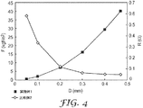
実施例1で製造した接着シートを、寸法2.5cm(1インチ)×2.5cm(1インチ)の正方形片に切断して試験片を準備した。試験片を万能試験機で圧縮した状態で、試験片の体積抵抗を、ケースレー(Kiethely)(商標)580マイクロオームメータ(micro-ohmmeter)を使用して測定した。測定の結果を、図4に示す。 The adhesive sheet manufactured in Example 1 was cut into square pieces having dimensions of 2.5 cm (1 inch) × 2.5 cm (1 inch) to prepare test pieces. With the test piece compressed in a universal tester, the volume resistance of the test piece was measured using a Kiethely ™ 580 micro-ohmmeter. The measurement results are shown in FIG.
この結果に示されるように、実施例1で製造された接着シートが約0.1mmに圧縮されたときの体積抵抗は、約0.32Ωであった。更に、接着シートが約0.3mmに圧縮された場合、実施例1で製造された接着シートの体積抵抗は約0.06Ωであった。 As shown in this result, the volume resistance when the adhesive sheet manufactured in Example 1 was compressed to about 0.1 mm was about 0.32Ω. Furthermore, when the adhesive sheet was compressed to about 0.3 mm, the volume resistance of the adhesive sheet manufactured in Example 1 was about 0.06Ω.
接着力測定
実施例1及び比較例1で製造した接着シートを、ASTM D1000に従ってアルミニウムと組み合わせ、スチールに対する接着シートの接着力を、UTMを使用して180°の方向で測定した。
Adhesive strength measurement The adhesive sheets produced in Example 1 and Comparative Example 1 were combined with aluminum according to ASTM D1000, and the adhesive strength of the adhesive sheet to steel was measured in the direction of 180 ° using UTM.
測定結果として、比較例1で製造した接着シートは、接着力約580N/m(1.5kgf/in)を示し、実施例1で製造した接着シートは、接着力約857N/m(2.23kgf/in)を示した。 As a measurement result, the adhesive sheet manufactured in Comparative Example 1 exhibits an adhesive strength of about 580 N / m (1.5 kgf / in), and the adhesive sheet manufactured in Example 1 has an adhesive strength of about 857 N / m (2.23 kgf). / In).
したがって、本発明による接着シートは、従来の接着シートの接着力より優れた接着力を有することを認めることができる。 Therefore, it can be recognized that the adhesive sheet according to the present invention has an adhesive force superior to that of the conventional adhesive sheet.
本発明の方法に従って、ポリマーシロップに導電性充填剤を添加する前にポリマーシロップの中に気体を注入して気泡を形成することにより、寸法安定性と、比較の接着シートよりも優れた接着力とを有する、電磁放射線を遮蔽及び/又は吸収することが可能な接着シートを得る。 In accordance with the method of the present invention, by adding gas into the polymer syrup to form bubbles before adding the conductive filler to the polymer syrup, dimensional stability and better adhesion than the comparative adhesive sheet An adhesive sheet capable of shielding and / or absorbing electromagnetic radiation is obtained.
本発明のいくつかの好ましい実施形態が説明の目的で記載されてきたが、当業者には、添付の特許請求の範囲に開示されている本発明の範囲及び趣旨から逸脱することなく、様々な修正、追加及び置き換えが可能であることが理解されるであろう。 While several preferred embodiments of the present invention have been described for purposes of illustration, those skilled in the art will recognize that various changes may be made without departing from the scope and spirit of the invention as disclosed in the appended claims. It will be understood that modifications, additions and substitutions are possible.
Claims (23)
(i)接着性ポリマー樹脂形成用モノマーを使用してポリマーシロップを形成する工程と、
(ii)前記ポリマーシロップの中に気体を注入して、気泡を形成する工程と、
(iii)前記気泡を有する前記ポリマーシロップに導電性充填剤を混合して、接着剤混合物を形成する工程と、
(iv)シートの形態の前記接着剤混合物を作製する工程と、
(v)前記シートの少なくとも一方の表面上に光を照射して、前記接着剤混合物を光重合する工程と、を含む方法。 A method for producing an adhesive sheet, comprising:
(I) forming a polymer syrup using an adhesive polymer resin-forming monomer;
(Ii) injecting gas into the polymer syrup to form bubbles;
(Iii) mixing an electrically conductive filler with the polymer syrup having the bubbles to form an adhesive mixture;
(Iv) producing the adhesive mixture in the form of a sheet;
(V) irradiating light on at least one surface of the sheet to photopolymerize the adhesive mixture.
Applications Claiming Priority (2)
| Application Number | Priority Date | Filing Date | Title |
|---|---|---|---|
| KR1020070120938A KR20090054198A (en) | 2007-11-26 | 2007-11-26 | Method for preparing adhesive sheet and adhesive sheet thereby |
| PCT/US2008/084354 WO2009070504A2 (en) | 2007-11-26 | 2008-11-21 | Adhesive sheet and method for manufacturing same |
Publications (2)
| Publication Number | Publication Date |
|---|---|
| JP2011504961A true JP2011504961A (en) | 2011-02-17 |
| JP2011504961A5 JP2011504961A5 (en) | 2012-01-19 |
Family
ID=40679201
Family Applications (1)
| Application Number | Title | Priority Date | Filing Date |
|---|---|---|---|
| JP2010536081A Withdrawn JP2011504961A (en) | 2007-11-26 | 2008-11-21 | Adhesive sheet and manufacturing method thereof |
Country Status (11)
| Country | Link |
|---|---|
| US (1) | US20100317759A1 (en) |
| EP (1) | EP2222809A2 (en) |
| JP (1) | JP2011504961A (en) |
| KR (1) | KR20090054198A (en) |
| CN (1) | CN101874089A (en) |
| BR (1) | BRPI0820399A2 (en) |
| CA (1) | CA2706754A1 (en) |
| MX (1) | MX2010005707A (en) |
| RU (1) | RU2010121725A (en) |
| TW (1) | TW200932867A (en) |
| WO (1) | WO2009070504A2 (en) |
Cited By (1)
| Publication number | Priority date | Publication date | Assignee | Title |
|---|---|---|---|---|
| KR101856214B1 (en) * | 2011-07-28 | 2018-06-25 | 엘지이노텍 주식회사 | Conducting film and manufacturing method of the same |
Families Citing this family (17)
| Publication number | Priority date | Publication date | Assignee | Title |
|---|---|---|---|---|
| KR100608533B1 (en) * | 2005-05-13 | 2006-08-08 | 쓰리엠 이노베이티브 프로퍼티즈 캄파니 | Polymer resin having excellent electroconductivity and manufacturing method thereof |
| KR20080004021A (en) * | 2006-07-04 | 2008-01-09 | 쓰리엠 이노베이티브 프로퍼티즈 캄파니 | Conductive adhesive tape having different adhesion on each surface thereof and method for manufacturing the same |
| CN102470640B (en) * | 2009-08-04 | 2013-06-12 | 新日铁住金株式会社 | Precoated metal plate |
| JPWO2012053373A1 (en) * | 2010-10-22 | 2014-02-24 | リンテック株式会社 | Conductive adhesive composition, electronic device and method for producing electronic device |
| BRPI1005182A2 (en) * | 2010-12-10 | 2013-04-02 | 3M Innovative Properties Co | process for producing one adhesive and process for joining two parts per adhesive |
| JP6146302B2 (en) * | 2011-05-18 | 2017-06-14 | 日立化成株式会社 | Circuit connection material, circuit member connection structure, and circuit member connection structure manufacturing method |
| US9193157B2 (en) | 2011-09-15 | 2015-11-24 | Stratasys Ltd. | Controlling density of dispensed printing material |
| CN102443365B (en) * | 2011-10-16 | 2013-11-06 | 上海晶华粘胶制品发展有限公司 | Adhesive for conductive adhesive tapes, and conductive adhesive tape |
| KR101523817B1 (en) * | 2012-07-10 | 2015-05-28 | (주)엘지하우시스 | Flame retaedant adhesive composition with improved foam stability and the method for manufacturing the same |
| CN103666363B (en) * | 2012-09-10 | 2015-07-08 | 珠海方正科技高密电子有限公司 | Conductive adhesive containing conductive macromolecules and preparation method thereof |
| JP6289831B2 (en) * | 2013-07-29 | 2018-03-07 | デクセリアルズ株式会社 | Manufacturing method of conductive adhesive film, conductive adhesive film, and manufacturing method of connector |
| KR101661583B1 (en) * | 2015-01-20 | 2016-10-10 | (주)창성 | Electromagnetic wave shielding and absorbing sheet and manufacturing method of the same |
| KR102285233B1 (en) | 2015-02-27 | 2021-08-03 | 삼성전자주식회사 | Electronic device |
| EP3138886A1 (en) * | 2015-09-02 | 2017-03-08 | Allnex Belgium S.A. | Method for gluing involving the use of a radiation curable adhesive composition comprising short fibers |
| CN108440938A (en) * | 2018-02-11 | 2018-08-24 | 宁波格林美孚新材料科技有限公司 | A kind of calculus Flexible element conductive material and preparation method thereof |
| CN108913065A (en) * | 2018-05-03 | 2018-11-30 | 南通康尔乐复合材料有限公司 | A kind of conductive fabric glue and preparation method thereof |
| KR20220034661A (en) * | 2020-09-11 | 2022-03-18 | 주식회사 엘지화학 | Adhesive composition for foldable display and adhesive film for foldable display including cured product thereof |
Family Cites Families (16)
| Publication number | Priority date | Publication date | Assignee | Title |
|---|---|---|---|---|
| JPS5826381B2 (en) * | 1979-04-28 | 1983-06-02 | 信越ポリマ−株式会社 | Electromagnetic shield gasket and its manufacturing method |
| US4448837A (en) * | 1982-07-19 | 1984-05-15 | Oki Densen Kabushiki Kaisha | Pressure-sensitive conductive elastic sheet |
| US4548862A (en) * | 1984-09-04 | 1985-10-22 | Minnesota Mining And Manufacturing Company | Flexible tape having bridges of electrically conductive particles extending across its pressure-sensitive adhesive layer |
| JPH06275123A (en) * | 1993-03-18 | 1994-09-30 | Fujitsu Ltd | Conductive filler for capsule type conductive adhesive |
| US5443876A (en) * | 1993-12-30 | 1995-08-22 | Minnesota Mining And Manufacturing Company | Electrically conductive structured sheets |
| US5851644A (en) * | 1995-08-01 | 1998-12-22 | Loctite (Ireland) Limited | Films and coatings having anisotropic conductive pathways therein |
| US6548175B2 (en) * | 2001-01-11 | 2003-04-15 | International Business Machines Corporation | Epoxy-siloxanes based electrically conductive adhesives for semiconductor assembly and process for use thereof |
| US6591496B2 (en) * | 2001-08-28 | 2003-07-15 | 3M Innovative Properties Company | Method for making embedded electrical traces |
| US6784363B2 (en) * | 2001-10-02 | 2004-08-31 | Parker-Hannifin Corporation | EMI shielding gasket construction |
| WO2004086837A1 (en) * | 2003-03-25 | 2004-10-07 | Shin-Etsu Polymer Co., Ltd. | Electromagnetic noise suppressor, article with electromagnetic noise suppression function, and their manufacturing methods |
| KR100626436B1 (en) * | 2003-11-13 | 2006-09-20 | 주식회사 엘지화학 | Adhesives having advanced flame-retardant property |
| CN102277096A (en) * | 2005-03-04 | 2011-12-14 | 索尼化学&信息部件株式会社 | Anisotropic conductive adhesive and method of electrode connection therewith |
| KR100608533B1 (en) * | 2005-05-13 | 2006-08-08 | 쓰리엠 이노베이티브 프로퍼티즈 캄파니 | Polymer resin having excellent electroconductivity and manufacturing method thereof |
| JP2007299907A (en) * | 2006-04-28 | 2007-11-15 | Nitto Denko Corp | Structure having property of conducting or absorbing electromagnetic wave |
| KR20080004021A (en) * | 2006-07-04 | 2008-01-09 | 쓰리엠 이노베이티브 프로퍼티즈 캄파니 | Conductive adhesive tape having different adhesion on each surface thereof and method for manufacturing the same |
| KR101269741B1 (en) * | 2006-07-04 | 2013-05-30 | 쓰리엠 이노베이티브 프로퍼티즈 캄파니 | Electromagnetic wave shielding gasket having elasticity and adhesiveness |
-
2007
- 2007-11-26 KR KR1020070120938A patent/KR20090054198A/en not_active Application Discontinuation
-
2008
- 2008-11-21 CN CN200880117857A patent/CN101874089A/en active Pending
- 2008-11-21 WO PCT/US2008/084354 patent/WO2009070504A2/en active Application Filing
- 2008-11-21 RU RU2010121725/05A patent/RU2010121725A/en not_active Application Discontinuation
- 2008-11-21 MX MX2010005707A patent/MX2010005707A/en unknown
- 2008-11-21 US US12/744,115 patent/US20100317759A1/en not_active Abandoned
- 2008-11-21 CA CA2706754A patent/CA2706754A1/en not_active Abandoned
- 2008-11-21 JP JP2010536081A patent/JP2011504961A/en not_active Withdrawn
- 2008-11-21 EP EP08854975A patent/EP2222809A2/en not_active Withdrawn
- 2008-11-21 BR BRPI0820399-7A patent/BRPI0820399A2/en not_active IP Right Cessation
- 2008-11-25 TW TW097145475A patent/TW200932867A/en unknown
Cited By (1)
| Publication number | Priority date | Publication date | Assignee | Title |
|---|---|---|---|---|
| KR101856214B1 (en) * | 2011-07-28 | 2018-06-25 | 엘지이노텍 주식회사 | Conducting film and manufacturing method of the same |
Also Published As
| Publication number | Publication date |
|---|---|
| CA2706754A1 (en) | 2009-06-04 |
| WO2009070504A2 (en) | 2009-06-04 |
| WO2009070504A3 (en) | 2009-07-23 |
| US20100317759A1 (en) | 2010-12-16 |
| TW200932867A (en) | 2009-08-01 |
| CN101874089A (en) | 2010-10-27 |
| RU2010121725A (en) | 2012-01-10 |
| BRPI0820399A2 (en) | 2015-05-19 |
| KR20090054198A (en) | 2009-05-29 |
| EP2222809A2 (en) | 2010-09-01 |
| MX2010005707A (en) | 2010-06-02 |
Similar Documents
| Publication | Publication Date | Title |
|---|---|---|
| JP2011504961A (en) | Adhesive sheet and manufacturing method thereof | |
| US9336923B2 (en) | Electrically conductive polymer resin and method for making same | |
| CN101485239B (en) | Electromagnetic wave shielding gasket having elasticity and adhesiveness | |
| RU2418833C2 (en) | Current-conducting adhesive tape having various adhesion on both surfaces, and method for its manufacture | |
| WO2007019261A1 (en) | Heat-transferring adhesive tape with improved functionality | |
| JP2011508012A (en) | Adhesive tape and method for producing the same |
Legal Events
| Date | Code | Title | Description |
|---|---|---|---|
| A521 | Request for written amendment filed |
Free format text: JAPANESE INTERMEDIATE CODE: A523 Effective date: 20111121 |
|
| A621 | Written request for application examination |
Free format text: JAPANESE INTERMEDIATE CODE: A621 Effective date: 20111121 |
|
| A761 | Written withdrawal of application |
Free format text: JAPANESE INTERMEDIATE CODE: A761 Effective date: 20120221 |