JP2011502908A - Elevator equipment monitoring method - Google Patents
Elevator equipment monitoring method Download PDFInfo
- Publication number
- JP2011502908A JP2011502908A JP2010516454A JP2010516454A JP2011502908A JP 2011502908 A JP2011502908 A JP 2011502908A JP 2010516454 A JP2010516454 A JP 2010516454A JP 2010516454 A JP2010516454 A JP 2010516454A JP 2011502908 A JP2011502908 A JP 2011502908A
- Authority
- JP
- Japan
- Prior art keywords
- control unit
- signal
- monitoring method
- bus connection
- unit
- Prior art date
- Legal status (The legal status is an assumption and is not a legal conclusion. Google has not performed a legal analysis and makes no representation as to the accuracy of the status listed.)
- Pending
Links
Images


Classifications
-
- B—PERFORMING OPERATIONS; TRANSPORTING
- B66—HOISTING; LIFTING; HAULING
- B66B—ELEVATORS; ESCALATORS OR MOVING WALKWAYS
- B66B13/00—Doors, gates, or other apparatus controlling access to, or exit from, cages or lift well landings
- B66B13/22—Operation of door or gate contacts
-
- B—PERFORMING OPERATIONS; TRANSPORTING
- B66—HOISTING; LIFTING; HAULING
- B66B—ELEVATORS; ESCALATORS OR MOVING WALKWAYS
- B66B5/00—Applications of checking, fault-correcting, or safety devices in elevators
- B66B5/0087—Devices facilitating maintenance, repair or inspection tasks
- B66B5/0093—Testing of safety devices
Abstract
本発明は、制御部(11)と少なくとも1つのバス接続部(13)とを備え、このバス接続部(13)が、受信部(14)と、送信部(15)と、安全要素(16)とを備えるエレベータ装置を監視する方法に関する。制御部(11)とバス接続部(13)とはバス(12)を介して通信する。この監視方法は、デジタル入力信号が制御部(11)から受信部(14)に送信されるステップと、デジタル入力信号が受信部(14)によってアナログ信号に変換されるステップと、アナログ信号が受信部(14)によって安全要素(16)に印加される(16.1)ステップと、安全要素(16)が閉じている場合に、アナログ信号が送信部(15)によって検出される(16.2)ステップと、検出されたアナログ信号ごとに、制御部(11)のデジタル信号が送信部(15)によって提供されるステップと、送信部(15)からのアナログゼロ信号を検出したとき、デジタル信号が制御部(11)に送信されるステップを含む。 The present invention includes a control unit (11) and at least one bus connection unit (13). The bus connection unit (13) includes a reception unit (14), a transmission unit (15), and a safety element (16). For monitoring an elevator apparatus comprising: The control unit (11) and the bus connection unit (13) communicate via the bus (12). In this monitoring method, a digital input signal is transmitted from the control unit (11) to the receiving unit (14), a digital input signal is converted into an analog signal by the receiving unit (14), and the analog signal is received. A step (16.1) applied to the safety element (16) by the part (14) and an analog signal is detected by the transmission part (15) when the safety element (16) is closed (16.2). ) Step, for each detected analog signal, a step in which the digital signal of the control unit (11) is provided by the transmission unit (15), and when an analog zero signal from the transmission unit (15) is detected, the digital signal Is transmitted to the control unit (11).
Description
本発明は特許独立請求項の前文に定義されるエレベータ装置の監視方法に関する。 The invention relates to a method for monitoring an elevator installation as defined in the preamble of the patent independent claim.
従来のエレベータ装置は、直列に接続された安全要素からなる安全回路を有している。これらの安全要素は、例えば、昇降路扉やケージ扉の状態を監視する。そのような安全要素は、接点であってもよい。開放状態の接点は、例えば、扉が開いており、許容できない扉状態が発生した可能性があることを示す。ここで、接点が開いて、許容できない扉の開放状態が確認されると、安全回路が遮断される。これにより、エレベータケージを作動または走行に作用する駆動部やブレーキによってエレベータケージが停止状態になる。 A conventional elevator apparatus has a safety circuit composed of safety elements connected in series. These safety elements, for example, monitor the status of hoistway doors and cage doors. Such a safety element may be a contact. An open contact indicates, for example, that the door is open and an unacceptable door condition may have occurred. Here, when the contact is opened and an unacceptable door open state is confirmed, the safety circuit is interrupted. As a result, the elevator car is stopped by the drive unit and the brake that act on the elevator car to operate or travel.
エレベータ装置用安全システムは国際公開第2005/000727号パンフレットによって知られており、この装置は、制御部はもとより少なくとも1つのバス接続部とバスを備える。バスはバス接続部と制御部との間の通信を可能にする。バス接続部は、例えば、バス接続部の一構成要素である安全要素によって昇降路扉とケージ扉の状態を監視する。さらに、バス接続部は、受信部と送信部とを備える。このとき、受信部は制御部からのデジタルのデフォルト信号を読み取り、それをアナログ信号に変換して安全要素に作用するように設計されている。次に、送信部は、安全要素の後にアナログ信号を測定し、これをデジタル信号に変換する。送信部は、これらのデジタルデータを制御部が利用できるようにする。これらのデータは、バス接続部によってデジタル信号として制御部へ送信されるか、あるいは制御部によって問い合わせにより要求される。 A safety system for an elevator system is known from WO 2005/000727, which comprises at least one bus connection and a bus as well as a control. The bus enables communication between the bus connection and the control unit. A bus connection part monitors the state of a hoistway door and a cage door by the safety element which is one component of a bus connection part, for example. Furthermore, the bus connection unit includes a reception unit and a transmission unit. At this time, the receiving unit is designed to read a digital default signal from the control unit, convert it to an analog signal, and act on the safety element. The transmitter then measures the analog signal after the safety element and converts it to a digital signal. The transmission unit makes these digital data available to the control unit. These data are transmitted as digital signals to the control unit by the bus connection unit or requested by an inquiry from the control unit.
エレベータ装置の安全運転が保証され、エレベータ装置の現在の状態がわかるようにするためには、制御部とバス接続部との間でデジタルデータが短い時間間隔で交換される必要がある。これは、多数のデジタル信号と多数の情報を評価できるようにするために制御部の計算容量を大きくする必要があることを意味している。さらに、バスには、制御部とバス接続部との間で伝送される信号によって大きな負荷がかかるため、データ伝送容量が大きくなっている。 In order to ensure safe operation of the elevator apparatus and to know the current state of the elevator apparatus, digital data needs to be exchanged between the control unit and the bus connection unit in a short time interval. This means that the calculation capacity of the control unit needs to be increased in order to be able to evaluate a large number of digital signals and a large amount of information. Furthermore, since a large load is applied to the bus due to signals transmitted between the control unit and the bus connection unit, the data transmission capacity is increased.
したがって、本発明の目的は、制御部とバス接続部との間のデータ交換が低減されるとともに、制御部の計算容量が低減されるエレベータ装置の監視方法を提供することである。 Accordingly, an object of the present invention is to provide an elevator apparatus monitoring method in which data exchange between a control unit and a bus connection unit is reduced and a calculation capacity of the control unit is reduced.
この目的は独立請求項に定義される本発明によって実現される。 This object is achieved by the invention as defined in the independent claims.
本発明のエレベータ装置の監視方法は、制御部と、少なくとも1つのバス接続部を有している。このバス接続部は、受信部と、送信部と、安全要素とを備える。制御部とバス接続部はバスを介して通信する。この方法は:
デジタルのデフォルト信号が制御部によって受信部に送信されるステップと、
デジタルのデフォルト信号が受信部によってアナログ信号に変換されるステップと、
安全要素が、受信部によってアナログ信号で作用されるステップと、
安全要素が閉じている場合に、アナログ信号が送信部によって検出されるステップと、
検出されたアナログ信号について、制御部のデジタル信号が送信部によって提供されるステップと、
アナログゼロ信号の検出時に、デジタル信号が送信部によって制御部に送信されるステップとを実行する。
The monitoring method for an elevator apparatus according to the present invention includes a control unit and at least one bus connection unit. The bus connection unit includes a reception unit, a transmission unit, and a safety element. The control unit and the bus connection unit communicate via the bus. This method is:
A digital default signal is transmitted by the control unit to the receiving unit;
A step of converting a digital default signal into an analog signal by the receiver;
A safety element is acted on by an analog signal by the receiver;
An analog signal is detected by the transmitter when the safety element is closed; and
For the detected analog signal, a digital signal of the control unit is provided by the transmission unit;
A step of transmitting the digital signal to the control unit by the transmission unit when detecting the analog zero signal;
この監視方法の利点は、制御部とバス接続部との間のデータ交換が少ないことにある。安全要素が開いているとき、したがって、例えば、昇降路扉やケージ扉が開いているときに、バス接続部がこの危険な状態の可能性を制御部に伝えるので、制御部とバス接続部との間の絶え間ない短時間周期の通信が解消される。その結果、計算容量が低減された制御部、並びにデータ伝送容量が低減されたバスを使用することが可能になって、コスト低下につながる。 The advantage of this monitoring method is that there is less data exchange between the control unit and the bus connection unit. When the safety element is open, and thus when the hoistway door or cage door is open, for example, the bus connection communicates the possibility of this dangerous state to the control part, so the control part and the bus connection part The constant short-term communication during the period is eliminated. As a result, it becomes possible to use a control unit with a reduced calculation capacity and a bus with a reduced data transmission capacity, leading to cost reduction.
デジタルのデフォルト信号が制御部によって所定の時間間隔で受信部に送信されると有利である。この時間間隔の間に、安全要素が受信部によって前回のデジタルデフォルト信号に対応するアナログ信号で作用される。通常運転時には、送信部より提供されるデジタル信号が制御部によって所定の時間間隔で問い合わせされる。これらの時間間隔は100秒程度になるように選択されることが好ましい。 Advantageously, a digital default signal is transmitted by the control unit to the receiving unit at predetermined time intervals. During this time interval, the safety element is acted on by the receiver with an analog signal corresponding to the previous digital default signal. During normal operation, a digital signal provided from the transmitter is inquired by the controller at predetermined time intervals. These time intervals are preferably selected to be about 100 seconds.
このようにデフォルト時間間隔と問い合わせ時間間隔とが相対的に長いことの利点は、制御部とバス接続部との間のバスの負担をさらに軽くするとともに、制御部によって処理される信号とデータをさらに少なくすることである。 The advantage of the relatively long default time interval and inquiry time interval is that the load on the bus between the control unit and the bus connection unit is further reduced, and the signals and data processed by the control unit are reduced. It is even less.
アナログゼロ信号の検出時に、デジタル信号が送信部によって自動的に制御部に送信されると有利である。これは、例えば、安全要素が開いて、アナログゼロ信号が送信部によって検出される場合である。デジタル信号の自動送信により、エレベータを安全運転状態にするための手段が制御部によって取られる。 It is advantageous if the digital signal is automatically transmitted to the control unit by the transmission unit upon detection of the analog zero signal. This is the case, for example, when the safety element is open and an analog zero signal is detected by the transmitter. Means for placing the elevator in a safe driving state by automatic transmission of digital signals is taken by the controller.
送信部によって制御部へデジタル信号が自動送信されることの利点は、デフォルト時間間隔と問い合わせ時間間隔が相対的に長いにもかかわらず、エレベータを安全に運転することができるということにある。 The advantage of automatically transmitting the digital signal to the control unit by the transmission unit is that the elevator can be safely operated even though the default time interval and the inquiry time interval are relatively long.
監視方法が検査ステップを含んでいると有利である。この検査ステップでは、バス接続部が制御部によって所定の時間間隔で検査される。この検査ステップは、制御部によって少なくとも1日に1回実行される。その場合、バス接続部は、制御部によってデジタルのゼロデフォルト信号で作用され、このデジタルゼロ信号は受信部によってアナログゼロ信号に変換される。したがって、送信部はアナログゼロ信号を測定する。したがって、正確に機能していれば、対応するデジタル信号がバス接続部によって自動的に制御部に送信される。 It is advantageous if the monitoring method includes an inspection step. In this inspection step, the bus connection unit is inspected at predetermined time intervals by the control unit. This inspection step is executed at least once a day by the control unit. In that case, the bus connection is operated with a digital zero default signal by the control unit, and this digital zero signal is converted into an analog zero signal by the receiving unit. Therefore, the transmitter measures the analog zero signal. Therefore, if it functions correctly, the corresponding digital signal is automatically transmitted to the control unit by the bus connection unit.
この検査ステップの利点は、バス接続部の機能性あるいは送信部の自動送信動作を簡単かつ確実に点検することにある。この検査ステップでは、開放状態の安全要素がシミュレートされ、それに対応する送信部の自動発的送信動作が引き起こされる。通常運転用のバス接続部の機能性はデフォルト問い合わせサイクル毎に検査される。 The advantage of this inspection step is that it easily and reliably checks the functionality of the bus connection or the automatic transmission operation of the transmitter. In this inspection step, an open safety element is simulated and a corresponding automatic transmission operation of the transmitter is triggered. The functionality of the bus connection for normal operation is checked every default inquiry cycle.
以下、本発明をいくつかの例示的な実施形態と3つの図によって明らかにし、さらに詳細に説明する。 In the following, the present invention will be clarified and described in more detail by means of several exemplary embodiments and three figures.
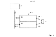
本監視方法は、導入部で述べたように、エレベータ装置に特に適している。図1は、本監視方法を実行するよう技術的に適合された本発明の安全システム10の一実施形態を示す。安全システム10は、制御部11と、少なくとも1つのバス接続部13とを有している。制御部11とバス接続部13との間の通信は、バス12を介して行われる。これにより、バス接続部13と制御部11との間でバスを介して双方向にデータを送ることができる。バス接続部13自体は、受信部14と、送信部15と、安全要素16とを備える。受信部14と送信部15は、前者がデフォルト信号を制御部11から受信し、後者が状態データを制御部11の信号として提供するようにそれぞれ設計されている。
This monitoring method is particularly suitable for an elevator apparatus as described in the introduction section. FIG. 1 shows one embodiment of a
制御部11と、バス12と、少なくとも1つのバス接続部13とはバス系を構成している。このバス系内では、各バス接続部13がそれぞれ固有のアドレスを有している。制御部11とバス接続部13との間の通信は、このアドレスを用いて確立される。
The
制御部11はデジタルのデフォルト信号をバス12を介して受信部14に送る。その場合の制御部は、特定のバス接続部13をアドレス指定して、デフォルト信号をその受信部14に伝達する。受信部14は、このデフォルト信号を受信して、デフォルト信号に対応し安全要素16に作用するアナログ信号を生成する。アナログ信号の作用は矢印16.1で示されている。アナログ信号は、規定の電圧、電流強度や周波数であってもよい。
The
安全要素16は安全関連要素の状態を示す。したがって、安全要素16は、例えば、扉接点、ロック接点、緩衝器接点、フラップ接点、センサ、アクチュエータ、走行スイッチ、非常停止スイッチとして利用することができる。ここで、安全要素16は、閉じた安全要素16が安全な状態を表し、開いた安全要素16がエレベータ装置に危険な状態があり得ることを表すように設計される。
安全要素16が閉じているときは、安全要素16の後段の送信部15が、到達したアナログ信号を測定する。この測定工程は矢印16.2で表されている。測定後、送信部15は測定されたアナログ信号をデジタル信号に変換する。最後に、送信部15は制御部11向けのデジタル信号を生成する。
When the
通常運転時には、制御部11は、電流値、電圧値または周波数値のデフォルト信号を、選択可能なバス接続部13に対してそのバス接続部13のアドレスの記述とデジタル形式の電流値、電圧値または周波数値とからなる命令文を用いて送信する。このデフォルト信号は所定の時間間隔で繰り返される。すなわち、制御部11は新たな電流値、電圧値または周波数値をバス接続部13に送信する。この新たな値は前回の値と異なっていることが好ましい。この時間間隔の間に、受信部がデフォルト信号に応じて特定のアナログ信号を生成する。安全要素が閉じていれば、送信部15がこのアナログ信号を測定し、その測定値をデジタル信号として生成する。上述の時間間隔のサイクルレートで、制御部11がバス接続部13の送信部15のアドレスを指定し、デジタル信号として生成された電流値、電圧値または周波数値のデータを読み取り機能によって取得する。
During normal operation, the
そのようなデフォルト問い合わせサイクルの時間間隔は、原則として自由に設定可能であり、主にバス接続部構成要素の信頼性に依存する。この時間間隔は数秒間であることが好ましい。信頼性が高い場合は、100秒間以上の時間間隔が設定されてもよい。 The time interval of such a default inquiry cycle can be freely set in principle and mainly depends on the reliability of the bus connection component. This time interval is preferably several seconds. When the reliability is high, a time interval of 100 seconds or more may be set.
制御部11は、この方法を一連のバス接続部13の全てに対して実行し、その共振を点検する。すなわち、デフォルト信号と、各送信部15によって提供されたデジタル信号とが制御部11によって比較される。デフォルト信号が、生成されたデジタル信号と一致した場合は、制御部は受信部14および送信部15が正確に機能していると認識する。
The
送信部15が0mAの電流、0mVの電圧、または0Hzの周波数を測定した場合は、異常電流、異常電圧、または異常周波数である。これは、開いた安全要素、すなわち、例えば、開いたケージ扉や昇降路扉の状態に相当する。ここで、例えば、異常電流が送信部15によって測定された場合、送信部15は自動的に送信値を制御部11に送る。バス接続部13の固有のアドレスのおかげで、制御部11は正確に異常個所を特定することができる。制御部11は、任意で、異常状態を解消するための、あるいはエレベータを安全運転モードに移行させるための手段をとる。この運転モードは、特に、エレベータの残った能力をエレベータケージの安全走行の範囲内に維持すること、閉じ込められた乗員を脱出させること、非常停止、または最終的には、閉じ込められた乗員を解放させたり、および/または制御部によっては取り除くことができない異常を解消したりするように保守サービス担当者に通知することを含む。
When the
バス接続部13の安全運転は、主に受信部14および送信部15の機能性に依存する。受信部14および送信部15は各デフォルト問い合わせサイクルの通常運転時にその機能性に関して既に検査されているので、異常発生時の送信部15の自動送信動作を点検するために、バス接続部13は別の検査を必要とする。
The safe operation of the
この別の検査では、開放状態の安全要素16がシミュレートされる。制御部11は、0mA、0mVまたは0Hzのデフォルト信号が特定のバス接続部13に送られるようにして、開放状態の安全要素16をシミュレートする。この場合には、このようにゼロデフォルト検査が関係してくる。バス接続部13が異常なく機能していれば、バス接続部13またはその送信部15は自動的に制御部11に報告を行うはずである。この検査は、安全要素16が開放状態の場合にはいつでも、バス接続部13が制御部11へ自動的にデジタル信号を送信することを保証する。
In this further inspection, the
この検査はバス接続部13毎に適時繰返し実行される。この検査中、制御部11は、検査されるバス接続部13の安全要素16の状態に関する真のデータを認識できないので、検査時間はできる限り短くされるとともに、検査は必要がある場合にのみ実行される。この場合、検査時間はバス12によるデータ伝送レートに大きく依存し、通常は50から100ミリ秒になる。ゼロデフォルト検査の頻度は、主に、使用される送信部15の信頼性に合わせられる。送信部15の信頼性が高いほどエレベータの安全運転が保証されるため、この検査が行なわれる必要回数が少なくなる。
This inspection is repeatedly performed at appropriate times for each
通常、ゼロデフォルト検査は少なくとも1日に1回実行される。しかし、この検査は分単位や時間単位で繰り返されてもよい。 Usually, the zero default check is performed at least once a day. However, this inspection may be repeated in minutes or hours.
図2は本発明の安全システム10の第2の実施形態を示す。図1の安全システム10とは異なり、安全要素16が冗長設計からなっている。したがって、各バス接続部13は少なくとも2つの安全要素16.a、16.b、16.nを有している。図2では、例えば、3つの安全要素16.a、16.b、16.nがエレベータの1つの安全関連要素の状態を監視する。この場合、各安全要素16.a、16.b、16.nは、制御部11のデフォルト信号に応じてアナログ信号に基づいて安全要素16.a、16.b、16.nに作用する受信部14の個別の出力16.1.a、16.1.b、16.1.nに接続されることが好ましい。これらの信号は同じ値であってもよいし、それぞれ異なる値であってもよい。接点16.a、16.b、16.nが閉じていれば、送信部15は個別の入力16.2.a、16.2.b、16.2.nごとに到達したアナログ信号を測定する。通常運転時には、送信部15は、アナログの測定値を、定期的にバス接続部13に問い合わせを行う制御部11がデジタル信号として利用できるようにする。入力16.2.a、16.2.b、16.2.nでアナログゼロ信号が測定された場合は、送信部15は自動的にそれを制御部11に報告する。
FIG. 2 shows a second embodiment of the
本実施形態の利点は、確実ではないがより有利な安全要素16.a、16.b、16.nも利用することができるという点である。エレベータの安全状態監視はその冗長設計によって保証される。
The advantage of this embodiment is the
本発明の安全システム10の第3の実施形態を図3に示す。本実施形態では、エレベータの複数の安全関連要素の状態がバス接続部13によって検出される。各安全関連要素の状態は安全要素16.d、16.e、16.mによって検出される。安全要素16.d、16.e、16.mを1つのバス接続部13に集めることは、監視されるべき安全関連要素が互いに物理的に近接している場合、例えば、上方の隣接する昇降路扉同士の場合や、ケージ扉とそのエレベータケージに搭載されている警報ボタンの場合などに実現されることが好ましい。
A third embodiment of the
制御部11は、安全要素16.d、16.e、16.mごとにそれぞれ異なるデフォルト信号を受信部に送ることが好ましい。受信部14はデフォルト信号を対応するアナログ信号に変換し、個別の出力16.1.d、16.1.e、16.1.mによってそれぞれの安全要素16.d、16.e、16.nに作用する。安全要素16.d、16.e、16.mが閉じていれば、送信部15が安全要素ごとに個々の入力16.2.d、16.2.e、16.2.mで到達したアナログ信号を測定する。この場合においても、送信部の通常運転時に、測定されたアナログ値が、定期的にバス接続部13に問い合わせを行う制御部11のデジタル信号として提供される。送信部15は、どの入力16.2.d、16.2.e、16.2.mでアナログ信号が測定されたかに関する情報も提供することが好ましい。入力16.2.d、16.2.e、16.2.mでアナログゼロ信号が測定された場合は、個別の入力16.2.d、16.2.e、16.2.mのおかげで故障源を特定することができる。
The
本実施形態の利点は、必要なバス接続部13の数が低減され、それによってコスト削減を実現できることである。
The advantage of this embodiment is that the number of required
図2および図3に示す実施例が組み合わされてもよい。すなわち、エレベータの複数の安全関連要素の状態がそれぞれの冗長安全要素16によって検出されるように、バス接続部13が設計されてもよい。
The embodiments shown in FIGS. 2 and 3 may be combined. That is, the
図2および図3に示すバス接続部13は、その共振に関して各デフォルト問い合わせサイクルの通常運転時のみならず、ゼロデフォルト信号によっても検査される。この検査は、各安全要素16.a、16.b、16.n;16.b、16.e、16.mごとに個別に実行されることが好ましい。これにより、受信部14の全ての出力および送信部15の全ての入力の機能性が個別に同時に検査される。
The
Claims (16)
Applications Claiming Priority (2)
| Application Number | Priority Date | Filing Date | Title |
|---|---|---|---|
| EP07112651 | 2007-07-17 | ||
| PCT/EP2008/058721 WO2009010410A1 (en) | 2007-07-17 | 2008-07-04 | Method for monitoring a lift system |
Publications (1)
| Publication Number | Publication Date |
|---|---|
| JP2011502908A true JP2011502908A (en) | 2011-01-27 |
Family
ID=38984174
Family Applications (1)
| Application Number | Title | Priority Date | Filing Date |
|---|---|---|---|
| JP2010516454A Pending JP2011502908A (en) | 2007-07-17 | 2008-07-04 | Elevator equipment monitoring method |
Country Status (14)
| Country | Link |
|---|---|
| US (1) | US8443944B2 (en) |
| EP (1) | EP2167413B1 (en) |
| JP (1) | JP2011502908A (en) |
| KR (1) | KR20100043185A (en) |
| CN (1) | CN101754920B (en) |
| AU (1) | AU2008277777B2 (en) |
| BR (1) | BRPI0814107A2 (en) |
| ES (1) | ES2400928T3 (en) |
| HK (1) | HK1145485A1 (en) |
| MX (1) | MX2010000566A (en) |
| MY (1) | MY159057A (en) |
| PL (1) | PL2167413T3 (en) |
| RU (1) | RU2482050C2 (en) |
| WO (1) | WO2009010410A1 (en) |
Families Citing this family (12)
| Publication number | Priority date | Publication date | Assignee | Title |
|---|---|---|---|---|
| EP2401221B1 (en) * | 2009-02-25 | 2013-07-31 | Inventio AG | Lift with a monitoring system |
| BR112013019511B1 (en) * | 2011-08-11 | 2021-04-20 | Inventio Ag | method and device for checking the functional capacity of at least one safety element of a safety circuit in a lifting installation |
| EP2607286A1 (en) | 2011-12-19 | 2013-06-26 | Inventio AG | Test method of an elevator system and a monitoring device for performing the test method |
| SG2014008825A (en) * | 2011-08-11 | 2014-04-28 | Inventio Ag | Test method for an elevator system and a monitoring device for carrying out the test method |
| AU2014339263B2 (en) * | 2013-10-23 | 2017-08-03 | Inventio Ag | Safety system for a lift, lift system and method for operating such a safety system |
| WO2015090809A1 (en) * | 2013-12-18 | 2015-06-25 | Inventio Ag | Safety system for an elevator system |
| EP2930134B1 (en) | 2014-04-09 | 2018-05-30 | Kone Corporation | Safety system and method for testing safety critical components in an elevator system |
| BR112017010771B1 (en) * | 2014-12-10 | 2022-02-22 | Inventio Ag | elevator system |
| US10549948B2 (en) * | 2014-12-18 | 2020-02-04 | Inventio Ag | Method for operating an electronic safety system with temporary participants |
| ES2722432T3 (en) * | 2014-12-18 | 2019-08-12 | Inventio Ag | Procedure for the operation of an electronic security system with temporary participants |
| ES2783349T3 (en) | 2015-12-21 | 2020-09-17 | Inventio Ag | Monitoring device for a people transport facility, test method and people transport facility |
| US10745244B2 (en) | 2017-04-03 | 2020-08-18 | Otis Elevator Company | Method of automated testing for an elevator safety brake system and elevator brake testing system |
Citations (6)
| Publication number | Priority date | Publication date | Assignee | Title |
|---|---|---|---|---|
| JPH02233486A (en) * | 1989-02-28 | 1990-09-17 | Otis Elevator Co | Cable breakage detector for elevator |
| JPH04243784A (en) * | 1991-01-28 | 1992-08-31 | Mitsubishi Electric Corp | Signal transmission device for elevator |
| JP2005502567A (en) * | 2001-09-18 | 2005-01-27 | インベンテイオ・アクテイエンゲゼルシヤフト | Safety circuit for elevator doors |
| JP2005126240A (en) * | 2003-10-20 | 2005-05-19 | Inventio Ag | Safety system for elevator installation and method of operating elevator installation with safety system |
| WO2007026416A1 (en) * | 2005-08-31 | 2007-03-08 | Mitsubishi Denki Kabushiki Kaisha | Control system for elevator |
| JP2007506625A (en) * | 2003-06-30 | 2007-03-22 | インベンテイオ・アクテイエンゲゼルシヤフト | Safety system for elevator structures |
Family Cites Families (12)
| Publication number | Priority date | Publication date | Assignee | Title |
|---|---|---|---|---|
| AU7624974A (en) * | 1973-12-20 | 1976-06-10 | Production Eng Co Ltd | Electric fences |
| DE9015495U1 (en) * | 1990-11-12 | 1992-01-02 | Technischer Ueberwachungs-Verein Bayern E.V., 8000 Muenchen, De | |
| US5387769A (en) * | 1993-06-01 | 1995-02-07 | Otis Elevator Company | Local area network between an elevator system building controller, group controller and car controller, using redundant communication links |
| US6173814B1 (en) * | 1999-03-04 | 2001-01-16 | Otis Elevator Company | Electronic safety system for elevators having a dual redundant safety bus |
| RU15716U1 (en) * | 2000-07-28 | 2000-11-10 | Горохов Сергей Львович | DEVICE FOR ANALYSIS OF THE STATUS OF DOOR LIFT DOORS |
| CN1132776C (en) * | 2000-07-29 | 2003-12-31 | 肖明欢 | Device and method for monitoring opening or closing of elevator door lock |
| US6267219B1 (en) * | 2000-08-11 | 2001-07-31 | Otis Elevator Company | Electronic safety system for escalators |
| US6467585B1 (en) * | 2001-07-05 | 2002-10-22 | Otis Elevator Company | Wireless safety chain for elevator system |
| US7334665B2 (en) * | 2004-03-02 | 2008-02-26 | Thyssenkrupp Elevator Capital Corporation | Interlock wiring communication system for elevators |
| WO2008155164A1 (en) * | 2007-06-18 | 2008-12-24 | Inventio Ag | Device and method for controlling a brake device |
| EP2022742B1 (en) * | 2007-08-07 | 2014-06-25 | ThyssenKrupp Elevator AG | Lift system |
| KR20170030662A (en) * | 2008-09-19 | 2017-03-17 | 인벤티오 아게 | Method for operating a lift system, call input device, lift system comprising a call input device of this type and method for retrofitting a lift system with a call input device of this type |
-
2008
- 2008-07-04 WO PCT/EP2008/058721 patent/WO2009010410A1/en active Application Filing
- 2008-07-04 JP JP2010516454A patent/JP2011502908A/en active Pending
- 2008-07-04 BR BRPI0814107-0A2A patent/BRPI0814107A2/en active IP Right Grant
- 2008-07-04 PL PL08774798T patent/PL2167413T3/en unknown
- 2008-07-04 MX MX2010000566A patent/MX2010000566A/en active IP Right Grant
- 2008-07-04 MY MYPI2010000192A patent/MY159057A/en unknown
- 2008-07-04 US US12/669,322 patent/US8443944B2/en active Active
- 2008-07-04 ES ES08774798T patent/ES2400928T3/en active Active
- 2008-07-04 RU RU2010105545/11A patent/RU2482050C2/en active
- 2008-07-04 EP EP08774798A patent/EP2167413B1/en active Active
- 2008-07-04 AU AU2008277777A patent/AU2008277777B2/en active Active
- 2008-07-04 CN CN2008800249407A patent/CN101754920B/en active Active
- 2008-07-04 KR KR1020107000933A patent/KR20100043185A/en not_active IP Right Cessation
-
2010
- 2010-12-15 HK HK10111679.3A patent/HK1145485A1/en unknown
Patent Citations (6)
| Publication number | Priority date | Publication date | Assignee | Title |
|---|---|---|---|---|
| JPH02233486A (en) * | 1989-02-28 | 1990-09-17 | Otis Elevator Co | Cable breakage detector for elevator |
| JPH04243784A (en) * | 1991-01-28 | 1992-08-31 | Mitsubishi Electric Corp | Signal transmission device for elevator |
| JP2005502567A (en) * | 2001-09-18 | 2005-01-27 | インベンテイオ・アクテイエンゲゼルシヤフト | Safety circuit for elevator doors |
| JP2007506625A (en) * | 2003-06-30 | 2007-03-22 | インベンテイオ・アクテイエンゲゼルシヤフト | Safety system for elevator structures |
| JP2005126240A (en) * | 2003-10-20 | 2005-05-19 | Inventio Ag | Safety system for elevator installation and method of operating elevator installation with safety system |
| WO2007026416A1 (en) * | 2005-08-31 | 2007-03-08 | Mitsubishi Denki Kabushiki Kaisha | Control system for elevator |
Also Published As
| Publication number | Publication date |
|---|---|
| CN101754920B (en) | 2013-07-03 |
| KR20100043185A (en) | 2010-04-28 |
| US20120273307A1 (en) | 2012-11-01 |
| BRPI0814107A2 (en) | 2015-02-03 |
| MX2010000566A (en) | 2010-03-08 |
| AU2008277777B2 (en) | 2014-01-16 |
| HK1145485A1 (en) | 2011-04-21 |
| EP2167413A1 (en) | 2010-03-31 |
| EP2167413B1 (en) | 2012-12-05 |
| US8443944B2 (en) | 2013-05-21 |
| PL2167413T3 (en) | 2013-05-31 |
| RU2482050C2 (en) | 2013-05-20 |
| MY159057A (en) | 2016-12-15 |
| RU2010105545A (en) | 2011-08-27 |
| CN101754920A (en) | 2010-06-23 |
| ES2400928T3 (en) | 2013-04-15 |
| WO2009010410A1 (en) | 2009-01-22 |
| AU2008277777A1 (en) | 2009-01-22 |
Similar Documents
| Publication | Publication Date | Title |
|---|---|---|
| JP2011502908A (en) | Elevator equipment monitoring method | |
| CA2844522C (en) | Test method for an elevator system and a monitoring device for carrying out the test method | |
| JP4601827B2 (en) | Elevator safety system | |
| JP4647599B2 (en) | Safety system for elevator structures | |
| JP6088977B2 (en) | Method for identifying malfunction of elevator safety circuit and elevator safety circuit | |
| EP3403970B1 (en) | A method and system for generating maintenance data of an elevator door system | |
| AU2016376176B2 (en) | Monitoring device for a passenger transport system, testing method and passenger transport system | |
| CN111137773B (en) | Method and system for detecting faults in an elevator system | |
| CN112938681B (en) | Electronic test node for automatic inspection of a safety chain | |
| CN114734438A (en) | Fault diagnosis method and system for robot joint | |
| KR101856866B1 (en) | Optical safety sensor diagnosis system for elevator door | |
| CA2707389C (en) | Method for monitoring a lift installation | |
| KR20020032098A (en) | remote control system for elevator | |
| KR200247837Y1 (en) | Apparatus for faults sensing of interlock switch and controlling for opening and closing of doors engine of a railway vehicle | |
| NZ620402B2 (en) | Test method for an elevator system and a monitoring device for carrying out the test method |
Legal Events
| Date | Code | Title | Description |
|---|---|---|---|
| A621 | Written request for application examination |
Free format text: JAPANESE INTERMEDIATE CODE: A621 Effective date: 20110628 |
|
| A977 | Report on retrieval |
Free format text: JAPANESE INTERMEDIATE CODE: A971007 Effective date: 20121109 |
|
| A131 | Notification of reasons for refusal |
Free format text: JAPANESE INTERMEDIATE CODE: A131 Effective date: 20121204 |
|
| RD02 | Notification of acceptance of power of attorney |
Free format text: JAPANESE INTERMEDIATE CODE: A7422 Effective date: 20130207 |
|
| A02 | Decision of refusal |
Free format text: JAPANESE INTERMEDIATE CODE: A02 Effective date: 20130507 |