JP2011502222A - Method and apparatus for heating a catalyst disposed in an exhaust gas region of an internal combustion engine - Google Patents
Method and apparatus for heating a catalyst disposed in an exhaust gas region of an internal combustion engine Download PDFInfo
- Publication number
- JP2011502222A JP2011502222A JP2009543472A JP2009543472A JP2011502222A JP 2011502222 A JP2011502222 A JP 2011502222A JP 2009543472 A JP2009543472 A JP 2009543472A JP 2009543472 A JP2009543472 A JP 2009543472A JP 2011502222 A JP2011502222 A JP 2011502222A
- Authority
- JP
- Japan
- Prior art keywords
- exhaust gas
- temperature
- internal combustion
- combustion engine
- catalyst
- Prior art date
- Legal status (The legal status is an assumption and is not a legal conclusion. Google has not performed a legal analysis and makes no representation as to the accuracy of the status listed.)
- Pending
Links
Images


Classifications
-
- F—MECHANICAL ENGINEERING; LIGHTING; HEATING; WEAPONS; BLASTING
- F02—COMBUSTION ENGINES; HOT-GAS OR COMBUSTION-PRODUCT ENGINE PLANTS
- F02D—CONTROLLING COMBUSTION ENGINES
- F02D41/00—Electrical control of supply of combustible mixture or its constituents
- F02D41/02—Circuit arrangements for generating control signals
- F02D41/021—Introducing corrections for particular conditions exterior to the engine
- F02D41/0235—Introducing corrections for particular conditions exterior to the engine in relation with the state of the exhaust gas treating apparatus
- F02D41/024—Introducing corrections for particular conditions exterior to the engine in relation with the state of the exhaust gas treating apparatus to increase temperature of the exhaust gas treating apparatus
- F02D41/0245—Introducing corrections for particular conditions exterior to the engine in relation with the state of the exhaust gas treating apparatus to increase temperature of the exhaust gas treating apparatus by increasing temperature of the exhaust gas leaving the engine
-
- F—MECHANICAL ENGINEERING; LIGHTING; HEATING; WEAPONS; BLASTING
- F02—COMBUSTION ENGINES; HOT-GAS OR COMBUSTION-PRODUCT ENGINE PLANTS
- F02D—CONTROLLING COMBUSTION ENGINES
- F02D41/00—Electrical control of supply of combustible mixture or its constituents
- F02D41/02—Circuit arrangements for generating control signals
- F02D41/021—Introducing corrections for particular conditions exterior to the engine
- F02D41/0235—Introducing corrections for particular conditions exterior to the engine in relation with the state of the exhaust gas treating apparatus
- F02D41/024—Introducing corrections for particular conditions exterior to the engine in relation with the state of the exhaust gas treating apparatus to increase temperature of the exhaust gas treating apparatus
- F02D41/025—Introducing corrections for particular conditions exterior to the engine in relation with the state of the exhaust gas treating apparatus to increase temperature of the exhaust gas treating apparatus by changing the composition of the exhaust gas, e.g. for exothermic reaction on exhaust gas treating apparatus
-
- F—MECHANICAL ENGINEERING; LIGHTING; HEATING; WEAPONS; BLASTING
- F02—COMBUSTION ENGINES; HOT-GAS OR COMBUSTION-PRODUCT ENGINE PLANTS
- F02D—CONTROLLING COMBUSTION ENGINES
- F02D41/00—Electrical control of supply of combustible mixture or its constituents
- F02D41/02—Circuit arrangements for generating control signals
- F02D41/021—Introducing corrections for particular conditions exterior to the engine
- F02D41/0235—Introducing corrections for particular conditions exterior to the engine in relation with the state of the exhaust gas treating apparatus
- F02D41/024—Introducing corrections for particular conditions exterior to the engine in relation with the state of the exhaust gas treating apparatus to increase temperature of the exhaust gas treating apparatus
- F02D41/0255—Introducing corrections for particular conditions exterior to the engine in relation with the state of the exhaust gas treating apparatus to increase temperature of the exhaust gas treating apparatus to accelerate the warming-up of the exhaust gas treating apparatus at engine start
-
- F—MECHANICAL ENGINEERING; LIGHTING; HEATING; WEAPONS; BLASTING
- F02—COMBUSTION ENGINES; HOT-GAS OR COMBUSTION-PRODUCT ENGINE PLANTS
- F02D—CONTROLLING COMBUSTION ENGINES
- F02D41/00—Electrical control of supply of combustible mixture or its constituents
- F02D41/30—Controlling fuel injection
- F02D41/38—Controlling fuel injection of the high pressure type
- F02D41/40—Controlling fuel injection of the high pressure type with means for controlling injection timing or duration
- F02D41/402—Multiple injections
- F02D41/405—Multiple injections with post injections
-
- F—MECHANICAL ENGINEERING; LIGHTING; HEATING; WEAPONS; BLASTING
- F02—COMBUSTION ENGINES; HOT-GAS OR COMBUSTION-PRODUCT ENGINE PLANTS
- F02D—CONTROLLING COMBUSTION ENGINES
- F02D2200/00—Input parameters for engine control
- F02D2200/02—Input parameters for engine control the parameters being related to the engine
- F02D2200/08—Exhaust gas treatment apparatus parameters
- F02D2200/0802—Temperature of the exhaust gas treatment apparatus
- F02D2200/0804—Estimation of the temperature of the exhaust gas treatment apparatus
-
- Y—GENERAL TAGGING OF NEW TECHNOLOGICAL DEVELOPMENTS; GENERAL TAGGING OF CROSS-SECTIONAL TECHNOLOGIES SPANNING OVER SEVERAL SECTIONS OF THE IPC; TECHNICAL SUBJECTS COVERED BY FORMER USPC CROSS-REFERENCE ART COLLECTIONS [XRACs] AND DIGESTS
- Y02—TECHNOLOGIES OR APPLICATIONS FOR MITIGATION OR ADAPTATION AGAINST CLIMATE CHANGE
- Y02T—CLIMATE CHANGE MITIGATION TECHNOLOGIES RELATED TO TRANSPORTATION
- Y02T10/00—Road transport of goods or passengers
- Y02T10/10—Internal combustion engine [ICE] based vehicles
- Y02T10/12—Improving ICE efficiencies
-
- Y—GENERAL TAGGING OF NEW TECHNOLOGICAL DEVELOPMENTS; GENERAL TAGGING OF CROSS-SECTIONAL TECHNOLOGIES SPANNING OVER SEVERAL SECTIONS OF THE IPC; TECHNICAL SUBJECTS COVERED BY FORMER USPC CROSS-REFERENCE ART COLLECTIONS [XRACs] AND DIGESTS
- Y02—TECHNOLOGIES OR APPLICATIONS FOR MITIGATION OR ADAPTATION AGAINST CLIMATE CHANGE
- Y02T—CLIMATE CHANGE MITIGATION TECHNOLOGIES RELATED TO TRANSPORTATION
- Y02T10/00—Road transport of goods or passengers
- Y02T10/10—Internal combustion engine [ICE] based vehicles
- Y02T10/40—Engine management systems
Abstract
Description
本発明は、独立の請求項の上位概念に基づく、特に内燃機関の、燃焼プロセスの排気ガス領域内に配置された触媒の加熱方法及びこの方法を実施するための装置に関する。 The invention relates to a method for heating a catalyst arranged in the exhaust gas region of a combustion process, in particular an internal combustion engine, based on the superordinate concept of the independent claims, and an apparatus for carrying out this method.
内燃機関は、燃料直接噴射によって運転され、その際触媒の加熱のために点火角度遅延並びに点火の前の燃料噴射の少なくとも二回の燃料部分噴射への分割が行われる。この措置によって生じるトルク損失は引き上げられたシリンダ充填効率によって補償される。未だ変換することができない冷たい触媒の下では、内燃機関の少ない排気ガス未処理排出を達成するために、場合によっては空気過剰率をラムダ>1に定めること、即ち、内燃機関を希薄な燃料/空気混合気で運転することが行われる。 The internal combustion engine is operated by direct fuel injection, in which the ignition angle is delayed and the fuel injection before ignition is divided into at least two partial fuel injections for heating the catalyst. The torque loss caused by this measure is compensated by the increased cylinder filling efficiency. Under a cold catalyst that still cannot be converted, in order to achieve low exhaust emissions of the internal combustion engine, in some cases, the excess air ratio is set to lambda> 1, i.e. the internal combustion engine is operated with lean fuel / Operation with an air-fuel mixture is performed.
その様な方法及びその様な制御装置は既に量産の中で用いられている。既知の方法によれば、例えば内燃機関のスタート過程の後の冷たい触媒の下では、内燃機関の出力或いはスタート後の段階で場合によっては引き上げられる例えば1,200/minのアイドリング回転数を変えること無しに、排気ガス中にできるだけ大きな熱量を発生させるという方策が行われる。 Such a method and such a control device are already used in mass production. According to the known method, for example, under a cold catalyst after the start process of the internal combustion engine, changing the output of the internal combustion engine or the idling speed, for example 1200 / min, which may be increased at the stage after the start. Instead, measures are taken to generate as much heat as possible in the exhaust gas.
これは、そこで用いられている方法の場合、燃料量の第一の部分を吸気行程の中で、また燃料量の第二の部分を圧縮行程の中で噴射するということによって達成される。その結果、燃焼室内に、第二の部分の噴射から生じる比較的過濃で、従って着火性の良い燃料/空気混合気の領域を点火プラグの近くに持つ、成層化された燃料分布が得られる。内燃機関のこの様な運転は、均質分割運転(Homogen-Split-Betrieb)と呼ぶことができ、その際“分割”というのは噴射の分割と関連している。 This is achieved by injecting a first part of the fuel quantity in the intake stroke and a second part of the fuel quantity in the compression stroke in the method used there. The result is a stratified fuel distribution in the combustion chamber with a relatively rich and thus ignitable fuel / air mixture region near the spark plug resulting from the injection of the second part. . Such operation of the internal combustion engine can be referred to as homogenous split operation (Homogen-Split-Betrieb), where “split” is related to splitting of the injection.
充填気成層は、安定した回転数特性とコントロール可能な排気ガス未処理排出の下で、OT(OT=上死点)の後10〜30゜の範囲内の非常に遅い点火時期を可能にする。遅い点火時期は、比較的悪い点火角度効率をもたらす。ここで、点火効率とは、遅い点火時期の下で生成されるトルクと最適点火時期の下で生成されるトルクとの比であると理解されるものとする。悪い点火時期効率から生じるトルク損失は、内燃機関の燃焼室充填効率の引き上げによって補償される。実現された点火角度の下では、基準条件の下で可能となる最大充填効率の約75%の値までの燃焼室充填効率の引き上げが行われる。これによって、全体として比較的大きな排気ガス量が生まれ、その温度は点火角度効率が悪いために比較的高いので、排気ガス領域内に最大熱流(エンタルピー流)が生まれる。 Filled air stratification allows very late ignition timing within 10-30 ° after OT (OT = top dead center) under stable engine speed and controllable exhaust gas untreated emissions . Slow ignition timing results in relatively poor ignition angle efficiency. Here, the ignition efficiency is understood to be the ratio of the torque generated under the slow ignition timing and the torque generated under the optimal ignition timing. Torque loss resulting from poor ignition timing efficiency is compensated by increasing the combustion chamber filling efficiency of the internal combustion engine. Under the realized ignition angle, the combustion chamber charging efficiency is increased to a value of about 75% of the maximum charging efficiency possible under the reference conditions. As a result, a relatively large amount of exhaust gas is generated as a whole, and the temperature is relatively high due to poor ignition angle efficiency, so that a maximum heat flow (enthalpy flow) is generated in the exhaust gas region.
エンタルピー流のこの最大化によって加熱する場合には、排気ガス領域が排気弁から触媒まで完全に加熱されなければならない。これ等の構成部分の熱容量は、とりわけ排気ガスターボチャージャー付きの内燃機関の場合、触媒の手前で過度に高い熱損失をもたらし、触媒の効果的な加熱を困難にする。排気ガスターボチャージャー付きの内燃機関の場合には更に、ターボチャージャーのタービンの手前の排気ガスの流路の中にある排気ガスマニホルドが、排気ガスエンタルピーを最大化させると、非常に急速にそれ以上加熱するとその破壊をもたらす恐れのある温度まで加熱されてしまうということが問題となる。このことが、触媒の加熱のために望ましい排気ガスエンタルピーの最大化を制約している。 When heating by this maximal enthalpy flow, the exhaust gas region must be fully heated from the exhaust valve to the catalyst. The heat capacity of these components, especially in the case of an internal combustion engine with an exhaust gas turbocharger, results in an excessively high heat loss before the catalyst, making it difficult to effectively heat the catalyst. Furthermore, in the case of an internal combustion engine with an exhaust gas turbocharger, if the exhaust gas manifold in the exhaust gas flow path in front of the turbocharger turbine maximizes the exhaust gas enthalpy, it will increase more rapidly. When heated, the problem is that it is heated to a temperature that may cause its destruction. This constrains the maximization of the desired exhaust gas enthalpy for catalyst heating.
先に述べられた内燃機関の均質分割運転は、燃料噴射時期と点火時期のコンスタントなタイミングでのアフタースタート段階の中で採用することができる。従来の内燃機関の制御装置では、スタート操作の後のアフタースタート段階は、内燃機関の回転数がスターター回転数と内燃機関のアイドリング回転数の間にある回転数閾値をオーバーし且つ予め定められている通常20〜30秒の時間間隔の間持続された時に始まる。この時間間隔の間に、内燃機関の近くに配置された前置触媒が通常、有害物質の変換、とりわけ水酸化物の変換が感知可能に開始される作動温度(ライトオフ温度)に到達する。通常の定義によれば、このライトオフ温度とは、触媒の手前に現れる一酸化炭素(CO)や炭化水素(HC)などの望ましくない排気ガス成分の50%が水や二酸化炭素などの無害な排気ガス成分へ変換される温度である。 The above-described homogeneous division operation of the internal combustion engine can be employed in the after-start stage at a constant timing of the fuel injection timing and the ignition timing. In the conventional internal combustion engine control device, in the after-start stage after the start operation, the rotational speed of the internal combustion engine exceeds a rotational speed threshold that is between the starter rotational speed and the idling rotational speed of the internal combustion engine, and is determined in advance. It begins when it lasts for a time interval of typically 20-30 seconds. During this time interval, the pre-catalyst located near the internal combustion engine usually reaches an operating temperature (light-off temperature) at which the conversion of harmful substances, in particular the conversion of hydroxides, is sensibly started. According to the usual definition, this light-off temperature means that 50% of undesirable exhaust gas components such as carbon monoxide (CO) and hydrocarbon (HC) appearing in front of the catalyst are harmless such as water and carbon dioxide. This is the temperature converted to the exhaust gas component.
実際には、有害物質変換のパーセンテージは急激には上昇せず、むしろ緩やかに上昇して行く。前置触媒の中での有害物質変換の開始の後、前置触媒の後方で測定可能な炭化水素の濃度は、急速にゼロに近い値へ向かって低下する。テストによれば、前置触媒の後方での炭化水素濃度の低下は、前置触媒の中央領域内でのライトオフ温度の到達と相関関係にある。従って、内燃機関のコールドスタートの後或いは例えば惰行(オーバーラン)時燃料カットオフ(燃料供給無しの内燃機関の運転)の後に、環境中へ排出される炭化水素の量は触媒の作動温度の到達のために必要な時間間隔に大きく依存している。 In practice, the percentage of hazardous substance conversion does not increase rapidly but rather increases slowly. After the start of toxic substance conversion in the pre-catalyst, the concentration of hydrocarbons measurable behind the pre-catalyst rapidly decreases towards a value close to zero. According to tests, the decrease in hydrocarbon concentration behind the pre-catalyst correlates with the arrival of the light-off temperature in the central region of the pre-catalyst. Thus, after a cold start of the internal combustion engine or after, for example, a fuel cut-off (operation of the internal combustion engine without fuel supply) during overrun, the amount of hydrocarbons discharged into the environment will reach the operating temperature of the catalyst. Depends heavily on the time interval needed for.
以上の様な背景の下で、本発明は触媒の迅速な加熱を可能にする方法及びこの方法の実施のための装置を提供することを課題としている。 Under the background as described above, an object of the present invention is to provide a method enabling rapid heating of a catalyst and an apparatus for carrying out the method.
本発明によれば、触媒の温度に関する尺度が測定され、減少させるべき排気ガス成分の量が、触媒温度が予め定められている閾値をオーバーすると、内燃機関の制御装置への介入によって引き上げられる、ということが行われる。 According to the invention, a measure for the temperature of the catalyst is measured and the amount of exhaust gas component to be reduced is raised by intervention in the control device of the internal combustion engine when the catalyst temperature exceeds a predetermined threshold, That is done.
内燃機関が、未だ変換することのできない冷たい触媒の下では、希薄な燃料/空気混合気で運転されるということによって、可能最少限の例えば未燃焼炭化水素など排気ガス未処理排出物しか環境中へ排出されない。内燃機関のこの運転状態の間に触媒の加熱が内燃機関の効率の引き下げによって達成される。 An internal combustion engine is operated with a lean fuel / air mixture under a cold catalyst that still cannot be converted, so that only the smallest possible untreated exhaust gas emissions such as unburned hydrocarbons are in the environment. Is not discharged. During this operating state of the internal combustion engine, heating of the catalyst is achieved by reducing the efficiency of the internal combustion engine.
触媒温度の予め定められている温度閾値が到達された時に初めて、減少させるべき排気ガス成分の量が内燃機関の制御装置への介入によって引き上げられる。
ライトオフ温度に到達するまでの時間及びそれによって環境中へ放出される炭化水素の量は、この措置によって低減されるということが示された。この有利な効果は、触媒の中央領域内の温度は未だかなり低く、なお触媒の作動温度域の下側にあるにも係わらず、触媒の入口の最初の触媒コーティングを施された表面要素が、触媒の入口の温度が予め定められている閾値をオーバーすると、既に変換を開始するということに基づいていると考えられる。
Only when a predetermined temperature threshold of the catalyst temperature is reached, the amount of exhaust gas component to be reduced is raised by intervention in the control device of the internal combustion engine.
It has been shown that this measure reduces the time to reach the light-off temperature and thereby the amount of hydrocarbons released into the environment. This advantageous effect is that, even though the temperature in the central region of the catalyst is still quite low and still below the operating temperature range of the catalyst, It is considered that the conversion is already started when the temperature at the inlet of the catalyst exceeds a predetermined threshold.
排気ガス中に存在している酸素と組合された、減少させるべき排気ガス成分の引き上げられた供給によって、この表面要素の上で発熱反応が開始され、この反応がダイレクトで、直接的な、従って加速された触媒の加熱に寄与する。その際に行われる、例えば連続的に行われる、減少させるべき排気ガス成分の量の引き上げによって、触媒内で発生される熱の連続的増加が行われる。それによって、加速される触媒の最初の数センチメートルの加熱は、従来技術の場合(及び本発明でも温度閾値のオーバー前)に利用される、機関内での燃焼からの一定のエンタルピー流による加熱よりも遥かに効果的である。このことはとりわけ、エンタルピー流が、触媒の中へ入る前に、別の構成部分の加温による損失を受けるということに関係している。例えば、その様な別の構成部分には、排気ガスマニホルド、ターボチャージャー等がある。 The raised supply of exhaust gas components to be reduced combined with the oxygen present in the exhaust gas initiates an exothermic reaction on this surface element, which is direct and direct, thus Contributes to accelerated catalyst heating. The heat generated in the catalyst is continuously increased by increasing the amount of the exhaust gas component to be reduced, for example, continuously. Thereby, the first few centimeters of heating of the accelerated catalyst is heated by a constant enthalpy flow from combustion in the engine, which is utilized in the prior art case (and also before the temperature threshold is exceeded in the present invention). Is much more effective than This is inter alia related to the fact that the enthalpy stream suffers losses due to the warming of other components before entering the catalyst. For example, such other components include an exhaust gas manifold, a turbocharger, and the like.
本発明に基づく手法の重要なその他の利点として、未燃焼の、削減されるべき排気ガス成分の排出を削減する他に、窒素酸化物排出の削減もある。
本発明に基づく手法の有利な拡張例と実施例は添付の諸請求項から明らかとなる。
Another important advantage of the approach according to the invention is that in addition to reducing the emission of unburned exhaust gas components to be reduced, there is also a reduction in nitrogen oxide emissions.
Advantageous extensions and embodiments of the technique according to the invention will become apparent from the appended claims.
一実施例によれば、減少させるべき排気ガス成分の量は、その点火角度遅延の復帰によって達成される。
代わりの手法として或いは追加として、一実施例によれば、減少させるべき排気ガス成分の量は、燃料部分噴射の中で点火前の予め定められている燃料量の分割の変更によって達成される。
According to one embodiment, the amount of exhaust gas component to be reduced is achieved by returning the ignition angle delay.
As an alternative or in addition, according to one embodiment, the amount of exhaust gas component to be reduced is achieved by changing a predetermined fuel amount division prior to ignition in the fuel partial injection.
更に代わりの手法として或いは追加として、一実施例によれば、減少させるべき排気ガス成分の量は、空気過剰率ラムダを、より低い空気過剰率のスタートポイントと反対の側へ引き下げることによって達成される。 Further alternatively or additionally, according to one embodiment, the amount of exhaust gas component to be reduced is achieved by lowering the excess air lambda to the side opposite the lower excess air start point. The
更に代わりの手法として或いは追加として、燃焼の開始の後に少なくとも一回の燃料ポスト噴射を行うことができる。
とりわけ、少なくとも一回の燃料ポスト噴射を行う実施例の枠組みの中では、次の利点が生じる。排気ガスエンタルピーの最大化によって、その他の噴射によってドーズされる燃料量の準備と気化が顕著に改善されるので、燃料が液滴の形で触媒の中へ達すると云う確率が引き下げられる。遅延点火と高められた内燃機関充填効率によって排気ガスエンタルピーが引き上げられたとしても、追加としてドーズされた燃料量の気化によって再び引き下げられる。しかしながら、触媒の望ましい加熱という観点から見れば、この引き下げは、発熱反応による触媒のより効果的な加熱によって十二分に補償される。排気ガスターボチャージャー付きの内燃機関の場合には、排気ガスエンタルピーの最大化の際には、追加の燃料のドージング無しでも発生することのある過熱に対するマニホルドの保護という追加の利点をもたらす。この追加の、触媒前の最低温度と結び付いている噴射は、ここではターボチャージャーの手前の温度が低下し、これがマニホルドを保護するということ、及びそれでも触媒の加熱のために、少なくとも一回の燃料ポスト噴射無しの場合よりもより多いエネルギーが用意されるという、二重の効用を発揮する。
Further alternatively or additionally, at least one fuel post-injection can be performed after the start of combustion.
In particular, within the framework of an embodiment with at least one fuel post injection, the following advantages arise: Maximizing the exhaust gas enthalpy significantly improves the preparation and vaporization of the fuel dosed by the other injections, thereby reducing the probability that the fuel will reach the catalyst in the form of droplets. Even if the exhaust gas enthalpy is raised due to delayed ignition and increased internal combustion engine charging efficiency, it is again lowered by vaporization of the amount of fuel dosed. However, from the standpoint of desirable heating of the catalyst, this reduction is more than compensated for by more effective heating of the catalyst by an exothermic reaction. In the case of an internal combustion engine with an exhaust gas turbocharger, maximizing the exhaust gas enthalpy provides the additional advantage of protecting the manifold against overheating that may occur without additional fuel dosing. This additional injection associated with the minimum pre-catalyst temperature reduces the temperature in front of the turbocharger, which protects the manifold, and still at least one fuel to heat the catalyst. It has the dual effect of providing more energy than without post-injection.
この方法の実施のための本発明に基づく装置は先ず、この方法の実施のための手段を含んでいる特別に仕立てられた制御装置に関している。
この制御装置は、プロセスステップが制御装置プログラムとして格納されている、好ましくは少なくとも一つの電気的メモリを含んでいる。
The device according to the invention for the implementation of this method relates first to a specially tailored control device including means for carrying out this method.
The control device preferably includes at least one electrical memory in which process steps are stored as a control device program.
本発明に基づく制御装置プログラムは、それが制御装置で実行されると、本発明に基づく方法の全てのステップが実施されることを想定している。
機械読み取り可能な媒体に記録されたプログラムコードを備えた本発明に基づく制御装置プログラム製品は、プログラムが制御装置で実行されると、本発明に基づく方法を実施する。
The control device program according to the invention assumes that all steps of the method according to the invention are carried out when it is executed on the control device.
A control device program product according to the invention with program code recorded on a machine-readable medium implements the method according to the invention when the program is executed on the control device.
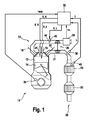
図1は内燃機関10を示しており、この内燃機関10は、詳しくはピストン14によって可動に密閉された少なくとも一つの燃焼室12を備えている。燃焼室12の燃料と空気から成る混合気による充填気は点火プラグ16によって点火され、次いで燃焼される。有利な実施態様では、内燃機関10は噴射制御燃焼法(strahlgefuhrte Brennverfahren)に合わせて最適化されている。燃焼法とは、燃焼室内での混合気形成とエネルギー変換の方法のことである。噴射制御燃焼法は、燃料が点火プラグの直接周辺に噴射され且つそこで気化される。この手法は、混合気を正しい時点に着火させるために、点火プラグ16と燃料噴射器の正確な位置決め並びに精確な噴射方向を必要とする。燃焼室12の充填気の交換は、ピストン14の運動に対して位相同期的に開閉されるガス交換弁18(吸気弁)及び20(排気弁)によって制御される。ガス交換弁18及び20の操作のための様々な手法は、当業者に委ねられており、見易くするために図1には詳しくは示されていない。吸気弁18が開かれ且つピストン14が下へ向かって動いている時、即ち吸気行程では、空気は吸気システム22から燃焼室12の中へ流入する。噴射器24を通じて燃料が燃焼室12内の空気の中へドーズされる。燃焼室充填気の燃焼から生じた排気ガスは排気弁20が開かれると排気ガスシステム26の中へ押し出されるが、その際この排気ガスシステムには少なくとも一つの触媒28が備えられており、この触媒は、少なくとも部分的には、触媒28が酸素と排気ガスの還元性の成分との酸化反応を触媒的に支援するように作られている。一般に、この排気ガスシステム26は、複数の触媒、例えばエンジンの近くに組み込まれた前置触媒、図示されている実施例では触媒28と、エンジンから遠くに配置された、例えば三元触媒或いはNOx吸蔵型触媒とすることのできる、もう一つの触媒30とを含んでいる。
FIG. 1 shows an
図1の実施態様では、内燃機関10は、マニホルド31と触媒28との間の排気ガスの流路の中に配置されたターボチャージャー29を備えている。既に述べられたように、その様な内燃機関では、マニホルドの保護と触媒28の加速された加熱との結び付きによって特別な利点が生まれる。しかしながら、本発明は、ターボチャージャーを備えた内燃機関に対する適用だけに限定されてはいないということが理解されるべきである。何故なら触媒28の加速された加熱の利点は、排気ガスターボチャージャー29を備えていない内燃機関10の場合にも生じるからである。
In the embodiment of FIG. 1, the
内燃機関10或いは内燃機関10の中での燃焼は制御装置32によって制御され、この制御装置はそのために、内燃機関10の運転パラメータが反映されている様々なセンサの信号を処理する。図1によれば、それ等の信号には、内燃機関10のクランクシャフトの角度位置 ゜KW、それによってピストン14の位置を測定する回転角度センサ34、内燃機関10の中へ流入するエアマスmLを測定するエアマス計36、及びオプションとして、排気ガス成分の濃度及び/又は排気ガスの温度Tを測定する複数の排気ガスセンサ38、40がある。
The
図1の実施態様では、排気ガスセンサ38は空気過剰率L(L=ラムダ)の尺度として排気ガス中の酸素濃度を測定するラムダセンサであり、それに対してセンサ40は排気ガス温度Tを測定する。図示されている実施例では、センサ40は触媒28の入口での排気ガス温度Tを測定する。空気過剰率ラムダは、周知のように、実際に利用できるエアマスを分子とし、一定の燃料量の理論的燃焼のために必要なエアマスを分母とした商として定められる。従って、1よりも大きな空気過剰率ラムダは空気の過剰を示すのに対して、1よりも小さな空気過剰率ラムダは燃料の過剰を示している。排気ガスシステム26に排気ガス温度センサ40が備えられている場合、このセンサは又、排気ガスシステム26の別の場所、例えばもう一つの触媒30の入口に配置されることもできる。このことは、とりわけ、そのもう一つの触媒30がNOx吸蔵型触媒である場合に当てはまる。
In the embodiment of FIG. 1, the
本発明にとって重要なことは、触媒28、30の温度Tに関する尺度、とりわけ触媒28、30の入口での温度に関する尺度が測定されるということである。この測定は、図1に示されているような実施態様の場合には、温度センサ40による測定によって行うことができる。図1に示されている実施例の場合、温度センサ40は、温度に関する尺度としてとりわけ触媒28、30の入口で排気ガス温度を測定する。代わりの手法として或いは追加として、触媒28、30の温度Tに関する尺度は、内燃機関10の少なくとも一つの運転パラメータから制御装置32の計算モデルによって、制御装置32に格納されている関係を利用して測定することもできる。温度センサ40が排気ガスシステム26の中の別の場所に配置されている時には、触媒28、30の温度Tに関する尺度、とりわけ触媒28、30の入口での温度Tに関する尺度は、排気ガスシステム26内の別の場所で測定された温度に対して適応された計算モデルから求めることができる。同様にして、計算モデルは温度センサ40の信号を修正するために用いることもできる。この実施態様はとりわけ、温度センサ40には慣性がある故に計算モデルによる方がより良く考慮することのできる排気ガスの急激な温度変化の場合に有利となる。
What is important for the present invention is that a measure for the temperature T of the
これ等のセンサ及び場合によってはその他のセンサの信号から、制御装置32は内燃機関10の制御のためのアクチュエータの制御のための制御信号を生成する。図1の実施態様では、それ等の制御信号にはとりわけ、吸気システム22の中のスロットルバルブ44の角度位置を調節するスロットルバルブアクチュエータ42の制御のための制御信号S_L、制御装置32が噴射器24を制御するために用いる信号S_K、及び制御装置32が点火プラグ16或いは点火装置16を制御するために用いる制御信号S_Zがある。
From the signals of these sensors and possibly other sensors, the
その他の点についていえば、制御装置32は、ここに提示されている方法及び/又はその一つの実施態様を実施し及び/又は対応するプロセスの流れを制御するために仕立てられ、又とりわけプログラムされており、その際、そのプログラムは、図1には詳しく示されていない少なくとも一つの記憶装置に格納されている。
In other respects, the
好ましい実施態様では、制御装置32は内燃機関10に対する出力要求を内燃機関10によって全体として生成されるべきトルクに関する目標値に換算し、このトルクを、充填制御のための制御信号S_L、燃料ドージングのための制御信号S_K、及び点火制御のための制御信号S_Zによって影響を与えることのできる複数のトルク成分に分割する。充填の分割成分は、制御信号S_Lを用いてスロットルバルブ42の対応する調節によって調節される。燃料の分割成分は制御パラメータS_Kを用いて主として、噴射された燃料量及び噴射されるべき燃料量の一つ或いは複数の部分噴射への分割の手法並びに複数の部分噴射の相互間の及びピストン14の運動に対する相対位置、従って噴射タイミング、によって調節される。与えられた空気充填の下での最大可能トルクは、最適な空気過剰率ラムダ、最適な噴射タイミング、及び最適な点火角の時に得られる。
In the preferred embodiment, the
以下で更に説明される本発明に基づく方法の実施例の前に、先ず図2に基づいて既知の方法の場合の状況が説明される。詳しく見てみると、図2aには時間的な相対変化46、48、及び50が示され、内燃機関10の回転数n(グラフ46)、触媒28、30の温度T、とりわけ触媒28、30の入口での温度T、特に触媒28、30の入口での排気ガス温度T(グラフ48)、及び、例えば内燃機関10のコールドスタートの後のアフタースタート段階の後の或いは例えば燃料供給がカットされる、内燃機関10の惰行運転の後の触媒28、30の中央領域内の温度(グラフ50)が示されている。その際、図2aに示されている時間的変化48、50は、排気ガス中の熱流の拡大をベースとしている既知の方法の実施の場合を示している。
Before the embodiment of the method according to the invention, which will be further described below, the situation in the case of the known method is first described with reference to FIG. Looking in detail, FIG. 2 a shows the
時点t0では、スターターが内燃機関10を200rpmのわずか上のスターター回転数へ加速する。燃焼室12内での燃焼の開始と共に内燃機関10の回転数nが更に上昇し、時点t1で約400rpmのスタート終了回転数閾値をオーバーする。次いで、回転数nは急激に約1,200rpmのアイドリング回転数へ向かって上昇する。スタート終了回転数閾値のオーバーと共に、時点t1でアフタースタート段階が始まる。このアフタースタート段階で排気ガス中に大きな熱流を生成するために、制御装置30が制御パラメータS_Zを通じて次善の点火角度を送り出す。この次善の点火角度は、それによって低下された点火角度効率を通じてトルク損失をもたらすが、このトルク損失は制御信号S_Lによって生成される燃焼室12の引き上げられた充填効率によって補償される。燃料制御信号S_Kの補足的影響によって、空気過剰率ラムダは、全体として理論値を越えた領域に、それ故空気過剰率ラムダLが1よりも大きい、例えばL=1.1、に調節される。
At time t0, the starter accelerates the
このことは、触媒28、30が炭化水素を全く減少させることができないか少量の炭化水素しか減少させることができず、従って環境中に送り出される炭化水素の排出の削減のための唯一の可能性は内燃機関10の未処理排出を削減することしかないという段階でとりわけ重要となる。この削減は、1よりも大きい空気過剰率ラムダLでの運転の望ましい結果として生じる。
This is the only possibility for the
引き上げられた充填効率によって高い排気ガス量が生成され、この高い排気ガスは更に、次善の点火角度効率の故に比較的高い温度を有しており且つ酸素過剰の状態となっている。これによって、全体として大きな熱流或いはエンタルピー流が生成される。これによって、温度Tはとりわけ触媒28、30の入口の領域内で比較的急速に上昇し、このことがグラフ48の比較的急激な立ち上がりで示されている。その結果、既に時点t2で例えば400℃の排気ガス温度がとりわけ触媒28、30の入口で到達される。これに対して、グラフ50で示されている触媒28、30の中央領域の温度はより遅い時点t3で初めて、例えば400℃の温度値に到達するが、このことは、グラフ48に比べてはるかにフラットなグラフ50の立ち上がりによって示されている。よりフラットなグラフ50は、触媒28、30の中央領域の手前にあり、排気ガスの通過の際に中央領域の手前で加熱され、排気ガスから熱を奪う領域の熱容量によって生成される。時点t2とt3との間の一般的な時間間隔は10秒程度である。
The increased charge efficiency produces a high exhaust gas volume, which is further at a relatively high temperature due to sub-optimal ignition angle efficiency and is in excess of oxygen. As a result, a large heat flow or enthalpy flow is generated as a whole. Thereby, the temperature T rises relatively rapidly, especially in the region of the inlets of the
図2bは、前置触媒28の手前と後ろの炭化水素濃度の時間的変化を示している。前置触媒28の手前での炭化水素濃度のグラフ52は、初めに突出した最大値54を持つが、この最大値は直接内燃機関10のスタートと引き上げられたアイドリング回転数(例えば1,200rpm)の値への回転数nの最初の立ち上がりと関係している。次いで、触媒28、30の手前の炭化水素濃度は比較的コンスタントな値へ向かって急速に低下して行く。
FIG. 2 b shows the temporal change in the hydrocarbon concentration before and after the
触媒28、30の後ろでの炭化水素濃度のグラフ56の中ではグラフ52の突出した最大値54が押し潰され且つ時間的に引き伸ばされた形で描かれている。この押し潰しと引き伸ばしは変換とではなく、むしろ触媒28、30の或る種の蓄積作用と関係している。次いで、触媒28、30の後ろでの炭化水素濃度は先ず、触媒28、30の手前に現れたのと同様の値を取り、次いで、触媒28、30の変換能力が生じて徐々に増加して行くと共にゼロに近い値へ向かって低下して行くが、これは時点t3の後の時点t4の辺りに当てはまる。即ち、時点t4からは、内燃機関10のほゞコンスタントな炭化水素未処理排出がその時点では作動準備完了の状態となった触媒28、30によってほゞ完全に変換される。
In the graph 56 of the hydrocarbon concentration behind the
環境中に排出される炭化水素の量は、前置触媒28の後ろでの炭化水素濃度の積分の値と比例している。時点t4の後、触媒28、30の後ろではもう炭化水素の排出はほとんど行われないから、時点t4における積分の値は又排気ガステストの結果をも支配する。その様なテストの結果を改善し、それによって環境中への炭化水素の排出を低減させるために、本発明は、既に、とりわけ触媒28、30の中央領域が作動温度に到達する時点t3の手前に、触媒28、30の入口で既にそこのより高い排気ガス温度の故により早く開始される変換を触媒28、30のより迅速な加熱のために用意している。
The amount of hydrocarbons discharged into the environment is proportional to the integral value of the hydrocarbon concentration behind the pre-catalyst 28. After the time point t4, there is almost no further hydrocarbon emission after the
本発明に基づく方法の一つの実施例によれば、とりわけ触媒28、30の入口の温度Tが予め定められている閾値T_Sをオーバーした時に、内燃機関10での燃料の燃焼の開始の後で少なくとも一回の燃料ポスト噴射が行われる。ここに示されている実施例では、ポスト噴射は、温度閾値T_Sが、例えば400℃である時の時点t2に行われる。
According to one embodiment of the method according to the invention, after the start of combustion of fuel in the
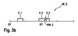
図3は、少なくとも一回の燃料ポスト噴射を備えた本発明に基づく方法の実施の際に現れる複数の噴射モデルを示している。その際、噴射パルス幅ti_1、ti_2、及びti_3は、それぞれ吸気行程Takt_1、圧縮行程Takt_2、作動行程Takt_3、及び排気行程Takt_4からの作動サイクルのクランクシャフト角度 ゜KW の上に高いレベルとして記入されている。上死点はOTで示されている。 FIG. 3 shows a plurality of injection models appearing in the implementation of the method according to the invention with at least one fuel post injection. At that time, the injection pulse widths ti_1, ti_2, and ti_3 are written as high levels on the crankshaft angle ° KW of the operating cycle from the intake stroke Takt_1, the compression stroke Takt_2, the operating stroke Takt_3, and the exhaust stroke Takt_4, respectively. Yes. Top dead center is indicated by OT.
図3aは、吸気行程Takt_1の中で行われる最初の部分噴射ti_1と、その後で行われる第二の部分噴射ti_2とを含む最大化された排気ガスエンタルピーのための均質分割運転のための第一の噴射モデルM_1を示している。第二の部分噴射ti_2は、クランクシャフト角度KW_Zの時に開始される点火の前に行われる。既に述べられたように、クランクシャフト角度KW_Zは状況によっては非常に遅く、上死点OTの後の10゜から30゜までの領域内にあるので、第二の部分噴射もまた、全て或いは一部作動行程Takt_3の中で行われることがある。しかしながら、それは点火の前に行われる。二つの部分噴射に分割する代わりに、第一の噴射モデルM_1によって噴射される燃料量を三つ以上の部分噴射に分割することもできる。分割の可能性は、噴射器24の少量ドーズ能力によって制限される。モデルM_1で重要なのは、少なくとも二回に分割された部分噴射の中の最初の方が、好ましくは吸気行程Takt_1の中にあり、また後の方が同じ作動行程の中の点火の前にあり、その際全体として空気過剰率ラムダLが1よりも大きくなるということである。
FIG. 3a shows the first for a homogeneous split operation for maximized exhaust gas enthalpy including a first partial injection ti_1 performed in the intake stroke Takt_1 and a second partial injection ti_2 performed thereafter. The injection model M_1 is shown. The second partial injection ti_2 is performed before ignition started at the crankshaft angle KW_Z. As already mentioned, the crankshaft angle KW_Z is very slow in some circumstances and is in the region from 10 ° to 30 ° after top dead center OT, so the second partial injection is also all or one. It may be performed in the part operation stroke Takt_3. However, it is done before ignition. Instead of dividing into two partial injections, the amount of fuel injected by the first injection model M_1 can be divided into three or more partial injections. The possibility of splitting is limited by the small dose capability of the
図3bは、点火の後に行われる燃料ポスト噴射ti_3によって第一の噴射モデルM_1とは異なる第二の噴射モデルM_2を示している。従って、少なくとも一回の燃料ポスト噴射ti_3によって噴射される燃料量は少なくとも最早完全には燃焼室12内で燃焼されず、未燃焼燃料量として最大化された排気ガスエンタルピー流の中へ達する。その気化エンタルピーが排気ガスエンタルピーを幾分減少させ、これが、例えばマニホルド31を過熱から保護する。気化された燃料量は排気ガス流と共に触媒28、30の中へ運ばれ、そこで、その他の点では理論値をオーバーしている組成を有する排気ガスからの酸素との発熱反応によって熱の解放をもたらす。好ましい実施態様では、噴射モデルM_2によって噴射される全体の燃料量は、触媒の手前で、噴射モデルM_1の場合の空気過剰率ラムダLよりも1から3%までだけ低い空気過剰率ラムダLが生じるように計量配分される。
FIG. 3b shows a second injection model M_2 that differs from the first injection model M_1 by a fuel post-injection ti_3 performed after ignition. Therefore, the amount of fuel injected by at least one fuel post-injection ti_3 is at least no longer completely burned in the
図4は、本発明に基づく方法の実施例としての流れ図を示している。ステップ58ではスターターの操作の際にスタートプログラムSPが実行され、その際、内燃機関10をスターターの起動によってスタートさせることのできる制御パラメータS_L、S_K、及びS_Zが送り出される。ステップ60では、内燃機関10の回転数nがスタート終了回転数n1をオーバーしているか否かがチェックされる。オーバーしていなければ(n)、プログラムはステップ58へ戻され、スターとプログラム58が更に実施される。
FIG. 4 shows a flow chart as an embodiment of the method according to the invention. In
スタート終了回転数n1がオーバーされるや否や(y)、プログラムはステップ62へ進められ、そこでアイドリング状態にある内燃機関10の制御のためのアフタースタートプログラムNPの流れがスタートされ、その際、時間変数tが値t1にセットされる。この値の下では、スタート終了回転数閾値n1がオーバーされている。その際、アフタースタートプログラムNPによる運転は、先ずHC及びCO等の未燃焼の、削減されるべき排気ガス成分のできるだけ少ない未処理排出物と関連して、大きなエンタルピー流が排気ガス中に生成される。このエンタルピー流は、好ましくは、低減された点火角度効率と、燃焼室12の空気充填効率の引き上げと関連して一回の燃焼室充填毎に噴射される燃料量を吸気行程内での最初の噴射と圧縮行程内での第二の噴射に分割することによって増大される。換言すれば、ステップ62ではアフタースタートプログラムNPの流れが、図3と関連させて説明されていたように、噴射モデルM_1によってスタートされる。
As soon as the start / end speed n1 is exceeded (y), the program proceeds to step 62, where the flow of the after-start program NP for controlling the
その際、噴射されるべき燃料量を二回の噴射に分割することは、点火を上死点OTの後のクランクシャフト角度10゜から30゜までの領域へ移動させることによって、点火角度効率を比較的大きく低下させる可能性をもたらし、このことがトルク損失の補償のための、対応する空気充填効率の引き上げを可能にする。未燃焼の、削減されるべき排気ガス成分の未処理排出をできる限り少なく保持するために、アフタースタートプログラムNPの開始時の空気過剰率ラムダLは1よりも大きなラムダ値、例えばラムダ=1.1、に調節される。この様な運転は、既に上で説明された均質分割運転に相当する。
In this case, dividing the amount of fuel to be injected into two injections is to increase the ignition angle efficiency by moving the ignition to the region between the
アフタースタートプログラムNPの実行の更なる流れの中で、ステップ64では触媒28、30の温度Tに関する尺度、とりわけ触媒28、30の入口での温度Tに関する尺度が測定される。既に説明されたように、この測定は測定及び/又はモデル化によって行われる。
In the further flow of execution of the after-start program NP, in step 64 a measure for the temperature T of the
ステップ66では、増分dtだけの時間変数tの引き上げが行われる。ステップ68では、ステップ64で測定された温度Tに関する尺度が温度閾値T_Sと比較される。温度に関する尺度Tが温度閾値T_Sよりも小さければ、触媒28、30の入口の最初の触媒表面要素も削減されるべき排気ガス成分を未だ全く変換することができないということが推定される。ステップ68での問い合わせは、それに対応して否定“n”と答えられ、プログラムは次いでステップ70へ分岐され、このステップ70で、アフタースタート段階の最大時間長さt_maxが到達されているか否かがチェックされる。この最大時間長さt_maxの一般的な値は、およそ20秒から30秒の間にある。
In
ステップ70での問い合わせが肯定“y”と答えられた場合には、プログラムはステップ72へ進められ、内燃機関10の制御のための主プログラムHPが実行される。この主プログラムHPは、内燃機関10が最早最大化された排気ガス中のエンタルピー流を用いて運転されないという点でアフタースタートプログラムNPとは異なっている。
If the inquiry at
アフタースタート段階の始めに、ステップ70での問い合わせはそれでも“n”と答えられ、プログラムはステップ64及び66へ戻され、これ等のステップで温度Tに関する尺度があらためて求められ且つ時間変数tが更に増分dt一つだけ高められる。この様にすることによって、ステップ64から70までのループが、ステップ68の中止条件或いはステップ70の中止条件が満たされるまで繰り返し実行される。このことはとりわけ、内燃機関10が、通常のコールドスタートの後は、アフタースタートプログラムNPの中で、ステップ68の問い合わせが“y”と答えられるまで、大きなエンタルピー流で、また同時にできるだけ少ない炭化水素排出物で運転されるということを意味している。温度Tに関する尺度としては、スタート終了以後の経過時間を用いることもできる。別の実施態様では、温度に関する尺度として、スタート直前、スタート中、或いはスタート直後の内燃機関10の温度を用いて重み付けをした後のこの時間を用いることができる。この温度が低くなればなる程、より小さな重み付け係数が選ばれるべきである。
At the beginning of the after-start phase, the query at
別の実施態様によれば、本発明に基づく方法は、内燃機関10のスタート過程とは無関係に実施可能である。内燃機関10のコールドスタートの場合の他に、燃料の供給が中止される惰行時カットオフの下での内燃機関10の運転の際にも触媒28、30の冷却が発生するので、触媒28、30の新たな加熱が必要となる。この場合にはスタート過程と関連して説明された方法は無くなり、本発明に基づく方法は主として温度制御されるが、その際には温度に関する尺度について、温度閾値T_Sがオーバーされているか否かと云うチェックが行われる。温度制御の他に例えば惰行(オーバーラン)時カットオフの識別などの他の特性パラメータが考慮されることもある。
According to another embodiment, the method according to the invention can be carried out independently of the starting process of the
ステップ68での問い合わせは、温度Tが温度閾値T_Sをオーバーしている場合には“y”と答えられる。好ましい実施態様では、この閾値T_Sは、予め触媒28、30の最初の表面要素が感じ取れる程の規模で、排気ガス中の酸素供給を用いた発熱反応を触媒によって開始させることによって、削減すべき排気ガス成分の変換を開始する温度に等しくなるように定められている。この発熱反応によって解放された反応熱が触媒28、30の加速された加熱のために高度に活用されるようにするために、ステップ74で内燃機関10の運転の活性化が行われ、その中で燃焼の開始の後に少なくとももう一回の燃料ポスト噴射が行われる。従って、アフタースタートプログラムNPは、図3bに関連して説明されたように、噴射モデルM_2を用いて実行される。
The inquiry at
少なくとも一回の燃料ポスト噴射に対する追加として或いは代わりとして、その他の措置が、削減されるべき排気ガス成分の量を引き上げるために内燃機関10の制御への介入によって行われることがある。
In addition to or as an alternative to at least one fuel post injection, other measures may be taken by intervention in the control of the
追加として或いは代わりの手法として、例えば、点火角遅延を減らすこと、従って点火角効率を僅かに引き上げることが行われる。
追加として或いは代わりの手法として、例えば、個々の燃料部分噴射の中でドーズされる燃料量の配分を変化させることが行われる。
In addition or as an alternative, for example, reducing the ignition angle delay and thus slightly increasing the ignition angle efficiency.
In addition or as an alternative, for example, the distribution of the amount of fuel dosed in individual fuel partial injections is changed.
更に追加として或いは代わりの手法として、例えば、空気過剰率ラムダLを幾分希薄となるように調節することが行われる。
これ等の諸措置の中の何れが単独で或いは他の措置と組み合わせることによって最大の効果を発揮するかということは、内燃機関10の構成に依存している。従って、個々の措置或いは諸措置の組み合わせはテストによって特定され、それに応じてプログラミングされるべきである。ステップ68で“y”と答えられた後のこの方法の実施の間に、空気過剰率ラムダLを1から3%まで、例えばラムダL=1.1からラムダL=1.08まで連続的に引き下げて行くことは、とりわけ適切な措置であると考えられている。
As an additional or alternative approach, for example, the excess air lambda L is adjusted to be somewhat leaner.
It depends on the configuration of the
点火角遅延の縮小もまた、HC未処理排出物の増加をもたらす。内燃機関10でのテストでは、例えば、点火角遅延の縮小はHC未処理排出物のおよそ3%の増加をもたらすことがあるということが示されている。その際には、場合によっては排気ガス温度の低下をも甘受しなければならない。
Reduction in ignition angle delay also results in an increase in HC untreated emissions. Tests with the
空気過剰率ラムダは、二回の燃料部分噴射によって噴射される全体の燃料量を増やすことによって高めることができる。代わりの手法として、個々の燃料部分噴射の中でドーズされる燃料量の配分を変えることもできる。 The excess air lambda can be increased by increasing the total amount of fuel injected by two fuel partial injections. As an alternative, the distribution of the amount of fuel that is dosed in individual fuel partial injections can be changed.
ステップ74に続くステップ76では、時間変数tが増分dtだけ高められる。ステップ78では、ステップ70での問い合わせと同様にして、時間変数tが増分dtずつの何回かの引き上げの後で、閾値t_maxをオーバーしているか否かがチェックされる。閾値をオーバーしていなければ、ステップ78での問い合わせは“n”で答えられ、プログラムはステップ74へ戻され、そこで運転は第二の噴射モデルM_2を用いて続行される。一実施態様の場合には、もう一つの部分噴射ti_3によって噴射される燃料量がその際に連続的に引き上げられ、且つそれによって、加熱の進行に伴って触媒28、30の奥へと進んで行く変換能力に適応される。一実施態様では、少なくとも一回の燃料ポスト噴射ti_3によって行われる未燃焼排気ガス成分の排出の増加は、ステップ78での時間閾値t_maxがオーバーされた時に終了する。この場合、アフタースタート段階或いは一般に本発明に基づく方法は終了し、プログラムはステップ72へ進められ、このステップ72で、既に説明された内燃機関10の制御のための主プログラムHPが排気ガス中のエンタルピー流を増加させること無しに実行される。
In
図2aにおける破線のグラフ80は本発明の効果を定性的に示している。この破線のグラフ80は、グラフ50と同様、アフタースタート段階或いは通常の触媒加熱運転における触媒28、30の中央領域の温度Tの時間的変化を示している。図示のように、グラフ50と80の動きは時点t2までは平行或いは同一である。その理由は、時点t2までは既知の方法と何ら違いが無いことにある。即ちとりわけ、本発明の場合にもアフタースタート段階の開始時には或いは触媒加熱措置の開始時には、内燃機関10は増加されたエンタルピー流で、また同時に未燃焼排気ガス成分のできる限り少ない未処理排出で運転される。既知の方法の場合に得られるグラフ50と本発明に基づく方法に従って得られるグラフ80との間の違いは、温度Tが温度閾値T_Sに到達した時点t2から始まる。一実施例では、この温度閾値T_Sは、例えば380℃と420℃の間にある。この値は相当程度触媒28、30に依存している。時間t>t2では、本発明の枠組みの中で高められた、未処理炭化水素の未処理排出が少なくとも触媒28、30の入口で始まる変換能力と相俟って、増加されたエンタルピー流だけによって可能であるよりもより効果的に触媒28、30を加熱する、排気ガス中の酸素供給による発熱反応をもたらす。その結果として、本発明に基づく方法の場合に得られる破線で示されたグラフ80は、既知の方法の場合に得られるグラフ50よりもより速く上昇して行く。
The
図示のように、触媒28、30の手前での温度のグラフ48と既知の方法を用いて達成される、触媒28、30の中央領域の温度のグラフ50との間には、比較的大きな差がある。既に説明されたように、この差、或いは、触媒28、30の温度T、とりわけ触媒28、30の入口での温度が定められた温度閾値T_Sに到達する時点と、触媒28、30の中央の領域の温度がこの温度に到達する時点との間の時間的間隔が、触媒28、30が冷たい時に環境中へ放出される炭化水素排出物の大部分の原因となっている。本発明に基づく方法によって得られる破線で示されたグラフ80と、とりわけ触媒28、30の入口での温度Tの変化を反映している曲線48との比較は、この差が本発明に基づく方法の場合には既知の方法の場合よりも大幅に小さくなっているということを示している。このことは、直接、触媒28、30が未だ冷たい時の環境中への炭化水素排出に対する削減効果をもたらす。
As shown, there is a relatively large difference between the
Claims (17)
内燃機関(10)が、次善の点火角度効率と、燃焼の開始前に噴射される燃料量の少なくとも二つの部分噴射(ti_1、ti_2)への分割とによって作動され、
次善の点火角度効率及び噴射される燃料量の分割の少なくともいずれから生じるトルク損失が、燃焼室(12)の引き上げられた充填効率によって補償され、
燃料量と充填効率が、互いに燃焼室充填気の空気過剰率ラムダ(L)が1よりも大きくなるように調整されている、内燃機関(10)の排気ガス領域(26)内に配置された触媒(28、30)の加熱方法において、
触媒(28、30)の温度(T)に関する尺度が測定され、この温度(T)に関する尺度が予め定められた温度閾値(T_S)をオーバーすると、減少させるべき排気ガス成分の量が、内燃機関(10)の制御装置内への少なくとも一回の介入によって引き上げられること、
を特徴とする内燃機関の排気ガス領域内に配置された触媒の加熱方法。 The internal combustion engine is operated by direct fuel injection into the combustion chamber (12);
The internal combustion engine (10) is operated by suboptimal ignition angle efficiency and division of the amount of fuel injected before the start of combustion into at least two partial injections (ti_1, ti_2);
Torque loss resulting from at least one of sub-optimal ignition angle efficiency and split of injected fuel quantity is compensated by the increased charging efficiency of the combustion chamber (12),
The fuel amount and the charging efficiency are arranged in the exhaust gas region (26) of the internal combustion engine (10), which is adjusted so that the excess air lambda (L) of the combustion chamber charge is greater than 1. In the method for heating the catalyst (28, 30),
When a measure for the temperature (T) of the catalyst (28, 30) is measured and this measure for temperature (T) exceeds a predetermined temperature threshold (T_S), the amount of the exhaust gas component to be reduced is determined by the internal combustion engine. (10) being lifted by at least one intervention in the control device;
A method for heating a catalyst disposed in an exhaust gas region of an internal combustion engine.
減少させるべき排気ガス成分の量の引き上げが、空気過剰率ラムダ(L)が1から3%までだけ引き下げられるように定められること、
を特徴とする請求項1に記載の加熱方法。 The excess air lambda in the exhaust gas before the catalyst (18) is adjusted to a value greater than 1 during the heating process and the increase in the amount of exhaust gas component to be reduced The rate lambda (L) is set to be reduced from 1 to 3%,
The heating method according to claim 1.
Applications Claiming Priority (3)
| Application Number | Priority Date | Filing Date | Title |
|---|---|---|---|
| DE102006061687A DE102006061687A1 (en) | 2006-12-28 | 2006-12-28 | Catalyzer i.e. precatalytic converter, heating method for control device, involves determining measure for temperature at input of converter, and carrying out additional injection, if temperature exceeds preset threshold value |
| DE102006061694A DE102006061694A1 (en) | 2006-12-28 | 2006-12-28 | Catalyst heating method for exhaust gas of internal combustion engine, involves continuously increasing amount of reducing exhaust gas components by interferences in controller of engine, if temperature exceeds threshold value |
| PCT/EP2007/064586 WO2008080952A1 (en) | 2006-12-28 | 2007-12-27 | Method for heating a catalytic converter arranged in an exhaust-gas region of a combustion process, and device for carrying out the method |
Related Child Applications (1)
| Application Number | Title | Priority Date | Filing Date |
|---|---|---|---|
| JP2013168874A Division JP2013231447A (en) | 2006-12-28 | 2013-08-15 | Method and device for heating catalyst disposed in exhaust gas region of internal combustion engine |
Publications (2)
| Publication Number | Publication Date |
|---|---|
| JP2011502222A true JP2011502222A (en) | 2011-01-20 |
| JP2011502222A5 JP2011502222A5 (en) | 2011-03-03 |
Family
ID=39262713
Family Applications (3)
| Application Number | Title | Priority Date | Filing Date |
|---|---|---|---|
| JP2009543472A Pending JP2011502222A (en) | 2006-12-28 | 2007-12-27 | Method and apparatus for heating a catalyst disposed in an exhaust gas region of an internal combustion engine |
| JP2013168874A Pending JP2013231447A (en) | 2006-12-28 | 2013-08-15 | Method and device for heating catalyst disposed in exhaust gas region of internal combustion engine |
| JP2015248600A Pending JP2016040468A (en) | 2006-12-28 | 2015-12-21 | Heating method and device for catalyst disposed in exhaust gas region of internal combustion engine |
Family Applications After (2)
| Application Number | Title | Priority Date | Filing Date |
|---|---|---|---|
| JP2013168874A Pending JP2013231447A (en) | 2006-12-28 | 2013-08-15 | Method and device for heating catalyst disposed in exhaust gas region of internal combustion engine |
| JP2015248600A Pending JP2016040468A (en) | 2006-12-28 | 2015-12-21 | Heating method and device for catalyst disposed in exhaust gas region of internal combustion engine |
Country Status (6)
| Country | Link |
|---|---|
| US (1) | US8312709B2 (en) |
| EP (1) | EP2126318B1 (en) |
| JP (3) | JP2011502222A (en) |
| AT (1) | ATE486205T1 (en) |
| DE (1) | DE502007005506D1 (en) |
| WO (1) | WO2008080952A1 (en) |
Families Citing this family (12)
| Publication number | Priority date | Publication date | Assignee | Title |
|---|---|---|---|---|
| EP1863105B1 (en) | 2006-06-02 | 2020-02-19 | Semiconductor Energy Laboratory Co., Ltd. | Light-emitting element, light-emitting device, and electronic device |
| DE102008032741B3 (en) * | 2008-07-11 | 2010-02-18 | Continental Automotive Gmbh | Method and diagnostic device for detecting a malfunction in an injection system |
| US8261542B2 (en) * | 2008-09-03 | 2012-09-11 | General Electric Company | System, method, and device for locomotive exhaust gas recirculation cooling and catalyst heating |
| US8776562B2 (en) * | 2011-09-30 | 2014-07-15 | GMS Industries, Inc. | System and method for automating lock cylinder pinning for remote users |
| DE202014009562U1 (en) * | 2014-12-04 | 2016-03-07 | GM Global Technology Operations LLC (n. d. Ges. d. Staates Delaware) | Determining the amount of post-injection fuel in an internal combustion engine |
| GB2550422B (en) * | 2016-05-20 | 2019-12-04 | Caterpillar Inc | Method of controlling operation of an exhaust gas treatment apparatus |
| JP6784214B2 (en) * | 2017-04-12 | 2020-11-11 | トヨタ自動車株式会社 | Internal combustion engine control device |
| US10808594B2 (en) * | 2018-04-20 | 2020-10-20 | GM Global Technology Operations LLC | Generalized cold start emissions reduction strategy |
| GB2584427B (en) * | 2019-05-29 | 2021-11-10 | Jaguar Land Rover Ltd | Controller for a vehicle internal combustion engine |
| GB2585053B (en) * | 2019-06-26 | 2022-01-05 | Jaguar Land Rover Ltd | A controller and a method for controlling an internal combustion engine |
| CN111608774B (en) * | 2020-04-09 | 2021-12-17 | 东风汽车集团有限公司 | Method for accelerating ignition process of catalytic converter by utilizing ignition efficiency of engine |
| DE102022120837A1 (en) | 2022-08-18 | 2024-02-29 | Volkswagen Aktiengesellschaft | Method for reducing cold start emissions of an internal combustion engine |
Citations (6)
| Publication number | Priority date | Publication date | Assignee | Title |
|---|---|---|---|---|
| JPH06101456A (en) * | 1992-09-21 | 1994-04-12 | Nissan Motor Co Ltd | Air amount control device for internal combustion engine |
| JPH10212987A (en) * | 1997-01-30 | 1998-08-11 | Mazda Motor Corp | In-cylinder injection type engine |
| JP2000045844A (en) * | 1998-08-03 | 2000-02-15 | Mazda Motor Corp | Control device for cylinder injection type engine |
| JP2000054837A (en) * | 1998-08-06 | 2000-02-22 | Mitsubishi Motors Corp | Catalyst temperature raising device for internal combustion engine |
| JP2000120471A (en) * | 1998-08-10 | 2000-04-25 | Mazda Motor Corp | Cylinder injection type engine control device |
| JP2002221062A (en) * | 2001-01-26 | 2002-08-09 | Fuji Heavy Ind Ltd | Control device of engine |
Family Cites Families (15)
| Publication number | Priority date | Publication date | Assignee | Title |
|---|---|---|---|---|
| JP2671606B2 (en) * | 1990-12-27 | 1997-10-29 | トヨタ自動車株式会社 | Fuel injection controller for direct injection type internal combustion engine |
| US5845492A (en) * | 1995-09-18 | 1998-12-08 | Nippondenso Co., Ltd. | Internal combustion engine control with fast exhaust catalyst warm-up |
| US7127883B1 (en) * | 1997-11-10 | 2006-10-31 | Mitsubishi Jidosha Kogoyo Kabushiki Kaisha | Exhaust gas purifying apparatus of internal combustion engine |
| US7886523B1 (en) * | 1998-08-24 | 2011-02-15 | Legare Joseph E | Control methods for improved catalytic converter efficiency and diagnosis |
| JP4362916B2 (en) * | 2000-01-20 | 2009-11-11 | マツダ株式会社 | Engine exhaust purification system |
| JP4250856B2 (en) * | 2000-05-24 | 2009-04-08 | 三菱自動車工業株式会社 | In-cylinder internal combustion engine |
| DE10043366A1 (en) * | 2000-09-02 | 2002-03-14 | Bosch Gmbh Robert | Process for heating catalysts in the exhaust gas of internal combustion engines |
| DE10043375A1 (en) * | 2000-09-02 | 2002-03-14 | Bosch Gmbh Robert | Process for heating a catalytic converter in internal combustion engines with gasoline direct injection |
| DE10100682A1 (en) * | 2001-01-09 | 2002-07-11 | Bosch Gmbh Robert | Process for heating a catalytic converter in internal combustion engines with gasoline direct injection |
| JP2003138960A (en) * | 2001-11-05 | 2003-05-14 | Denso Corp | Catalyst pre-warmup control device of internal combustion engine |
| US6868827B2 (en) * | 2002-06-04 | 2005-03-22 | Ford Global Technologies, Llc | Method for controlling transitions between operating modes of an engine for rapid heating of an emission control device |
| US7168239B2 (en) * | 2002-06-04 | 2007-01-30 | Ford Global Technologies, Llc | Method and system for rapid heating of an emission control device |
| DE102004017988B4 (en) | 2004-04-14 | 2014-01-02 | Daimler Ag | Method for operating an internal combustion engine with direct fuel injection |
| JP4539439B2 (en) * | 2005-05-31 | 2010-09-08 | 日産自動車株式会社 | In-cylinder direct injection spark ignition internal combustion engine controller |
| US7748362B2 (en) * | 2008-05-08 | 2010-07-06 | Gm Global Technology Operations, Inc. | Managing lean air/fuel transients in coordinated torque control |
-
2007
- 2007-12-27 AT AT07858182T patent/ATE486205T1/en active
- 2007-12-27 US US12/514,997 patent/US8312709B2/en active Active
- 2007-12-27 JP JP2009543472A patent/JP2011502222A/en active Pending
- 2007-12-27 WO PCT/EP2007/064586 patent/WO2008080952A1/en active Application Filing
- 2007-12-27 EP EP07858182A patent/EP2126318B1/en active Active
- 2007-12-27 DE DE502007005506T patent/DE502007005506D1/en active Active
-
2013
- 2013-08-15 JP JP2013168874A patent/JP2013231447A/en active Pending
-
2015
- 2015-12-21 JP JP2015248600A patent/JP2016040468A/en active Pending
Patent Citations (6)
| Publication number | Priority date | Publication date | Assignee | Title |
|---|---|---|---|---|
| JPH06101456A (en) * | 1992-09-21 | 1994-04-12 | Nissan Motor Co Ltd | Air amount control device for internal combustion engine |
| JPH10212987A (en) * | 1997-01-30 | 1998-08-11 | Mazda Motor Corp | In-cylinder injection type engine |
| JP2000045844A (en) * | 1998-08-03 | 2000-02-15 | Mazda Motor Corp | Control device for cylinder injection type engine |
| JP2000054837A (en) * | 1998-08-06 | 2000-02-22 | Mitsubishi Motors Corp | Catalyst temperature raising device for internal combustion engine |
| JP2000120471A (en) * | 1998-08-10 | 2000-04-25 | Mazda Motor Corp | Cylinder injection type engine control device |
| JP2002221062A (en) * | 2001-01-26 | 2002-08-09 | Fuji Heavy Ind Ltd | Control device of engine |
Also Published As
| Publication number | Publication date |
|---|---|
| US8312709B2 (en) | 2012-11-20 |
| ATE486205T1 (en) | 2010-11-15 |
| JP2013231447A (en) | 2013-11-14 |
| JP2016040468A (en) | 2016-03-24 |
| EP2126318B1 (en) | 2010-10-27 |
| EP2126318A1 (en) | 2009-12-02 |
| DE502007005506D1 (en) | 2010-12-09 |
| US20100024392A1 (en) | 2010-02-04 |
| WO2008080952A1 (en) | 2008-07-10 |
Similar Documents
| Publication | Publication Date | Title |
|---|---|---|
| JP2016040468A (en) | Heating method and device for catalyst disposed in exhaust gas region of internal combustion engine | |
| US10975789B2 (en) | Systems and methods for expediting engine warming | |
| JP4689723B2 (en) | Method for cold operation of a spark ignition internal combustion engine | |
| JP5482715B2 (en) | Diesel engine and control method of diesel engine | |
| RU2669121C2 (en) | Method for fuel injection control (options) | |
| JP4427744B2 (en) | Direct fuel injection internal combustion engine operation method | |
| US6739295B1 (en) | Compression ignition internal combustion engine | |
| JP4781419B2 (en) | Method and controller for heating catalyst | |
| JP4023115B2 (en) | Control device for direct-injection spark ignition engine | |
| JP5136721B2 (en) | Fuel injection control device for internal combustion engine | |
| US9745914B2 (en) | Control apparatus for internal combustion engine | |
| US9932916B2 (en) | Combustion control apparatus for internal combustion engine | |
| US9784207B2 (en) | Control apparatus for internal combustion engine | |
| JP4861470B2 (en) | Driving method for internal combustion engine | |
| US20110220084A1 (en) | Method for operating an internal combustion engine | |
| US10066574B2 (en) | Control apparatus for internal combustion engine | |
| US9587617B2 (en) | Method of spark timing adjustment for an internal combustion engine | |
| US11306672B2 (en) | Use of different pneumatic cylinder spring types in a variable displacement engine for engine and aftertreatment system temperature control | |
| US20030226528A1 (en) | Compression ignition internal combustion engine | |
| JP4032859B2 (en) | Control device for direct-injection spark ignition engine | |
| JP2004507654A (en) | Method for heating catalyst in exhaust gas of internal combustion engine | |
| JP2017145735A (en) | Control device for internal combustion engine and warming-up method for exhaust emission control catalyst | |
| JP2002295287A (en) | Spark ignition type direct injection engine equipped with turbo supercharger | |
| JP2004028031A (en) | Control device and method of direct injection spark ignition-type engine | |
| JP2007321696A (en) | Control device for cylinder direct injection type spark ignition internal combustion engine |
Legal Events
| Date | Code | Title | Description |
|---|---|---|---|
| A621 | Written request for application examination |
Free format text: JAPANESE INTERMEDIATE CODE: A621 Effective date: 20101227 |
|
| A131 | Notification of reasons for refusal |
Free format text: JAPANESE INTERMEDIATE CODE: A131 Effective date: 20120521 |
|
| A977 | Report on retrieval |
Free format text: JAPANESE INTERMEDIATE CODE: A971007 Effective date: 20120524 |
|
| A601 | Written request for extension of time |
Free format text: JAPANESE INTERMEDIATE CODE: A601 Effective date: 20120820 |
|
| A602 | Written permission of extension of time |
Free format text: JAPANESE INTERMEDIATE CODE: A602 Effective date: 20120827 |
|
| A521 | Request for written amendment filed |
Free format text: JAPANESE INTERMEDIATE CODE: A523 Effective date: 20121119 |
|
| A02 | Decision of refusal |
Free format text: JAPANESE INTERMEDIATE CODE: A02 Effective date: 20130430 |