JP2011254073A - Roll screen system - Google Patents
Roll screen system Download PDFInfo
- Publication number
- JP2011254073A JP2011254073A JP2011102258A JP2011102258A JP2011254073A JP 2011254073 A JP2011254073 A JP 2011254073A JP 2011102258 A JP2011102258 A JP 2011102258A JP 2011102258 A JP2011102258 A JP 2011102258A JP 2011254073 A JP2011254073 A JP 2011254073A
- Authority
- JP
- Japan
- Prior art keywords
- solar cell
- roll screen
- cell module
- roll
- film
- Prior art date
- Legal status (The legal status is an assumption and is not a legal conclusion. Google has not performed a legal analysis and makes no representation as to the accuracy of the status listed.)
- Pending
Links
Images


Classifications
-
- Y—GENERAL TAGGING OF NEW TECHNOLOGICAL DEVELOPMENTS; GENERAL TAGGING OF CROSS-SECTIONAL TECHNOLOGIES SPANNING OVER SEVERAL SECTIONS OF THE IPC; TECHNICAL SUBJECTS COVERED BY FORMER USPC CROSS-REFERENCE ART COLLECTIONS [XRACs] AND DIGESTS
- Y02—TECHNOLOGIES OR APPLICATIONS FOR MITIGATION OR ADAPTATION AGAINST CLIMATE CHANGE
- Y02E—REDUCTION OF GREENHOUSE GAS [GHG] EMISSIONS, RELATED TO ENERGY GENERATION, TRANSMISSION OR DISTRIBUTION
- Y02E10/00—Energy generation through renewable energy sources
- Y02E10/50—Photovoltaic [PV] energy
- Y02E10/549—Organic PV cells
Abstract
Description
本発明は、複数のロールスクリーンを含むロールスクリーンシステムに関する。 The present invention relates to a roll screen system including a plurality of roll screens.
太陽電池は、太陽光がありさえすれば発電が可能な、CO2などの温室効果ガスを発生
しないクリーンなエネルギー源である。そして、ロールスクリーンは、窓等から屋内に日光が入り込まないようにするために窓際に配置される装置であるため、ロールスクリーンにて遮蔽する日光を有効利用するために、ロールスクリーンのスクリーン部分に太陽電池を取り付けること(例えば、特許文献1、2参照。)が提案されている。
A solar cell is a clean energy source that does not generate greenhouse gases such as CO 2 that can generate electricity as long as there is sunlight. And since the roll screen is a device arranged near the window to prevent sunlight from entering the indoors through windows, etc., in order to effectively use the sunlight shielded by the roll screen, It has been proposed to attach a solar cell (for example, see Patent Documents 1 and 2).
さて、ロールスクリーンは、通常、複数個並べて使用されるものである。従って、太陽電池を設けたロールスクリーンも複数個並べて使用されることになるが、太陽電池が設けられている複数のロールスクリーンを使用する場合における各太陽電池の出力の有効な利用法は未だ開発されていないのが現状である。 Now, a plurality of roll screens are usually used side by side. Therefore, a plurality of roll screens provided with solar cells will be used side by side, but effective use of the output of each solar cell is still developed when using a plurality of roll screens provided with solar cells. The current situation is not.
特に、ロールスクリーンの巻上げ履歴によっては、各ロールスクリーン上の太陽電池の劣化状況が異なり、一部の太陽電池が劣化することによるシステム全体のダメージを受ける可能性がある。また、ローススクリーンを室内に設置する場合には、窓枠による陰により太陽電池の一部に太陽光が当たらない箇所ができるため、複数の太陽電池において各太陽電池の出力がことなる。従って、複数の太陽電池をシステムとして管理する必要がある。 In particular, depending on the roll screen winding history, the deterioration state of the solar cells on each roll screen is different, and there is a possibility that the entire system is damaged due to deterioration of some of the solar cells. In addition, when the loin screen is installed indoors, there is a place where sunlight does not hit a part of the solar cell due to the shadow of the window frame, and thus the output of each solar cell is different in a plurality of solar cells. Therefore, it is necessary to manage a plurality of solar cells as a system.
そこで、本発明の課題は、太陽電池を備えた複数のロールスクリーンを含むロールスクリーンシステムであって、上記のような場合においても各太陽電池の出力を有効に利用できるロールスクリーンシステムを提供することにある。 Therefore, an object of the present invention is to provide a roll screen system including a plurality of roll screens equipped with solar cells, and can effectively use the output of each solar cell even in the above case. It is in.
上記課題を解決するために、本発明のロールスクリーンシステムは、それぞれ、太陽電池が配設されたスクリーンを有する複数のロールスクリーンと、各ロールスクリーンの太陽電池の正極と電気的に接続された第1電極と、各ロールスクリーンの太陽電池の負極と電気的に接続された第2電極とを、備える。 In order to solve the above-described problems, a roll screen system according to the present invention includes a plurality of roll screens each having a screen on which solar cells are disposed, and a first electrically connected to the positive electrode of the solar cell of each roll screen. 1 electrode and the 2nd electrode electrically connected with the negative electrode of the solar cell of each roll screen are provided.
すなわち、複数のロールスクリーンの太陽電池を直列接続した場合、或るロールスクリーンのスクリーンが、破損若しくは劣化した場合や、巻き上げられただけで、システム全体の出力が著しく低下することになる。一方、上記構成が採用されている本発明のロールスクリーンシステムでは、何台かのロールスクリーンのスクリーンが巻き上げられても、システム全体の出力低下を抑えることができる。従って、本発明のロールスクリーンシステムは、各ロールスクリーンの太陽電池の出力を有効に利用できるシステムとなっていると言うことが出来る。 That is, when solar cells of a plurality of roll screens are connected in series, the output of the entire system is significantly reduced when a roll screen is damaged or deteriorated, or just rolled up. On the other hand, in the roll screen system of the present invention in which the above configuration is adopted, even if the screens of several roll screens are rolled up, the output reduction of the entire system can be suppressed. Therefore, it can be said that the roll screen system of the present invention is a system that can effectively use the output of the solar cell of each roll screen.
本発明のロールスクリーンシステムを実現する際には、複数のロールスクリーンの設置場所に配置される固定用部材であって、複数のロールスクリーンの中の特定のロールスクリーンのスクリーンの下端側を、当該スクリーンが重力方向に対して10°以上傾くように固定するための固定用部材を、システムの構成要素としておくことが好ましい。何故ならば、スクリーン(太陽電池)に対する光の入射角度が小さいと、反射率が大きくなるため、光電変換効率が低下するが、スクリーンを傾ければ、光の入射角度がより大きくなる結果として、光電変換効率を向上させることが出来るからである。また、個々のモジュール効率が向上することで、影部によるPV破損の度合いが悪化する恐れがあるが、複数の太陽電池のシステムとして出力を高くするとともに前記破損を低減できる。 When realizing the roll screen system of the present invention, it is a fixing member disposed at a place where a plurality of roll screens are installed, and the lower end side of the screen of a specific roll screen in the plurality of roll screens is It is preferable that a fixing member for fixing the screen so as to be inclined by 10 ° or more with respect to the direction of gravity is a component of the system. This is because if the incident angle of light with respect to the screen (solar cell) is small, the reflectivity increases and the photoelectric conversion efficiency decreases. However, if the screen is tilted, the incident angle of light becomes larger. This is because the photoelectric conversion efficiency can be improved. Moreover, although the degree of PV breakage due to shadows may deteriorate due to improvement in individual module efficiency, the damage can be reduced while increasing the output as a system of a plurality of solar cells.
本発明のロールスクリーンシステムは、各ロールスクリーンが、スクリーンを巻き取るための巻取パイプ内を経由して、太陽電池の正極及び負極とそれぞれ電気的に接続された第1端子及び第2端子を備え、第1電極が、各ロールスクリーンと第1端子と電気的に接続されており、第2電極が、各ロールスクリーンと第2端子と電気的に接続されているシステムとして実現しておくことも、各スクリーンの太陽電池の正極及び負極が各スクリーンの下端側に設けられているシステムとして実現しておくことも出来る。 In the roll screen system of the present invention, each roll screen has a first terminal and a second terminal electrically connected to a positive electrode and a negative electrode of a solar cell, respectively, through a winding pipe for winding the screen. The first electrode is electrically connected to each roll screen and the first terminal, and the second electrode is realized as a system electrically connected to each roll screen and the second terminal. Alternatively, it can be realized as a system in which the positive electrode and the negative electrode of the solar cell of each screen are provided on the lower end side of each screen.
また、本発明のロールスクリーンシステムを、複数のロールスクリーンのそれぞれのスクリーン上に配設されている太陽電池が、複数の太陽電池ユニットをスクリーンの巻き取り方向に並べ、各太陽電池ユニットを並列接続した太陽電池であるシステムとして実現しておくことも出来る。 Moreover, the solar cell arranged on each screen of the plurality of roll screens in the roll screen system of the present invention is arranged in the winding direction of the screen, and the solar cell units are connected in parallel. It can also be realized as a system that is a solar cell.
本発明によれば、各太陽電池の出力を有効に利用できるロールスクリーンシステムを提供することが出来る。 ADVANTAGE OF THE INVENTION According to this invention, the roll screen system which can utilize the output of each solar cell effectively can be provided.
以下、本発明の実施の形態について、図面を参照して詳細に説明する。 Hereinafter, embodiments of the present invention will be described in detail with reference to the drawings.
図1に模式的に示したように、本発明の一実施形態に係るロールスクリーンシステムは、複数のロールスクリーン100、充放電コントローラ110、蓄電池120及び2つの出力端子130を備えたシステムである。
As schematically shown in FIG. 1, the roll screen system according to an embodiment of the present invention is a system including a plurality of
このロールスクリーンシステムが備える2つの出力端子130は、直流電圧(電流)にて動作する機器(照明器具等)が接続される端子である。各出力端子130には、蓄電池120(及び充放電コントローラ110)の各出力端子が接続されている。
The two
充放電コントローラ110は、ロールスクリーン100群からの電力(後述する太陽電池モジュール10群からの電力)で蓄電池120を充電する回路である。
The charge /
ロールスクリーン100は、スクリーンとしての太陽電池モジュール10、巻取パイプ30等から構成された装置である。
The
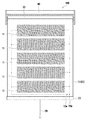
より具体的には、このロールスクリーン100は、図2に示したように、太陽電池モジュール10、巻取パイプ30、保持部40等から構成された,一種のプルコード式(スプリング式)ロールスクリーンとなっている。
More specifically, as shown in FIG. 2, the
太陽電池モジュール10は、可撓性を有する矩形状基材20の一方の面側に、複数の長方形状の太陽電池ユニット11を、各太陽電池ユニット11の長手方向が太陽電池モジュール10の巻取パイプ30による巻取り方向と直交するように並設したモジュールである。また、太陽電池モジュール10は、各太陽電池ユニット11の正極端子と接続された出力端子10p、及び、各太陽電池ユニット11の負極端子と接続された出力端子10mを備えたモジュール(つまり、各太陽電池ユニット11を並列接続したモジュール)ともなっている。なお、本明細書において、太陽電池ユニット11とは、1組の出力端子(正極端子及び負極端子)を有する1つの太陽電池素子、或いは、複数の太陽電池素子が直列接続(又は直並列接続)された,1組の出力端子を有する素子(ユニット)のことである。
The
この太陽電池モジュール10としては、上記構成を有するものでありさえすれば、具体的な構成の異なる様々なものを使用することが出来る。
As this
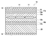
例えば、太陽電池モジュール10として、図3Aに示したように、耐候性保護フィルム12、封止材13a、複数の太陽電池ユニット11、封止材13b、バックシート14、シール材15、矩形状基材20からなるものや、図3Bに示したように、図3Aに示したものからシール材15を取り除いたものを使用することが出来る。また、図4Aに示したように、耐候性保護フィルム12、封止材13a、複数の太陽電池ユニット11、封止材13b、バックシート14、シール材15、矩形状基材20からなるものや、図4Bに示したように、図4Aに示したものからシール材15を取り除いたものも使用することが出来る。さらに、図4Cに示したように、矩形状基材20の裏面側にバックシート14を設けたものを使用することが出来る。なお、各太陽電池モジュール10の各構成要素の詳細については、太陽電池モジュール10の製造手順と共に、後ほどまとめて説明する。
For example, as shown in FIG. 3A, as the
保持部40(図2)は、複数の部材を組み合わせることによって構成された、巻取パイプ30を回転可能な形で保持するためのユニットである。ロールスクリーン100の窓への取り付け時には、この保持部40が、窓枠内/窓枠外に、直接或いは他部材を介して固
定される。
The holding unit 40 (FIG. 2) is a unit configured to hold the winding
巻取パイプ30は、太陽電池モジュール10を巻き取るためのパイプ状部材である。この巻取パイプ30の外径は、(1)太陽電池モジュール10の長さ、(2)巻取パイプ30の外径が小さ過ぎると、太陽電池モジュール10の巻き取り時に太陽電池モジュール10が損傷しやすくなること、(3)巻取パイプ30の外径が大きすぎると、巻取パイプ30の重量および体積が増すため施工性が悪くなること、等を考慮して定めるべきものである。なお、巻取パイプ30の構成材料は何であっても構わないが、アルミニウムが軽量であるため、好適である。
The winding
巻取パイプ30による巻き取りを可能とするために、太陽電池モジュール10の一端(以下、上端と表記する)は、巻取パイプ30の外周面に固定されている。また、太陽電池モジュール10の上端と平行な他端(以下、下端と表記する)には、錘等として機能するボトムバー27が取り付けられている。ボトムバー27の中央部分には、太陽電池モジュール10の昇降操作を行うためのプルコード29が取り付けられている。
In order to enable winding by the winding
本ロールスクリーンシステムの構成要素として使用するロールスクリーン100は、太陽電池モジュール10を図5(a)に示してある形で巻取パイプ30に巻き取るものであっても、太陽電池モジュール10を図5(b)に示してある形で巻取パイプ30に巻き取るものであっても良い。ただし、太陽電池モジュール10に相当する構成の実験用モジュールを、その太陽電池ユニット側の面(以下、PV面と表記する)を外側/内側に向けた状態でさまざまな外径のパイプに繰り返し巻き付け、その後、その性能(短絡電流、開放電圧)を測定する実験により、図6(a)、(b)に示した結果が得られている。すなわち、巻取パイプ30の外径(図6における巻き径)が小さい場合には、PV面が外側を向く形で太陽電池モジュール10を巻取パイプ30に巻き取った方(図6(b))が、太陽電池ユニット11の性能(短絡電流、開放電圧)が劣化し難いことが分かっている。なお、図6(a)、(b)において、“短絡電流(規格化)”とは、“実験用モジュールの,或る巻き径のパイプへの巻き付けを1000回繰り返した後の短絡電流”/“実験用モジュールの初期状態における短絡電流”のことである。また、“開放電圧(規格化)”とは、同様に、“実験用モジュールの,或る巻き径のパイプへの巻き付けを1000回繰り返した後の開放電圧”/“実験用モジュールの初期状態における開放電圧”のことである。
The
そのため、ロールスクリーン100は、PV面が外側を向く形で太陽電池モジュール10を巻取パイプ30に巻き取るものとしておくことが望ましい。
Therefore, it is desirable that the
巻取パイプ30(図2)内には、巻取パイプ30に、太陽電池モジュール10の巻き取り方向の回転力を付勢するための付勢機構(図示略)が設けられている。巻取パイプ30内には、太陽電池モジュール10の巻き上げ速度が、常に、所定速度以下となるように(過度に高速にならないように)するためのブレーキ機構(図示略)も設けられている。
In the winding pipe 30 (FIG. 2), an urging mechanism (not shown) for urging the winding
さらに、巻取パイプ30内には、付勢機構により回転力が付勢されている巻取パイプ30を、太陽電池モジュール10の一部のみを巻き取った状態(太陽電池モジュール10の巻取パイプ30からの引き出し量が異なる複数の状態の中のいずれかの状態)で停止させるための停止位置制御機構(図示略)も設けられている。これらの機構は、既存のプルコード式ロールスクリーンの巻取パイプ内に設けられているものと本質的には同じものである。そのため、各機構の詳細説明は省略する。
Furthermore, in the winding
巻取パイプ30内には、ロータリーコネクタ35(本実施形態では、2極タイプのもの)が設けられている。
In the winding
そして、実施形態に係るロールスクリーンシステムは、当該ロータリーコネクタ35を介して、上記した充放電コントローラ110の電源端子(第1、第2電極にほぼ相当)と、各ロールスクリーン100の太陽電池モジュール10との間(図1参照。)が並列に接続されたシステムとなっている。
In the roll screen system according to the embodiment, the power terminal (substantially equivalent to the first and second electrodes) of the charge /
すなわち、各ロールスクリーン100の太陽電池モジュール10を直列接続したシステムでは、或るロールスクリーン100の太陽電池モジュール10(スクリーン)が、破損若しくは劣化した場合や、巻き上げられただけで、システム全体の出力が著しく低下することになる。一方、上記構成が採用されている本実施形態に係るロールスクリーンシステムでは、何台かのロールスクリーン100の太陽電池モジュール10が、破損若しくは劣化した場合や、巻き上げられても、全てのロールスクリーン100の太陽電池モジュール10が、破損、劣化、若しくは巻き上げられない限り、システム全体の出力低下には至らない。
That is, in a system in which the
より具体的には、3つの太陽電池モジュール10a〜10c間を、図7(a)に示したように並列接続したシステム(以下、並列接続システムと表記する)、及び、図7(b)に示したように直列接続したシステム(以下、直列接続システムと表記する)の1台の太陽電池モジュール10cを完全に巻き上げた場合を、考える。
More specifically, a system in which three
この場合、太陽電池モジュール10a〜10cが並列接続されている並列接続システムは、2個の太陽電池モジュール10a〜10bが並列接続されたシステムとして機能することになるため、出力は“0”とはならない。
In this case, since the parallel connection system in which the
一方、上記場合、直列接続システムでは、破損、劣化、若しくは完全に巻き上げられた太陽電池モジュール10cが“抵抗”として機能するため、出力が大きく低下してしまう。実際、3つの太陽電池モジュール10a〜10c間を、図7(b)に示したように接続し、その一部を遮光して行った実験から、図8に示した結果が得られている。すなわち、直列接続システムでは、モジュール10cの全面を遮蔽には、Pmax比(遮蔽前と遮蔽後の出力比)が2%と著しく低下し、モジュール10bの1/3を遮蔽し、モジュール10cの2/3を遮蔽した場合に、モジュール10aの出力比は100%、モジュール10bの出力比は66%、モジュール10cの出力比は33%となるにも係わらず、システム全体のPmax比は0%と低下することが判明した。
On the other hand, in the above-described case, in the serial connection system, the solar cell module 10c that is damaged, deteriorated, or completely wound up functions as “resistance”, and thus the output is greatly reduced. Actually, the results shown in FIG. 8 are obtained from an experiment in which the three
一方、本発明の並列接続システムの場合(図7(a)、図8参照)では、同様な遮光実験(モジュール10cの全面を遮蔽、モジュール10cの2/3を遮蔽し、モジュール10bの1/3を遮蔽)を行っても、Pmax比が62〜64%程度と高出力を維持できることが判明した。
On the other hand, in the case of the parallel connection system of the present invention (see FIGS. 7A and 8), the same light shielding experiment (the entire surface of the module 10c is shielded, 2/3 of the module 10c is shielded, and 1 / of the
従って、本実施形態に係るロールスクリーンシステムは、各ロールスクリーン100の太陽電池モジュール10の出力を有効に利用できるシステムとなっていると言うことが出来る。
Therefore, it can be said that the roll screen system according to the present embodiment is a system that can effectively use the output of the
最後に、ロールスクリーンシステムの各ロールスクリーン100の好ましい設置法、図3A、図3B、図4A〜図4Cに示した太陽電池モジュール10の各構成要素に要求される条件、太陽電池モジュール10の製造方法等について説明しておくことにする。
Finally, the preferable installation method of each
本ロールスクリーンシステムの各ロールスクリーン100は、一般的なロールスクリーンと同様の形、つまり、窓の傍に太陽電池モジュール10(スクリーン)が垂れ下がることになる形で、設置しても良いものである。ただし、太陽電池モジュール10(太陽電池ユニット11)に対する光の入射角度が小さいと、反射率が大きくなる結果として、光電
変換効率が低下してしまう。
Each
従って、各ロールスクリーン100は、図9Aに模式的に示したように、巻取パイプ30の位置が窓より奥(部屋の中央側)となるように設置しておくことが好ましい。より具体的には、引き下げた太陽電池モジュール10の下端のボトムバー27を固定用部材80にて窓枠等に固定した際に、太陽電池モジュール10面の傾斜角度が重力方向に対して10°(図では、α)以上、好ましくは20°以上、より好ましくは30°以上になるように、ロールスクリーン100(巻取パイプ30)を設置しておくことが好ましい。換言すれば、太陽電池モジュール10の引き下げ時に、ボトムバー27を固定用部材80にて窓枠に固定することによって、光の入射角度をより大きくすることができるようにしておくことが好ましい。なお、固定用部材80とは、上記用途のために、予め用意されている部材のことである。
Therefore, each
実際、太陽電池モジュール10面、すなわちロールスクリーン100の傾斜角度による、出力の変化を実験により求めると、図9Bの様になり、10°以上の傾斜角度で0°の1.3倍以上の出力が得られている。例えば、ロールスクリーン100の長さが1500mmの場合、巻取パイプ30の位置を窓よりわずか260mmとし、傾斜角度を10°とするだけで、出力向上が見込める結果となった。
Actually, when the change in output according to the inclination angle of the
一方、図9Bに示されたように、傾斜角度を大きくしても更なる出力の向上が期待されず、また、当該傾斜角度を大きくすると設置に必要な空間が大きくなるため、太陽電池モジュール10面の傾斜角度は、重力方向に対して通常90°以下、好ましくは80°以下、より好ましくは70°以下、更に好ましくは65°以下である。 On the other hand, as shown in FIG. 9B, even if the inclination angle is increased, no further improvement in output is expected, and when the inclination angle is increased, the space required for installation becomes larger. The inclination angle of the surface is usually 90 ° or less, preferably 80 ° or less, more preferably 70 ° or less, and still more preferably 65 ° or less with respect to the direction of gravity.
又、太陽電池モジュール表面又は窓表面(内側及び又は外側)に、反射防止膜を設けることが好ましい。 Further, it is preferable to provide an antireflection film on the surface of the solar cell module or the window surface (inside and / or outside).
[太陽電池モジュール10の厚み]
太陽電池モジュール10の厚みは通常0.03mm以上、好ましくは0.05mm以上、より好ましくは0.1mm以上、さらに好ましくは0.5mm以上、最も好ましくは1mm以上、また、通常5mm以下、好ましくは4mm以下、より好ましくは2mm以下、さらに好ましくは1.5mm以下である。太陽電池モジュール10をコンパクトに巻き取れるという観点からは、太陽電池モジュール10の厚みは薄い方が良いが、薄すぎると太陽電池モジュール10の強度が下がり損傷しやすくなるだけではなく、もれ電流などの電気的なトラブルも発生しやすくなるためである。
[Thickness of solar cell module 10]
The thickness of the
[太陽電池ユニット11]
太陽電池ユニット11自体/太陽電池ユニット11の構成要素として使用する太陽電池素子(以下、ユニット素子と表記する)は、或る程度の可撓性を有する(曲げ応力が繰り返しかかっても壊れにくい)太陽電池素子であれば良い。従って、ユニット素子として、アモルファスシリコン系太陽電池素子、有機太陽電池素子、化合物半導体系太陽電池素子などを用いることができる。
[Solar cell unit 11]
The
また、ロールスクリーンとして機能させる場合、限られた端辺のみを固定して設置されるため、バタつきなどに対する衝撃に強い有機太陽電池素子が好ましい。有機太陽電池素子は、必要に応じて着色等も可能であり、意匠性の点からも好ましい。 Moreover, when functioning as a roll screen, since only a limited end side is fixed and installed, an organic solar cell element that is resistant to impacts such as fluttering is preferable. The organic solar cell element can be colored, if necessary, and is preferable from the viewpoint of design.
ここで、有機太陽電池素子とは、光吸収層(光電変換層)に有機半導体を用いた太陽電池素子である。構成は特に限定されないが、例えば、アノード、正孔取り出し層、光電変換層(有機活性層)、電子取り出し層、及びカソードが順次形成された層構造と基板とを
有する。基板上にこれらの層構造を有しても、これらの層構造の上に基板を有してもよい。
Here, the organic solar cell element is a solar cell element using an organic semiconductor for the light absorption layer (photoelectric conversion layer). The configuration is not particularly limited, and includes, for example, a layer structure in which an anode, a hole extraction layer, a photoelectric conversion layer (organic active layer), an electron extraction layer, and a cathode are sequentially formed, and a substrate. You may have these layer structures on a board | substrate, and you may have a board | substrate on these layer structures.
基板の厚さ及び材料は、或る程度の可撓性を有し、ロールカーテンと共に巻き取れる限り特に制限は無い。厚さは通常5μm以上、通常1mm以下である。材料は特に限定されず、ポリエチレンテレフタレート、ポリエチレンナフタレート、及びポリイミド等の高分子材料、アルミニウム、鉄、ステンレス、及び銅、等の金属、並びにこれらの材料に絶縁性を付与した複合材料等が挙げられる。 The thickness and material of the substrate are not particularly limited as long as they have a certain degree of flexibility and can be wound together with the roll curtain. The thickness is usually 5 μm or more and usually 1 mm or less. The material is not particularly limited, and examples thereof include polymer materials such as polyethylene terephthalate, polyethylene naphthalate, and polyimide, metals such as aluminum, iron, stainless steel, and copper, and composite materials that impart insulation to these materials. It is done.
アノード及びカソードは、いずれか一方が透光性であればよく、両方が透光性であっても構わない。透光性があるとは太陽光が40%以上透過する程度のものである。アノードの膜厚は特に制限は無いが、通常10nm以上、通常10μm以下である。アノードの材料としては例えば、インジウム−スズ酸化物(ITO)、インジウム−亜鉛酸化物(IZO)などの導電性金属酸化物、銀、金及びアルミニウムなどの金属、金属の薄膜を導電性金属酸化物などの透明酸化物薄膜にて挟持した3層構造の透明導電膜(IMI)、カーボンナノチューブやグラフェンなどの炭素材料、並びに、スルホン酸及び/又はハロゲンなどがドーピングされた導電性高分子などが使用される。カソードの膜厚は特に制限は無いが、通常10nm以上、通常10μm以下である。材料としては例えば、銀やアルミニウム等の金属など、アノードと同様のものを用いることができるが、それに加えて、カルシウムやバリウム、セシウム等の仕事関数の小さい金属も好適に使用される。アノード又はカソードは2層以上積層してもよく、表面処理により特性(電気特性やぬれ特性等)を改良してもよい。 Any one of the anode and the cathode may be translucent, and both may be translucent. Translucency means that sunlight passes through 40% or more. The film thickness of the anode is not particularly limited, but is usually 10 nm or more and usually 10 μm or less. Examples of the material of the anode include conductive metal oxides such as indium-tin oxide (ITO) and indium-zinc oxide (IZO), metals such as silver, gold and aluminum, and metal thin films made of conductive metal oxide. Uses a three-layer transparent conductive film (IMI) sandwiched between transparent oxide thin films such as carbon materials such as carbon nanotubes and graphene, and conductive polymers doped with sulfonic acid and / or halogen, etc. Is done. The film thickness of the cathode is not particularly limited, but is usually 10 nm or more and usually 10 μm or less. As the material, for example, a metal similar to the anode such as a metal such as silver or aluminum can be used. In addition, a metal having a low work function such as calcium, barium or cesium is also preferably used. Two or more anodes or cathodes may be laminated, and characteristics (electric characteristics, wetting characteristics, etc.) may be improved by surface treatment.
有機活性層は通常p型半導体化合物とn型半導体化合物を含む。有機活性層の層構成は、薄膜積層型、バルクヘテロ接合型、及びPIN型等が挙げられる。中でも、p型半導体化合物とn型半導体化合物が混合したバルクヘテロ接合型が好ましい。膜厚は特に限定されないが、通常10nm以上であり、通常10μm以下である。有機活性層の作成方法は特に制限されないが、スピンコート、ダイコート、グラビアコート、ディップコート、インクジェットなどの塗布法が好ましい。 The organic active layer usually contains a p-type semiconductor compound and an n-type semiconductor compound. Examples of the layer structure of the organic active layer include a thin film stack type, a bulk heterojunction type, and a PIN type. Among these, a bulk heterojunction type in which a p-type semiconductor compound and an n-type semiconductor compound are mixed is preferable. The film thickness is not particularly limited, but is usually 10 nm or more and usually 10 μm or less. The method for forming the organic active layer is not particularly limited, but a coating method such as spin coating, die coating, gravure coating, dip coating, and ink jet is preferable.
p型半導体化合物とは、その膜が正孔を輸送できるp型半導体として動作する材料であるが、π共役高分子化合物やπ共役低分子有機化合物などが好ましく用いられ、一種の化合物でも複数種の化合物の混合物でもよい。共役高分子化合物は単一あるいは複数のπ共役モノマーを重合したものであり、そのモノマーとしては、置換基を有してもよいチオフェン、フルオレン、カルバゾール、ジフェニルチオフェン、ジチエノチオフェン、ジチエノシロール、ジチエノシクロヘキサン、ベンゾチアジアゾール、チエノチオフェン、イミドチオフェン、ベンゾジチオフェン等が挙げられ、分子量は1万以上が好ましい。これらのモノマーは直接結合してもよく、エチレニレン基(−CH=CH−)、アセチレニレン基(−C≡C−)、窒素原子及び/又は酸素原子等を介して結合していてもよい。π共役高分子材料は、曲げ応力に対する耐久性があるため、耐衝撃性やロールスクリーンの開閉に対する耐久性の点で好ましい。 A p-type semiconductor compound is a material that operates as a p-type semiconductor whose film can transport holes, but a π-conjugated high molecular compound, a π-conjugated low-molecular organic compound, or the like is preferably used. A mixture of these compounds may also be used. The conjugated polymer compound is obtained by polymerizing a single or a plurality of π-conjugated monomers, and examples of the monomer include thiophene, fluorene, carbazole, diphenylthiophene, dithienothiophene, dithienosilole, dithieno which may have a substituent. Examples include cyclohexane, benzothiadiazole, thienothiophene, imidothiophene, benzodithiophene, and the molecular weight is preferably 10,000 or more. These monomers may be directly bonded, or may be bonded via an ethylenylene group (—CH═CH—), an acetylenylene group (—C≡C—), a nitrogen atom and / or an oxygen atom. Since the π-conjugated polymer material has durability against bending stress, it is preferable in terms of impact resistance and durability against opening and closing of the roll screen.
低分子有機半導体材料としてはペンタセンやナフタセン等の縮合芳香族炭化水素、チオフェン環が4個以上結合したオリゴチオフェン類、ポルフィリン化合物、テトラベンゾポルフィリン化合物等のポルフィリン化合物類及びその金属錯体、並びにフタロシアニン化合物及びその金属錯体等、が挙げられる。p型半導体のHOMOレベルは、通常−5.7eV以上であり、通常−4.6eV以下である。 Low molecular organic semiconductor materials include condensed aromatic hydrocarbons such as pentacene and naphthacene, oligothiophenes bonded with 4 or more thiophene rings, porphyrin compounds such as porphyrin compounds and tetrabenzoporphyrin compounds and metal complexes thereof, and phthalocyanine compounds And metal complexes thereof. The HOMO level of the p-type semiconductor is usually −5.7 eV or more and usually −4.6 eV or less.
n型半導体化合物としては、特段の制限はないが、フラーレン化合物及びその誘導体、縮合環テトラカルボン酸ジイミド類が挙げられる。フラーレンとしてはC60又はC70
等があげられ、そのフラーレンの2個の炭素に置換基を付加したもの、4個の炭素に置換基を付加したもの、さらには6個の炭素に置換基を付加したものが挙げられる。フラーレン化合物は、塗布法に適用できるようにするためには、当該フラーレン化合物が何らかの溶媒に対して溶解性が高く溶液として塗布可能であることが好ましい。n型半導体のLUMOレベルは通常−4.5eV以上であり、通常−2.0eV以下である。
The n-type semiconductor compound is not particularly limited, and examples thereof include fullerene compounds and derivatives thereof, and condensed ring tetracarboxylic acid diimides. Fullerene as C60 or C70
And those obtained by adding a substituent to two carbons of the fullerene, those obtained by adding a substituent to four carbons, and those obtained by adding a substituent to six carbons. In order for the fullerene compound to be applicable to a coating method, the fullerene compound is preferably highly soluble in some solvent and can be applied as a solution. The LUMO level of an n-type semiconductor is usually −4.5 eV or more and usually −2.0 eV or less.
正孔取り出し層の膜厚は特に限定されないが通常2nm以上500nm以下である。材料は、ポリチオフェン、ポリピロール、又はポリアニリンなどに、スルホン酸及び/又はハロゲンなどがドーピングされた導電性ポリマーや、酸化モリブデンや酸化ニッケルのような、仕事関数の大きな金属酸化物が用いられる。 The thickness of the hole extraction layer is not particularly limited, but is usually 2 nm or more and 500 nm or less. As the material, a conductive polymer in which polythiophene, polypyrrole, or polyaniline is doped with sulfonic acid and / or halogen, or a metal oxide having a high work function such as molybdenum oxide or nickel oxide is used.
電子取り出し層の膜厚は特に限定されないが通常0.1nm以上500nm以下である。材料は、特に限定されないが、具体的には、無機化合物又は有機化合物が挙げられる。無機化合物としては、LiF等のアルカリ金属の塩や酸化チタン(TiOx)や酸化亜鉛(ZnO)のようなn型の酸化物半導体が挙げられる。有機化合物としては、バソキュプロイン(BCP)、バソフェナントレン(Bphen)のようなフェナントレン誘導体や、分子内にリン原子と酸素原子との二重結合またはリン原子と硫黄原子との二重結合を有するホスフィン化合物、及び、リン原子に芳香族炭化水素基又は芳香族複素環基を有するホスフィン化合物等が挙げられ、中でも、リン原子に芳香族炭化水素基又は芳香族複素環基を有するホスフィン化合物が好ましい。 The thickness of the electron extraction layer is not particularly limited, but is usually from 0.1 nm to 500 nm. The material is not particularly limited, and specific examples include inorganic compounds and organic compounds. Examples of the inorganic compound include alkali metal salts such as LiF, and n-type oxide semiconductors such as titanium oxide (TiOx) and zinc oxide (ZnO). Organic compounds include phenanthrene derivatives such as bathocuproin (BCP) and bathophenanthrene (Bphen), and phosphine compounds having a double bond between a phosphorus atom and an oxygen atom or a double bond between a phosphorus atom and a sulfur atom in the molecule. And a phosphine compound having an aromatic hydrocarbon group or an aromatic heterocyclic group on the phosphorus atom, and among them, a phosphine compound having an aromatic hydrocarbon group or an aromatic heterocyclic group on the phosphorus atom is preferable.
一方、アモルファスシリコン系太陽電池素子は、厚さ1μm程度の薄膜でも太陽光を十分に吸収できる長所を有する。また、アモルファスシリコンは、曲げに対する耐性が高い非結晶質の材料である。そのため、太陽電池ユニット11として、幾つかのアモルファスシリコン系太陽電池素子からなるものを採用しておけば、巻取パイプ30への巻き取りによる太陽電池ユニット11の破壊/性能劣化等が生じにくい、薄くて軽量な太陽電池モジュール10を実現することができる。
On the other hand, an amorphous silicon solar cell element has an advantage that it can sufficiently absorb sunlight even with a thin film having a thickness of about 1 μm. Amorphous silicon is an amorphous material with high resistance to bending. Therefore, if the
アモルファスシリコン系太陽電池素子とは、光電変換層にアモルファスシリコンを用いた太陽電池素子である。構成は特に限定されないが、例えば、電極間に光電変換層が形成された層構造と基板とを有する。基板は前記有機太陽電池素子と同様のものを用いることができる。電極は前記有機太陽電池のアノード及びカソードと同様のものを用いることができる。光電変換層はPIN構造を有するものが好ましい。 An amorphous silicon solar cell element is a solar cell element using amorphous silicon for the photoelectric conversion layer. Although a structure is not specifically limited, For example, it has the layer structure and board | substrate with which the photoelectric converting layer was formed between electrodes. The same substrate as the organic solar cell element can be used. The same electrode as the anode and cathode of the organic solar cell can be used as the electrode. The photoelectric conversion layer preferably has a PIN structure.
また、ユニット素子として化合物半導体系太陽電池素子を用いることもできる。化合物半導体系太陽電池素子とは、光電変換層に化合物半導体を用いた太陽電池素子である。構成は特に限定されないが、例えば、電極間に光電変換層が形成された層構造と基板とを有する。基板及び電極はアモルファスシリコン系太陽電池素子と同様のものを用いることができる。 Moreover, a compound semiconductor solar cell element can also be used as a unit element. The compound semiconductor solar cell element is a solar cell element using a compound semiconductor for the photoelectric conversion layer. Although a structure is not specifically limited, For example, it has the layer structure and board | substrate with which the photoelectric converting layer was formed between electrodes. The same substrate and electrode as those of the amorphous silicon solar cell element can be used.
光電変換層としては、高い光電変換効率が得られるI−III−VI2族半導体(カルコパイ
ライト系)が好ましく、特にI族元素としてCuを用いたCu−III−VI2族半導体が好ましい。Cu−III−VI2族半導体とは、CuとIII族元素とVI族元素が1:1:2の割合で
含まれる化合物からなる半導体のことである。このCu−III−VI2族半導体としては、CuInSe2、CuGaSe2、Cu(In1-xGax)Se2、CuInS2、CuGaS2
、Cu(In1-xGax)S2、CuInTe2、CuGaTe2、Cu(In1-xGax)T
e2を例示できる。また、これらの2種以上の混合物であってもよい。中でも特に、CI
S系半導体及びCIGS系半導体が好ましい。
The photoelectric conversion layer is preferably an I-III-VI group 2 semiconductor (chalcopyrite type) that provides high photoelectric conversion efficiency, and particularly preferably a Cu-III-VI group 2 semiconductor using Cu as the group I element. The Cu-III-VI group 2 semiconductor is a semiconductor made of a compound containing Cu, a group III element, and a group VI element in a ratio of 1: 1: 2. As this Cu-III-VI 2 group semiconductor, CuInSe 2 , CuGaSe 2 , Cu (In 1-x Ga x ) Se 2 , CuInS 2 , CuGaS 2 are used.
, Cu (In 1-x Ga x)
e 2 can be exemplified. Moreover, the mixture of these 2 or more types may be sufficient. Especially, CI
S-based semiconductors and CIGS-based semiconductors are preferred.
CIS系半導体とは、CuIn(Se1-ySy)2〔0≦y≦1〕のことである。すなわ
ち、CIS系半導体とは、CuInSe2、CuInS2、又はこれらが混合状態にあるもののことである。なお、Seに代えてSを用いると安全性が高まり好ましい。
The CIS-based semiconductor is CuIn (Se 1-y S y ) 2 [0 ≦ y ≦ 1]. That is, the CIS-based semiconductor is CuInSe 2 , CuInS 2 , or those in a mixed state. In addition, it is preferable to use S instead of Se because safety is improved.
CIGS系半導体とは、Cu(In1-xGax)(Se1-ySy)2〔0<x<1、0≦y
≦1〕のことである。なお、Cu(In1-xGax)Se2は、通常、CuInSe2とCuGaSe2との混晶となっている。また、xの範囲は、通常は0より大きく、好ましくは
0.05より大きく、より好ましくは0.1より大きく、また、通常0.8未満、好ましくは0.5未満、より好ましくは0.4未満である。
The CIGS-based semiconductor is Cu (In 1-x Ga x ) (Se 1-y S y ) 2 [0 <x <1, 0 ≦ y
≦ 1]. Note that Cu (In 1-x Ga x ) Se 2 is usually a mixed crystal of CuInSe 2 and CuGaSe 2 . Also, the range of x is usually greater than 0, preferably greater than 0.05, more preferably greater than 0.1, and usually less than 0.8, preferably less than 0.5, more preferably 0. Less than 4.
[耐候性保護フィルム12]
耐候性保護フィルム12は、天候変化から太陽電池ユニット11を保護するためのフィルムである。太陽電池ユニット11の構成要素のなかには、温度変化、湿度変化、自然光、風雨による侵食などにより劣化するものがある。そのため、耐候性保護フィルム12で太陽電池ユニット11を覆うことにより、太陽電池ユニット11等を天候変化などから保護することにより、発電能力が劣化しないようにしておくことが望ましい。
[Weather-resistant protective film 12]
The weather-resistant
耐候性保護フィルム12は、太陽電池モジュール10の最表層に位置するため、耐候性、耐熱性、透明性、撥水性、耐汚染性、機械強度などの、太陽電池モジュール10(太陽電池ユニット11)の表面被覆材として好適な性能を備え、しかもそれを屋外暴露において長期間維持する性質を有することが好ましい。
Since the weather-resistant
太陽電池モジュール10は、コンパクトに巻き取れるものであることが好ましい。従って、耐候性保護フィルム12は薄いものが好ましい。通常10μm以上、好ましくは15μm以上、より好ましくは20μm以上であり、また、通常200μm以下、好ましくは180μm以下、より好ましくは150μm以下、さらに好ましくは100μm以下である。耐候性保護フィルム12を薄くすると柔軟性が高まるため巻取り易くなる。ただし、耐候性保護フィルム12が薄過ぎるのは好ましくない。何故ならば、耐候性保護フィルム12が薄過ぎると、耐候性が確保されないことになるからである。
It is preferable that the
また、耐候性保護フィルム12は、太陽電池ユニット11の光吸収を妨げないという観点から、可視光を透過させるものが好ましい。例えば、耐候性保護フィルム12の可視光(波長360〜830nm)の光の透過率は、80%以上であることが好ましく、90%以上であることがより好ましく、特に好ましくは95%である。
In addition, the weather-resistant
さらに、太陽電池モジュール10は光を受けて熱せられることが多いため、耐候性保護フィルム12も熱に対する耐性を有することが好ましい。この観点から、耐候性保護フィルム12の構成材料の融点は、通常100℃以上、好ましくは120℃以上、より好ましくは130℃以上であり、また、通常350℃以下、好ましくは320℃以下、より好ましくは300℃以下である。融点を高くすることで太陽電池モジュール10の使用時に耐候性保護フィルム12が融解・劣化する可能性を低減できる。
Furthermore, since the
耐候性保護フィルム12を構成する材料は、天候変化から太陽電池ユニット11を保護することができるものであれば任意である。その材料の例を挙げると、ポリエチレン樹脂、ポリプロピレン樹脂、環状ポリオレフィン樹脂、AS(アクリロニトリル−スチレン)樹脂、ABS(アクリロニトリル−ブタジエン−スチレン)樹脂、ポリ塩化ビニル樹脂、フッ素系樹脂、ポリエチレンテレフタラート、ポリエチレンナフタレート等のポリエステル樹脂、フェノール樹脂、ポリアクリル系樹脂、各種ナイロン等のポリアミド樹脂、ポリイミド樹脂、ポリアミド−イミド樹脂、ポリウレタン樹脂、セルロース系樹脂、シリコーン系樹脂、ポリカーボネート樹脂などが挙げられる。
The material which comprises the weather-resistant
中でも好ましくはフッ素系樹脂が挙げられ、その具体例を挙げるとポリテトラフルオロエチレン(PTFE)、4−フッ化エチレン−パークロロアルコキシ共重合体(PFA)、4−フッ化エチレン−6−フッ化プロピレン共重合体(FEP)、2−エチレン−4−フッ化エチレン共重合体(ETFE)、ポリ3−フッ化塩化エチレン(PCTFE)、ポリフッ化ビニリデン(PVDF)及びポリフッ化ビニル(PVF)等が挙げられる。 Among them, fluorine resin is preferable, and specific examples thereof include polytetrafluoroethylene (PTFE), 4-fluoroethylene-perchloroalkoxy copolymer (PFA), 4-fluoroethylene-6-fluoride. Propylene copolymer (FEP), 2-ethylene-4-fluoroethylene copolymer (ETFE), poly-3-fluoroethylene chloride (PCTFE), polyvinylidene fluoride (PVDF), polyvinyl fluoride (PVF), etc. Can be mentioned.
また、耐候性層に、紫外線遮断、熱線遮断、防汚性、防曇性、耐擦性、導電性、反射防止、防眩性、光拡散、光散乱、波長変換、ガスバリア性等の機能を付与してもよい。特に、太陽電池モジュール10は太陽光からの強い紫外線にさらされるので、耐候性層に、紫外線遮断機能を持たせてもよい。紫外線遮断機能を有する層を塗工製膜等により耐候性層上に積層したり、紫外線遮断機能を発現する材料を溶解・分散させるなどして耐候性層に含有させることにより、紫外線遮断機能を耐候性層に付与できる。
In addition, the weather-resistant layer has functions such as ultraviolet blocking, heat blocking, antifouling, antifogging, abrasion resistance, conductivity, antireflection, antiglare, light diffusion, light scattering, wavelength conversion, gas barrier properties, etc. It may be given. In particular, since the
なお、耐候性保護フィルム12は1種の材料で形成されていてもよく、2種以上の材料で形成されていても良い。また、耐候性保護フィルム12は単層フィルムにより形成されていても良いが、2層以上のフィルムを備えた積層フィルムであってもよい。
In addition, the weather-resistant
また、耐候性保護フィルム12には、他のフィルムとの接着性の改良のために、コロナ処理、プラズマ処理等の表面処理を行なってもよい。
Further, the weatherproof
耐候性保護フィルム12は、太陽電池モジュール10においてできるだけ外側に設けることが好ましい。太陽電池モジュール10の構成部材のうちより多くのものを保護できるようにするためである。したがって耐候性保護フィルム12は太陽電池モジュール10の最表面に設けておくことが好ましい。
The weather-resistant
耐候性保護フィルム12をフッ素系樹脂とし、耐候性保護フィルム12を太陽電池モジュール10の最表面とすることで、太陽電池モジュール10面の傾斜角度を重力方向に対して10°以上にした場合の出力の向上が顕著になる。一方、汎用樹脂はフッ素樹脂と比較して屈折率が大きいため、前記傾斜角度が出力に及ぼす効果が低くなる。従って、耐候性保護フィルム12として太陽電池モジュール10の最表面に汎用樹脂を用いる場合、フッ素系樹脂と同じ出力を得るためには傾斜角度をより大きくする必要があり、スクリーンの設置スペースが大きくなる。
When the weather-resistant
さらに、巻取った状態で矩形状基材20の太陽電池ユニット11が設けられていない側(室内側)の面と耐候性保護フィルム12の表面側とが、接着する可能性を無くするために、耐候性保護フィルム12の表面にエンボス加工を施してもよい。また、この太陽電池モジュール10表面のエンボス加工は、太陽電池モジュール10を、外から見てまぶしくないものとするためにも、有効である。
Furthermore, in order to eliminate the possibility that the surface of the
[封止材13a]
封止材13aは、太陽電池ユニット11を補強するフィルムである。太陽電池ユニット11は薄いため通常は強度が弱く、ひいては太陽電池モジュール10の強度が弱くなる傾向があるが、封止材13aにより強度を高く維持することが可能である。
[
The sealing
太陽電池モジュール10をコンパクトに巻き取れるようにするために、封止材13aは薄いものが好ましい。通常50μm以上、好ましくは100μm以上、より好ましくは150μm以上であり、また、通常500μm以下、好ましくは450μm以下、より好ましくは400μm以下である。薄くすることで柔軟性が高まり巻取り易くなるが、薄すぎると強度が確保されないことになり好ましくない。
In order to allow the
また、封止材13aは、太陽電池モジュール10の強度保持の観点から強度が高いことが好ましい。具体的強度については、封止材13a以外の耐候性保護フィルム12やバックシート14の強度とも関係することになり一概には規定しにくいが、封止材13aは、太陽電池モジュール10を、巻取パイプ30に巻き取ったり、伸ばしたりしても、太陽電池モジュール10の各部で剥離や変形を生じないような接着性と強度を有していることが望ましい。
Moreover, it is preferable that the sealing
また、封止材13aは、太陽電池ユニット11の光吸収を妨げない観点から可視光を透過させるものが好ましい。例えば、封止材13aの可視光(波長360〜830nm)の光の透過率は、通常60%以上、好ましくは70%以上、より好ましくは75%以上、更に好ましくは80%以上、中でも好ましくは85%以上、とりわけ好ましくは90%以上、特に好ましくは95%以上、その中でも特に好ましくは97%以上である。太陽光をより多く電気エネルギーに変換するためである。
Moreover, the sealing
さらに、太陽電池モジュール10は光を受けて熱せられることが多いため、封止材13aも熱に対する耐性を有することが好ましい。この観点から、封止材13aの構成材料の融点は、通常100℃以上、好ましくは120℃以上、より好ましくは130℃以上であり、また、通常350℃以下、好ましくは320℃以下、より好ましくは300℃以下である。融点を高くすることでロールスクリーンシステム(本体装置100)の使用時に封止材13aが融解・劣化する可能性を低減できる。
Furthermore, since the
封止材13aを構成する材料としては、例えば、エチレン−酢酸ビニル共重合体(EVA)、エチレン−アクリル酸エチル共重合体(EEA)や、エチレン−アクリル酸メチル共重合体(EMA)、エチレン−メチルメタクリレート共重合体(EMMA)、エチレン−メタクリル酸共重合体(EMAA)、プロピレン・エチレン・α−オレフィン共重合体、エチレン・α−オレフィン共重合体、ウレタン樹脂、ブチラール樹脂、アイオノマー樹脂、あるいはシリコーン樹脂などが挙げられる。
Examples of the material constituting the sealing
また、テトラフルオロエチレン(TFE)、ヘキサフルオロプロピレン(HFP)、ビニリデンフロライド(VdF)もしくは、テトラフルオロエチレン(TFE)、ビニリデンフロライド(VdF)を主成分とするフッ素ポリマーも挙げられる。中でもオレフィン系の樹脂は、安価な、誤って加熱しすぎた場合にも、有毒ガスを発生する可能性が低い材料である。従って、オレフィン系の樹脂は、室内で用いられるロールスクリーンシステム(本体装置100)の封止材13aとして好適である。
Moreover, the fluoropolymer which has tetrafluoroethylene (TFE), hexafluoropropylene (HFP), vinylidene fluoride (VdF) or tetrafluoroethylene (TFE), vinylidene fluoride (VdF) as a main component is also mentioned. Among these, olefin-based resins are inexpensive materials that have a low possibility of generating toxic gas even when heated by mistake. Accordingly, the olefin-based resin is suitable as the sealing
ロールスクリーンの開閉で生じる曲げ応力による、太陽電池素子へのダメージを低下させる観点からは、架橋性封止材が好ましい。一方、ロールスクリーンの開閉の容易性の観点からは、柔軟性を維持するために、非架橋性封止材が好ましい。 From the viewpoint of reducing damage to the solar cell element due to bending stress generated by opening and closing the roll screen, a crosslinkable sealing material is preferable. On the other hand, from the viewpoint of easy opening and closing of the roll screen, a non-crosslinkable sealing material is preferable in order to maintain flexibility.
[封止材13b]
封止材13bは、上述した封止材13aと同様のフィルムであり、配設位置が異なる他は封止材13aと同様のものを同様に用いることができる。厚みも封止材13aと同様である。また、太陽電池ユニット11よりも背面側の構成部材は必ずしも可視光を透過させる必要が無いため、封止材13bとしては、可視光を透過させないものを用いることもできる。
[Encapsulant 13b]
The sealing
[バックシート14]
太陽電池モジュール10をコンパクトに巻き取り可能なものとするために、バックシート14は薄いのが好ましい。通常10μm以上、好ましくは15μm以上、より好ましくは20μm以上であり、また、通常200μm以下、好ましくは180μm以下、より好
ましくは150μm以下である。薄くすることで柔軟性が高まる傾向になり巻取り易くなるが、薄すぎると耐候性が確保されないことになり好ましくない。
[Backsheet 14]
The
バックシート14は、上述した耐候性保護フィルム12と同様のフィルムであり、配設位置が異なる他は耐候性保護フィルム12と同様のものを同様に用いることができる。また、太陽電池ユニット11よりも背面側の構成部材は必ずしも可視光を透過させる必要が無いため、可視光を透過させないものを用いることもできる。このため、バックシート14としては、以下に説明するものを用いることもできる。
The
例えば、ポリエチレン系樹脂、ポリプロピレン系樹脂、環状ポリオレフィン系樹脂、ポリスチレン系樹脂、アクリロニトリルースチレン共重合体(AS樹脂)、アクリロニトリルーブタジエンースチレン共重合体(ABS樹脂)、ポリ塩化ビニル系樹脂、フッ素系樹脂、ポリ(メタ)アクリル系樹脂、ポリカーボネート系樹脂、ポリエチレンテレフタレートまたはポリエチレンナフタレート等のポリエステル系樹脂、各種のナイロン等のポリアミド系樹脂、ポリイミド系樹脂、ポリアミドイミド系樹脂、ポリアリールフタレート系樹脂、シリコーン系樹脂、ポリスルホン系樹脂、ポリフェニレンスルフィド系樹脂、ポリエーテルスルホン系樹脂、ポリウレタン系樹脂、アセタール系樹脂、セルロース系樹脂、その他等の各種の樹脂のシートを使用することができる。 For example, polyethylene resin, polypropylene resin, cyclic polyolefin resin, polystyrene resin, acrylonitrile-styrene copolymer (AS resin), acrylonitrile-butadiene-styrene copolymer (ABS resin), polyvinyl chloride resin, fluorine Resins, poly (meth) acrylic resins, polycarbonate resins, polyester resins such as polyethylene terephthalate or polyethylene naphthalate, polyamide resins such as various nylons, polyimide resins, polyamideimide resins, polyarylphthalate resins Sheet of various resins such as silicone resin, polysulfone resin, polyphenylene sulfide resin, polyethersulfone resin, polyurethane resin, acetal resin, cellulose resin, etc. It is possible to use.
これらの樹脂のシートの中でも、フッ素系樹脂、環状ポリオレフィン系樹脂、ポリカーボネート系樹脂、ポリ(メタ)アクリル系樹脂、ポリアミド系樹脂、ポリエステル系樹脂のシートを使用することが好ましい。フッ素系樹脂の具体例を挙げるとポリテトラフルオロエチレン(PTFE)、4−フッ化エチレン−パークロロアルコキシ共重合体(PFA)、4−フッ化エチレン−6−フッ化プロピレン共重合体(FEP)、2−エチレン−4−フッ化エチレン共重合体(ETFE)、ポリ3−フッ化塩化エチレン(PCTFE)、ポリフッ化ビニリデン(PVDF)及びポリフッ化ビニル(PVF)等が挙げられる。なお、これらは1種を用いてもよく、2種以上を任意の組み合わせ及び比率で併用してもよい。 Among these resin sheets, it is preferable to use a fluorine resin, a cyclic polyolefin resin, a polycarbonate resin, a poly (meth) acrylic resin, a polyamide resin, or a polyester resin sheet. Specific examples of the fluorine resin include polytetrafluoroethylene (PTFE), 4-fluorinated ethylene-perchloroalkoxy copolymer (PFA), 4-fluorinated ethylene-6-fluorinated propylene copolymer (FEP). , 2-ethylene-4-fluoroethylene copolymer (ETFE), poly-3-fluoroethylene chloride (PCTFE), polyvinylidene fluoride (PVDF), and polyvinyl fluoride (PVF). In addition, these may use 1 type and may use 2 or more types together by arbitrary combinations and a ratio.
[シール材15]
上述した耐候性保護フィルム12、封止材13a、13b、及びバックシート14の縁部をシールするために、シール材15を用いても良い。太陽電池モジュール10は光を受けて熱せされることが多いため、シール材15も熱に対する耐性を有することが好ましい。この観点から、シール材15の構成材料の融点は、通常100℃以上、好ましくは120℃以上、より好ましくは130℃以上であり、また、通常250℃以下、好ましくは200℃以下、より好ましくは180℃以下である。融点が低すぎると薄膜太陽電池100の使用時にシール材15が融解する可能性がある。
[Sealant 15]
In order to seal the edges of the weatherproof
シール材15を構成する材料としては、例えば、フッ素系樹脂、シリコーン樹脂、アクリル系樹脂等のポリマーが挙げられる。なお、シール材15は1種の材料で形成されていてもよく、2種以上の材料で形成されていても良い。
Examples of the material constituting the sealing
シール材15は、太陽電池モジュール10の耐候性保護フィルム12とバックシート14以外の各フィルムをシールできる位置に設ける。これによりシール材15で囲まれた空間を密閉し、この空間内に湿気及び酸素が侵入しないようにすることができる。
The sealing
このシール材15は、さまざまな方法により形成することが出来る。例えば、シール材15の構成材料を、耐候性保護フィルム12とバックシート14との間に注入することにより形成できる。
The sealing
[矩形状基材20]
太陽電池モジュール10をコンパクトに巻き取れるものとするために、矩形状基材20は薄いものが良い。通常0.1mm以上、好ましくは0.15mm以上、より好ましくは0.2mm以上であり、また、通常2mm以下、好ましくは1.5mm以下、より好ましくは1mm以下である。薄くすることで柔軟性が高まる傾向になり巻取り易くなるが、薄すぎると強度が確保されないことになり好ましくない。
[Rectangular base material 20]
In order to wind up the
矩形状基材20の材質は、ポリプロピレンやポリエステル製のような樹脂から作成されるものの他、和紙、綿や麻のような天然素材でもよい。またポリエステルと綿の混紡でもよい。又、ガラス繊維等の無機繊維、ポリエステル等の樹脂繊維を含んでいても構わない。矩形状基材20は遮光性の高いものでもよく、また低いもの(いわゆる透け感のあるもの)でも良い。また矩形状基材20は遮熱性のあるものでもよい。
The material of the
矩形状基材20の色は特に何色でも良いが、白、ベージュ、ブラウン、ブルー、グリーン等が意匠性から好適に用いられる。また意匠性を上げるために、特に室内側に所望の模様を施しても良い。さらに、巻取った状態で、矩形状基材20の太陽電池ユニット11が設けられていない側(室内側)の面と耐候性保護フィルム12の表面側とが、接着する可能性を無くするために、矩形状基材20の室内側の表面にエンボス加工を施しておくことも出来る。
The color of the
[紫外線カットフィルム16]
紫外線カットフィルム16は紫外線の透過を防止するフィルムである。太陽電池モジュール10の構成部品のなかには紫外線により劣化するものがあるため、紫外線カットフィルム16を用いても良い。例えば後述するガスバリアフィルム17a,17bなどは種類によっては紫外線により劣化するものがあるので、紫外線カットフィルム16を用いることによりガスバリアフィルム17a,17b等を紫外線から保護し、その機能を高く維持することができる。
[UV cut film 16]
The
矩形状基材20と太陽電池モジュール10を巻き取った状態でコンパクトでなければならないため、紫外線カットフィルム16は薄いのが好ましい。通常5μm以上、好ましくは10μm以上、より好ましくは15μm以上であり、また、通常200μm以下、好ましくは180μm以下、より好ましくは150μm以下である。厚みを厚くすることで紫外線の吸収が高まる傾向にあるが、厚くしすぎるとコンパクト性を確保できなくなる。
Since the
紫外線カットフィルム16に要求される紫外線の透過抑制能力の程度は、紫外線(例えば、波長300nm)の透過率が50%以下であることが好ましく、30%以下であることがより好ましく、特に好ましくは10%以下である。
The degree of the ability to suppress the transmission of ultraviolet rays required for the
また、紫外線カットフィルム16は、太陽電池ユニット11の光吸収を妨げない観点から可視光を透過させるものが好ましい。例えば、可視光(波長360〜830nm)の光の透過率が80%以上であることが好ましく、90%以上であることがより好ましく、特に好ましくは95%である。
Moreover, the
さらに、太陽電池モジュール10は光を受けて熱せられることが多いため、紫外線カットフィルム16も熱に対する耐性を有することが好ましい。この観点から、紫外線カットフィルム16の構成材料の融点は、通常100℃以上、好ましくは120℃以上、より好ましくは130℃以上であり、また、通常350℃以下、好ましくは320℃以下、より好ましくは300℃以下である。融点が低すぎると薄膜太陽電池100の使用時に紫外線カットフィルム16が融解する可能性がある。
Furthermore, since the
また、紫外線カットフィルム16は、柔軟性が高く、隣接するフィルムとの接着性が良好であり、水蒸気や酸素をカットしうるものが好ましい。
Moreover, the ultraviolet-
紫外線カットフィルム16を構成する材料は、紫外線の強度を弱めることができるものであれば任意である。その材料の例を挙げると、エポキシ系、アクリル系、ウレタン系、エステル系の樹脂に紫外線吸収剤を配合して成膜したフィルムなどが挙げられる。
The material constituting the
紫外線吸収剤としては、例えば、サリチル酸系、ベンゾフェノン系、ベンゾトリアゾル系、シアノアクリレート系のものを用いることができる。中でもベンゾフェノン系、ベンゾトリアゾール系が好ましい。この例としては、ベンゾフェノン系やベンゾトリアゾール系の種々の芳香族系有機化合物などが挙げられる。紫外線吸収剤は1種の化合物で形成されていてもよく、2種以上の化合物で形成されていても良い。 As the ultraviolet absorber, for example, a salicylic acid-based, benzophenone-based, benzotriazole-based, or cyanoacrylate-based one can be used. Of these, benzophenone and benzotriazole are preferable. Examples of this include various aromatic organic compounds such as benzophenone and benzotriazole. The ultraviolet absorber may be formed of one kind of compound or may be formed of two or more kinds of compounds.
また、紫外線吸収剤を樹脂中に分散あるいは溶解させた層を基材フィルム上に形成したフィルムを用いても良い。或いは紫外線吸収層を基材フィルム上に形成したフィルムを用いることもできる。このようなフィルムは、例えば、紫外線吸収剤を含む塗布液を基材フィルム上に塗布し、乾燥させることで作製できる。 Moreover, you may use the film which formed the layer which disperse | distributed or melt | dissolved the ultraviolet absorber in resin on the base film. Or the film which formed the ultraviolet absorption layer on the base film can also be used. Such a film can be produced, for example, by applying a coating solution containing an ultraviolet absorber on a substrate film and drying it.
基材フィルムの材質は特に限定されないが、耐熱性、柔軟性のバランスが良好なフィルムが得られる点で、例えばポリエステルが挙げられる。 Although the material of a base film is not specifically limited, For example, polyester is mentioned at the point from which the balance of heat resistance and a softness | flexibility is obtained.
塗布は任意の方法で行うことができる。例えば、リバースロールコート法、グラビアコート法、キスコート法、ロールブラッシュ法、スプレーコート法、エアナイフコート法、ワイヤーバーバーコート法、パイプドクター法、含浸・コート法、カーテンコート法などが挙げられる。また、これらの方法は1種を単独で行なってもよく、2種以上を任意に組み合わせて行うこともできる。 Application | coating can be performed by arbitrary methods. Examples include reverse roll coating, gravure coating, kiss coating, roll brushing, spray coating, air knife coating, wire barber coating, pipe doctor method, impregnation / coating method, curtain coating method and the like. In addition, these methods may be performed alone or in any combination of two or more.
なお、紫外線カットフィルム16は単層フィルムにより形成されていても良いが、2層以上のフィルムからなる積層フィルムであってもよい。
The
[ガスバリアフィルム17a、17b]
ガスバリアフィルム17aは水及び酸素の透過を防止するフィルムである。
太陽電池ユニット11は、湿気及び酸素に弱い傾向がある。特に、ZnO:Al等の透明電極や、化合物半導体系太陽電池素子及び有機太陽電池素子が水分及び酸素により劣化することがある。そのため、ガスバリアフィルム17a、17bで太陽電池ユニット11を被覆することにより、太陽電池ユニット11を水及び酸素から保護しておくことが好ましい。
[
The
The
太陽電池モジュール10は、コンパクトに巻き取れるものであった方が良いため、ガスバリアフィルム17aは薄いのが好ましい。通常10μm以上、好ましくは15μm以上、より好ましくは20μm以上であり、また、通常200μm以下、好ましくは180μm以下、より好ましくは150μm以下である。薄くすることで柔軟性が高まる傾向になり巻取り易くなるが、薄すぎるとバリア性が確保されないことになり好ましくない。
Since it is better for the
ガスバリアフィルム17a、17bに要求される防湿能力の程度は、太陽電池ユニット11の種類などに応じて様々である。例えば、太陽電池ユニット11が化合物半導体系太陽電池素子である場合には、単位面積(1m2)の1日あたりの水蒸気透過率が、1×1
0-1g/m2/day以下であることが好ましく、1×10-2g/m2/day以下であることがより好ましく、1×10-3g/m2/day以下であることが更に好ましく、1×
10-4g/m2/day以下であることが中でも好ましく、1×10-5g/m2/day以
下であることがとりわけ好ましく、1×10⁻⁶g/m2/day以下であることが特に好
ましい。また、太陽電池ユニット11が有機太陽電池素子である場合には、単位面積(1m2)の1日あたりの水蒸気透過率が、1×10⁻¹g/m2/day以下であることが好ましく、1×10-2g/m2/day以下であることがより好ましく、1×10-3g/m2/day以下であることが更に好ましく、1×10-4g/m2/day以下であることが中
でも好ましく、1×10⁻⁵g/m2/day以下であることがとりわけ好ましく、1×1
0-6g/m2/day以下であることが特に好ましい。水蒸気が透過しなければしないほ
ど、太陽電池ユニット11及びZnO:Al等の透明電極の水分との反応に起因する劣化が抑えられるので、発電効率が上がると共に寿命が延びる。
The degree of moisture resistance required for the
It is preferably 0 −1 g / m 2 / day or less, more preferably 1 × 10 −2 g / m 2 / day or less, and 1 × 10 −3 g / m 2 / day or less. Is more preferable, 1 ×
It is particularly preferably 10 −4 g / m 2 / day or less, particularly preferably 1 × 10 −5 g / m 2 / day or less, and 1 × 10 −6 g / m 2 / day or less. It is particularly preferred. Moreover, when the
Particularly preferably, it is 0 -6 g / m 2 / day or less. As the water vapor does not pass, deterioration due to the reaction between the
ガスバリアフィルム17a、17bに要求される酸素透過性の程度は、太陽電池ユニット11の種類などに応じて様々である。例えば、太陽電池ユニット11(ユニット素子)が化合物半導体系太陽電池素子である場合には、単位面積(1m2)の1日あたりの酸素
透過率が、1×10⁻¹cc/m2/day/atm以下であることが好ましく、1×10-2cc/m2/day/atm以下であることがより好ましく、1×10-3cc/m2/d
ay/atm以下であることが更に好ましく、1×10-4cc/m2/day/atm以
下であることが中でも好ましく、1×10⁻⁵cc/m2/day/atm以下であること
がとりわけ好ましく、1×10⁻⁶cc/m2/day/atm以下であることが特に好ま
しい。また、例えば、太陽電池ユニット11が有機太陽電池素子である場合には、単位面積(1m2)の1日あたりの酸素透過率が、1×10⁻¹cc/m2/day/atm以下であることが好ましく、1×10-2cc/m2/day/atm以下であることがより好ま
しく、1×10⁻³cc/m2/day/atm以下であることが更に好ましく、1×10-4cc/m2/day/atm以下であることが中でも好ましく、1×10-5cc/m2/
day/atm以下であることがとりわけ好ましく、1×10-6cc/m2/day/a
tm以下であることが特に好ましい。酸素が透過しなければしないほど、太陽電池ユニット11及びZnO:Al等の透明電極の酸化による劣化が抑えられる。
The degree of oxygen permeability required for the
It is more preferably at most ay / atm, particularly preferably at most 1 × 10 −4 cc / m 2 / day / atm, and at most 1 × 10 −5 cc / m 2 / day / atm. Particularly preferred is 1 × 10 −6 cc / m 2 / day / atm or less. For example, when the
It is particularly preferable that it is not more than day / atm. 1 × 10 −6 cc / m 2 / day / a
Particularly preferred is tm or less. The deterioration of the
また、ガスバリアフィルム17a、17bは、太陽電池ユニット11の光吸収を妨げない観点から可視光を透過させるものが好ましい。例えば、可視光(波長360〜830nm)の光の透過率は、通常60%以上、好ましくは70%以上、より好ましくは75%以上、更に好ましくは80%以上、中でも好ましくは85%以上、とりわけ好ましくは90%以上、特に好ましくは95%以上、その中でも特に好ましくは97%以上である。太陽光をより多く電気エネルギーに変換するためである。
Moreover, the
さらに、太陽電池モジュール10は光を受けて熱せられることが多いため、ガスバリアフィルム17a、17bも熱に対する耐性を有することが好ましい。この観点から、ガスバリアフィルム17a、17bの構成材料の融点は、通常100℃以上、好ましくは120℃以上、より好ましくは130℃以上であり、また、通常350℃以下、好ましくは320℃以下、より好ましくは300℃以下である。融点を高くすることで太陽電池モジュール10の使用時にガスバリアフィルム17a、17bが融解・劣化する可能性を低減できる。
Furthermore, since the
ガスバリアフィルム17a、17bの具体的な構成は、太陽電池ユニット11を水から保護できる限り任意である。ただし、ガスバリアフィルム17a、17bを透過しうる水蒸気や酸素の量を少なくできるフィルムほど製造コストが高くなるため、これらの点を総合的に勘案して適切なものを使用することが好ましい。
The specific configuration of the
好適なガスバリアフィルム17a、17bとしては、例えば、ポリエチレンテレフタレート(PET)或いはポリエチレンナフタレート(PEN)等の基材フィルムにSiOx
(xの値は1.5〜1.8)を真空蒸着したフィルムなどが挙げられる。SiOxに替わ
りAlOy(yの値は1.0〜1.4)を用いてもよく、これら2種類の材料で形成され
ていても良い。また、ガスバリアフィルム17a、17bは単層フィルムにより形成されていても良いが、2層以上のフィルムを備えた積層フィルムであってもよい。
Suitable
Examples thereof include a film obtained by vacuum-depositing (the value of x is 1.5 to 1.8). AlO y (y value is 1.0 to 1.4) may be used instead of SiO x , and these two kinds of materials may be used. The
[ゲッター材フィルム18a、18b]
ゲッター材フィルム18a、18bは水分及び/又は酸素を吸収するフィルムである。太陽電池ユニット11の構成部品のなかには上記のように水分で劣化するものがあり、また、酸素によって劣化するものもある。そのため、ゲッター材フィルム18a、18bで太陽電池ユニット11を覆うことにより、太陽電池ユニット11等を水分及び/又は酸素から保護し、発電能力が低下しないようにしおくことが好ましい。
[
The
ここで、ゲッター材フィルム18a、18bは、ガスバリアフィルム17a、17bとは異なり、水分の透過を妨げるものではなく、水分を吸収するものである。水分を吸収するフィルムを用いることにより、ガスバリアフィルム17a、17b等で太陽電池ユニット11を被覆した場合に、ガスバリアフィルム17a、17b及びシール材15で形成される空間に僅かに浸入する水分をゲッター材フィルム18a、18bが捕捉して水分による太陽電池ユニット11への影響を排除できる。
Here, unlike the
ゲッター材フィルム18a、18bの水分吸収能力の程度は、通常0.1mg/cm2
以上、好ましくは0.5mg/cm2以上、より好ましくは1mg/cm2以上である。この数値が高いほど水分吸収能力が高く太陽電池素子6の劣化を抑制しうる。また、上限に制限は無いが、通常10mg/cm2以下である。
The degree of water absorption capacity of the
As mentioned above, Preferably it is 0.5 mg / cm < 2 > or more, More preferably, it is 1 mg / cm < 2 > or more. The higher this value, the higher the water absorption capacity, and the deterioration of the solar cell element 6 can be suppressed. Moreover, although there is no restriction | limiting in an upper limit, it is usually 10 mg / cm < 2 > or less.
また、ゲッター材フィルム18a、18bが酸素を吸収することにより、ガスバリアフィルム17a、17b等で太陽電池ユニット11を被覆した場合に、ガスバリアフィルム17a、17b及びシール材15で形成される空間に僅かに浸入する酸素をゲッター材フィルム18a、18bが捕捉して酸素による太陽電池ユニット11への影響を排除できる。
Further, when the
ゲッター材フィルム18a、18bの厚みは特に規定されないが、通常5μm以上、好ましくは10μm以上、より好ましくは15μm以上であり、また、通常200μm以下、好ましくは180μm以下、より好ましくは150μm以下である。厚みを厚くすることで機械的強度が高まる傾向にあり、薄くすることで柔軟性が高まる傾向にある。
The thickness of the
さらに、ゲッター材フィルム18a、18bは、太陽電池ユニット11の光吸収を妨げない観点から可視光を透過させるものが好ましい。例えば、可視光(波長360〜830nm)の光の透過率は、通常60%以上、好ましくは70%以上、より好ましくは75%以上、更に好ましくは80%以上、中でも好ましくは85%以上、とりわけ好ましくは90%以上、特に好ましくは95%以上、その中でも特に好ましくは97%以上である。太陽光をより多く電気エネルギーに変換するためである。
Furthermore, the
さらに、太陽電池モジュール10は光を受けて熱せされることが多いため、ゲッター材フィルム18a、18bも熱に対する耐性を有することが好ましい。この観点から、ゲッター材フィルム18a、18bの構成材料の融点は、通常100℃以上、好ましくは120℃以上、より好ましくは130℃以上であり、また、通常350℃以下、好ましくは320℃以下、より好ましくは300℃以下である。融点を高くすることで薄膜太陽電池100の使用時にゲッター材フィルム18a、18bが融解・劣化する可能性を低減できる。
Furthermore, since the
ゲッター材フィルム18a、18bを構成する材料は、水分及び/又は酸素を吸収する
ことができるものであれば任意である。その材料の例を挙げると、水分を吸収する物質としてアルカリ金属、アルカリ土類金属、アルカリ土類金属の酸化物、アルカリ金属又はアルカリ土類金属の水酸化物、シリカゲル、ゼオライト系化合物、硫酸マグネシウム、硫酸ナトリウム、硫酸ニッケル等の硫酸塩、アルミニウム金属錯体、アルミニウムオキサイドオクチレート等の有機金属化合物などが挙げられる。具体的には、アルカリ土類金属としては、Ca、Sr、Baなどが挙げられる。アルカリ土類金属の酸化物としては、CaO、SrO、BaO等が挙げられる。その他にZr−Al−BaOや、アルミニウム金属錯体等も挙げられる。具体的な商品名を挙げると、例えば、OleDry(双葉電子社製)等が挙げられる。
The material constituting the
酸素を吸収する物質としては、活性炭、シリカゲル、活性アルミナ、モレキュラーシーブ、酸化マグネシウム、酸化鉄等が挙げられる。またFe、Mn、Zn、及びこれら金属の硫酸塩・塩化物塩・硝酸塩等の無機塩も挙げられる。 Examples of the substance that absorbs oxygen include activated carbon, silica gel, activated alumina, molecular sieve, magnesium oxide, and iron oxide. In addition, Fe, Mn, Zn, and inorganic salts such as sulfates, chlorides, and nitrates of these metals are also included.
なお、ゲッター材フィルム18a、18bは1種の材料で形成されていてもよく、2種以上の材料で形成されていても良い。また、ゲッター材フィルム18a、18bは単層フィルムにより形成されていても良いが、2層以上のフィルムを備えた積層フィルムであってもよい。
In addition, the
ゲッター材フィルム18a、18bは吸水剤又は乾燥剤の種類に応じて任意の方法で形成することができるが、例えば、吸水剤又は乾燥剤を分散したフィルムを粘着剤で添付する方法、吸水剤又は乾燥剤の溶液をスピンコート法、インクジェット法、ディスペンサー法等で塗布する方法などを用いることができる。また真空蒸着法、スパッタリング法などの成膜法を使用してもよい。
The
吸水剤又は乾燥剤のためのフィルムとしては、例えば、ポリエチレン系樹脂、ポリプロピレン系樹脂、環状ポリオレフィン系樹脂、ポリスチレン系樹脂、アクリロニトリル−スチレン共重合体(AS樹脂)、アクリロニトリル−ブタジエン−スチレン共重合体(ABS樹脂)、ポリ塩化ビニル系樹脂、フッ素系樹脂、ポリ(メタ)アクリル系樹脂、ポリカーボネート系樹脂等を用いることができる。中でも、ポリエチレン系樹脂、フッ素系樹脂、環状ポリオレフィン系樹脂、ポリカーボネート系樹脂のフィルムが好ましい。なお、前記樹脂は1種を用いてもよく、2種以上を任意の組み合わせ及び比率で併用しても良い。 As a film for a water absorbing agent or a desiccant, for example, polyethylene resin, polypropylene resin, cyclic polyolefin resin, polystyrene resin, acrylonitrile-styrene copolymer (AS resin), acrylonitrile-butadiene-styrene copolymer (ABS resin), polyvinyl chloride resin, fluorine resin, poly (meth) acrylic resin, polycarbonate resin, and the like can be used. Among these, films of polyethylene resin, fluorine resin, cyclic polyolefin resin, and polycarbonate resin are preferable. In addition, the said resin may use 1 type and may use 2 or more types together by arbitrary combinations and a ratio.
[補強材]
太陽電池モジュール10は、頻繁に巻き取られたりのばされたりするものである。また、太陽電池モジュール10は、窓からの太陽光により熱せられて高温になりやすい。このような使用条件下では封止材13a等のフィルムがクリープを呈したり、歪んだり、反ったりし易い。特に太陽電池モジュール10の縁部分にこのような変形等が発生し易いため、太陽電池モジュール10中に補強材を設けておいても良い。
[Reinforcing material]
The
補強材としては、ガラス、チタン等の無機系繊維からなる不織布或いは織布、ポリアミド,ポリアミドイミド,ポリイミド,液晶性ポリマー,芳香族アミド等の有機系繊維からなる不織布或いは織布、およびこれらの混紡からなる不織布或いは織布が挙げられる。 Examples of the reinforcing material include nonwoven fabrics or woven fabrics made of inorganic fibers such as glass and titanium, nonwoven fabrics or woven fabrics made of organic fibers such as polyamide, polyamideimide, polyimide, liquid crystalline polymer, and aromatic amide, and blends thereof. Nonwoven fabric or woven fabric made of
中でもガラス繊維不織布が好適に用いられる。またこの不織布が封止材13a、13bと接するようにして用いられる場合は、封止材樹脂とガラス繊維界面の接着性を向上させるため、ガラス繊維の表面をシランカップリング剤で処理しても良い。
Among these, a glass fiber nonwoven fabric is preferably used. In addition, when this nonwoven fabric is used so as to be in contact with the sealing
具体的なシランカップリング剤としては、ビニルトリクロルシラン、ビニルトリエトキシシラン、ビニルトリメトキシシラン、γ−メタクリロキシプロピルトリメトキシシラン
、γ−グリシドキシプロピルメチルジエトキシシラン、γ−アミノプロピルトリエトキシシラン、γ−クロロプロピルトリメトキシシランなどが挙げられる。処理方法としてはシランカップリング剤のアルコール溶液や水溶液を不織布に吹きかけるスプレー法、溶液に不織布を漬ける浸漬法、溶液で濡れたロールの間に不織布を通すグラビアコート法などがある。
Specific examples of the silane coupling agent include vinyltrichlorosilane, vinyltriethoxysilane, vinyltrimethoxysilane, γ-methacryloxypropyltrimethoxysilane, γ-glycidoxypropylmethyldiethoxysilane, and γ-aminopropyltriethoxy. Examples include silane and γ-chloropropyltrimethoxysilane. Treatment methods include a spray method in which an alcohol solution or an aqueous solution of a silane coupling agent is sprayed on the nonwoven fabric, a dipping method in which the nonwoven fabric is immersed in the solution, and a gravure coating method in which the nonwoven fabric is passed between rolls wet with the solution.
補強材の形状としては、封止材13a、13bのように太陽電池ユニット11群全体を覆う形状や、太陽電池モジュール10の縁部分のみを補強する形状を採用しておくことが出来る。
As the shape of the reinforcing material, a shape that covers the entire group of
[その他]
太陽電池モジュール10を、不燃性、難燃性のものとするために、太陽電池モジュール10の太陽電池ユニット11以外の部分に、ガラス不織布やシリカ等の充填材を添加しておくことも出来る。
[Others]
In order to make the
[太陽電池モジュール10の製造方法]
太陽電池モジュール10の矩形状基材20以外の部分(以下、太陽電池部と表記する)は、さまざまな方法により製造するすることが出来る。例えば、図2に示したタイプの太陽電池部は、耐候性保護フィルム12とバックシート14との間に、1個又は2個以上の太陽電池ユニット11を直列または並列接続したものを、封止材13a、13bと共に一般的な真空ラミネート装置でラミネートすることにより製造することができる。また、図3に示したタイプの太陽電池部は、上記のようなラミネート時に、紫外線カットフィルム16、ガスバリアフィルム17a,17b、ゲッター材フィルム18a,18bを同時にラミネートすることや、幾つかのフィルムを別途ラミネートすることにより製造することが出来る。
[Method for Manufacturing Solar Cell Module 10]
Portions other than the
この際、加熱温度は通常130℃以上、好ましくは140℃以上であり、通常180℃以下、好ましくは170℃以下である。また、加熱時間は通常10分以上、好ましくは20分以上であり、通常100分以下、好ましくは90分以下である。圧力は通常0.001MPa以上、好ましくは0.01MPa以上であり、通常0.2MPa以下、好ましくは0.1MPa以下である。圧力をこの範囲とすることで封止を確実に行い、かつ、端部からの封止材13a,13bがはみ出しや過加圧による膜厚低減を抑え、寸法安定性を確保しうる。
At this time, the heating temperature is usually 130 ° C. or higher, preferably 140 ° C. or higher, and is usually 180 ° C. or lower, preferably 170 ° C. or lower. The heating time is usually 10 minutes or longer, preferably 20 minutes or longer, usually 100 minutes or shorter, preferably 90 minutes or shorter. The pressure is usually 0.001 MPa or more, preferably 0.01 MPa or more, and usually 0.2 MPa or less, preferably 0.1 MPa or less. By making the pressure within this range, sealing can be performed reliably, and the sealing
矩形状基材20・太陽電池部間の固定方法としては、接着材を用いる方法と、縫い付ける方法が挙げられる。接着材としては、例えばポリ酢酸ビニル系接着剤、ポリアクリル酸エステル系接着剤、シアノアクリレート系接着剤、エチレン共重合体系接着剤、セルロース系接着剤、ポリエステル系接着剤、ポリアミド系接着剤、ポリイミド系接着剤、アミノ樹脂系接着剤、フェノール樹脂系接着剤、エポキシ系接着剤、ポリウレタン系接着剤、反応型(メタ)アクリル系接着剤、シリコーン系接着剤等が挙げられる。なお、接着剤は1種を用いてもよく、2種以上を任意の組み合わせ及び比率で併用しても良い。
Examples of the fixing method between the
縫い合わせる方法としては、太陽電池モジュール10の周辺のみを縫う方法や、太陽電池ユニット11が存在しない部分を縦断あるいは横断する形で太陽電池モジュール10を縫う方法を採用することが出来る。
As a method of sewing, a method of sewing only the periphery of the
巻取った状態で矩形状基材20の薄膜太陽電池が装着されていない側(室内側)の面と耐候性保護フィルム12の表面側とが、接着する可能性を無くするため、矩形状基材20の室内側の表面にエンボス加工を施してもよい。
In order to eliminate the possibility that the surface of the
《変形形態》
上記した実施形態に係るロールスクリーンシステムは、各種の変形を行えるものである。例えば、各ロールスクリーン100の太陽電池モジュール10を、図10に示したように、可撓性を有する矩形状基材20の一方の面側に、複数の太陽電池ユニット11をマトリックス状に配置したモジュールであって、各太陽電池ユニット11の正極端子と接続された出力端子10p及び各太陽電池ユニット11の負極端子と接続された出力端子10mを備えたモジュールに変形することが出来る。
<Deformation>
The roll screen system according to the embodiment described above can be variously modified. For example, as shown in FIG. 10, the
また、図11に示したように、太陽電池モジュール10を、正極端子、負極端子の位置が上記したものとは異なる太陽電池ユニット11が用いられたものに変形することも出来る。
Moreover, as shown in FIG. 11, the
ロールスクリーンシステムを、充放電コントローラ110を備えないもの(各太陽電池モジュール10と蓄電池120とが直結されているもの)に変形することも出来る。なお、ロールスクリーンシステムを、そのようなものに変形する場合には、逆流防止ダイオード等を、各太陽電池ユニット11の正極端子と出力端子10pとの間等に設けておくべきである。
The roll screen system can be modified into one that does not include the charge / discharge controller 110 (one in which each
各ロールスクリーン100を、電動のロールスクリーンや、チェーン式のロールスクリーンに変形することも出来る。さらに、太陽電池ユニット11の何割かが隠れた位置で太陽電池モジュール10が止まらない装置に各ロールスクリーン100を変形することも出来る。なお、上記したロールスクリーン100を、そのような装置に変形するためには、例えば、停止位置制御機構として、360度回転する毎に巻取パイプ30を止める機構を採用し、太陽電池モジュール10として、各太陽電池ユニット11の中心間隔が、巻取パイプ30の外周の長さと等しいものを採用すれば実現できる。また、太陽電池モジュール10の左右の縁に凸部を設けると共に、保持部40の近傍/保持部40の下端部分の当該凸部と係合する位置に、太陽電池モジュール10の縁を挟むテンションローラを設けておくことによっても実現できる。
Each
また、太陽電池モジュール10からの電力の取り出しを、ロータリーコネクタ以外のもの(スリップリング等)を用いて行っても良いことや、図12に示したように、太陽電池モジュール10からの電力の取り出しを、ロータリーコネクタ等を用いることなく太陽電池モジュール10の下端側から行っても良いことなどは、当然のことである。例えば、プルコード29を介して電力の取り出しを行っても構わない。
Further, it is possible to take out the electric power from the
10 太陽電池モジュール
10p,10m,130 出力端子
11 太陽電池ユニット
12 耐候性保護フィルム
13a,13b 封止材
14 バックシート
15 シール材
16 紫外線カットフィルム
17a,17b ガスバリアフィルム
18a,18b ゲッター材フィルム
20 矩形状基材
27 ボトムバー
29 プルコード
30 巻取パイプ
31 モーター
35,35b ロータリーコネクタ
40 保持部
50,55 ケーブル
80 固定用部材
100 ロールスクリーン
110 充放電コントローラ
120 蓄電池
DESCRIPTION OF
Claims (5)
各ロールスクリーンの太陽電池の正極と電気的に接続された第1電極と、
各ロールスクリーンの太陽電池の負極と電気的に接続された第2電極と
を備えることを特徴とするロールスクリーンシステム。 A plurality of roll screens each having a screen on which solar cells are disposed;
A first electrode electrically connected to the positive electrode of the solar cell of each roll screen;
A roll screen system comprising: a second electrode electrically connected to a negative electrode of a solar battery of each roll screen.
ことを特徴とする請求項1に記載のロールスクリーンシステム。 A fixing member disposed at a place where the plurality of roll screens are installed, wherein the screen tilts at least 10 ° with respect to the direction of gravity at the lower end side of the screen of the specific roll screen among the plurality of roll screens. The roll screen system according to claim 1, further comprising a fixing member for fixing as described above.
前記スクリーンを巻き取るための巻取パイプ内を経由して、前記太陽電池の前記正極及び前記負極とそれぞれ電気的に接続された第1端子及び第2端子を備え、
前記第1電極が、各ロールスクリーンと前記第1端子と電気的に接続されており、
前記第2電極が、各ロールスクリーンと前記第2端子と電気的に接続されている
ことを特徴とする請求項1又は2に記載のロールスクリーンシステム。 Each of the plurality of roll screens is
A first terminal and a second terminal electrically connected to the positive electrode and the negative electrode of the solar cell, respectively, through a winding pipe for winding the screen;
The first electrode is electrically connected to each roll screen and the first terminal;
The roll screen system according to claim 1 or 2, wherein the second electrode is electrically connected to each roll screen and the second terminal.
ことを特徴とする請求項1又は2に記載のロールスクリーンシステム。 The roll screen system according to claim 1 or 2, wherein the positive electrode and the negative electrode of the solar cell of each screen are provided on a lower end side of each screen.
複数の太陽電池ユニットを前記スクリーンの巻き取り方向に並べ、各太陽電池ユニットを並列接続した太陽電池である
ことを特徴とする請求項1乃至請求項4のいずれか一項に記載のロールスクリーンシステム。 The solar cell disposed on each of the plurality of roll screens,
The roll screen system according to any one of claims 1 to 4, wherein a plurality of solar cell units are arranged in the winding direction of the screen, and the solar cell units are connected in parallel. .
Priority Applications (1)
| Application Number | Priority Date | Filing Date | Title |
|---|---|---|---|
| JP2011102258A JP2011254073A (en) | 2010-05-06 | 2011-04-28 | Roll screen system |
Applications Claiming Priority (3)
| Application Number | Priority Date | Filing Date | Title |
|---|---|---|---|
| JP2010106493 | 2010-05-06 | ||
| JP2010106493 | 2010-05-06 | ||
| JP2011102258A JP2011254073A (en) | 2010-05-06 | 2011-04-28 | Roll screen system |
Publications (2)
| Publication Number | Publication Date |
|---|---|
| JP2011254073A true JP2011254073A (en) | 2011-12-15 |
| JP2011254073A5 JP2011254073A5 (en) | 2014-06-05 |
Family
ID=45417730
Family Applications (1)
| Application Number | Title | Priority Date | Filing Date |
|---|---|---|---|
| JP2011102258A Pending JP2011254073A (en) | 2010-05-06 | 2011-04-28 | Roll screen system |
Country Status (1)
| Country | Link |
|---|---|
| JP (1) | JP2011254073A (en) |
Cited By (4)
| Publication number | Priority date | Publication date | Assignee | Title |
|---|---|---|---|---|
| JP2013177746A (en) * | 2012-02-28 | 2013-09-09 | Toli Corp | Roll screen device |
| WO2014208758A1 (en) * | 2013-06-28 | 2014-12-31 | 三菱樹脂株式会社 | Protective material for solar cell |
| WO2014208759A1 (en) * | 2013-06-28 | 2014-12-31 | 三菱樹脂株式会社 | Solar cell protective material |
| JP7261341B1 (en) | 2022-03-24 | 2023-04-19 | 積水化学工業株式会社 | photovoltaic sheet |
Citations (7)
| Publication number | Priority date | Publication date | Assignee | Title |
|---|---|---|---|---|
| JPS6398668U (en) * | 1986-12-18 | 1988-06-25 | ||
| JPH01198081A (en) * | 1988-02-03 | 1989-08-09 | Teijin Ltd | Solar cell sheet |
| JPH01201969A (en) * | 1988-02-08 | 1989-08-14 | Teijin Ltd | Solar battery power supply unit |
| JPH1168135A (en) * | 1997-08-22 | 1999-03-09 | Fuji Electric Co Ltd | Installing method of flexible photoelectric conversion module |
| JPH11145503A (en) * | 1997-11-12 | 1999-05-28 | Fuji Electric Co Ltd | Solar cell device |
| JP2003179245A (en) * | 2001-12-12 | 2003-06-27 | Sony Corp | Photo generator, its attachment and electric or electronic apparatus |
| JP2008042142A (en) * | 2006-08-10 | 2008-02-21 | Ntt Facilities Inc | Rolling curtain |
-
2011
- 2011-04-28 JP JP2011102258A patent/JP2011254073A/en active Pending
Patent Citations (7)
| Publication number | Priority date | Publication date | Assignee | Title |
|---|---|---|---|---|
| JPS6398668U (en) * | 1986-12-18 | 1988-06-25 | ||
| JPH01198081A (en) * | 1988-02-03 | 1989-08-09 | Teijin Ltd | Solar cell sheet |
| JPH01201969A (en) * | 1988-02-08 | 1989-08-14 | Teijin Ltd | Solar battery power supply unit |
| JPH1168135A (en) * | 1997-08-22 | 1999-03-09 | Fuji Electric Co Ltd | Installing method of flexible photoelectric conversion module |
| JPH11145503A (en) * | 1997-11-12 | 1999-05-28 | Fuji Electric Co Ltd | Solar cell device |
| JP2003179245A (en) * | 2001-12-12 | 2003-06-27 | Sony Corp | Photo generator, its attachment and electric or electronic apparatus |
| JP2008042142A (en) * | 2006-08-10 | 2008-02-21 | Ntt Facilities Inc | Rolling curtain |
Cited By (5)
| Publication number | Priority date | Publication date | Assignee | Title |
|---|---|---|---|---|
| JP2013177746A (en) * | 2012-02-28 | 2013-09-09 | Toli Corp | Roll screen device |
| WO2014208758A1 (en) * | 2013-06-28 | 2014-12-31 | 三菱樹脂株式会社 | Protective material for solar cell |
| WO2014208759A1 (en) * | 2013-06-28 | 2014-12-31 | 三菱樹脂株式会社 | Solar cell protective material |
| JP7261341B1 (en) | 2022-03-24 | 2023-04-19 | 積水化学工業株式会社 | photovoltaic sheet |
| JP2023143603A (en) * | 2022-03-24 | 2023-10-06 | 積水化学工業株式会社 | Solar power generation sheet |
Similar Documents
| Publication | Publication Date | Title |
|---|---|---|
| WO2012091068A1 (en) | Solar-cell-integrated roll screen | |
| JP5382119B2 (en) | Organic electronic device and manufacturing method thereof | |
| US20180019423A1 (en) | Organic thin film solar cell module | |
| JP2012064645A (en) | Organic photoelectric conversion element and method for manufacturing the same | |
| JP2014179536A (en) | Roll screen and roll screen apparatus | |
| JP6094572B2 (en) | Method for manufacturing organic thin film solar cell module, and organic thin film solar cell module | |
| JP2010021502A (en) | Solar cell panel for blind, and vertical blind | |
| JP2011254073A (en) | Roll screen system | |
| GB2570493A (en) | Solar panel arrangement | |
| JP2014095233A (en) | Vertical type blind | |
| JP2010021501A (en) | Solar cell panel for blind, and blind | |
| JP2014207321A (en) | Organic thin film solar cell element | |
| WO2014003187A1 (en) | Organic thin film solar cell module | |
| JP2016186156A (en) | Wall material integrated with solar cell | |
| JP2012080060A (en) | Organic solar battery module | |
| JP2011254072A (en) | Solar cell device | |
| JP2010049998A (en) | Electrical receptacle and power source supply switching apparatus | |
| JP5621657B2 (en) | Solar cell module | |
| JP2013076281A (en) | Roll screen device | |
| JP2013076293A (en) | Roll screen device | |
| JP2015194072A (en) | Thin membrane solar battery module | |
| JP2016187010A (en) | Thin-film solar battery module | |
| JP2016058606A (en) | Solar cell module | |
| JP2015154049A (en) | Thin film solar cell module | |
| JP2008071937A (en) | Organic thin film solar cell |
Legal Events
| Date | Code | Title | Description |
|---|---|---|---|
| A521 | Request for written amendment filed |
Free format text: JAPANESE INTERMEDIATE CODE: A523 Effective date: 20140418 |
|
| A621 | Written request for application examination |
Free format text: JAPANESE INTERMEDIATE CODE: A621 Effective date: 20140418 |
|
| A131 | Notification of reasons for refusal |
Free format text: JAPANESE INTERMEDIATE CODE: A131 Effective date: 20140916 |
|
| A977 | Report on retrieval |
Free format text: JAPANESE INTERMEDIATE CODE: A971007 Effective date: 20140917 |
|
| A521 | Request for written amendment filed |
Free format text: JAPANESE INTERMEDIATE CODE: A523 Effective date: 20141117 |
|
| A131 | Notification of reasons for refusal |
Free format text: JAPANESE INTERMEDIATE CODE: A131 Effective date: 20141216 |
|
| A02 | Decision of refusal |
Free format text: JAPANESE INTERMEDIATE CODE: A02 Effective date: 20150630 |