JP2011238304A - Optical pickup lens - Google Patents
Optical pickup lens Download PDFInfo
- Publication number
- JP2011238304A JP2011238304A JP2010106448A JP2010106448A JP2011238304A JP 2011238304 A JP2011238304 A JP 2011238304A JP 2010106448 A JP2010106448 A JP 2010106448A JP 2010106448 A JP2010106448 A JP 2010106448A JP 2011238304 A JP2011238304 A JP 2011238304A
- Authority
- JP
- Japan
- Prior art keywords
- lens
- zone
- optical pickup
- annular
- optical
- Prior art date
- Legal status (The legal status is an assumption and is not a legal conclusion. Google has not performed a legal analysis and makes no representation as to the accuracy of the status listed.)
- Pending
Links
Images


Classifications
-
- G—PHYSICS
- G02—OPTICS
- G02B—OPTICAL ELEMENTS, SYSTEMS OR APPARATUS
- G02B27/00—Optical systems or apparatus not provided for by any of the groups G02B1/00 - G02B26/00, G02B30/00
- G02B27/0025—Optical systems or apparatus not provided for by any of the groups G02B1/00 - G02B26/00, G02B30/00 for optical correction, e.g. distorsion, aberration
-
- G—PHYSICS
- G02—OPTICS
- G02B—OPTICAL ELEMENTS, SYSTEMS OR APPARATUS
- G02B27/00—Optical systems or apparatus not provided for by any of the groups G02B1/00 - G02B26/00, G02B30/00
- G02B27/42—Diffraction optics, i.e. systems including a diffractive element being designed for providing a diffractive effect
- G02B27/4233—Diffraction optics, i.e. systems including a diffractive element being designed for providing a diffractive effect having a diffractive element [DOE] contributing to a non-imaging application
- G02B27/4238—Diffraction optics, i.e. systems including a diffractive element being designed for providing a diffractive effect having a diffractive element [DOE] contributing to a non-imaging application in optical recording or readout devices
-
- G—PHYSICS
- G02—OPTICS
- G02B—OPTICAL ELEMENTS, SYSTEMS OR APPARATUS
- G02B27/00—Optical systems or apparatus not provided for by any of the groups G02B1/00 - G02B26/00, G02B30/00
- G02B27/42—Diffraction optics, i.e. systems including a diffractive element being designed for providing a diffractive effect
- G02B27/4283—Diffraction optics, i.e. systems including a diffractive element being designed for providing a diffractive effect having a diffractive element with major temperature dependent properties
-
- G—PHYSICS
- G11—INFORMATION STORAGE
- G11B—INFORMATION STORAGE BASED ON RELATIVE MOVEMENT BETWEEN RECORD CARRIER AND TRANSDUCER
- G11B7/00—Recording or reproducing by optical means, e.g. recording using a thermal beam of optical radiation by modifying optical properties or the physical structure, reproducing using an optical beam at lower power by sensing optical properties; Record carriers therefor
- G11B7/12—Heads, e.g. forming of the optical beam spot or modulation of the optical beam
- G11B7/135—Means for guiding the beam from the source to the record carrier or from the record carrier to the detector
- G11B7/1353—Diffractive elements, e.g. holograms or gratings
-
- G—PHYSICS
- G11—INFORMATION STORAGE
- G11B—INFORMATION STORAGE BASED ON RELATIVE MOVEMENT BETWEEN RECORD CARRIER AND TRANSDUCER
- G11B7/00—Recording or reproducing by optical means, e.g. recording using a thermal beam of optical radiation by modifying optical properties or the physical structure, reproducing using an optical beam at lower power by sensing optical properties; Record carriers therefor
- G11B7/12—Heads, e.g. forming of the optical beam spot or modulation of the optical beam
- G11B7/135—Means for guiding the beam from the source to the record carrier or from the record carrier to the detector
- G11B7/1365—Separate or integrated refractive elements, e.g. wave plates
- G11B7/1367—Stepped phase plates
-
- G—PHYSICS
- G11—INFORMATION STORAGE
- G11B—INFORMATION STORAGE BASED ON RELATIVE MOVEMENT BETWEEN RECORD CARRIER AND TRANSDUCER
- G11B7/00—Recording or reproducing by optical means, e.g. recording using a thermal beam of optical radiation by modifying optical properties or the physical structure, reproducing using an optical beam at lower power by sensing optical properties; Record carriers therefor
- G11B7/12—Heads, e.g. forming of the optical beam spot or modulation of the optical beam
- G11B7/135—Means for guiding the beam from the source to the record carrier or from the record carrier to the detector
- G11B7/1372—Lenses
- G11B7/1374—Objective lenses
-
- G—PHYSICS
- G11—INFORMATION STORAGE
- G11B—INFORMATION STORAGE BASED ON RELATIVE MOVEMENT BETWEEN RECORD CARRIER AND TRANSDUCER
- G11B7/00—Recording or reproducing by optical means, e.g. recording using a thermal beam of optical radiation by modifying optical properties or the physical structure, reproducing using an optical beam at lower power by sensing optical properties; Record carriers therefor
- G11B7/12—Heads, e.g. forming of the optical beam spot or modulation of the optical beam
- G11B7/135—Means for guiding the beam from the source to the record carrier or from the record carrier to the detector
- G11B7/1392—Means for controlling the beam wavefront, e.g. for correction of aberration
- G11B7/13922—Means for controlling the beam wavefront, e.g. for correction of aberration passive
Landscapes
- Physics & Mathematics (AREA)
- Optics & Photonics (AREA)
- General Physics & Mathematics (AREA)
- Optical Head (AREA)
- Lenses (AREA)
Abstract
Description
本発明は、光ディスクに対する記録または再生を行う光学系において用いられる光ピックアップレンズに関する。 The present invention relates to an optical pickup lens used in an optical system that performs recording or reproduction on an optical disc.
近年、光ディスクの記録容量は増大し続けており、記録密度も増大し続けている。光ディスクに記録された情報の読出しは、光ディスク装置によって行われる。光ディスク装置のレーザ光源より出射されたレーザ光は、光路に配置された波長板やコリメータ等の透明部材を透過し、最終的に光ピックアップレンズに入射する。そして、光ピックアップレンズは、入射したレーザ光を光ディスク上に集光し、光ディスク上に光スポットを形成する。 In recent years, the recording capacity of optical discs continues to increase, and the recording density also continues to increase. Reading of information recorded on the optical disc is performed by the optical disc apparatus. Laser light emitted from the laser light source of the optical disk device passes through a transparent member such as a wave plate or a collimator disposed in the optical path, and finally enters the optical pickup lens. Then, the optical pickup lens condenses the incident laser light on the optical disc and forms a light spot on the optical disc.
これにより、光ディスクに記録された情報が読み取られる。通常、レーザ光源から出射されたレーザ光をコリメータレンズ等によって略平行光に変換し、当該略平行光が光ピックアップレンズに入射する。このような大容量の光ディスクに使用される光ピックアップレンズの開口数NAは、0.8以上または0.84以上となる場合が多い。また、当該大容量の光ディスクに使用されるレーザ光の波長は405nmである場合が多い。 Thereby, the information recorded on the optical disc is read. Usually, laser light emitted from a laser light source is converted into substantially parallel light by a collimator lens or the like, and the substantially parallel light enters an optical pickup lens. The numerical aperture NA of an optical pickup lens used for such a large-capacity optical disk is often 0.8 or more or 0.84 or more. In many cases, the wavelength of the laser beam used for the large-capacity optical disk is 405 nm.
開口数NAが0.85以上のBlue−ray Disc(BD)用の光ピックアップレンズの硝材としては、諸般の問題に対応するため、ガラスが使用される場合が多い。例えば、ガラスは、プラスチック等の樹脂材料よりも耐光性に優れる。 As a glass material of an optical pickup lens for a blue-ray disc (BD) having a numerical aperture NA of 0.85 or more, glass is often used in order to cope with various problems. For example, glass is more excellent in light resistance than a resin material such as plastic.
プラスチックが光を吸収し、この吸収エネルギーを放出するよりも先に、さらに光に曝され続けると、プラスチックが分解され、材料劣化につながる。また、一旦、材料劣化が生じると、壊れた樹脂が回りの樹脂を壊すため、材料劣化のスピードは加速度的に速くなってしまう。そして、通常、BD用の光ピックアップレンズには、エネルギーの強い短波長のレーザ光が入射する。そのため、BD用の光ピックアップレンズの硝材としては、プラスチックよりも耐光性に優れるガラスが用いられることが多い。 If the plastic continues to be exposed to light before it absorbs light and releases this absorbed energy, the plastic will decompose and lead to material degradation. Further, once the material deterioration occurs, the broken resin breaks the surrounding resin, so that the speed of the material deterioration is accelerated. In general, a short wavelength laser beam having high energy is incident on the optical pickup lens for BD. Therefore, as the glass material of the optical pickup lens for BD, glass that is more excellent in light resistance than plastic is often used.
しかし、BD用のレーザ光の集光位置におけるパワーは、0.40mW弱である。そして、このレベルのレーザ光に対する耐光性を有する樹脂材料も存在する。現段階においても、記録用レーザのようなハイパワーのレーザ光に耐光性を有する樹脂も開発されつつあり、実現が想定される段階となっている。また、ガラス材料に比べて、プラスチックなどの樹脂材料の方が、成形性や生産性に優れる。 However, the power at the condensing position of the laser beam for BD is a little less than 0.40 mW. There are also resin materials having light resistance to this level of laser light. Even at the present stage, a resin having light resistance to a high-power laser beam such as a recording laser is being developed, and it is expected to be realized. In addition, resin materials such as plastics are more excellent in moldability and productivity than glass materials.
そこで、プラスチックなどの樹脂材料を用いて、NAが0.85以上のBD用の光ピックアップレンズの設計を試みると、以下の問題点が確認できた。 Therefore, when trying to design an optical pickup lens for BD having a NA of 0.85 or more using a resin material such as plastic, the following problems were confirmed.
まず、ガラスの屈折率の変化量は少ないため、硝材としてガラスを用いた場合、波長変動や温度変化に基づく収差劣化の少ないレンズを製造することができる。例えば、ガラスを使用して、レーザ光源側とディスク面側のレンズ面をそれぞれ単一の非球面となるようにレンズを形成しても、BD用レーザ光源の製造ばらつきや使用環境で想定される波長の変動、使用環境で想定される温度変化に基づく収差劣化が少なくて済む。 First, since the amount of change in the refractive index of glass is small, when glass is used as a glass material, it is possible to manufacture a lens with little aberration deterioration based on wavelength variation or temperature change. For example, even if the lens is formed by using glass so that the laser light source side and the disk surface side have a single aspherical surface, it is assumed due to manufacturing variation of the BD laser light source and usage environment. Less aberration deterioration due to wavelength fluctuations and temperature changes assumed in the usage environment.
これに対して、プラスチック等の樹脂材料の屈折率の変化量はガラスに比べて大きいため、硝材として樹脂材料を用いた場合、波長変動や温度変化に基づく収差劣化が大きくなってしまう。すなわち、硝材として樹脂材料を用いて形成したレンズは、レーザ光源の製造ばらつきや使用環境で想定される波長変動、使用環境で想定される温度変化に十分に対応できるものとは言いがたい。したがって、波長変動や温度変化に十分対応できる樹脂材料からなる光ピックアップレンズを設計する必要があった。 On the other hand, since the amount of change in the refractive index of a resin material such as plastic is larger than that of glass, when a resin material is used as the glass material, aberration deterioration due to wavelength variation and temperature change becomes large. That is, it is difficult to say that a lens formed using a resin material as a glass material can sufficiently cope with manufacturing variations of laser light sources, wavelength fluctuations assumed in the use environment, and temperature changes assumed in the use environment. Therefore, it is necessary to design an optical pickup lens made of a resin material that can sufficiently cope with wavelength fluctuations and temperature changes.
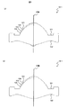
そして、波長変動や温度変化に基づく収差劣化の問題を解決するため、光ピックアップレンズのレンズ面(光学機能面)に、特許文献1の図2に示すようなブレーズ型の回折構造が設計されることがある。一方、特許文献1の図1に示すような回折構造とは異なる輪帯構造が光ピックアップレンズのレンズ面に設計されることもある。レンズ面に回折構造とは異なる輪帯構造が形成された光ピックアップレンズ(以下、非回折輪帯レンズと称する。)を図7に示す。
In order to solve the problem of aberration deterioration due to wavelength variation and temperature change, a blazed diffraction structure as shown in FIG. 2 of
図7に示すように、当該非回折輪帯レンズにおいても、隣り合う輪帯間の段差量は大きく、また、レンズ外縁部においては突起部が形成される。そして、非回折輪帯レンズにおいても、当該輪帯間の段差量や突起部による成形上の問題が生じる場合がある。 As shown in FIG. 7, also in the non-diffractive annular lens, a step amount between adjacent annular zones is large, and a protrusion is formed on the outer edge portion of the lens. Even in the non-diffractive annular zone lens, there may be a problem in molding due to a step amount between the annular zones or a projection.
しかしながら、非回折輪帯レンズにおいて、当該輪帯間の段差量や突起部による成形上の問題を解決することは、回折レンズに比べて非常に難しい。 However, in the non-diffractive annular zone lens, it is very difficult to solve the molding problem due to the difference in level between the annular zones and the protrusion.
ここで、非回折輪帯レンズのレンズ中心からレンズ外縁部に向かって、各輪帯領域を、第1輪帯、第2輪帯、・・・、第N輪帯(Nは正の整数)とする。図7に示すように、当該非回折輪帯レンズにおいて、各輪帯の非球面は、当該輪帯構造が形成されるレンズ面が凸となるような形状となっている。 Here, from the lens center of the non-diffractive annular lens toward the outer edge of the lens, each annular region is defined as the first annular zone, the second annular zone, ..., the Nth annular zone (N is a positive integer). And As shown in FIG. 7, in the non-diffractive annular zone lens, the aspheric surface of each annular zone has a shape such that the lens surface on which the annular zone structure is formed is convex.
また、当該非回折輪帯レンズでは、レンズ中心から所定位置までの範囲では、隣り合う輪帯間に、レンズ中心からレンズ外縁部に向かって、レンズ中心厚が薄くなる方向に段差が形成され、当該所定位置からレンズ外縁部までの範囲では、隣り合う輪帯間に、レンズ中心からレンズ外縁部に向かって、レンズ中心厚が厚くなる方向に段差が形成される。 In the non-diffractive annular zone lens, in the range from the lens center to a predetermined position, a step is formed in the direction in which the lens center thickness decreases from the lens center to the lens outer edge portion, between adjacent zones. In the range from the predetermined position to the lens outer edge, a step is formed between adjacent annular zones in the direction in which the lens center thickness increases from the lens center toward the lens outer edge.
ここで、n輪帯(nは、1≦n≦Nを満たす整数)の非球面をレンズ中心に向かって仮想的に延長した場合、当該非球面とレンズ中心を通る光軸との交点をCn(nは、1≦n≦Nを満たす整数)とする。交点C1と交点Cnとの距離を軸上段差量Dn(nは、1≦n≦Nを満たす整数)とし、光軸に平行で光ディスク側に向かう方向を正の方向とすると、図7に示す非回折輪帯レンズでは、次の(4)式且つ(5)式を満たす第m輪帯を備えている。ただし、mは、1<m<Nを満たす整数である。
|Dm−1|<|Dm| ・・・・・(4)
|Dm|>|Dm+1| ・・・・・(5)
Here, when an aspherical surface of an n ring zone (n is an integer satisfying 1 ≦ n ≦ N) is virtually extended toward the lens center, the intersection of the aspherical surface and the optical axis passing through the lens center is represented by C. n (n is an integer satisfying 1 ≦ n ≦ N). Assuming that the distance between the intersection C 1 and the intersection C n is the axial step amount D n (n is an integer satisfying 1 ≦ n ≦ N), and the direction parallel to the optical axis toward the optical disk side is a positive direction. The non-diffractive annular lens shown in FIG. 7 includes an m-th annular zone that satisfies the following expressions (4) and (5). However, m is an integer satisfying 1 <m <N.
| D m-1 | <| D m | (4)
| D m |> | D m + 1 | (5)
換言すれば、図7に示す非回折輪帯レンズでは、第1輪帯から第m輪帯までの範囲では、隣り合う輪帯間に、レンズ中心からレンズ外縁部に向かって、軸上段差量Dnが増加する方向に段差が形成され、第m輪帯から第N輪帯までの範囲では、隣り合う輪帯間に、レンズ中心からレンズ外縁部に向かって、軸上段差量Dnが減少する方向に段差が形成されている。 In other words, in the non-diffractive annular zone lens shown in FIG. 7, in the range from the first annular zone to the m-th annular zone, the axial step amount from the lens center to the lens outer edge portion between adjacent annular zones. A step is formed in the direction in which D n increases, and in the range from the m-th zone to the N-th zone, the axial step amount D n is between adjacent zones from the lens center to the lens outer edge. A step is formed in the decreasing direction.
すなわち、レンズ中心からレンズ外縁部に向かって、第1輪帯から第m輪帯までの範囲では、隣り合う輪帯間にレンズ中心厚が薄くなる方向に段差が形成され、第m輪帯から第N輪帯までの範囲では、隣り合う輪帯間にレンズ中心厚が厚くなる方向に段差が形成される。つまり、第m輪帯におけるレンズ中厚は最も薄くなるように輪帯構造が形成されている。そこで、以下、当該第m輪帯を谷輪帯と称する。 That is, in the range from the first annular zone to the m-th annular zone from the lens center toward the lens outer edge, a step is formed in the direction in which the lens center thickness becomes thinner between adjacent annular zones, In the range up to the Nth annular zone, a step is formed in the direction in which the lens center thickness increases between adjacent annular zones. That is, the ring zone structure is formed so that the lens middle thickness in the m-th zone is the thinnest. Therefore, hereinafter, the m-th ring zone is referred to as a valley ring zone.
樹脂材料から金型を用いて当該非回折輪帯レンズを形成する場合、金型の当該輪帯間の段差の転写不良が問題となる。ある隣り合う輪帯間において転写不良が生じた場合、当該転写不良に基づいて波面収差が劣化する。また、金型の当該谷輪帯に対応する部分への樹脂材料の充填が不十分になりやすい。さらには、金型の当該谷輪帯よりもレンズ中心側に対応する部分と、当該谷輪帯よりもレンズ外縁側に対応する部分とでは、樹脂の金型への食いつき度合いや、転写不良の向きが異なる。特に、この異なる転写性のつなぎ目となる谷輪帯で転写不良が問題となる。 When the non-diffractive annular lens is formed from a resin material using a mold, a transfer failure of a step between the annular zones of the mold becomes a problem. When a transfer failure occurs between certain adjacent annular zones, the wavefront aberration is degraded based on the transfer failure. In addition, the resin material is likely to be insufficiently filled in the portion corresponding to the valley zone of the mold. Furthermore, the portion of the mold corresponding to the lens center side of the valley ring zone and the portion of the mold corresponding to the lens outer edge side of the valley ring zone, the degree of biting of the resin to the mold, and transfer defects. The direction is different. In particular, transfer failure becomes a problem in the valley zone that becomes a joint between the different transfer properties.
もし、谷輪帯の輪帯領域全体において転写不良が生じた場合、当該転写不良に基づいて球面収差が発生する。また、当該球面収差の次数は、転写不良が生じた谷輪帯の位置によって異なる。また、谷輪帯の輪帯領域の一部において転写不良が生じた場合、当該転写不良に基づいてコマ収差や非点収差が発生する。また、当該コマ収差や非点収差の次数は、転写不良が生じた谷輪帯の位置によって異なる。したがって、谷輪帯を有する非回折輪帯レンズの成形においては、当該輪帯間の段差及び谷輪帯における転写精度を向上することが重要である。 If a transfer failure occurs in the entire annular zone of the valley ring zone, spherical aberration occurs based on the transfer failure. Further, the order of the spherical aberration varies depending on the position of the valley zone where the transfer defect occurs. Further, when a transfer failure occurs in a part of the annular zone of the valley ring zone, coma and astigmatism occur based on the transfer failure. Further, the order of the coma aberration and astigmatism varies depending on the position of the valley zone where the transfer failure occurs. Therefore, in forming a non-diffractive annular zone lens having a valley zone, it is important to improve the step between the zone zones and the transfer accuracy in the valley zone.
樹脂材料から金型を用いてレンズを形成する場合、融解された樹脂が金型に充填されて固められる。そして、樹脂は、金型に充填された時点から金型が冷えるとともに収縮する。この樹脂が収縮する程度は、金型の収縮の程度よりも大きい。そのため、樹脂が収縮した場合、谷輪帯よりレンズ中心側の部分における隣り合う輪帯間の段差部分の樹脂は、金型から外れやすい方向に収縮するが、谷輪帯よりレンズ外縁側の部分における隣り合う輪帯間の段差部分の樹脂は、金型に食いつく方向に収縮する。 When a lens is formed from a resin material using a mold, the molten resin is filled into the mold and hardened. Then, the resin contracts as the mold cools from the time when the resin is filled in the mold. The degree of shrinkage of this resin is greater than the degree of shrinkage of the mold. Therefore, when the resin shrinks, the resin in the stepped portion between adjacent ring zones in the lens center side portion from the valley ring zone shrinks in a direction that is easily detached from the mold, but the portion on the lens outer edge side from the valley ring zone The resin in the stepped portion between adjacent ring zones contracts in the direction to bite into the mold.
そのため、成形後の樹脂が金型から外れにくくなる。そして、谷輪帯よりレンズ中心側の部分と、谷輪帯レンズ外縁側の部分とで、樹脂の金型からの外れにくさに差があることにより、谷輪帯の形状が歪んでしまったり、壊れてしまったりする。つまり、谷輪帯よりレンズ中心側の部分と、谷輪帯レンズ外縁側の部分とで、樹脂の金型からの外れにくさに差があることにより、収差を悪化させてしまう。 Therefore, it becomes difficult for the resin after molding to come off the mold. And, the shape of the valley zone is distorted due to the difference in the difficulty of detachment from the resin mold between the lens center side of the valley zone and the portion on the outer edge side of the valley zone lens. It ’s broken. In other words, the aberration is deteriorated due to the difference in difficulty of the resin from coming off from the mold between the lens center side of the valley zone and the portion on the outer edge side of the valley zone lens.
また、谷輪帯よりレンズ中心側の部分における隣り合う輪帯間の段差部分の樹脂は、金型から外れやすい方向に収縮するため、成形過程の早い段階で金型から外れてしまう場合があり、谷輪帯よりレンズ中心側の部分における転写性が悪くなってしまう場合がある。 Also, the resin at the step between adjacent ring zones in the lens center side of the valley ring zone shrinks in a direction that is easy to come off from the mold, so it may come off the mold early in the molding process. In some cases, the transferability of the portion closer to the center of the lens than the trough is deteriorated.
そこで、金型から樹脂を外す時間を遅らせたり、樹脂に圧力をかけたりする手法がとられる。しかし、一方で、谷輪帯よりもレンズ外縁側の部分における隣り合う輪帯間の段差部分の樹脂は、金型に食いつく方向に収縮するため、金型から樹脂を外す時間を遅らせたり、樹脂に圧力をかけたりすると、谷輪帯よりもレンズ外縁側の部分の樹脂がさらに金型に食いつくこととなる。これにより、谷輪帯における転写性も悪くなってしまう。 Therefore, a method of delaying the time for removing the resin from the mold or applying pressure to the resin is taken. However, on the other hand, the resin in the step portion between adjacent annular zones on the lens outer edge side from the valley annular zone shrinks in the direction to bite into the mold, so the time for removing the resin from the mold is delayed, or the resin If pressure is applied to the lens, the resin on the lens outer edge side of the trough will further bite into the mold. This also deteriorates the transferability in the valley ring zone.
つまり、図7に示す非回折輪帯レンズでは、谷輪帯よりレンズ中心側の部分、谷輪帯、及び谷輪帯よりもレンズ外縁側の部分における転写性が悪くなってしまう。 That is, in the non-diffractive annular zone lens shown in FIG. 7, the transferability at the lens center side portion from the valley zone, the valley zone, and the portion at the lens outer edge side from the valley zone is deteriorated.
さらに、谷輪帯の輪帯幅が狭い場合、谷輪帯における転写性が一層悪化し、収差が悪化してしまう。そして、転写が良好ではないレンズをレーザ光が透過した場合、当該レーザ光は設計どおりの光路を通らず、不要光又は迷光として散乱してしまう。 Furthermore, when the ring zone width of the valley zone is narrow, the transferability in the valley zone is further deteriorated and the aberration is deteriorated. When the laser light is transmitted through a lens with poor transfer, the laser light does not pass through the designed optical path and is scattered as unnecessary light or stray light.
本発明は、このような問題点を解決するためになされたものであり、波長変動や温度変化に基づく収差劣化を防ぐために輪帯構造を設ける際、より精度よく成形できる光ピックアップレンズを提供することを目的とする。 The present invention has been made to solve such problems, and provides an optical pickup lens that can be molded more accurately when an annular structure is provided in order to prevent aberration deterioration based on wavelength fluctuations and temperature changes. For the purpose.
本発明の光ピックアップレンズは、レーザ光を光ディスクに集光する開口数NAが0.8以上の光ピックアップレンズである。また、前記光ピックアップレンズは、レーザ光源側のレンズ面(R1面)及び光ディスク側のレンズ面(R2面)の両面に、前記レンズ面が段差により同心円状の複数の輪帯領域に分割されてなる輪帯構造を備える。 The optical pickup lens of the present invention is an optical pickup lens having a numerical aperture NA of 0.8 or more for condensing laser light on an optical disk. In addition, the optical pickup lens is divided into a plurality of concentric annular zones on a laser light source side lens surface (R1 surface) and an optical disk side lens surface (R2 surface) by steps. An annular zone structure is provided.
また、輪帯数の多い方の面の前記輪帯構造は、レンズ中心からレンズ外縁部に向かって、前記各輪帯領域を、第1輪帯、第2輪帯、・・・、第N輪帯(Nは正の整数)とし、第n輪帯(nは、1≦n≦Nを満たす整数)の非球面を前記レンズ中心に向かって仮想的に延長した場合に、前記非球面と前記レンズ中心を通る光軸との交点をCn(nは、1≦n≦Nを満たす整数)とし、交点C1と交点Cnとの距離を軸上段差量Dnとし、前記光軸に平行で光ディスク側に向かう方向を正の方向とした場合、以下の(4)式且つ(5)式を満たす少なくとも1つの第m輪帯(mは、1<m<Nを満たす整数)を備える。
|Dm−1|<|Dm| ・・・・・(4)
|Dm|>|Dm+1| ・・・・・(5)
In addition, the annular structure on the surface having the larger number of annular zones has the respective annular zones as the first annular zone, the second annular zone,..., Nth, from the lens center toward the lens outer edge. When the aspheric surface of the n-th annular zone (n is an integer satisfying 1 ≦ n ≦ N) is virtually extended toward the lens center, The intersection with the optical axis passing through the center of the lens is C n (n is an integer satisfying 1 ≦ n ≦ N), the distance between the intersection C 1 and the intersection C n is the axial step amount D n , and the optical axis , And the direction toward the optical disk side as a positive direction is at least one m-th zone (m is an integer satisfying 1 <m <N) satisfying the following expressions (4) and (5): Prepare.
| D m-1 | <| D m | (4)
| D m |> | D m + 1 | (5)
また、前記第m輪帯の前記レンズ中心側の境界の半径をRbとし、前記第m輪帯の前記レンズ外縁側の境界の半径をReとし、輪帯幅をRw(=Re−Rs)とし、前記開口数NAが0.85であるときの前記光ピックアップレンズの有効半径をRsとした場合、以下の(6)式を満たすことが好ましい。
Rw/Rs×100≧25(%) ・・・・・(6)
Further, the radius of the boundary on the lens center side of the m-th annular zone is Rb, the radius of the boundary on the lens outer edge side of the m-th annular zone is Re, and the annular zone width is Rw (= Re−Rs). When the effective radius of the optical pickup lens when the numerical aperture NA is 0.85 is Rs, the following expression (6) is preferably satisfied.
Rw / Rs × 100 ≧ 25 (%) (6)
第m輪帯の輪帯幅が狭すぎると、当該第m輪帯に対応する金型部分へ樹脂を十分に充填できなくなり、レンズの収差性能の悪化をもたらす。一方、第m輪帯の輪帯幅(Re−Rb)が、当該光ピックアップレンズの有効半径Rsの25%以上である場合、当該第m輪帯に対応する金型部分へ樹脂を十分に充填することができるだけでなく、金型部分に樹脂を充填する際における樹脂の乱れを防止する。これにより、レンズの収差性能の悪化をより確実に防止する。 If the annular zone width of the m-th annular zone is too narrow, the mold portion corresponding to the m-th annular zone cannot be sufficiently filled with resin, and the aberration performance of the lens is deteriorated. On the other hand, when the zone width (Re-Rb) of the m-th zone is 25% or more of the effective radius Rs of the optical pickup lens, the mold portion corresponding to the m-th zone is sufficiently filled with resin. Not only can this be performed, but also the resin can be prevented from being disturbed when the mold is filled with the resin. This more reliably prevents the deterioration of the aberration performance of the lens.
さらに好ましくは、(16)式を満たすことである。
25≦Rw/Rs×100≦35(%) ・・・・・(16)
逆に、第m輪帯の輪帯幅が広すぎると、当該第m輪帯に対応する金型部分へ樹脂を十分に充填することは容易になるが、前記第m輪帯の波長変動や温度変化に基づく収差劣化を防ぐための輪帯構造を設ける際、隣接段差量を大きくとらなければいけなくなり、成形しづらくなる。ここで、隣接段差量とは、各輪帯領域間の段差の段差量の事である。
More preferably, it is satisfy | filling (16) Formula.
25 ≦ Rw / Rs × 100 ≦ 35 (%) (16)
On the contrary, if the ring width of the m-th ring zone is too wide, it becomes easy to sufficiently fill the mold part corresponding to the m-th ring zone with the resin. When providing an annular structure for preventing aberration deterioration due to temperature change, it is necessary to take a large amount of adjacent steps, which makes it difficult to mold. Here, the adjacent step amount is a step amount of a step between each annular zone region.
さらに好ましくは、(17)式を満たすことである。
27≦Rw/Rs×100≦33(%) ・・・・・(17)
これにより、さらにレンズの収差性能の悪化をより確実に防止する。
More preferably, it is satisfy | filling (17) Formula.
27 ≦ Rw / Rs × 100 ≦ 33 (%) (17)
This further reliably prevents deterioration of the aberration performance of the lens.
本発明の光ピックアップレンズにおいては、Dn>0の場合、Dm−1<Dm且つDm>Dm+1を満たし、又は、Dn<0の場合、Dm−1>Dm且つDm<Dm+1を満たす第m輪帯を少なくとも1つ備えている。換言すれば、Dn>0の場合、第m輪帯よりレンズ中心側の範囲では、レンズ中心からレンズ外縁部に向かって、軸上段差量Dnが増加する方向に段差が形成され、第m輪帯よりレンズ外縁側の範囲では、レンズ中心からレンズ外縁部に向かって、軸上段差量Dnが減少する方向に段差が形成されている。また、Dn<0の場合、第m輪帯よりレンズ中心側の範囲では、レンズ中心からレンズ外縁部に向かって、軸上段差量Dnが減少する方向に段差が形成され、第m輪帯よりレンズ外縁側の範囲では、レンズ中心からレンズ外縁部に向かって、軸上段差量Dnが増加する方向に段差が形成されている。 In the optical pickup lens of the present invention, when D n > 0, D m−1 <D m and D m > D m + 1 is satisfied, or when D n <0, D m−1 > D m and D At least one m-th zone that satisfies m <D m + 1 is provided. In other words, when D n > 0, in the range closer to the lens center than the m-th annular zone, a step is formed in the direction in which the axial step amount D n increases from the lens center to the lens outer edge, In the range on the lens outer edge side from the m ring zone, a step is formed in the direction in which the axial step amount D n decreases from the lens center toward the lens outer edge. Further, when D n <0, a step is formed in the direction in which the axial step amount D n decreases from the lens center toward the lens outer edge in the range closer to the lens center than the m-th ring zone, and the m-th ring In the range on the lens outer edge side from the band, a step is formed in the direction in which the axial step amount D n increases from the lens center toward the lens outer edge.
すなわち、Dn>0の場合、レンズ中心からレンズ外縁部に向かって、第m輪帯よりレンズ中心側の範囲では、隣り合う輪帯間にレンズ中心厚が薄くなる方向に段差が形成され、第m輪帯よりレンズ外縁側の範囲では、隣り合う輪帯間にレンズ中心厚が厚くなる方向に段差が形成されている。また、Dn<0の場合、レンズ中心からレンズ外縁部に向かって、第m輪帯よりレンズ中心側の範囲では、隣り合う輪帯間にレンズ中心厚が厚くなる方向に段差が形成され、第m輪帯よりレンズ外縁側の範囲では、隣り合う輪帯間にレンズ中心厚が薄くなる方向に段差が形成されている。 That is, in the case of D n > 0, a step is formed in the direction in which the lens center thickness becomes thinner between adjacent annular zones in the range closer to the lens center than the m-th annular zone from the lens center toward the lens outer edge. In the range on the lens outer edge side from the m-th annular zone, a step is formed in the direction in which the lens center thickness increases between adjacent annular zones. In the case of D n <0, a step is formed in the direction from the lens center toward the lens outer edge portion in the direction of increasing the lens center thickness between adjacent annular zones in the range closer to the lens center than the m-th annular zone, In the range on the lens outer edge side from the m-th annular zone, a step is formed between adjacent annular zones in a direction in which the lens center thickness becomes thinner.
つまり、Dn>0の場合、第m輪帯におけるレンズ中心厚は最も薄くなるように輪帯構造が形成されており、Dn<0の場合、第m輪帯におけるレンズ中心厚は最も厚くなるように輪帯構造が形成されている。 That is, when D n > 0, the lens zone structure is formed such that the lens center thickness in the m-th zone is the thinnest, and when D n <0, the lens center thickness in the m-th zone is the thickest. An annular structure is formed so as to be.
またさらに、レーザ光源側と反対側のディスク側面にも輪帯構造を備えることにより、各輪帯間を通る光線で所望の位相差を得ようとする事に関して、特に、波長変動や温度変化に基づく収差劣化を防ぐために輪帯構造を設ける際、成形が容易になるような輪帯構造を考慮しても、レーザ側面の輪帯間の隣接段差量は3〜11μm程度としなければならず、レーザ側面の輪帯間の隣接段差量、言い換えればレーザ側面の輪帯間の位相差の負担量を小さくする必然性が高まる。そこで、レーザ側面のみの輪帯だけで前記所望の位相差を得るのではなく、レーザ側面の輪帯とディスク側面の輪帯から前記所望の位相差を得るようにすることで、レーザ側面の輪帯間の位相差の負担量を小さくすることができるのでレーザ側面の輪帯の形成方法が容易になる。 Furthermore, by providing an annular structure on the side of the disk opposite to the laser light source side, it is possible to obtain a desired phase difference with a light beam passing between the annular areas, particularly for wavelength fluctuations and temperature changes. In order to prevent the deterioration of aberration based on the annular zone structure, even if an annular zone structure that facilitates molding is taken into consideration, the adjacent step amount between the annular zones on the laser side must be about 3 to 11 μm. The necessity of reducing the amount of adjacent steps between the laser side annular zones, in other words, the amount of phase difference burden between the laser side annular zones is increased. Therefore, instead of obtaining the desired phase difference only from the ring of the laser side only, the desired phase difference is obtained from the ring of the laser side and the ring of the disk side. Since the burden of the phase difference between the bands can be reduced, the method of forming the ring on the side surface of the laser becomes easy.
具体的には前記軸上段差や隣接段差の深さを浅くすることが可能になったり、後述する接合領域範囲を小さくすることが可能になったりして、成形がより容易な光ピックアップレンズを提供できる。また、レーザ側面の前記輪帯段差の深さを浅くすることが可能になることから、レーザ側面のサグ量を小さくすることが可能になり、レーザ側面の小型化につながり、例えば光ピックアップのフォーカス動作の際に対物レンズが光ピックアップの立ち上げミラーなどの他部品と衝突してしまう可能性を低くすることが可能になる。 Specifically, it is possible to reduce the depth of the on-axis step and the adjacent step, or to reduce the bonding region range described later, and to make an optical pickup lens that is easier to mold. Can be provided. In addition, since the depth of the annular step on the laser side surface can be reduced, the amount of sag on the laser side surface can be reduced, leading to downsizing of the laser side surface. It is possible to reduce the possibility that the objective lens will collide with other parts such as the rising mirror of the optical pickup during operation.
本発明の第1の態様において、前記輪帯数の多い方の面の輪帯構造は、Dn−1>Dnを満たす少なくとも1つの第n−1輪帯と第n輪帯との間に設けられる接合領域と、を備える。 In a first aspect of the present invention, ring-shaped structure of the surface with the larger the number of zones is, D n-1> between at least one of the first n-1 annular and the n zones satisfying D n A joining region provided on the surface.
そして、前記接合領域の面形状は、前記接合領域の面上の実質的に全ての点の前記光軸方向における位置が前記第n−1輪帯の前記レンズ外縁側の境界の前記光軸方向における位置よりも前記光ディスク側となる形状である。 The surface shape of the joining region is such that the positions of substantially all points on the surface of the joining region in the optical axis direction are in the optical axis direction of the boundary on the lens outer edge side of the n-1 ring zone. The shape is closer to the optical disc than the position at.
従来、Dn−1>Dnを満たす第n−1輪帯と第n輪帯との間では、レーザ光源側に凸となる突起部が形成され、当該突起部のため、レンズの成形性が悪くなる。 Conventionally, a projection that protrudes toward the laser light source side is formed between the n-1 zone and the n-th zone that satisfies D n-1 > D n , and the moldability of the lens due to the projection. Becomes worse.
本発明の第1の態様において、当該輪帯構造は、Dn−1>Dnを満たす少なくとも1つの第n−1輪帯と第n輪帯との間に接合領域を備えている。そして、当該接合領域の面形状は、当該接合領域の面上の実質的に全ての点の光軸方向における位置が、第n−1輪帯のレンズ外縁側の境界の光軸方向における位置よりも光ディスク側となる形状となっている。換言すれば、接合領域の面形状は、第n−1輪帯のレンズ外縁側の境界よりもレーザ光源側に突出しない形状となっている。そのため、隣り合う輪帯間に突起部が形成されることによる光ピックアップレンズの形成上の問題が生じにくくなっている。したがって、成型がより容易な光ピックアップレンズを提供できる。 In the first aspect of the present invention, the ring zone structure includes a junction region between at least one n-1 zone and the nth zone that satisfy D n-1 > D n . The surface shape of the junction region is such that the positions in the optical axis direction of substantially all points on the surface of the junction region are more than the positions in the optical axis direction of the boundary on the lens outer edge side of the n-1th annular zone. The shape is also on the optical disc side. In other words, the surface shape of the joining region is a shape that does not protrude to the laser light source side from the boundary on the lens outer edge side of the (n-1) -th zone. Therefore, a problem in forming an optical pickup lens due to the formation of the protrusions between adjacent annular zones is less likely to occur. Therefore, it is possible to provide an optical pickup lens that is easier to mold.
本発明の第2の態様において、前記輪帯数の多い方の面の輪帯構造は、Dn−1>Dnを満たす全ての第n−1輪帯と第n輪帯との間に設けられる接合領域を備える。 In the second aspect of the present invention, the annular zone structure on the surface having the larger number of annular zones is between all the n-1 annular zones and the nth annular zone satisfying D n-1 > D n. It is provided with a joint region to be provided.
そして、前記接合領域の面形状は、前記接合領域の面上の実質的に全ての点の前記光軸方向における位置が前記第n−1輪帯の前記レンズ外縁側の境界の前記光軸方向における位置よりも前記光ディスク側となる形状である。 The surface shape of the joining region is such that the positions of substantially all points on the surface of the joining region in the optical axis direction are in the optical axis direction of the boundary on the lens outer edge side of the n-1 ring zone. The shape is closer to the optical disc than the position at.
また、従来、Dn−1>Dnを満たす第n−1輪帯と第n輪帯との間では、レーザ光源側に凸となる突起部が形成され、当該突起部のため、レンズの成形性が悪くなる。 Further, conventionally, a projection that is convex toward the laser light source side is formed between the n-1 zone and the n-th zone that satisfies D n-1 > D n . The moldability becomes worse.
本発明の第2の態様において、当該輪帯構造は、Dn−1>Dnを満たす全ての第n−1輪帯と第n輪帯との間に接合領域を備えている。そして、当該接合領域の面形状は、当該接合領域の面上の実質的に全ての点の光軸方向における位置が、第n−1輪帯のレンズ外縁側の境界の光軸方向における位置よりも光ディスク側となる形状となっている。 In the second aspect of the present invention, the annular structure includes a junction region between all the n−1 annular zones and the nth annular zone satisfying D n−1 > D n . The surface shape of the junction region is such that the positions in the optical axis direction of substantially all points on the surface of the junction region are more than the positions in the optical axis direction of the boundary on the lens outer edge side of the n-1th annular zone. The shape is also on the optical disc side.
換言すれば、接合領域の面形状は、第n−1輪帯のレンズ外縁側の境界よりもレーザ光源側に突出しない形状となっている。そのため、隣り合う輪帯間に突起部が形成されることによる光ピックアップレンズの形成上の問題が生じないようになっている。したがって、成型がさらに容易な光ピックアップレンズを提供できる。 In other words, the surface shape of the joining region is a shape that does not protrude to the laser light source side from the boundary on the lens outer edge side of the (n-1) -th zone. Therefore, there is no problem in forming the optical pickup lens due to the formation of the protrusions between the adjacent annular zones. Therefore, it is possible to provide an optical pickup lens that is easier to mold.
本発明の第3の態様にかかる光ピックアップレンズは、レーザ光を光ディスクに集光する開口数NAが0.8以上の光ピックアップレンズである。 The optical pickup lens according to the third aspect of the present invention is an optical pickup lens having a numerical aperture NA of 0.8 or more for condensing laser light on an optical disk.
また、前記輪帯数の多い方の面の輪帯構造は、Dn−1>Dnを満たす第n輪帯の前記レンズ中心側の境界のレンズ径方向における位置が、当該光ピックアップレンズの前記レンズ面の接線角が40°以上となる範囲内であるとき、前記第n輪帯と隣り合う第n−1輪帯と前記第n輪帯との間に設けられる接合領域を備える。 Further, the annular structure of the surface having the larger number of annular zones is such that the position in the lens radial direction of the boundary on the lens center side of the n-th annular zone satisfying D n−1 > D n is the position of the optical pickup lens. When the tangent angle of the lens surface is within a range of 40 ° or more, a joining region is provided between the n-1 annular zone adjacent to the nth annular zone and the nth annular zone.
そして、前記接合領域の面形状は、前記接合領域の面上の実質的に全ての点の前記光軸方向における位置が前記第n−1輪帯の前記レンズ外縁側の境界の前記光軸方向における位置よりも前記光ディスク側となる形状である。 The surface shape of the joining region is such that the positions of substantially all points on the surface of the joining region in the optical axis direction are in the optical axis direction of the boundary on the lens outer edge side of the n-1 ring zone. The shape is closer to the optical disc than the position at.
また、従来、Dn−1>Dnを満たす第n−1輪帯と第n輪帯との間では、レーザ光源側に凸となる突起部が形成され、当該突起部のため、レンズの成形性が悪くなる。しかし、当該突起部による成形性の悪化の程度は、レンズの中心部分よりも外縁部分の方が大きい。そして、特に、光ピックアップレンズのレンズ面の接線角度が40°以上となる範囲において、当該突起部による成形性の悪化が生じることが分かった。 Further, conventionally, a projection that is convex toward the laser light source side is formed between the n-1 zone and the n-th zone that satisfies D n-1 > D n . The moldability becomes worse. However, the degree of deterioration of moldability due to the protrusions is greater in the outer edge portion than in the center portion of the lens. And it turned out that the deterioration of the moldability by the said protrusion part arises in the range in which the tangent angle of the lens surface of an optical pick-up lens becomes 40 degrees or more especially.
本発明の第3の態様において、当該輪帯構造は、Dn−1>Dnを満たす第n輪帯のレンズ中心側の境界のレンズ径方向における位置が当該光ピックアップレンズのレンズ面の接線角度が40°以上となる範囲内であるとき、当該第n輪帯と隣り合う第n−1輪帯と当該第n輪帯との間に接合領域を備えている。そして、当該接合領域の面形状は、当該接合領域の面上の実質的に全ての点の光軸方向における位置が、第n−1輪帯のレンズ外縁側の境界の光軸方向における位置よりも光ディスク側となる形状となっている。 In the third aspect of the present invention, in the annular structure, the position in the lens radial direction of the lens center side boundary of the n-th annular zone that satisfies D n−1 > D n is a tangent to the lens surface of the optical pickup lens. When the angle is within a range of 40 ° or more, a junction region is provided between the n-1 annular zone adjacent to the nth annular zone and the nth annular zone. The surface shape of the junction region is such that the positions in the optical axis direction of substantially all points on the surface of the junction region are more than the positions in the optical axis direction of the boundary on the lens outer edge side of the n-1th annular zone. The shape is also on the optical disc side.
換言すれば、接合領域の面形状は、第n−1輪帯のレンズ外縁側の境界よりもレーザ光源側に突出しない形状となっている。そのため、隣り合う輪帯間に突起部が形成されることによる光ピックアップレンズの形成上の問題が生じないようになっている。したがって、成型がさらに容易な光ピックアップレンズを提供できる。 In other words, the surface shape of the joining region is a shape that does not protrude to the laser light source side from the boundary on the lens outer edge side of the (n-1) -th zone. Therefore, there is no problem in forming the optical pickup lens due to the formation of the protrusions between the adjacent annular zones. Therefore, it is possible to provide an optical pickup lens that is easier to mold.
以上のように軸上段差量Dnについての記述をしたが、本発明と同じ、またはほとんど同じレンズ形状は、輪帯構造のレンズにおいては軸上段差量Dnを全く別な値にしても本発明と同じ効果を得ることができる。それは光軸から離れた位置の半径の値でのサグ量として同じサグ量を得るのに違う軸上段差量であっても得ることができてしまうからである。それは後述する面形状を規定する非球面式からも明らかである。 As described above, the on-axis step amount D n has been described. However, in the lens having the same or almost the same shape as the present invention, the on-axis step amount D n can be set to a completely different value in a lens having a zonal structure. The same effect as the present invention can be obtained. This is because different sag amounts on the axis can be obtained to obtain the same sag amount as the sag amount at the position of the radius away from the optical axis. This is also clear from the aspherical surface that defines the surface shape described later.
本発明の光ピックアップレンズは、レーザ光を光ディスクに集光する開口数NAが0.8以上の光ピックアップレンズである。また、前記光ピックアップレンズは、レーザ光源側のレンズ面(R1面)及び光ディスク側のレンズ面(R2面)の両面に、前記レンズ面が段差により同心円状の複数の輪帯領域に分割されてなる輪帯構造を備える。 The optical pickup lens of the present invention is an optical pickup lens having a numerical aperture NA of 0.8 or more for condensing laser light on an optical disk. In addition, the optical pickup lens is divided into a plurality of concentric annular zones on a laser light source side lens surface (R1 surface) and an optical disk side lens surface (R2 surface) by steps. An annular zone structure is provided.
また、輪帯数の多い方の面の輪帯構造は、レンズ中心からレンズ外縁部に向かって、前記各輪帯領域を、第1輪帯、第2輪帯、・・・、第N輪帯(Nは正の整数)とし、第n輪帯(nは、1≦n≦Nを満たす整数)を通る光線と光軸上を通る光線の光路差をEn(λ)とした場合、以下の(7)式且つ(8)式を満たす少なくとも1つの第m輪帯(mは、1<m<Nを満たす整数)を備える。
|Em−1|<|Em| ・・・・・(7)
|Em|>|Em+1| ・・・・・(8)
Further, the ring structure of the surface with the larger number of ring zones is that the ring zones are divided into the first ring zone, the second ring zone,..., The N-th ring from the lens center toward the lens outer edge. When the band (N is a positive integer) and the optical path difference between the light beam passing through the nth annular zone (n is an integer satisfying 1 ≦ n ≦ N) and the light beam passing on the optical axis is E n (λ), It includes at least one m-th annular zone (m is an integer satisfying 1 <m <N) that satisfies the following expressions (7) and (8).
| E m-1 | <| E m | (7)
| E m | >> | E m + 1 | (8)
また、前記接合領域の面形状は、前記光軸に垂直な面から、レーザ光源側から光ディスク側に向かう方向に、角度θ(°)傾く平面形状であることが好ましい。
さらに、以下の(9)式を満たすことが好ましい。
0≦θ≦15 ・・・・・(9)
The surface shape of the bonding region is preferably a planar shape inclined at an angle θ (°) in a direction from the laser light source side to the optical disk side from a surface perpendicular to the optical axis.
Furthermore, it is preferable to satisfy the following expression (9).
0 ≦ θ ≦ 15 (9)
これにより、第n−1輪帯の傾斜角度と接合領域の傾斜角度とを近い角度とすることができる。そして、成形時における第n−1輪帯における収縮方向と接合領域における収縮方向とをできるだけ一致させることができる。そのため、光ピックアップレンズの寸法を精度良く出すための成形条件をより容易に見つけることができるようになる。 Thereby, the inclination angle of the (n-1) -th zone can be made close to the inclination angle of the joining region. Then, the shrinkage direction in the (n-1) -th zone during molding and the shrinkage direction in the joining region can be matched as much as possible. Therefore, it becomes possible to more easily find molding conditions for accurately obtaining the dimensions of the optical pickup lens.
なお、1つの光ピックアップレンズに設けられる複数の接合領域の傾斜角度は、それぞれ、当該接合領域が設けられるレンズ径方向における位置に応じて異なっていてもよい。 Note that the inclination angles of the plurality of bonding regions provided in one optical pickup lens may be different depending on the positions in the lens radial direction where the bonding regions are provided.
また、Dn−1<Dnを満たす全ての第n−1輪帯及び第n輪帯について、前記第n輪帯の軸上段差量Dnと前記第n−1輪帯の軸上段差量Dn−1との差分の絶対値|dn0|を加算して得られる値をαとし、Dn−1>Dnを満たす全ての第n−1輪帯及び第n輪帯について、前記第n輪帯の軸上段差量Dnと前記第n−1輪帯の軸上段差量Dn−1との差分の絶対値|dn0|を加算して得られる値をβとした場合に、以下の(14)式を満たすことが好ましい。
α−β≧0 ・・・・・(14)
Further, D n-1 <all the (n-1) annular in satisfying D n and the n-th annular zone, on-axis step difference D n between the on-axis step difference of the n-1 wheel band of the n-th annular zone A value obtained by adding the absolute value | dn 0 | of the difference from the quantity D n−1 is α, and for all the n−1 zones and the nth zone that satisfy D n−1 > D n , When the value obtained by adding the absolute value | dn 0 | of the difference between the on-axis step amount Dn of the n-th zone and the on-axis step amount D n-1 of the ( n-1) -th zone is β In addition, it is preferable that the following expression (14) is satisfied.
α−β ≧ 0 (14)
接合領域は、光学機能面ではない。そのため、隣り合う輪帯間に上述した接合領域を設けると、その分、光スポットの光量が低下してしまう。ここで、レンズに入射するレーザ光はレンズにおいて吸収されず、レンズ表面における反射はないものとし、光ピックアップレンズのレーザ光源側のレンズ面に輪帯構造が形成され、光ディスク側のレンズ面は連続的な形状を有するとした場合、光スポットの光量比(%)を、以下の(18)式で表すことができる。
光量比(%)=(1−((有効半径内のレンズ面の面積)−(光学機能面以外の面積))/(有効変形内のレンズ面の面積))×100 ・・・・・(18)
The bonding region is not an optical function surface. For this reason, when the above-described joining region is provided between adjacent annular zones, the light amount of the light spot is reduced accordingly. Here, it is assumed that the laser light incident on the lens is not absorbed by the lens and is not reflected on the lens surface, an annular structure is formed on the lens surface on the laser light source side of the optical pickup lens, and the lens surface on the optical disk side is continuous. When it has a typical shape, the light amount ratio (%) of the light spot can be expressed by the following equation (18).
Light intensity ratio (%) = (1 − ((area of lens surface within effective radius) − (area other than optical functional surface)) / (area of lens surface within effective deformation)) × 100 ( 18)
ここで、(18)式における(光学機能面以外の面積)は、全ての接合領域の面積の和に略等しい。したがって、光ピックアップレンズに設けられる接合領域の数をできるだけ少なくすることにより、光スポットの光量を向上することができる。 Here, (area other than the optical functional surface) in the equation (18) is substantially equal to the sum of the areas of all the junction regions. Therefore, the light quantity of the light spot can be improved by reducing the number of joining regions provided in the optical pickup lens as much as possible.
そして、接合領域が設けられる部分は、Dn−1>Dnを満たす第n−1輪帯と第n輪帯との輪帯間である。そのため、接合領域を設けない輪帯間の段差量の累積値を、接合領域を設ける輪帯間の段差量の累積値よりも大きくすることにより、光スポットの光量の向上を図ることができると考えられる。そこで、本発明では、(14)式を満たすことにより、接合領域を設けない輪帯間の段差量の累積値であるαを、接合領域を設ける輪帯間の段差量の累積値であるβ以上とすることができ、光スポットの光量を向上させることができる。 A portion of the junction region is provided is between zones of the D n-1> a n-1 annular satisfying D n and the n zones. Therefore, it is possible to improve the light amount of the light spot by making the cumulative value of the step amount between the annular zones not provided with the joint region larger than the cumulative value of the step amount between the annular zones provided with the joint region. Conceivable. Therefore, in the present invention, by satisfying the expression (14), α, which is a cumulative value of the step amount between the annular zones where the joint region is not provided, is represented by β, which is a cumulative value of the step amount between the annular zones where the joint region is provided. Thus, the light quantity of the light spot can be improved.
一方、レーザーダイオードの波長変化により前記光ピックアップレンズの屈折率が変化し、前記光ピックアップレンズで収束された光スポットの位置が急激に変化する。この変化を軸上色収差(以下、色収差と記述)と言う。光スポットの光量を向上させるために(14)式を満たす構成をとると、色収差が劣化してしまい、前記光ピックアップレンズを使用した際に、光ディスクでの記録再生が出来なくなったり、フォーカス制御が外れてしまう事が生じてしまう。 On the other hand, the refractive index of the optical pickup lens changes due to the wavelength change of the laser diode, and the position of the light spot converged by the optical pickup lens changes abruptly. This change is called axial chromatic aberration (hereinafter referred to as chromatic aberration). In order to improve the light quantity of the light spot, if the configuration satisfying the equation (14) is adopted, chromatic aberration is deteriorated, and when the optical pickup lens is used, recording / reproduction on the optical disc cannot be performed, or focus control is performed. It comes off.
換言すれば、色収差の劣化を防ぐためには、以下の(19)式を満たすことが好ましい。
α−β≦0 ・・・・・(19)
In other words, in order to prevent deterioration of chromatic aberration, it is preferable to satisfy the following expression (19).
α−β ≦ 0 (19)
よって、光スポットの光量と色収差のバランスをとるためには、以下の(15)式を満たすことが好ましい。
0.8≦α/β≦1.2 ・・・・・(15)
Therefore, in order to balance the light amount of the light spot and the chromatic aberration, it is preferable to satisfy the following expression (15).
0.8 ≦ α / β ≦ 1.2 (15)
また、前記光ピックアップレンズは、波長395nm以上415nm以下の範囲の波長のレーザ光を前記光ディスクに集光することが好ましい。
これにより、BDに対して良好に光スポットを形成する光ピックアップレンズを提供できる。BDの使用波長は405nmであるが、レーザ光源の製造バラツキを考慮して、本発明の光ピックアップレンズの使用波長の範囲を波長395nm以上415nm以下とした。
The optical pickup lens preferably focuses laser light having a wavelength in the range of 395 nm to 415 nm on the optical disc.
Thereby, it is possible to provide an optical pickup lens that forms a light spot favorably with respect to the BD. The operating wavelength of the BD is 405 nm, but considering the manufacturing variation of the laser light source, the operating wavelength range of the optical pickup lens of the present invention is set to the wavelength of 395 nm or more and 415 nm or less.
さらに、前記光ピックアップレンズのレーザ光源側のレンズ面(R1面)及び光ディスク側のレンズ面(R2面)の複数の前記段差は、設計波長及び設計温度時における入射光の位相が輪帯領域相互に波長の略整数倍で異なる段差量であることが好ましい。これにより、周囲温度が変化した場合に前記光ピックアップ対物レンズにおいて発生する収差を低減するような位相差を光束に発生させる段差量を有することができる。 Further, the plurality of steps on the lens surface (R1 surface) on the laser light source side and the lens surface (R2 surface) on the optical disk side of the optical pickup lens are such that the phase of incident light at the design wavelength and design temperature is in the mutual zone region. It is preferable that the difference in level is approximately an integral multiple of the wavelength. As a result, it is possible to have a step amount that causes the light flux to generate a phase difference that reduces the aberration that occurs in the optical pickup objective lens when the ambient temperature changes.
また、第n輪帯(2≦n≦m)と前記第n−1輪帯の隣接段差量の絶対値を|dn|(mm)、波長をλ(mm)、前記光ピックアップ対物レンズの屈折率をNとした場合に、以下の(10)式を満たすことが好ましい。
3≦(N−1)×|dn|/λ≦15 ・・・・・・(10)
In addition, the absolute value of the adjacent step amount between the n-th annular zone (2 ≦ n ≦ m) and the n−1-th annular zone is | dn | (mm), the wavelength is λ (mm), and the optical pickup objective lens is refracted. When the rate is N, it is preferable to satisfy the following expression (10).
3 ≦ (N−1) × | dn | / λ ≦ 15 (10)
換言すれば、隣接段差量×(屈折率−1)が、設計波長の3倍以上15倍以下であることが好ましい。隣接段差量×(屈折率−1)が設計波長の3倍未満である場合、収差を十分補正するためには、光ピックアップ対物レンズに形成する輪帯領域の数を増やす必要がある。そのため、光利用効率が低下してしまう。一方、隣接段差量×(屈折率−1)が設計波長の15倍より大きい場合、段差量が大きくなるため、光ピックアップ対物レンズの製造が困難となる。従って、(10)式を満たすように段差を形成することにより、光利用効率の低下を防止するとともに、光ピックアップ対物レンズの製造を容易にすることができる。 In other words, the adjacent step amount × (refractive index−1) is preferably 3 to 15 times the design wavelength. When the adjacent step amount × (refractive index−1) is less than three times the design wavelength, it is necessary to increase the number of annular regions formed in the optical pickup objective lens in order to sufficiently correct the aberration. For this reason, the light utilization efficiency is lowered. On the other hand, when the adjacent step amount × (refractive index-1) is larger than 15 times the design wavelength, the step amount becomes large, and it becomes difficult to manufacture the optical pickup objective lens. Therefore, by forming the step so as to satisfy the expression (10), it is possible to prevent the light use efficiency from being lowered and to easily manufacture the optical pickup objective lens.
また、前記第n輪帯(2≦n≦N)の軸上段差量Dnと前記第n−1輪帯の軸上段差量Dn−1との差分の絶対値を|dn0|(mm)、波長をλ(mm)、前記光ピックアップ対物レンズの屈折率をNとした場合に、以下の(11)式を満たすことが好ましい。
3≦(N−1)×|dn0|/λ≦12 ・・・・・・(11)
Further, the absolute value of the difference between on-axis step difference D n-1 of the n-th annular zone on-axis step difference amount D n and the (n-1) th wheel band (2 ≦ n ≦ N) | dn 0 | ( mm), the wavelength is λ (mm), and the refractive index of the optical pickup objective lens is N, it is preferable that the following expression (11) is satisfied.
3 ≦ (N−1) × | dn 0 | / λ ≦ 12 (11)
換言すれば、前記第n輪帯軸上段差量Dnと前記第n−1輪帯の軸上段差量Dn−1との差分の絶対値|dn0|×(屈折率−1)が、設計波長の3倍以上12倍以下であることが好ましい。|dn0|×(屈折率−1)が設計波長の3倍未満である場合、収差を十分補正するためには、光ピックアップ対物レンズに形成する輪帯領域の数を増やす必要がある。そのため、光利用効率が低下してしまう。一方、|dn0|×(屈折率−1)が設計波長の12倍より大きい場合、段差量が大きくなるため、光ピックアップ対物レンズの製造が困難となる。従って、(11)式を満たすように段差を形成することにより、光利用効率の低下を防止するとともに、光ピックアップ対物レンズの製造を容易にすることができる。 In other words, the absolute value | dn 0 | × (refractive index−1) of the difference between the n- th annular zone axial step amount D n and the n−1-th annular zone axial step amount D n−1 is obtained. The wavelength is preferably 3 to 12 times the design wavelength. When | dn 0 | × (refractive index−1) is less than three times the design wavelength, it is necessary to increase the number of annular zones formed in the optical pickup objective lens in order to sufficiently correct the aberration. For this reason, the light utilization efficiency is lowered. On the other hand, when | dn 0 | × (refractive index-1) is larger than 12 times the design wavelength, the amount of the step becomes large, making it difficult to manufacture the optical pickup objective lens. Therefore, by forming the step so as to satisfy the expression (11), it is possible to prevent the light use efficiency from being lowered and to easily manufacture the optical pickup objective lens.
また、第n輪帯(2≦n≦m)の隣接段差量の絶対値の累積値Σ|d|の最大値をΣ|d|max、と累積値Σ|d|の最小値をΣ|d|minとした場合に、前記隣接段差量の累積値Σ|d|の最大値Σ|d|maxと最小値Σ|d|minとの差が10λ以上、40λ以下であることが好ましい。 Also, the maximum value of the cumulative value Σ | d | of the absolute value of the adjacent step amount in the n-th annular zone (2 ≦ n ≦ m) is Σ | d | max, and the minimum value of the cumulative value Σ | d | is Σ | When d | min, the difference between the maximum value Σ | d | max and the minimum value Σ | d | min of the cumulative value Σ | d | of the adjacent step amount is preferably 10λ or more and 40λ or less.
隣接段差量の累積値Σ|d|の最大値Σ|d|maxと最小値Σ|d|minとの差が10λ未満の場合、周囲温度の変化によって生じる波面収差を十分に低減することが難しくなる。 When the difference between the maximum value Σ | d | max and the minimum value Σ | d | min of the cumulative value Σ | d | of the adjacent step amount is less than 10λ, the wavefront aberration caused by the change in the ambient temperature can be sufficiently reduced. It becomes difficult.
一方、隣接段差量の累積値Σ|d|の最大値Σ|d|maxと最小値Σ|d|minとの差が40λより大きい場合、周囲温度の変化によって生じる波面収差を過剰に補正してしまうため、かえって、波面収差が劣化してしまう。また、段差量が大きくなってしまい、光ピックアップ対物レンズの製造が困難となる。 On the other hand, if the difference between the maximum value Σ | d | max and the minimum value Σ | d | min of the cumulative value Σ | d | of the adjacent step amount is larger than 40λ, the wavefront aberration caused by the change in the ambient temperature is excessively corrected. On the contrary, the wavefront aberration is deteriorated. In addition, the amount of step becomes large, making it difficult to manufacture the optical pickup objective lens.
また、前記輪帯数の多い方の面の段差の軸上段差量をd0(mm)とした場合、前記軸上段差量Dnの最大値Dmaxと最小値Dminとの差が10λ以上、40λ以下であることが好ましい。 Further, when the axial step amount of the step on the surface with the larger number of ring zones is d 0 (mm), the difference between the maximum value Dmax and the minimum value Dmin of the axial step amount D n is 10λ or more, It is preferable that it is 40λ or less.
軸上段差量Dnの最大値Dmaxと最小値Dminとの差が10λ未満の場合、周囲温度の変化によって生じる波面収差を十分に低減することが難しくなる。一方、軸上段差量Dnの最大値Dmaxと最小値Dminとの差が40λより大きい場合、周囲温度の変化によって生じる波面収差を過剰に補正してしまうため、かえって、波面収差が劣化してしまう。また、段差量が大きくなってしまい、光ピックアップ対物レンズの製造が困難となる。 If the difference between the maximum value Dmax and minimum value Dmin of the axial step difference D n of less than 10 [lambda], it is difficult to sufficiently reduce the wavefront aberration occurring due to a change in ambient temperature. On the other hand, if the difference between the maximum value Dmax and minimum value Dmin of the axial step difference D n is larger than 40Ramuda, since from excessively corrected wavefront aberration caused by changes in ambient temperature, rather, the wavefront aberration is deteriorated End up. In addition, the amount of step becomes large, making it difficult to manufacture the optical pickup objective lens.
また、前記開口数NAが0.85であるときの有効半径Rsは、前記光ピックアップレンズが搭載されるアクチュエータの開口半径と実質的に等しいことが好ましい。 Further, it is preferable that the effective radius Rs when the numerical aperture NA is 0.85 is substantially equal to the opening radius of the actuator on which the optical pickup lens is mounted.
実際には、光ピックアップレンズが取り付けられるアクチュエータはプラスチック製であるため、アクチュエータの開口半径は製品毎で異なる。本発明では、光ピックアップレンズの開口数NAが0.85であるときの有効半径Rsは、当該アクチュエータの開口半径と実質的に等しいため、アクチュエータの開口半径を反映して、第m輪帯の輪帯幅を規定することができる。 Actually, since the actuator to which the optical pickup lens is attached is made of plastic, the opening radius of the actuator varies from product to product. In the present invention, since the effective radius Rs when the numerical aperture NA of the optical pickup lens is 0.85 is substantially equal to the aperture radius of the actuator, the aperture radius of the actuator reflects the aperture radius of the actuator. The zone width can be defined.
さらに、前記光ピックアップレンズは、樹脂材料、又は、樹脂材料に無機材料若しくは主に無機材料からなる材料を分散させた材料から成形されることが好ましい。また、前記光ピックアップレンズは、ガラス材料から成形されることが好ましい。
これにより、一般的なレンズ材料から第1の態様乃至第3の態様の何れかと同様の効果を奏する光ピックアップレンズを製造することができる。
Further, the optical pickup lens is preferably molded from a resin material or a material obtained by dispersing an inorganic material or a material mainly composed of an inorganic material in the resin material. The optical pickup lens is preferably molded from a glass material.
Thereby, an optical pickup lens having the same effects as any of the first to third aspects can be manufactured from a general lens material.
また、前記光ピックアップレンズは、BD用のピックアップに搭載されることが好ましい。 The optical pickup lens is preferably mounted on a BD pickup.
本発明によれば、波長変動や温度変化に基づく収差劣化を防ぐために輪帯構造を設ける際、より精度よく成形できる光ピックアップレンズを提供することができる。 According to the present invention, it is possible to provide an optical pickup lens that can be molded with higher accuracy when an annular structure is provided in order to prevent aberration deterioration based on wavelength variation or temperature change.
以下、本発明を適用した具体的な実施の形態について、図面を参照しながら詳細に説明する。なお、本発明は、以下の実施の形態に限定されるものではない。図1は、本発明の実施の形態にかかる光ピックアップ光学系1の一例を示したものである。本実施形態にかかる光ピックアップ光学系1は、本発明にかかる光ピックアップ装置又は光ディスク装置に用いられる。
Hereinafter, specific embodiments to which the present invention is applied will be described in detail with reference to the drawings. Note that the present invention is not limited to the following embodiments. FIG. 1 shows an example of an optical pickup
光ピックアップ光学系1は、光源11(レーザ光源)、ビームスプリッタ12、コリメータレンズ13、ピックアップレンズ14(光ピックアップ対物レンズ)、検出系16等を備えている。なお、本実施形態では、光ディスク15としてBD(ブルーレイディスク)を用いた。
The optical pickup
光源11は、BD用に用いられる青色レーザーダイオード等を備えている。光源11から出射されたレーザ光(光束)の光路上にビームスプリッタ12が設けられている。
The
ビームスプリッタ12より出射したレーザ光の光路上にコリメータレンズ13が設けられている。コリメータレンズ13は、ビームスプリッタ12から出射されたレーザ光の発散度合いを調整して、当該レーザ光を出射する。
A
コリメータレンズ13を透過したレーザ光の光路上にピックアップレンズ14が設けられている。
A
ピックアップレンズ14は、入射された光を光ディスク(BD)15の情報記録面に集光させる機能を有する。BDには、記録層を1層のみ有する単層BDと、記録層を複数層有する多層BDとが知られている。単層BDの透明基板厚は0.100mmである。また、記録層を2層有する2層BDの各記録層の透明基板厚は、0.075mmと、0.100mmである。
The
ピックアップレンズ14が2層BDの記録層にレーザ光を集光する場合、各記録層間の基板厚差0.025mmによって、約0.25λrmsの大きな球面収差が発生してしまう。そこで、通常、コリメータレンズ13を光軸に沿って移動させることにより、ピックアップレンズ14に入射する光束の発散度合いを調整することにより、当該球面収差を補正する。
When the
ここで、コリメータレンズ13を光軸に沿って移動させることによって補正するという事は、ピックアップレンズ14に入射するレーザ光の発散度合いを調整する事である。これは、ピックアップレンズ14に入射する光の仮想的な発行点位置(物点の位置)を調整し、仮想的な発行点位置からコリメータレンズ13を介さずにピックアップレンズ14入射させる事と等価である。換言すれば、ピックアップレンズ14の物体距離を調整することにより、当該球面収差を補正する。
Here, the correction by moving the
そこで、本発明の実施の形態にかかるピックアップレンズ14は、2層BDにおける各記録層の透明基板厚(0.075mm、0.100mm)の中間の透明基板厚である0.0875mmに良好に集光するように設計されている。これにより、前述の方法を用いる事により、各記録層間の透明基板厚(0.075mm、0.100mm)においても、基板厚差によって生じる球面収差を低減することができる。
Therefore, the
よって、発明の実施の形態にかかるピックアップレンズ14が使用可能な透明基板厚は、本実施例で設計されている0.0875mmに限られるものではない。
なお、本実施の形態では、光ディスク15の透明基板はポリカーボネイト(PC)とした。
Therefore, the thickness of the transparent substrate that can be used by the
In the present embodiment, the transparent substrate of the
ピックアップレンズ14は、さらに、光ディスク15の情報記録面で反射されたレーザ光を検出系16に導く機能も有する。
The
また、ピックアップレンズ14のレーザ光源側のレンズ面(R1面)及び光ディスク側のレンズ面(R2面)の両面には、ピックアップレンズ14の光軸を同心とする複数の輪帯領域が形成されている。また、隣り合う輪帯領域間には段差が形成されている。
In addition, a plurality of annular zones that are concentric with the optical axis of the
換言すれば、ピックアップレンズ14の少なくとも一方の面は、複数の段差により、ピックアップレンズ14の光軸を同心とする複数の輪帯領域に分割されている。また、ピックアップレンズ14は、プラスチック素材から形成されている。
In other words, at least one surface of the
ピックアップレンズ14のレーザ光源側のレンズ面(R1面)及び光ディスク側のレンズ面(R2面)両面に形成された複数の段差の段差量は、設計波長及び設計温度時(レーザ光の波長が設計波長であり、周囲温度が設計温度であるとき)に入射したレーザ光の位相が隣接する輪帯領域相互に波長の略整数倍で異なるように設定されている。
The steps of the plurality of steps formed on both the laser light source side lens surface (R1 surface) and the optical disk side lens surface (R2 surface) of the
また、ピックアップレンズ14に形成された複数の段差は、周囲温度が変化することによって発生する収差を低減するようにレーザ光に位相差を発生させる段差量を有する。
ここで、波長の略整数倍とは、波長の(整数)×0.999倍〜波長の(整数)×1.001倍であることが好ましい。
Further, the plurality of steps formed on the
Here, the substantially integer multiple of the wavelength is preferably (integer) × 0.999 times the wavelength to (integer) × 1.001 times the wavelength.
たとえば、本実施の形態において、波長の略10倍とは、10×0.999=9.99、10×1.001=10.01より、波長の9.99倍〜10.01倍を意味する。なお、波長の略整数倍とは、波長の(整数)×0.995倍〜波長の(整数)×1.005倍であってもよい。この場合においても、ピックアップレンズ14に形成された段差により、周囲温度が変化した場合に発生する波面収差を十分に低減することができる。
For example, in this embodiment, approximately 10 times the wavelength means 9.99 times to 10.01 times the wavelength from 10 × 0.999 = 9.99, 10 × 1.001 = 10.01. To do. The substantially integer multiple of the wavelength may be (integer) × 0.995 times the wavelength to (integer) × 1.005 times the wavelength. Even in this case, the wavefront aberration generated when the ambient temperature changes can be sufficiently reduced by the step formed on the
フォーカスサーボ時、及びトラッキングサーボ時には、ピックアップレンズ14が図示されないアクチュエータにより動作する。
At the time of focus servo and tracking servo, the
次に、光源11から出射されたレーザ光が光ディスク15の情報記録面で反射され検出系16に検出されるまでの挙動について説明する。光源11から出射されたレーザ光はビームスプリッタ12を透過してコリメータレンズ13に入射する。
Next, the behavior until the laser beam emitted from the
コリメータレンズ13は、ビームスプリッタ12から出射されたレーザ光の発散度合いを調整して、当該レーザ光を出射する。
The
コリメータレンズ13を透過したレーザ光はピックアップレンズ14に入射される。ここで、本実施の形態においては、周囲温度が変化した場合、このピックアップレンズ14に設けられた複数の段差は、周囲温度の変化によって発生する収差を低減するようにレーザ光の位相を補正する。
The laser light that has passed through the
そして、ピックアップレンズ14は、補正後のレーザ光を光ディスク15の情報記録面に集光させる。光ディスク15の情報記録面で反射されたレーザ光は、ピックアップレンズ14を介して検出系16に入射し、検出される。検出系16は、当該レーザ光を検出し、光電変換することによって、フォーカスサーボ信号、トラックサーボ信号、再生信号などを生成する。
Then, the
本実施の形態にかかる光ピックアップレンズは、BD(ブルーレイディスク)の情報記録面に対して、波長395nm〜415nmの範囲内の波長のレーザ光を集光させる。また、本実施の形態にかかる光ピックアップレンズの開口数NAは0.8以上である。 The optical pickup lens according to the present embodiment condenses laser light having a wavelength in the range of 395 nm to 415 nm on an information recording surface of a BD (Blu-ray disc). The numerical aperture NA of the optical pickup lens according to the present embodiment is 0.8 or more.
また、本発明にかかる光ピックアップレンズは、レーザ光源側のレンズ面(R1面)及び光ディスク側のレンズ面(R2面)両面に、当該レンズ面が段差により同心円状の複数の輪帯領域に分割されてなる輪帯構造を備えている。換言すれば、本発明にかかる光ピックアップレンズのレーザ光源側のレンズ面(R1面)及び光ディスク側のレンズ面(R2面)両面は、同心円状に、複数の輪帯領域に分割されており、隣り合う輪帯領域の間には段差が形成されている。 Further, the optical pickup lens according to the present invention is divided into a plurality of concentric annular zones on the lens surface (R1 surface) on the laser light source side and the lens surface (R2 surface) on the optical disk side by steps. An annular zone structure is provided. In other words, both the laser light source side lens surface (R1 surface) and the optical disk side lens surface (R2 surface) of the optical pickup lens according to the present invention are concentrically divided into a plurality of annular zones, A step is formed between adjacent annular zones.
次に、本発明の実施の形態にかかる光ピックアップ光学系1において用いられる光ピックアップレンズ14について詳細に説明する。
Next, the
図2は、本実施の形態にかかる光ピックアップ光学系1における光ピックアップレンズ14を示す図である。図2の(a)は、設計波長及び設計温度時におけるレーザ光の波面(位相)を示し、図2の(b)は、周囲温度が設計温度より低くなりレーザ光の波長が設計波長より短くなった場合におけるレーザ光の波面(位相)を示し、図2の(c)は、周囲温度が設計温度より高くなりレーザ光の波長が設計波長より長くなった場合におけるレーザ光の波面(位相)を示している。本実施形態では、光ピックアップレンズ14の光源11側の面に、上述した複数の段差を設ける。
FIG. 2 is a diagram showing the
そして、複数の段差の段差量は、透過したレーザ光の位相が隣接する輪帯領域相互に波長の略整数倍で異なるように設定されている。また、光ピックアップレンズ14の段差は、周囲温度が変化した場合に周囲温度の変化によって生じる収差を低減するようにレーザ光に位相差を発生させる段差量を有する。
The step amounts of the plurality of steps are set so that the phases of the transmitted laser light are different from each other between the adjacent annular zones by approximately an integral multiple of the wavelength. Further, the step of the
すなわち、設計波長及び設計温度時にレーザ光が光ピックアップレンズ14に入射する場合、各輪帯領域を透過したレーザ光の位相は相互に波長の整数倍だけ異なる。従って、図2(a)に示されるように、設計波長及び設計温度時には、異なる輪帯領域を透過したレーザ光には位相差が発生しない。そのため、光ピックアップレンズ14に入射したレーザ光は、同一位相のまま、出射する。従って、設計波長及び設計温度時において、光ピックアップレンズ14により集光されるレーザ光の収差は段差が形成されていない場合と同じとなる。
That is, when the laser light is incident on the
他方、図2の(b)、(c)に示されるように、周囲温度が変化し、波長が変化したレーザ光が光ピックアップレンズ14に入射する場合、各輪帯領域を透過したレーザ光の位相の違いは波長の整数倍とならない。従って、図2の(b)、(c)に示されるように、波長が変化した場合には、異なる輪帯領域を透過したレーザ光に位相差が発生する。
On the other hand, as shown in FIGS. 2B and 2C, when the ambient temperature changes and the laser light whose wavelength has changed is incident on the
そして、本発明においては、当該位相差は、周囲温度の変化によって発生する収差を低減するような大きさとなっている。そのため、周囲温度が変化した場合、従来では光ピックアップレンズにより集光される収差が増大してしまうが、本発明においては、光ピックアップレンズ14の各輪帯領域を透過したレーザ光の位相差により、周囲温度の変化に伴う収差の増大が抑制される。そして、光ピックアップレンズ14より出射したレーザ光は、光ディスク15の情報記録面に良好に集光する。
In the present invention, the phase difference is sized so as to reduce aberrations caused by changes in ambient temperature. For this reason, when the ambient temperature changes, conventionally, aberrations collected by the optical pickup lens increase. However, in the present invention, due to the phase difference of the laser light transmitted through each annular zone of the
また、当該輪帯構造は、レンズ中心からレンズ外縁部に向かって、各輪帯領域を、第1輪帯、第2輪帯、・・・、第N輪帯(Nは正の整数)とし、第n輪帯(nは、1≦n≦Nを満たす整数)の非球面をレンズ中心に向かって仮想的に延長した場合に、非球面とレンズ中心を通る光軸との交点をCn(nは、1≦n≦Nを満たす整数)とし、交点C1と交点Cnとの距離を軸上段差量Dnとし、光軸に平行で光ディスク側に向かう方向(レーザ光源から光ディスクに向かう方向)を正の方向とした場合、以下の(4)式且つ(5)式を満たす少なくとも1つの第m輪帯(mは、1<m<Nを満たす整数)を備えている。
|Dm−1|<|Dm| ・・・・・(4)
|Dm|>|Dm+1| ・・・・・(5)
In the annular structure, each annular region is defined as a first annular zone, a second annular zone, ..., an Nth annular zone (N is a positive integer) from the lens center toward the lens outer edge. When the aspherical surface of the n-th annular zone (n is an integer satisfying 1 ≦ n ≦ N) is virtually extended toward the lens center, the intersection of the aspherical surface and the optical axis passing through the lens center is defined as C n (N is an integer satisfying 1 ≦ n ≦ N), and the distance between the intersection C 1 and the intersection C n is the axial step amount D n, and is parallel to the optical axis toward the optical disc (from the laser light source to the optical disc). When the positive direction is a positive direction, at least one m-th zone (m is an integer satisfying 1 <m <N) satisfying the following expressions (4) and (5) is provided.
| D m-1 | <| D m | (4)
| D m |> | D m + 1 | (5)
つまり、輪帯構造は、Dn>0の場合、Dm−1<Dm且つDm>Dm+1を満たし、又は、Dn<0の場合、Dm−1>Dm且つDm<Dm+1を満たす第m輪帯を少なくとも1つ備えている。換言すれば、Dn>0の場合、第m輪帯よりレンズ中心側の範囲では、レンズ中心からレンズ外縁部に向かって、軸上段差量Dnが増加する方向に段差が形成され、第m輪帯よりレンズ外縁側の範囲では、レンズ中心からレンズ外縁部に向かって、軸上段差量Dnが減少する方向に段差が形成されている。 That is, the ring zone structure satisfies D m−1 <D m and D m > D m + 1 when D n > 0, or D m−1 > D m and D m <when D n <0. At least one m-th zone that satisfies D m + 1 is provided. In other words, when D n > 0, in the range closer to the lens center than the m-th zone, a step is formed in the direction in which the axial step amount Dn increases from the lens center toward the lens outer edge, and the m th In the range on the lens outer edge side from the annular zone, a step is formed in the direction in which the axial step amount D n decreases from the lens center toward the lens outer edge.
また、Dn<0の場合、第m輪帯よりレンズ中心側の範囲では、レンズ中心からレンズ外縁部に向かって、軸上段差量Dnが減少する方向に段差が形成され、第m輪帯よりレンズ外縁側の範囲では、レンズ中心からレンズ外縁部に向かって、軸上段差量Dnが増加する方向に段差が形成されている。 Further, when D n <0, a step is formed in the direction in which the axial step amount D n decreases from the lens center toward the lens outer edge in the range closer to the lens center than the m-th ring zone, and the m-th ring In the range on the lens outer edge side from the band, a step is formed in the direction in which the axial step amount D n increases from the lens center toward the lens outer edge.
すなわち、Dn>0の場合、レンズ中心からレンズ外縁部に向かって、第m輪帯よりレンズ中心側の範囲では、隣り合う輪帯間にレンズ中心厚が薄くなる方向に段差が形成され、第m輪帯よりレンズ外縁側の範囲では、隣り合う輪帯間にレンズ中心厚が厚くなる方向に段差が形成されている。 That is, in the case of D n > 0, a step is formed in the direction in which the lens center thickness becomes thinner between adjacent annular zones in the range closer to the lens center than the m-th annular zone from the lens center toward the lens outer edge. In the range on the lens outer edge side from the m-th annular zone, a step is formed in the direction in which the lens center thickness increases between adjacent annular zones.
また、Dn<0の場合、レンズ中心からレンズ外縁部に向かって、第m輪帯よりレンズ中心側の範囲では、隣り合う輪帯間にレンズ中心厚が厚くなる方向に段差が形成され、第m輪帯よりレンズ外縁側の範囲では、隣り合う輪帯間にレンズ中心厚が薄くなる方向に段差が形成されている。つまり、Dn>0の場合、第m輪帯におけるレンズ中心厚は最も薄くなるように輪帯構造が形成されており、Dn<0の場合、第m輪帯におけるレンズ中心厚は最も厚くなるように輪帯構造が形成されている。 In the case of D n <0, a step is formed in the direction from the lens center toward the lens outer edge portion in the direction of increasing the lens center thickness between adjacent annular zones in the range closer to the lens center than the m-th annular zone, In the range on the lens outer edge side from the m-th annular zone, a step is formed between adjacent annular zones in a direction in which the lens center thickness becomes thinner. That is, when D n > 0, the lens zone structure is formed such that the lens center thickness in the m-th zone is the thinnest, and when D n <0, the lens center thickness in the m-th zone is the thickest. An annular structure is formed so as to be.
また、輪帯構造は、Dn−1>Dnを満たす少なくとも1つの第n−1輪帯と第n輪帯との間に設けられる接合領域を備えている。 The annular structure includes a junction region provided between at least one n-1 annular zone and the nth annular zone that satisfies D n-1 > D n .
そして、当該接合領域の面形状は、接合領域の面上の実質的に全ての点の光軸方向における位置が当該第n−1輪帯のレンズ外縁側の境界の光軸方向における位置よりも光ディスク側となる形状となっている。 And the surface shape of the said joining area | region is that the position in the optical axis direction of the substantially all points on the surface of a joining area | region is rather than the position in the optical axis direction of the boundary of the lens outer edge side of the said n-1 ring zone. The shape is on the optical disc side.
従来、Dn−1>Dnを満たす第n−1輪帯と第n輪帯との間では、レーザ光源側に凸となる突起部が形成され、当該突起部のため、レンズの成形性が悪くなる。本実施の形態にかかる光ピックアップレンズにおいては、当該輪帯構造において、Dn−1>Dnを満たす少なくとも1つの第n−1輪帯と第n輪帯との間に接合領域を備えている。そして、当該接合領域の面形状は、当該接合領域の面上の実質的に全ての点の光軸方向における位置が、第n−1輪帯のレンズ外縁側の境界の光軸方向における位置よりも光ディスク側となる形状となっている。 Conventionally, a projection that protrudes toward the laser light source side is formed between the n-1 zone and the n-th zone that satisfies D n-1 > D n , and the moldability of the lens due to the projection. Becomes worse. In the optical pickup lens according to the present embodiment, in the annular structure, a junction region is provided between at least one n-1 annular zone and the nth annular zone satisfying D n-1 > D n. Yes. The surface shape of the junction region is such that the positions in the optical axis direction of substantially all points on the surface of the junction region are more than the positions in the optical axis direction of the boundary on the lens outer edge side of the n-1th annular zone. The shape is also on the optical disc side.
換言すれば、接合領域の面形状は、第n−1輪帯のレンズ外縁側の境界よりもレーザ光源側に突出しない形状となっている。そのため、隣り合う輪帯間に突起部が形成されることによる光ピックアップレンズの形成上の問題が生じにくくなっている。したがって、成型がより容易な光ピックアップレンズを提供できる。 In other words, the surface shape of the joining region is a shape that does not protrude to the laser light source side from the boundary on the lens outer edge side of the (n-1) -th zone. Therefore, a problem in forming an optical pickup lens due to the formation of the protrusions between adjacent annular zones is less likely to occur. Therefore, it is possible to provide an optical pickup lens that is easier to mold.
本発明の実施の形態にかかる光ピックアップレンズの一例を図3の(a)に示す。図3の(a)に示す光ピックアップレンズ14−1において、レーザ光源側のレンズ面101に、輪帯構造が形成されている。また、光ピックアップレンズ14の光ディスク側のレンズ面102にも、輪帯構造が形成されている。
An example of the optical pickup lens according to the embodiment of the present invention is shown in FIG. In the optical pickup lens 14-1 shown in FIG. 3A, an annular structure is formed on the
そして、光ピックアップレンズ14−1において、Dn>0となっている。また、輪帯構造は、Dm−1<Dm且つDm>Dm+1を満たす第m輪帯103を1つ備えている。換言すれば、第m輪帯103よりレンズ中心側の範囲では、レンズ中心からレンズ外縁部に向かって、軸上段差量Dnが増加する方向に段差が形成され、第m輪帯103よりレンズ外縁側の範囲では、レンズ中心からレンズ外縁部に向かって、軸上段差量Dnが減少する方向に段差が形成されている。
In the optical pickup lens 14-1, D n > 0. The ring zone structure includes one m-
すなわち、レンズ中心からレンズ外縁部に向かって、第m輪帯103よりレンズ中心側の範囲では、隣り合う輪帯間にレンズ中心厚が薄くなる方向に段差が形成され、第m輪帯103よりレンズ外縁側の範囲では、隣り合う輪帯間にレンズ中心厚が厚くなる方向に段差が形成されている。つまり、第m輪帯103におけるレンズ中心厚は最も薄くなるように輪帯構造が形成されている。
That is, in the range closer to the lens center than the m-
また、図3の(a)に示す光ピックアップレンズ14−1は、レーザ光源側面と反対側のディスク側面にも輪帯構造を備えることにより、各輪帯間を通る光線で所望の位相差を得ようとするに際して、レーザ側面のみの輪帯だけで前記所望の位相差を得るのではなく、レーザ側面の輪帯とディスク側面の輪帯から前記所望の位相差を得るようにすることで、レーザ側面の輪帯間の位相差の負担量を小さくすることができるのでレーザ側面の輪帯の形成方法が容易になる。 Also, the optical pickup lens 14-1 shown in FIG. 3A is provided with an annular structure on the side of the disk opposite to the laser light source side, so that a desired phase difference can be obtained with light passing between the annular areas. When trying to obtain, instead of obtaining the desired phase difference only with the annular zone of the laser side surface, by obtaining the desired phase difference from the annular zone of the laser side surface and the annular zone of the disk side surface, Since the burden of the phase difference between the laser side ring zones can be reduced, the method of forming the laser side ring zones becomes easy.
比較するために、レーザ光源側のみに輪帯構造を備えた光ピックアップレンズ14−1を図3の(b)に示す。図3の(b)に示す光ピックアップレンズ14−1において、レーザ光源側のレンズ面101に、輪帯構造が形成されている。また、光ピックアップレンズ14の光ディスク側のレンズ面102には、輪帯構造は形成されておらず、光ディスク側のレンズ面102の面形状は、単一の非球面形状となっている。
For comparison, FIG. 3B shows an optical pickup lens 14-1 having an annular structure only on the laser light source side. In the optical pickup lens 14-1 shown in FIG. 3B, an annular structure is formed on the
図3の(a)と図3の(b)はレーザ光源側と反対側のディスク側面の形状は異なるが、光学特性は同等となっている。図3の(a)と図3の(b)を比較すると、レーザ光源側に形成された第1輪帯と第2輪帯における輪帯段差の深さが浅くなっている事がわかる。 3 (a) and FIG. 3 (b) are different in the shape of the disk side surface opposite to the laser light source side, but have the same optical characteristics. Comparing FIG. 3 (a) and FIG. 3 (b), it can be seen that the depth of the annular zone step in the first annular zone and the second annular zone formed on the laser light source side is shallow.
以上のように軸上段差量Dnについての記述をしたが、本発明と同じ、またはほとんど同じレンズ形状は、輪帯構造のレンズにおいては軸上段差量Dnを全く別な値にしても本発明と同じ効果を得ることができる。それは光軸から離れた位置の半径の値でのサグ量として同じサグ量を得るのに違う軸上段差量であっても得ることができてしまうからである。それは後述する面形状を規定する非球面式からも明らかである。 As described above, the on-axis step amount D n has been described. However, in the lens having the same or almost the same shape as the present invention, the on-axis step amount D n can be set to a completely different value in a lens having a zonal structure. The same effect as the present invention can be obtained. This is because different sag amounts on the axis can be obtained to obtain the same sag amount as the sag amount at the position of the radius away from the optical axis. This is also clear from the aspherical surface that defines the surface shape described later.
また、光ピックアップレンズ14−1において、輪帯構造は、Dn−1>Dnを満たす第n−1輪帯と第n輪帯との間に設けられる接合領域104を備えている。なお、接合領域104は、Dn−1>Dnを満たす少なくとも1つの第n−1輪帯と第n輪帯との間に設けられればよい。
そして、当該接合領域104の面形状は、接合領域104の面上の実質的に全ての点の光軸方向における位置が当該第n−1輪帯のレンズ外縁側の境界の光軸方向における位置よりも光ディスク側となる形状となっている。すなわち、接合領域104の面形状は、第n−1輪帯のレンズ外縁側の境界よりもレーザ光源側に突出しない形状となっている。より具体的には、光ピックアップレンズ14−1において、接合領域104の面形状は、光軸に垂直な平面形状となっている。
Further, in the optical pickup lens 14-1, the annular structure includes a
The surface shape of the
本発明の実施の形態にかかる光ピックアップレンズの他の例を図4の(a)に示す。図4の(a)に示す光ピックアップレンズ14−2は、図3の(a)の光ピックアップレンズ1とほぼ同様の構造を有している。具体的には、レーザ光源側のレンズ面201に、輪帯構造が形成され、光ディスク側のレンズ面202の面形状にも、輪帯構造が形成されている。
Another example of the optical pickup lens according to the embodiment of the present invention is shown in FIG. An optical pickup lens 14-2 shown in (a) of FIG. 4 has substantially the same structure as the
また、光ピックアップレンズ14−2においては、Dn>0となっている。また、輪帯構造は、Dm−1<Dm且つDm>Dm+1を満たす第m輪帯203を1つ備えている。つまり、第m輪帯203におけるレンズ中心厚は最も薄くなるように輪帯構造が形成されている。
In the optical pickup lens 14-2, D n > 0. The ring zone structure includes one m-
また、光ピックアップレンズ14−2において、輪帯構造は、Dn−1>Dnを満たす第n−1輪帯と第n輪帯との間に設けられる接合領域204を備えている。なお、接合領域204は、Dn−1>Dnを満たす少なくとも1つの第n−1輪帯と第n輪帯との間に設けられればよい。
Further, in the optical pickup lens 14-2, the ring zone structure includes a
そして、当該接合領域204の面形状は、第n−1輪帯のレンズ外縁側の境界よりもレーザ光源側に突出しない形状となっている。
And the surface shape of the said joining area |
ここで、光ピックアップレンズ14−2において、Dn−1>Dnを満たす部分(図4の(a)において一点鎖線で囲む部分)の拡大図を図4の(b)に示す。 Here, FIG. 4B shows an enlarged view of a portion satisfying D n−1 > D n (a portion surrounded by a one-dot chain line in FIG. 4A) in the optical pickup lens 14-2.
図4の(a)に示すように、光ピックアップレンズ2においては、接合領域204の面形状は、光軸に垂直な面から、レーザ光源側から光ディスク側に向かう方向に、角度θ(°)傾く平面形状となっている。
As shown in FIG. 4A, in the
さらに、接合領域204の面形状は、以下の(9)式を満たすようになっている。
0≦θ≦15 ・・・・・(9)
Further, the surface shape of the
0 ≦ θ ≦ 15 (9)
これにより、第n−1輪帯の傾斜角度と接合領域204の傾斜角度とを近い角度とすることができる。そして、成形時における第n−1輪帯における収縮方向と接合領域204における収縮方向とをできるだけ一致させることができる。そのため、光ピックアップレンズ2の寸法を精度良く出すための成形条件をより容易に見つけることができるようになる。
Thereby, the inclination angle of the (n-1) -th zone and the inclination angle of the
なお、図4の(b)に示すように、1つの光ピックアップレンズ2に設けられる複数の接合領域204の傾斜角度は、それぞれ、当該接合領域204が設けられるレンズ径方向における位置に応じて異なっていてもよい(例えば、図4の(b)に示すθ1、θ2、θ3)。
As shown in FIG. 4B, the inclination angles of the plurality of joining
光ピックアップレンズ14の硝材としては、ポリオレフィン樹脂、ポリカーボネート樹脂、アクリル樹脂、エポキシ樹脂、ABS樹脂に代表される透明樹脂材料やガラス等を用いることができる。ただし、BDの記録再生には、通常、波長405nmのレーザ光を用いるため、波長395nmから415nmの範囲の波長のレーザ光の透過率が高い透明樹脂材料用いることが好ましい。このような透明樹脂材料としては、シクロオレフィンポリマーや、環状オレフィンポリマーなどがある。
As a glass material of the
また、これらの透明樹脂材料に、耐光性を向上させる添加剤を加えてもよい。光ピックアップレンズ14は、これら透明樹脂材料を射出成形して製造することができる。また、光ピックアップレンズ14は、2P(Photo−Polymer)法により成形されてもよい。また、光ピックアップレンズ14は、ある特定の波長で硬化する樹脂、例えば、紫外線硬化樹脂を金型に流しこんだ後に紫外線を照射して硬化させてもよい。また、エポキシなどの樹脂材料を金型に流しみ混合させて硬化させ、光ピックアップレンズ14を成形してもよい。また、特定の温度で硬化する樹脂を金型に流しみ混合させて硬化させ、光ピックアップレンズ14を成形してもよい。光ピックアップレンズ14の材料として、光学ガラスを用いてもよく研磨、または成形などを用いてもよい。
Moreover, you may add the additive which improves light resistance to these transparent resin materials. The
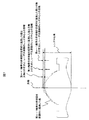
次に、図5を用いて、光ピックアップレンズ14のレンズ面形状を説明する。図5は、ピックアップレンズの一例である対物レンズを示す側面図である。光ピックアップレンズ14のレーザ光源側のレンズ面(R1面)及び光ディスク側のレンズ面(R2面)の面形状の定義について説明する。なお、本実施形態において、光ピックアップレンズ14を定義する場合、光軸に対して平行な方向であって、レーザ光源側のレンズ面(R1面)から光ディスク側のレンズ面(R2面)に向かう方向を正の方向とする。
Next, the lens surface shape of the
次に、本実施例おける光ピックアップレンズ14のディスク側面(R2面)の面形状について説明する。図5において、対物レンズの光入射面R2の頂点をe、頂点eと接する接面上における光線高さhの点をc、この点cから光軸OAに平行な方向での光入射面R1上の点をdとすると、任意の光線高さh(mm)に対する点c,d間の距離ZB(mm)が

なお、本実施例にかかるピックアップレンズ14のディスク側面(R2面)の第1輪帯領域、第2輪帯領域の面形状を規定する場合、(20)式の光線高さhには、それぞれ、表5に示す第1輪帯領域の輪帯領域位置の値を代入する。また、(20)式の係数Bは、それぞれ、表5に示す第1輪帯領域、第2輪帯領域の軸上段差量(mm)の値を代入する。そして、(20)式と表5に示す係数の値とにより、ピックアップレンズ14のディスク側面(R2面)の第1輪帯領域、第2輪帯領域の面形状が規定される。
When defining the surface shapes of the first and second annular zones on the disk side surface (R2 surface) of the
なお、(20)式に、上記係数C,K,A4,A6,A8,A10,A12,A14,A16の値を代入して任意の光線高さh(mm)(≠0)に対する距離ZB(mm)を求め、その値が負の値となった場合は、点dが、光ディスク側面(R2面)の光軸OAが通る面頂点eよりもレーザ側(図5での左側)に位置することを示している。距離ZB(mm)が正の値である場合には、点dが頂点eよりもディスク側(図5での右側)に位置することを示している。 It should be noted that the value of the coefficients C, K, A 4 , A 6 , A 8 , A 10 , A 12 , A 14 , A 16 is substituted into the equation (20) to obtain an arbitrary light height h (mm) ( When the distance Z B (mm) for ≠ 0) is obtained and the value becomes a negative value, the point d is closer to the laser side than the surface vertex e through which the optical axis OA of the optical disk side surface (R2 surface) passes (see FIG. 5 (left side in FIG. 5). When the distance Z B (mm) is a positive value, it indicates that the point d is located on the disc side (right side in FIG. 5) from the vertex e.
次に、光ピックアップレンズ14のレーザ側面(R1面)の面形状について説明する。図5において、対物レンズの光入射面R1の頂点をf、頂点fと接する接面上における光線高さhの点をa、この点aから光軸OAに平行な方向での光入射面R1上の点をbとすると、任意の光線高さh(mm)に対する点a,b間の距離ZA(mm)が
なお、本実施例にかかるピックアップレンズ14の第1輪帯領域、第2輪帯領域、・・・、第N輪帯領域(Nは正の整数)の面形状を規定する場合、(21)式の光線高さhには、それぞれ、表5に示す第1輪帯領域、第2輪帯領域、・・・、第N輪帯領域の輪帯領域位置の値を代入する。また、実施例1にかかるピックアップレンズ14の第1輪帯領域、第2輪帯領域、・・・、第N輪帯領域の面形状を規定する場合、(21)式と表5に示す係数の値とにより、実施例1にかかるピックアップレンズ14の第1輪帯領域〜第N輪帯領域の面形状が規定される。
In the case where the surface shapes of the first annular region, the second annular region,..., The Nth annular region (N is a positive integer) of the
ここで、(21)式において、軸上段差量Dnに対応する係数Bの値に関して、例えば第n輪帯領域(2≦n≦N)の係数Bを変更しても、残りの係数C,K,A4,A6,A8,A10,A12,A14,A16も変更することにより、ZA(mm)をほとんど同様の値をとることも可能となることがわかる。 Here, in the equation (21), regarding the value of the coefficient B corresponding to the axial step amount D n , for example, even if the coefficient B of the n-th annular zone region (2 ≦ n ≦ N) is changed, the remaining coefficient C , K, A 4 , A 6 , A 8 , A 10 , A 12 , A 14 , A 16 , it is understood that Z A (mm) can be almost the same value.
また、第m輪帯(mは1<m<Nを満たす整数)以降に形成されている接合領域についても、(21)式を用いることにより表現できる。本実施例における接合領域である第n−(n+1)輪帯間(nは、m≦n≦Nを満たす整数)における(21)式と表5に示す係数の値とにより、実施例1にかかるピックアップレンズ14の接合領域の面形状も規定される。
Also, the junction region formed after the m-th annular zone (m is an integer satisfying 1 <m <N) can be expressed by using the equation (21). According to the formula (21) and the coefficient values shown in Table 5 between the n- (n + 1) th annular zones (n is an integer satisfying m ≦ n ≦ N), which is the junction region in the present embodiment, The surface shape of the joining region of the
次に、ピックアップレンズ14の隣接段差量について定義する。図6に、ピックアップレンズ14を模式的に表す側面図を示す。隣接段差量とは、図6に示すように、各輪帯領域間における段差量のことである。尚、隣接段差量dの符号については、いわゆる幾何光学と同様の符号をとるものとし、レンズ中心側における輪帯の最外側地点から、次の輪帯の最内側地点がディスク側(図6での右側)となるときに+(プラス)、レーザ側(図6での左側)になるときに−(マイナス)の符号をとるものとする。
Next, the adjacent step amount of the
なお、光ピックアップレンズ14のレーザ光源側のレンズ面(R1面)又は光ディスク側のレンズ面(R2面)は上述の面形状に限られるものではない。例えば、レーザ光源側の(R1面)又は光ディスク側のレンズ面(R2面)に構造体が形成されていてもよい。また、光ピックアップレンズ14のレーザ光源側のレンズ面(R1面)の面形状も上述の面形状に限られない。例えば、レーザ光源側のレンズ(R1面)又は光ディスク側のレンズ面(R2面)に、ある一定の幅と深さをもった輪帯が同心円状にまたはスパイラル状に形成されていてもよい。
The lens surface (R1 surface) on the laser light source side or the lens surface (R2 surface) on the optical disk side of the
また、光ピックアップレンズ14のレーザ光源側のレンズ面(R1面)又は光ディスク側のレンズ面(R2面)に、反射防止膜や反射膜のような入射光の透過率を制御する膜が成膜されていてもよい。これらの膜の膜厚や材料は、所望する光ピックアップレンズ14の透過率性能を達成できるように選定される。また、これらの膜は、1層の薄膜からなる単層の構成でもよいし、複数の薄膜が積層された複数層の構成であってもよい。これらの膜を複数層の薄膜から構成する場合は、異なる材料の薄膜を交互に積層させてもよい。
Further, a film for controlling the transmittance of incident light, such as an antireflection film or a reflection film, is formed on the lens surface (R1 surface) on the laser light source side of the
薄膜の材料としては、AlF3、AlN、Al2O3、BaF2、BeO、Bi2O3、BiF3、CaF2、CdSe、CdS、CdTe、CeF3、CeO2、CsI、Cr2O3、DyF2、Fe2O3、GaAs、GdF3、Gd2O3、Ge、HfO2、HoF3、In2O3、ITO、LaF3、La2O3、LiF、MgF2、MgO、NaF、Na3AlF6、Na5Al3F14、Nb2O5、NdF3、Nd2O3、PbCl2、PbF2、PbTe、PbO、PbS、Pr6O11、Sb2S3、Sb2O3、Sc2O3Si、Si3N4、SiO、Si2O3、SiO2、SnO2、SrO2、SrF2、Ta2O5、Te、Ti、TiN、TiNxWv、TiO2、TlCl、ThF4、ThO2、V2O5、WO3、YF3、Y2O3、YbF3、Yb2O3、ZnO、ZnS、ZnSe、ZrO2等が挙げられる。
As the material of the thin film, AlF 3 , AlN, Al 2 O 3 , BaF 2 , BeO, Bi 2 O 3 , BiF 3 , CaF 2 , CdSe, CdS, CdTe, CeF 3 , CeO 2 , CsI, Cr 2 O 3 , DyF 2, Fe 2 O 3 , GaAs,
以下に、本発明にかかる実施例1乃至30を説明する。なお、本発明の範囲は、実施例により限定されるものではない。 Examples 1 to 30 according to the present invention will be described below. The scope of the present invention is not limited by the examples.
図8〜15は、本発明の実施例1〜30の波面収差図である。ここで、各図には、左右2つの図があるが、光軸に垂直な2つの方向を示すものであり、横軸は各実施例の有効半径を1としたときの相対瞳座標、縦軸は波面収差(λ)である。また、表示範囲は、横軸は±1、縦軸は±50λである。 8 to 15 are wavefront aberration diagrams of Examples 1 to 30 of the invention. Here, each figure has two figures on the left and right, but shows two directions perpendicular to the optical axis, and the horizontal axis shows the relative pupil coordinates when the effective radius of each embodiment is 1, and the vertical axis. The axis is wavefront aberration (λ). The display range is ± 1 on the horizontal axis and ± 50λ on the vertical axis.
表1から3に、実施例1乃至30に用いた光ピックアップレンズ14及びディスク15の屈折率一覧を示す。尚、波面収差特性における各記号の意味は、以下の通りである。
TOTAL:TOTAL波面収差
SA3:3次球面収差
COMA3:3次コマ収差
AS3:3次非点収差
TOTAL: TOTAL wavefront aberration SA3: third-order spherical aberration COMA3: third-order coma aberration AS3: third-order astigmatism
表4に、実施例1乃至30における構成を示す。
(表5)に、実施例1乃至30における光ピックアップレンズ14のレンズデータを示す。
(表6)に、実施例1乃至30における隣接段差量(但し、谷輪帯より内側の輪帯間のみ)を示す。
(表7)に、実施例1乃至30における各請求項と対応する比較表を示す。
(表8)に、実施例1乃至30における光学特性の比較表を示す。
(表9)に、実施例2の第6輪帯のサグ(ZA)と実施例30の第6輪帯のサグの比較表を示す。
ここで、実施例30についてのみ詳細に説明する。実施例30は、実施例2からR1面の第6輪帯の軸上段差量B(=D6)及び非球面係数のみ変更し、両実施例は、ほぼ同一の形状としたものである。 Here, only Example 30 will be described in detail. In Example 30, only the on-axis step amount B (= D 6 ) and the aspherical coefficient of the sixth annular zone on the R1 surface are changed from Example 2, and both examples have substantially the same shape.
具体的には、(表5)に示す実施例2のB(=D6)を0.005410305mmから0.008mmに変更して設計した。実施例2の第6輪帯のサグ(ZA)と実施例30の第6輪帯のサグを比較したものが(表10)である。 Specifically, B (= D 6 ) of Example 2 shown in (Table 5) was changed from 0.005410305 mm to 0.008 mm. A comparison of the sixth annular zone sag (Z A ) of Example 2 and the sixth annular zone sag of Example 30 is (Table 10).
(表9)から明らかなように、軸上段差量D6は2.6μmも異なるのに、サグ量については、最大でもh=1.169415mmにおいて5pmしか変わっていない。また、光学特性についても表8において比較すると明らかなように、実施例2と30は同等となっている。よって、輪帯構造のレンズにおいて、ある輪帯における軸上段差量B(=Dn)を全く別な値にしても、本発明と同じ効果を得ることは可能である。 As apparent from (Table 9), the on-axis step amount D 6 differs by 2.6 μm, but the sag amount changes only 5 pm at the maximum at h = 1.169415 mm. In addition, as is clear from the comparison in Table 8 with respect to the optical characteristics, Examples 2 and 30 are equivalent. Therefore, in a lens having an annular zone, even if the on-axis step difference B (= D n ) in a certain annular zone is set to a completely different value, the same effect as that of the present invention can be obtained.
11 光源(レーザ光源)
12 ビームスプリッタ
13 コリメータレンズ
14 ピックアップレンズ(光ピックアップ対物レンズ)
14−1 ピックアップレンズ
14−2 ピックアップレンズ
15 光ディスク
16 検出系
101 レンズ面
102 レンズ面
103 第m輪帯
104 接合領域
201 レンズ面
202 レンズ面
203 第m輪帯
204 接合領域
11 Light source (laser light source)
12
14-1 Pickup Lens 14-2
Claims (20)
NA≧0.8 ・・・・・・(1)
1.0≦f≦1.8 ・・・・(2) A plastic optical pickup objective lens for condensing a light beam emitted from a laser light source onto an optical disk such as a BD (Blu-ray Disc), wherein the optical pickup objective lens includes a lens surface (R1 surface) on the laser light source side and an optical disk. A plurality of annular zones on both surfaces of the side lens surface (R2 surface), and the lens surface is divided into a plurality of concentric annular zones by a step, and a joining region is provided between the annular zones. The plurality of steps have a step amount that generates a phase difference in the incident light flux that reduces the aberration generated in the optical pickup objective lens when the ambient temperature changes, An optical pickup objective lens that satisfies the formulas (1) and (2) when the numerical aperture of the optical pickup objective lens is NA and the focal length is f (mm).
NA ≧ 0.8 (1)
1.0 ≦ f ≦ 1.8 (2)
NA≧0.84 ・・・・・・(1)´ The optical pickup objective lens according to claim 1, wherein the numerical expression (1) ′ is satisfied, where NA is a numerical aperture of the optical pickup objective lens.
NA ≧ 0.84 ・ ・ ・ ・ ・ ・ (1) ′
RN(R1)×d0m(R1)≧RN(R2)×d0m(R2) ・・・(3) The number of ring zones of the lens surface (R1 surface) on the laser light source side is RN (R1), the number of ring zones of the lens surface (R2 surface) on the optical disk side is RN (R2), and the absolute value of the step amount on the R1 surface axis is 2. The optical pickup objective lens according to claim 1, wherein the average value is d 0m (R1) (mm), and the average value of the absolute value of the step amount on the R2 plane axis is d 0m (R2). .
RN (R1) × d 0m (R1) ≧ RN (R2) × d 0m (R2) (3)
|Dm−1|<|Dm| ・・・・・(4)
|Dm|>|Dm+1| ・・・・・(5)
前記第m輪帯の前記レンズにおいて、中心側の境界の半径をRb、外縁側の境界の半径をRe、輪帯幅をRw(=Re−Rs)、開口数NAが0.85であるときの前記光ピックアップレンズの有効半径をRsとした場合、以下の(6)式を満たす事を特徴とする請求項1記載の光ピックアップレンズ。
Rw/Rs×100≧25(%) ・・・・・(6) The ring zone structure on the surface having the larger number of ring zones has the zone zones extending from the center of the lens toward the outer edge of the lens as the first zone, the second zone, ..., the Nth zone. (N is a positive integer), and when the aspheric surface of the n-th annular zone (n is an integer satisfying 1 ≦ n ≦ N) is virtually extended toward the lens center, the aspheric surface and the lens An intersection point with the optical axis passing through the center is C n (n is an integer satisfying 1 ≦ n ≦ N), and a distance between the intersection point C 1 and the intersection point C n is an axial step amount D n, which is parallel to the optical axis. When the direction toward the optical disk side is a positive direction, at least one m-th zone (m is an integer satisfying 1 <m <N) satisfying the following expressions (4) and (5) is provided:
| D m-1 | <| D m | (4)
| D m |> | D m + 1 | (5)
In the lens of the m-th annular zone, when the radius of the boundary on the center side is Rb, the radius of the boundary on the outer edge side is Re, the zone width is Rw (= Re−Rs), and the numerical aperture NA is 0.85 The optical pickup lens according to claim 1, wherein when the effective radius of the optical pickup lens is Rs, the following expression (6) is satisfied.
Rw / Rs × 100 ≧ 25 (%) (6)
|Em−1|<|Em| ・・・・・(7)
|Em|>|Em+1| ・・・・・(8)
前記第m輪帯の前記レンズにおいて、中心側の境界の半径をRb、外縁側の境界の半径をRe、輪帯幅をRw(=Re−Rs)、開口数NAが0.85であるときの前記光ピックアップレンズの有効半径をRsとした場合、以下の(6)式を満たす事を特徴とする請求項1記載の光ピックアップレンズ。
Rw/Rs×100≧25(%) ・・・・・(6) The ring zone structure on the surface having the larger number of ring zones has the zone zones extending from the center of the lens toward the outer edge of the lens as the first zone, the second zone, ..., the Nth zone. (N is a positive integer), and when the optical path difference between a light beam passing through the n-th annular zone (n is an integer satisfying 1 ≦ n ≦ N) and a light beam passing on the optical axis is E n (λ), Including at least one m-th zone (m is an integer satisfying 1 <m <N) satisfying the equations (7) and (8).
| E m-1 | <| E m | (7)
| E m | >> | E m + 1 | (8)
In the lens of the m-th annular zone, when the radius of the boundary on the center side is Rb, the radius of the boundary on the outer edge side is Re, the zone width is Rw (= Re−Rs), and the numerical aperture NA is 0.85 The optical pickup lens according to claim 1, wherein when the effective radius of the optical pickup lens is Rs, the following expression (6) is satisfied.
Rw / Rs × 100 ≧ 25 (%) (6)
前記接合領域の面形状は、前記接合領域の面上の実質的に全ての点の前記光軸方向における位置が前記第n−1輪帯の前記レンズ外縁側の境界の前記光軸方向における位置よりも前記光ディスク側となる形状となる請求項1に記載の光ピックアップ対物レンズ。 The ring zone structure on the surface having the larger number of ring zones has the zone zones extending from the center of the lens toward the outer edge of the lens as the first zone, the second zone, ..., the Nth zone. (N is a positive integer), and when the aspheric surface of the n-th annular zone (n is an integer satisfying 1 ≦ n ≦ N) is virtually extended toward the lens center, the aspheric surface and the lens An intersection point with the optical axis passing through the center is C n (n is an integer satisfying 1 ≦ n ≦ N), and a distance between the intersection point C 1 and the intersection point C n is an axial step amount D n, which is parallel to the optical axis. When the direction toward the optical disk side is a positive direction, it includes a junction region provided between at least one n-1 annular zone and the nth annular zone satisfying D n-1 > D n
The surface shape of the bonding region is such that the positions of substantially all points on the surface of the bonding region in the optical axis direction are the positions in the optical axis direction of the boundary on the lens outer edge side of the n-1 zone. The optical pickup objective lens according to claim 1, wherein the objective lens has a shape that is closer to the optical disc side.
前記接合領域の面形状は、前記接合領域の面上の実質的に全ての点の前記光軸方向における位置が前記第n−1輪帯の前記レンズ外縁側の境界の前記光軸方向における位置よりも前記光ディスク側となる形状となる請求項1に記載の光ピックアップ対物レンズ。 The ring zone structure on the surface having the larger number of ring zones has the zone zones extending from the center of the lens toward the outer edge of the lens as the first zone, the second zone, ..., the Nth zone. (N is a positive integer), and when the aspheric surface of the n-th annular zone (n is an integer satisfying 1 ≦ n ≦ N) is virtually extended toward the lens center, the aspheric surface and the lens An intersection point with the optical axis passing through the center is C n (n is an integer satisfying 1 ≦ n ≦ N), and a distance between the intersection point C 1 and the intersection point C n is an axial step amount D n, which is parallel to the optical axis. When the direction toward the optical disk side is a positive direction, the apparatus includes a junction region provided between all the n-1 annular zones and the nth annular zone that satisfy D n-1 > D n .
The surface shape of the bonding region is such that the positions of substantially all points on the surface of the bonding region in the optical axis direction are the positions in the optical axis direction of the boundary on the lens outer edge side of the n-1 zone. The optical pickup objective lens according to claim 1, wherein the objective lens has a shape that is closer to the optical disc side.
前記接合領域の面形状は、前記接合領域の面上の実質的に全ての点の前記光軸方向における位置が前記第n−1輪帯の前記レンズ外縁側の境界の前記光軸方向における位置よりも前記光ディスク側となる形状となる請求項1に記載の光ピックアップ対物レンズ。 The ring zone structure on the surface having the larger number of ring zones has the zone zones extending from the center of the lens toward the outer edge of the lens as the first zone, the second zone, ..., the Nth zone. (N is a positive integer), and when the aspheric surface of the n-th annular zone (n is an integer satisfying 1 ≦ n ≦ N) is virtually extended toward the lens center, the aspheric surface and the lens An intersection point with the optical axis passing through the center is C n (n is an integer satisfying 1 ≦ n ≦ N), and a distance between the intersection point C 1 and the intersection point C n is an axial step amount D n, which is parallel to the optical axis. When the direction toward the optical disk side is a positive direction, the position in the lens radial direction of the boundary on the lens center side of the nth annular zone that satisfies D n−1 > D n is the lens surface of the optical pickup lens. When the tangent angle is within a range of 40 ° or more, a junction region provided between the n-1 ring zone and the nth ring zone is Prepared,
The surface shape of the bonding region is such that the positions of substantially all points on the surface of the bonding region in the optical axis direction are the positions in the optical axis direction of the boundary on the lens outer edge side of the n-1 zone. The optical pickup objective lens according to claim 1, wherein the objective lens has a shape that is closer to the optical disc side.
0≦θ≦15 ・・・・・(9) The optical pickup lens according to claim 9, wherein the following expression (9) is satisfied.
0 ≦ θ ≦ 15 (9)
3≦(N−1)×|dn|/λ≦15 ・・・・・・(10) The absolute value of the adjacent step amount between the n-th annular zone (2 ≦ n ≦ m) and the n−1-th annular zone is | dn | (mm), the design wavelength is λ (mm), the design wavelength and the design temperature. The optical pickup objective lens according to any one of claims 1 to 12, which satisfies Formula (10), where N is a refractive index of the optical pickup objective lens.
3 ≦ (N−1) × | dn | / λ ≦ 15 (10)
3≦(N−1)×|dn0|/λ≦12 ・・・・・・(11) Wherein the n zones (2 ≦ n ≦ N) of the on-axis step difference D n of the absolute value of the difference between on-axis step difference D n-1 of the (n-1) th annular | dn 0 | (mm) The formula (11) is satisfied when the design wavelength is λ (mm) and the refractive index of the optical pickup objective lens at the design wavelength and the design temperature is N. Optical pickup objective lens.
3 ≦ (N−1) × | dn 0 | / λ ≦ 12 (11)
10≦(N−1)×(Σ|d|max−Σ|d|min)/λ≦40 ・・(12) The maximum value of the cumulative value Σ | d | of the absolute value of the adjacent step amount of the n-th annular zone (2 ≦ n ≦ m) and the n−1-th annular zone is Σ | d | max, and the cumulative value Σ | d The optical pickup objective lens according to claim 1, wherein the minimum value of | is Σ | d | min, and the mathematical expression (12) is satisfied.
10 ≦ (N−1) × (Σ | d | max−Σ | d | min) / λ ≦ 40 (12)
18≦(N−1)×(Dmax−Dmin)/λ≦40 ・・・・(13) 15. The system according to claim 1, wherein the maximum value of the on-axis step amount D n of the n-th annular zone (1 ≦ n ≦ N) is Dmax and the minimum value is Dmin, and satisfies Formula (13). The optical pickup objective lens described in 1.
18 ≦ (N−1) × (Dmax−Dmin) / λ ≦ 40 (13)
α−β≧ 0 ・・・・・(14) For all n-1 zones and n-th zone that satisfy D n-1 <D n , an axial step amount D n of the n- th zone and an axial step amount D of the n-1 zone. The value obtained by adding the absolute value | dn 0 | of the difference from n−1 is α, and for all the n−1 and nth annular zones that satisfy D n−1 > D n , In the case where β is a value obtained by adding the absolute value | dn 0 | of the difference between the on-axis step amount D n of the n-zone and the on-axis step amount D n-1 of the ( n−1) -th zone. The optical pickup lens according to claim 1, wherein the following expression (14) is satisfied.
α−β ≧ 0 (14)
0.8≦α/β≦1.2 ・・・・・(15) For all n-1 zones and n-th zone that satisfy D n-1 <D n , the on-axis step amount Dn of the n-th zone and the on-axis step amount D n of the n-1 zone. The value obtained by adding the absolute value | dn 0 | of the difference from −1 is α, and for all the n−1 and nth annular zones that satisfy D n−1 > D n , the n th When the value obtained by adding the absolute value | dn 0 | of the difference between the on-axis step amount Dn of the annular zone and the on-axis step amount D n-1 of the ( n−1) -th zone is β, The optical pickup lens according to any one of claims 1 to 16, which satisfies the expression (15).
0.8 ≦ α / β ≦ 1.2 (15)
Priority Applications (2)
| Application Number | Priority Date | Filing Date | Title |
|---|---|---|---|
| JP2010106448A JP2011238304A (en) | 2010-05-06 | 2010-05-06 | Optical pickup lens |
| PCT/JP2011/060282 WO2011138919A1 (en) | 2010-05-06 | 2011-04-27 | Optical pickup lens |
Applications Claiming Priority (1)
| Application Number | Priority Date | Filing Date | Title |
|---|---|---|---|
| JP2010106448A JP2011238304A (en) | 2010-05-06 | 2010-05-06 | Optical pickup lens |
Publications (2)
| Publication Number | Publication Date |
|---|---|
| JP2011238304A true JP2011238304A (en) | 2011-11-24 |
| JP2011238304A5 JP2011238304A5 (en) | 2012-11-29 |
Family
ID=44903771
Family Applications (1)
| Application Number | Title | Priority Date | Filing Date |
|---|---|---|---|
| JP2010106448A Pending JP2011238304A (en) | 2010-05-06 | 2010-05-06 | Optical pickup lens |
Country Status (2)
| Country | Link |
|---|---|
| JP (1) | JP2011238304A (en) |
| WO (1) | WO2011138919A1 (en) |
Citations (4)
| Publication number | Priority date | Publication date | Assignee | Title |
|---|---|---|---|---|
| JP2004101954A (en) * | 2002-09-10 | 2004-04-02 | Konica Minolta Holdings Inc | Synthetic resin lens and optical pickup apparatus using same |
| JP2004310976A (en) * | 2003-03-26 | 2004-11-04 | Asahi Glass Co Ltd | Optical pickup |
| JP2009295244A (en) * | 2008-06-06 | 2009-12-17 | Ricoh Co Ltd | Optical element, optical pickup, and optical information processor |
| JP2010080040A (en) * | 2008-04-10 | 2010-04-08 | Hitachi Maxell Ltd | Optical pickup objective lens, optical pickup device and optical disc apparatus |
Family Cites Families (2)
| Publication number | Priority date | Publication date | Assignee | Title |
|---|---|---|---|---|
| JP2005050433A (en) * | 2003-07-29 | 2005-02-24 | Asahi Glass Co Ltd | Objective lens and optical head device |
| JP2006024344A (en) * | 2004-06-11 | 2006-01-26 | Nidec Nissin Corp | Annular phase correction lens and optical head system |
-
2010
- 2010-05-06 JP JP2010106448A patent/JP2011238304A/en active Pending
-
2011
- 2011-04-27 WO PCT/JP2011/060282 patent/WO2011138919A1/en active Application Filing
Patent Citations (4)
| Publication number | Priority date | Publication date | Assignee | Title |
|---|---|---|---|---|
| JP2004101954A (en) * | 2002-09-10 | 2004-04-02 | Konica Minolta Holdings Inc | Synthetic resin lens and optical pickup apparatus using same |
| JP2004310976A (en) * | 2003-03-26 | 2004-11-04 | Asahi Glass Co Ltd | Optical pickup |
| JP2010080040A (en) * | 2008-04-10 | 2010-04-08 | Hitachi Maxell Ltd | Optical pickup objective lens, optical pickup device and optical disc apparatus |
| JP2009295244A (en) * | 2008-06-06 | 2009-12-17 | Ricoh Co Ltd | Optical element, optical pickup, and optical information processor |
Also Published As
| Publication number | Publication date |
|---|---|
| WO2011138919A1 (en) | 2011-11-10 |
Similar Documents
| Publication | Publication Date | Title |
|---|---|---|
| US6118594A (en) | Objective lens for optical pick-up | |
| TWI393132B (en) | Optical element, aberration correcting element, light converging element, objective optical system, optical pickup device, and optical information recording reproducing device | |
| US7123424B2 (en) | Objective lens for optical information recording medium | |
| US7755998B2 (en) | Optical pickup system, optical head, optical disk apparatus, and objective lens | |
| JP4060007B2 (en) | Optical system of optical disk device | |
| TW200400408A (en) | Recording reproducing optical system, objective lens, and aberration correcting optical element | |
| KR20020096938A (en) | Objective lens, optical pickup apparatus, and recording and/or reproducing apparatus | |
| US7924685B2 (en) | Objective lens | |
| JP4531649B2 (en) | Antireflection film, optical component for optical pickup, objective lens, and method for manufacturing optical component for optical pickup | |
| KR100506565B1 (en) | Objective lens for an optical disk | |
| US6781764B1 (en) | Objective lens for optical pick-up | |
| JP4296868B2 (en) | OPTICAL SYSTEM FOR OPTICAL PICKUP DEVICE, OPTICAL PICKUP DEVICE, AND OPTICAL INFORMATION RECORDING / REPRODUCING DEVICE | |
| JP4852271B2 (en) | Optical pickup optical system, optical head, and optical disc apparatus | |
| WO2011138919A1 (en) | Optical pickup lens | |
| JP4232188B2 (en) | Objective lens for optical pickup device, optical pickup device and optical information recording / reproducing device | |
| WO2011013339A1 (en) | Light pickup lens | |
| JP2005535063A (en) | Scanning device including an objective lens formed of two kinds of materials | |
| JP4070941B2 (en) | Objective lens for optical head | |
| JP2012053958A (en) | Objective lens for optical pickup and optical pickup device | |
| JP5119080B2 (en) | Optical element for pickup for optical recording reading | |
| JP2006114081A (en) | Objective lens and optical pickup system | |
| JP5180138B2 (en) | Optical pickup lens | |
| JP2011028830A (en) | Objective lens for optical pickup | |
| JP2010281847A (en) | Objective lens | |
| JP2005050433A (en) | Objective lens and optical head device |
Legal Events
| Date | Code | Title | Description |
|---|---|---|---|
| A711 | Notification of change in applicant |
Free format text: JAPANESE INTERMEDIATE CODE: A712 Effective date: 20120703 |
|
| A521 | Written amendment |
Free format text: JAPANESE INTERMEDIATE CODE: A523 Effective date: 20121017 |
|
| A621 | Written request for application examination |
Free format text: JAPANESE INTERMEDIATE CODE: A621 Effective date: 20121017 |
|
| A131 | Notification of reasons for refusal |
Free format text: JAPANESE INTERMEDIATE CODE: A131 Effective date: 20131203 |
|
| A02 | Decision of refusal |
Free format text: JAPANESE INTERMEDIATE CODE: A02 Effective date: 20140422 |