JP2011237480A - Image forming device - Google Patents
Image forming device Download PDFInfo
- Publication number
- JP2011237480A JP2011237480A JP2010106404A JP2010106404A JP2011237480A JP 2011237480 A JP2011237480 A JP 2011237480A JP 2010106404 A JP2010106404 A JP 2010106404A JP 2010106404 A JP2010106404 A JP 2010106404A JP 2011237480 A JP2011237480 A JP 2011237480A
- Authority
- JP
- Japan
- Prior art keywords
- relay
- heater
- temperature
- control signal
- image forming
- Prior art date
- Legal status (The legal status is an assumption and is not a legal conclusion. Google has not performed a legal analysis and makes no representation as to the accuracy of the status listed.)
- Granted
Links
Images
Classifications
-
- G—PHYSICS
- G03—PHOTOGRAPHY; CINEMATOGRAPHY; ANALOGOUS TECHNIQUES USING WAVES OTHER THAN OPTICAL WAVES; ELECTROGRAPHY; HOLOGRAPHY
- G03G—ELECTROGRAPHY; ELECTROPHOTOGRAPHY; MAGNETOGRAPHY
- G03G15/00—Apparatus for electrographic processes using a charge pattern
- G03G15/20—Apparatus for electrographic processes using a charge pattern for fixing, e.g. by using heat
- G03G15/2003—Apparatus for electrographic processes using a charge pattern for fixing, e.g. by using heat using heat
- G03G15/2014—Apparatus for electrographic processes using a charge pattern for fixing, e.g. by using heat using heat using contact heat
- G03G15/2039—Apparatus for electrographic processes using a charge pattern for fixing, e.g. by using heat using heat using contact heat with means for controlling the fixing temperature
- G03G15/205—Apparatus for electrographic processes using a charge pattern for fixing, e.g. by using heat using heat using contact heat with means for controlling the fixing temperature specially for the mode of operation, e.g. standby, warming-up, error
-
- G—PHYSICS
- G03—PHOTOGRAPHY; CINEMATOGRAPHY; ANALOGOUS TECHNIQUES USING WAVES OTHER THAN OPTICAL WAVES; ELECTROGRAPHY; HOLOGRAPHY
- G03G—ELECTROGRAPHY; ELECTROPHOTOGRAPHY; MAGNETOGRAPHY
- G03G15/00—Apparatus for electrographic processes using a charge pattern
- G03G15/20—Apparatus for electrographic processes using a charge pattern for fixing, e.g. by using heat
- G03G15/2003—Apparatus for electrographic processes using a charge pattern for fixing, e.g. by using heat using heat
- G03G15/2014—Apparatus for electrographic processes using a charge pattern for fixing, e.g. by using heat using heat using contact heat
- G03G15/2039—Apparatus for electrographic processes using a charge pattern for fixing, e.g. by using heat using heat using contact heat with means for controlling the fixing temperature
-
- G—PHYSICS
- G03—PHOTOGRAPHY; CINEMATOGRAPHY; ANALOGOUS TECHNIQUES USING WAVES OTHER THAN OPTICAL WAVES; ELECTROGRAPHY; HOLOGRAPHY
- G03G—ELECTROGRAPHY; ELECTROPHOTOGRAPHY; MAGNETOGRAPHY
- G03G15/00—Apparatus for electrographic processes using a charge pattern
- G03G15/55—Self-diagnostics; Malfunction or lifetime display
-
- G—PHYSICS
- G03—PHOTOGRAPHY; CINEMATOGRAPHY; ANALOGOUS TECHNIQUES USING WAVES OTHER THAN OPTICAL WAVES; ELECTROGRAPHY; HOLOGRAPHY
- G03G—ELECTROGRAPHY; ELECTROPHOTOGRAPHY; MAGNETOGRAPHY
- G03G15/00—Apparatus for electrographic processes using a charge pattern
- G03G15/80—Details relating to power supplies, circuits boards, electrical connections
-
- G—PHYSICS
- G03—PHOTOGRAPHY; CINEMATOGRAPHY; ANALOGOUS TECHNIQUES USING WAVES OTHER THAN OPTICAL WAVES; ELECTROGRAPHY; HOLOGRAPHY
- G03G—ELECTROGRAPHY; ELECTROPHOTOGRAPHY; MAGNETOGRAPHY
- G03G21/00—Arrangements not provided for by groups G03G13/00 - G03G19/00, e.g. cleaning, elimination of residual charge
- G03G21/16—Mechanical means for facilitating the maintenance of the apparatus, e.g. modular arrangements
- G03G21/1661—Mechanical means for facilitating the maintenance of the apparatus, e.g. modular arrangements means for handling parts of the apparatus in the apparatus
- G03G21/1685—Mechanical means for facilitating the maintenance of the apparatus, e.g. modular arrangements means for handling parts of the apparatus in the apparatus for the fixing unit
-
- G—PHYSICS
- G03—PHOTOGRAPHY; CINEMATOGRAPHY; ANALOGOUS TECHNIQUES USING WAVES OTHER THAN OPTICAL WAVES; ELECTROGRAPHY; HOLOGRAPHY
- G03G—ELECTROGRAPHY; ELECTROPHOTOGRAPHY; MAGNETOGRAPHY
- G03G2215/00—Apparatus for electrophotographic processes
- G03G2215/20—Details of the fixing device or porcess
- G03G2215/2003—Structural features of the fixing device
- G03G2215/2016—Heating belt
- G03G2215/2025—Heating belt the fixing nip having a rotating belt support member opposing a pressure member
- G03G2215/2032—Heating belt the fixing nip having a rotating belt support member opposing a pressure member the belt further entrained around additional rotating belt support members
-
- G—PHYSICS
- G03—PHOTOGRAPHY; CINEMATOGRAPHY; ANALOGOUS TECHNIQUES USING WAVES OTHER THAN OPTICAL WAVES; ELECTROGRAPHY; HOLOGRAPHY
- G03G—ELECTROGRAPHY; ELECTROPHOTOGRAPHY; MAGNETOGRAPHY
- G03G2221/00—Processes not provided for by group G03G2215/00, e.g. cleaning or residual charge elimination
- G03G2221/16—Mechanical means for facilitating the maintenance of the apparatus, e.g. modular arrangements and complete machine concepts
- G03G2221/1639—Mechanical means for facilitating the maintenance of the apparatus, e.g. modular arrangements and complete machine concepts for the fixing unit
Landscapes
- Physics & Mathematics (AREA)
- General Physics & Mathematics (AREA)
- Fixing For Electrophotography (AREA)
- Control Of Resistance Heating (AREA)
- Control Or Security For Electrophotography (AREA)
Abstract
【課題】本発明は、定着ヒータの両端にそれぞれリレーが接続された回路構成において、各リレーで発生した接点融着を個別に検出できる画像形成装置を提供する。
【解決手段】制御部110は、定着ヒータ601への通電を開始する前に第1のリレー501をONするように制御信号を出力し、ゼロクロス検知回路505により入力電圧が検知されていない場合、第2のリレー502をONするように制御信号を出力する。第1のリレー501がONされたときにゼロクロス検知回路505により入力電圧が検知された場合は、第2のリレーが故障していると判断する。定着ヒータ601への通電を終了する前に第1のリレー501をOFFするように制御信号を出力し、ゼロクロス検知回路505により入力電圧が検知されていない場合、第2のリレー502をOFFするように制御信号を出力する。第1のリレー501がOFFされたときにゼロクロス検知回路505により入力電圧が検知された場合は、第1のリレー501が故障していると判断する。
【選択図】図3The present invention provides an image forming apparatus capable of individually detecting contact fusion generated in each relay in a circuit configuration in which relays are connected to both ends of a fixing heater.
A control unit outputs a control signal to turn on a first relay before starting energization to a fixing heater, and when an input voltage is not detected by a zero-cross detection circuit. A control signal is output to turn on the second relay 502. If the input voltage is detected by the zero cross detection circuit 505 when the first relay 501 is turned on, it is determined that the second relay is out of order. Before the energization of the fixing heater 601 is finished, a control signal is output so that the first relay 501 is turned off, and when the input voltage is not detected by the zero cross detection circuit 505, the second relay 502 is turned off. Output a control signal. If the input voltage is detected by the zero cross detection circuit 505 when the first relay 501 is turned off, it is determined that the first relay 501 is out of order.
[Selection] Figure 3
Description
本発明は、電子写真方式を利用して記録材に画像形成を行う複写機、プリンタ等の画像形成装置に関し、特に、記録材に形成担持された未定着トナーを加熱定着する定着装置への給電経路に関する。
BACKGROUND OF THE
従来、電子写真方式の画像形成装置では、一般的に、記録用紙に形成されたトナー像を加熱して定着させる方式(熱定着方式)が採用され、中でも加熱源を内包する回転体に直接トナー像を接触させて定着させる方式が広く用いられている。加熱源としては、ハロゲンヒータ、セラミックヒータ、IHヒーティングなどが知られているが、いずれも数百Wという大電力を必要とする。 Conventionally, an electrophotographic image forming apparatus generally employs a method (heat fixing method) in which a toner image formed on a recording sheet is heated and fixed, and in particular, a toner is directly applied to a rotating body containing a heating source. A method of fixing an image by contacting it is widely used. As a heating source, a halogen heater, a ceramic heater, IH heating, and the like are known, but all require a large power of several hundred W.
また、近年の省エネ化の流れに対して、画像形成装置の待機電力の低減が重要な課題となっている。そのため、セラミックヒータを用いたオンデマンド定着技術によって定着温度の立ち上がりを高速化することで、待機電力をほとんど必要としない画像形成装置が提案されている。 Further, with respect to the recent trend of energy saving, reduction of standby power of the image forming apparatus has become an important issue. For this reason, there has been proposed an image forming apparatus that requires almost no standby power by speeding up the rise of the fixing temperature by an on-demand fixing technique using a ceramic heater.
一方、こうした高速立ち上げの定着装置においては、加熱源である定着ヒータの温度上昇が急峻であるため、異常発生時は速やかに定着ヒータへの通電を遮断することが重要である。また、定着ヒータへの通電を確実に遮断するためには、定着ヒータの両端への電力供給を遮断する必要がある。 On the other hand, in such a fast start-up fixing device, since the temperature rise of the fixing heater as a heating source is steep, it is important to quickly cut off the energization to the fixing heater when an abnormality occurs. Further, in order to reliably cut off the energization to the fixing heater, it is necessary to cut off the power supply to both ends of the fixing heater.
定着ヒータに供給する電力を遮断するための手段として、メカリレーを使用することが一般的である。メカリレーは、接点を用いているため、ON/OFFを繰り返すと経年変化により接点が融着してしまう可能性がある。万が一、リレーの接点が融着してしまうと、OFFしたはずでも通電してしまうため、定着ヒータへの給電が停止せず、異常発熱するおそれがある。そこで、リレーの後段に入力電圧の有無を検知するゼロクロス検知回路を設け、リレーに対してOFFを指示しているにも関わらず、ゼロクロス信号が出力しているときにリレーの接点溶着が発生したと判断する手法が提案されている(例えば、特許文献1参照)。 A mechanical relay is generally used as a means for cutting off the power supplied to the fixing heater. Since the mechanical relay uses a contact, if the ON / OFF is repeated, the contact may be fused due to aging. In the unlikely event that the contact of the relay is fused, the power is supplied even if it is turned off, so that the power supply to the fixing heater does not stop and there is a risk of abnormal heat generation. Therefore, a zero cross detection circuit that detects the presence or absence of input voltage is provided at the subsequent stage of the relay, and relay contact welding occurs when the zero cross signal is output even though the relay is instructed to turn OFF. Has been proposed (see, for example, Patent Document 1).
上述の手法では、リレーの後段にゼロクロス検知回路を配置することでリレーの接点融着を検知可能にしている。 In the above-described method, the contact fusion of the relay can be detected by arranging a zero-cross detection circuit in the subsequent stage of the relay.
しかしながら、定着ヒータの両端にそれぞれリレーを配置した場合、両方のリレーが接点融着したときだけゼロクロス検知回路による検出が可能であり、どちらか一方のリレーの接点融着を検知することはできず、上述の手法が安全性の面で十分とは云えない。 However, when relays are arranged at both ends of the fixing heater, detection by the zero-cross detection circuit is possible only when both relays are fused, and it is not possible to detect contact fusion of either relay. The above method is not sufficient in terms of safety.
本発明は、上記問題に鑑みて成されたものであり、定着ヒータの両端にそれぞれリレーが接続された回路構成において、各リレーで発生した接点融着を個別に検出できる画像形成装置を提供することを目的とする。 The present invention has been made in view of the above problems, and provides an image forming apparatus capable of individually detecting contact fusion generated in each relay in a circuit configuration in which relays are connected to both ends of a fixing heater. For the purpose.
上記目的を達成するために、本発明に係る画像形成装置は、ヒータと、前記ヒータの両端にそれぞれ接続された第1のリレー及び第2のリレーと、前記第1のリレーから前記ヒータまで及び前記第2のリレーから前記ヒータまでの各経路上で前記ヒータへの入力電圧の有無を検知する電圧検知手段と、前記第1のリレー及び前記第2のリレーのそれぞれをON/OFFするための制御信号を出力するリレー制御手段とを備える画像形成装置において、前記リレー制御手段は、前記ヒータへの通電を開始する前に前記第1のリレーをONするように前記制御信号を出力し、前記電圧検知手段により入力電圧が検知されていない場合、前記第2のリレーをONするように前記制御信号を出力する第1の制御手段と、前記第1の制御手段により前記第1のリレーがONされたときに前記電圧検知手段により入力電圧が検知された場合は、前記第2のリレーが故障していると判断する第1の判断手段と、前記ヒータへの通電を終了する前に前記第1のリレーをOFFするように前記制御信号を出力し、前記電圧検知手段により入力電圧が検知されていない場合、前記第2のリレーをOFFするように前記制御信号を出力する第2の制御手段と、前記第2の制御手段により前記第1のリレーがOFFされたときに前記電圧検知手段により入力電圧が検知された場合は、前記第1のリレーが故障していると判断する第2の判断手段とを備えることを特徴とする。 In order to achieve the above object, an image forming apparatus according to the present invention includes a heater, a first relay and a second relay connected to both ends of the heater, the first relay to the heater, and the like. Voltage detection means for detecting the presence or absence of an input voltage to the heater on each path from the second relay to the heater, and for turning on / off each of the first relay and the second relay In the image forming apparatus including a relay control unit that outputs a control signal, the relay control unit outputs the control signal to turn on the first relay before starting energization of the heater, and When the input voltage is not detected by the voltage detection means, the first control means for outputting the control signal so as to turn on the second relay, and the first control means If the input voltage is detected by the voltage detection means when the first relay is turned on, the first determination means for determining that the second relay has failed and the energization of the heater is terminated. The control signal is output so that the first relay is turned off before the operation is performed, and when the input voltage is not detected by the voltage detection means, the control signal is output so that the second relay is turned off. If the input voltage is detected by the voltage detection means when the first control is turned off by the second control means and the second control means, the first relay is broken. And a second judging means for judging.
本発明によれば、定着ヒータの両端にそれぞれリレーが接続された回路構成において、各リレーで発生した接点融着を個別に検出することができる。また、接点融着検知を、一方はリレーON時、もう一方はリレーOFF時に実施することで二つのリレーの接点融着検知にかかる時間を低減させることができる。 According to the present invention, in the circuit configuration in which relays are connected to both ends of the fixing heater, contact fusion generated in each relay can be individually detected. Further, by performing contact fusion detection when one of the relays is ON and the other when the relay is OFF, the time required to detect contact fusion between the two relays can be reduced.
以下、本発明の実施の形態を図面を参照して詳細に説明する。 Hereinafter, embodiments of the present invention will be described in detail with reference to the drawings.
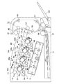
図1は、本発明の実施形態に係る画像形成装置の一例であるフルカラープリンタの概略構造を示す断面図である。 FIG. 1 is a cross-sectional view showing a schematic structure of a full-color printer which is an example of an image forming apparatus according to an embodiment of the present invention.
図1において、フルカラープリンタ(以下、単に「プリンタ」とする)は、4つの画像形成部を備える。即ち、イエロー色の画像を形成するための画像形成部1Yと、マゼンタ色の画像を形成するための画像形成部1Mと、シアン色の画像を形成するための画像形成部1Cと、ブラック色の画像を形成するための画像形成部1Bkである。これら4つの画像形成部1Y,1M,1C,1Bkは一定の間隔をおいて一列に配置される。
In FIG. 1, a full-color printer (hereinafter simply referred to as “printer”) includes four image forming units. That is, an
各画像形成部1Y〜1Bkには、それぞれ像担持体としてのドラム型の電子写真感光体(以下、「感光ドラム」という)2a,2b,2c,2dが設置されている。各感光ドラム2a〜2dの周囲には、一次帯電器3a,3b,3c,3d、現像装置4a,4b,4c,4d、転写手段としての転写ローラ5a,5b,5c,5d、ドラムクリーナ装置6a,6b,6c,6dがそれぞれ配置されている。一次帯電器3a〜3dと現像装置4a〜4dとの間の下方には、露光装置7が設置されている。
Each of the
各現像装置4a〜4dには、それぞれイエロートナー、シアントナー、マゼンタトナー、ブラックトナーが収納されている。
Each of the developing
各感光ドラム2a〜2dは、負帯電のOPC感光体でアルミニウム製のドラム基体上に光導電層を有しており、駆動装置(不図示)によって矢印方向(図1における時計回り方向)に所定のプロセススピードで回転駆動される。
Each of the
一次帯電手段としての一次帯電器3a〜3dは、帯電バイアス電源(不図示)から印加される帯電バイアスによって各感光ドラム2a〜2dの表面を負極性の所定電位に均一に帯電する。
現像装置4a〜4dは、トナーを内蔵し、それぞれ各感光ドラム2a〜2d上に形成される各静電潜像に各色のトナーを付着させてトナー像として現像(可視像化)する。
The developing
一次転写手段としての転写ローラ5a〜5dは、各一次転写部32a〜32dにて中間転写ベルト8を介して各感光ドラム2a〜2dに当接可能に配置されている。
The
ドラムクリーナ装置6a〜6dは、感光ドラム2a〜2d上で一次転写時の残留した転写残トナーを、該感光ドラム2a〜2dから除去するためのクリーニングブレード等を有している。
The drum cleaners 6a to 6d have cleaning blades and the like for removing the transfer residual toner remaining on the
中間転写ベルト8は、各感光ドラム2a〜2dの上面側に配置され、二次転写対向ローラ10とテンションローラ11間に張架されている。二次転写対向ローラ10は、二次転写部34において、中間転写ベルト8を介して二次転写ローラ12と当接可能に配置されている。この中間転写ベルト8は、ポリカーボネート、ポリエチレンテレフタレート樹脂フィルム、ポリフッ化ビニリデン樹脂フィルム等の誘電体樹脂によって構成されている。
The
また、この中間転写ベルト8は、感光ドラム2a〜2dとの対向面側に形成された一次転写面(下部平面)8bを、二次転写ローラ12側を下方にして傾斜配置してある。すなわち、中間転写ベルト8は、感光ドラム2a〜2dの上面に移動可能に対向して配置され、該感光ドラム2a〜2dとの対向面側に形成された一次転写面8bを、二次転写部34側が下方となるように傾斜配置されている。具体的には、この傾斜角度は約15°に設定されている。
Further, the
また、中間転写ベルト8は、二次転写部34側に配置されて該中間転写ベルト8に駆動力を付与する二次転写対向ローラ10と、一次転写部32a〜32dを挟んで対向側に配置され中間転写ベルト8に張力を付与するテンションローラ11とで張架されている。
The
二次転写対向ローラ10は、二次転写部34にて中間転写ベルト8を介して二次転写ローラ12と当接可能に配置されている。また、無端状の中間転写ベルト8の外側で、テンションローラ11の近傍には、該中間転写ベルト8の表面に残った転写残トナーを除去して回収するベルトクリーニング装置13が設置されている。また、二次転写部34よりも転写材(記録材)Pの搬送方向の下流側には、定着装置16が縦パス構成で設置されている。
The secondary
露光装置7は、与えられる画像情報の時系列電気デジタル画素信号に対応した発光を行うレーザー発光部、ポリゴンレンズ、反射ミラー等で構成される。露光装置7は、各感光ドラム2a〜2dに露光をすることによって、各一次帯電器3a〜3dで帯電された各感光ドラム2a〜2dの表面に画像情報に応じた各色の静電潜像を形成する。
The exposure device 7 includes a laser light emitting unit that emits light corresponding to a time-series electric digital pixel signal of given image information, a polygon lens, a reflection mirror, and the like. The exposure device 7 exposes the
次に、図1のプリンタにおける片面画像形成動作について説明する。 Next, the single-sided image forming operation in the printer of FIG. 1 will be described.
画像形成開始信号が発せられると、所定のプロセススピードで回転駆動される各画像形成部1Y〜1Bkの各感光ドラム2a〜2dは、それぞれ一次帯電器3a〜3dによって一様に負極性に帯電される。そして、露光装置7は、外部から入力されるカラー色分解された画像信号をレーザー発光素子から照射し、ポリゴンレンズ、反射ミラー等を経由し各感光ドラム2a〜2d上に各色の静電潜像を形成する。
When the image formation start signal is issued, the
次に、感光ドラム2a上に形成された静電潜像に、感光ドラム2aの帯電極性(負極性)と同極性の現像バイアスが印加された現像装置4aにより、イエローのトナーを付着させてトナー像として可視像化する。このイエローのトナー像は、感光ドラム2aと転写ローラ5aとの間の一次転写部32aにて、一次転写バイアス(トナーと逆極性(正極性))が印加された転写ローラ5aにより、駆動されている中間転写ベルト8上に一次転写される。
Next, yellow toner is adhered to the electrostatic latent image formed on the
イエローのトナー像が転写された中間転写ベルト8は、画像形成部1M側に移動される。そして、画像形成部1Mにおいても、上記と同様にして、感光ドラム2bに形成されたマゼンタのトナー像が、中間転写ベルト8上のイエローのトナー像上に重ね合わせて、一次転写部32bにて転写される。このとき、各感光ドラム2a〜2d上に残留した転写残トナーは、ドラムクリーナ装置6a〜6dに設けられたクリーナブレード等により掻き落とされ、回収される。
The
以下、同様にして、中間転写ベルト8上に重畳転写されたイエロー、マゼンタのトナー像上に画像形成部1C,1Bkの感光ドラム2c,2dで形成されたシアン、ブラックのトナー像を各一次転写部32a〜32dにて順次重ね合わせる。このようにして、フルカラーのトナー像を中間転写ベルト8上に形成する。
Similarly, cyan and black toner images formed by the
次に、中間転写ベルト8上のフルカラーのトナー像先端が、二次転写対向ローラ10と二次転写ローラ12間の二次転写部34に移動される。このタイミングに合わせて、給紙カセット17又は手差しトレイ20から選択されて搬送パス18を通して給紙される転写材Pが、レジストローラ19により二次転写部34に搬送される。
Next, the front end of the full-color toner image on the
二次転写部34に搬送された転写材Pに、二次転写バイアス(トナーと逆極性(正極性))が印加された二次転写ローラ12により、フルカラーのトナー像が一括して二次転写される。
A full-color toner image is collectively transferred to the transfer material P conveyed to the secondary transfer unit 34 by the
フルカラーのトナー像が形成された転写材Pは、定着装置16に搬送され、フルカラーのトナー像が加熱及び加圧されて転写材Pの表面に熱定着された後に、排紙ローラ21によって本体上面の排紙トレイ22上に排出されて、一連の画像形成動作を終了する。なお、中間転写ベルト8上に残った二次転写残トナー等は、ベルトクリーニング装置13によって除去されて回収される。
The transfer material P on which the full-color toner image is formed is conveyed to the fixing
次に、図1のプリンタにおける両面画像形成動作について説明する。 Next, a double-sided image forming operation in the printer of FIG. 1 will be described.
定着装置16に搬送されるところまでは片面画像形成動作と同様であり、フルカラーのトナー像が加熱、加圧されて転写材Pの表面に熱定着される。その後に、排紙ローラ21によって本体上面の排紙トレイ22上に転写材Pの大部分を排出された状態で、排紙ローラ21の回転を停止する。その際、転写材Pの後端位置が反転可能位置42に到達しているように、停止している。
The operation up to the conveyance to the fixing
つづいて、排紙ローラ21の回転停止により搬送が停止された転写材Pを両面ローラ40,41を備えた両面パスへと送り込むべく、排紙ローラ21を逆回転させる。排紙ローラ21を逆回転させることにより、反転可能位置42に位置していた転写材Pの後端側を先端側とし、両面ローラ40に到達させる。その後、両面ローラ40により転写材Pを両面ローラ41へと搬送し、両面ローラ40,41によりレジストローラ19に向かって転写材Pを順次搬送していく。その間、画像形成開始信号を出力させ、上述した片面画像形成時と同様の動作を行う。即ち、中間転写ベルト8上のフルカラーのトナー像先端が、二次転写対向ローラ10と二次転写ローラ12間の二次転写部34に移動されるタイミングに合わせてレジストローラ19により二次転写部34へと転写材Pを移動させる。
Subsequently, the
二次転写部34にてトナー像先端と転写材Pの先端を一致させ、転写材Pにトナー像を転写させた後は、片面画像形成動作と同様に、定着装置16にて転写材P上の画像を定着させる。そして、転写材Pが再度排紙ローラ21によって搬送され、最終的に排紙トレイ22上に排出されて、一連の画像形成動作が終了する。
After the front end of the toner image and the front end of the transfer material P are made to coincide with each other in the secondary transfer unit 34 and the toner image is transferred to the transfer material P, the fixing
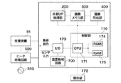
図2は、図1のプリンタにおける制御部の概略構成を示すブロック図である。なお、図示例は、本発明に関わる部分と主要な機能部のみが記載されており、その他の構成要素や機能部については省略されている。 FIG. 2 is a block diagram showing a schematic configuration of a control unit in the printer of FIG. In the illustrated example, only a portion related to the present invention and main functional units are described, and other components and functional units are omitted.
図2において、制御部110は、プリンタ全体を制御する基本制御部であり、CPU171と、ROM174と、RAM175とを備える。ROM174は、制御プログラム等が記憶されているメモリである。RAM175は、CPU171が制御プログラムを実行する際のワークメモリとして利用するメモリである。CPU171は、ROM174及びRAM175にアドレスバス、データバスを介して接続されている。
In FIG. 2, the
CPU171は、I/Oポート173を介して、モータやクラッチ等の各種負荷(不図示)、紙の位置を検知するためのセンサ類(不図示)、及び温度検知回路700に接続されている。I/Oポート173には、定着装置16と、定着装置内の定着ヒータ(不図示)へAC電源550の電力を供給するヒータ給電回路500が接続されており、CPU171がこれらの制御を行う。即ち、CPU171は、ROM174から読み出した制御プログラムを実行することで、I/Oポート173を介して順次入出力の制御を行い、定着装置16内の定着ヒータの温度制御を実行する。
The
温度検知回路700は、I/Oポート173を介して、定着装置内の温度センサ(不図示)から出力される温度検出信号が入力される。また、温度検知回路700は、ヒータ給電回路500へ制御信号を出力する。
The
CPU171は、画面表示を行う表示部(不図示)やキー入力部(不図示)を備える操作部172に接続されており、操作部172上の表示画面やキー入力を制御する。操作者は、キー入力部を操作することで、画像形成動作モードや表示の切り替えをCPU171に指示する。その結果、CPU171は、プリンタの状態やキー入力による動作モード設定の表示を行う。
The
また、CPU171は、外部I/F処理部200と、画像メモリ部300と、画像形成部400に接続されている。なお、画像形成部400には、図1の画像形成部1Y〜1Bkが含まれる。
The
外部I/F処理部200は、PCなどの外部機器から画像データや処理データなどを送受信する。画像メモリ部300は、画像を伸張処理や一時的に蓄積処理などをする画像形成部400は、上述した画像形成部1Y〜1Bkを備え、画像メモリ部300から転送されたライン画像データを露光装置7に露光させるべく処理を行う。
The external I /
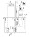
図3は、図2のヒータ給電回路500の概略構成と接続関係を示す図である。
FIG. 3 is a diagram showing a schematic configuration and connection relationship of the heater
定着装置16は、トナー像を加熱して定着させるための加熱源である定着ヒータ601と、定着ヒータ601の近傍に配置され、該定着ヒータ601の温度を検出するためのサーミスタなどの温度センサ602とを備える。なお、定着装置16は加圧ローラ等も備えるが、それらについては省略する。
The fixing
温度検出手段である温度センサ602は、制御部110と温度検知回路700に接続されている。温度センサ602から出力される温度検出信号604は、制御部110と温度検知回路700に入力される。定着ヒータ601は、その両端がヒータ給電回路500に接続されている。
A
ヒータ給電回路500は、定着ヒータ601の両端へのAC電源550からの電力供給を供給/遮断するための第1のリレー501と第2のリレー502を備える。第1のリレー501は、その一端が定着ヒータ601の一端に接続し、他端がAC電源550に接続されている。第2のリレー502は、その一端が半導体SW510を介して定着ヒータ601の他の一端に接続し、他端がAC電源550に接続されている。第1のリレー501及び第2のリレー502は、リレー制御手段としての制御部110から出力される制御信号503,504により、それぞれON/OFF制御される。制御部110から出力される制御信号503,504は、上述した図2のI/Oポート173を介して、第1のAND回路702、第2のAND回路703にそれぞれ入力される。
The heater
ゼロクロス検知回路505は、図示のように接続され、定着ヒータ601及びAC電源550に並列に接続されている。ゼロクロス検知回路505は、第1のリレー501及び第2のリレー502を介してAC電源550から電力が供給されると、交流波形のゼロクロスタイミングに応じたゼロクロス信号506(検知信号)を制御部110に出力する(電圧検知手段)。ゼロクロス検知回路505から出力されるゼロクロス信号506は、上述した図2のI/Oポート173を介して制御部110に入力される。
The zero
半導体SW510は、定着ヒータ601へ電力を供給するための経路上に配置され、第1のリレー501及び第2のリレー502のON/OFFとは無関係に、定着ヒータ601へ給電をON/OFFすることができるトライアック(登録商標)等の半導体スイッチである。また、半導体SW510は、制御部110から出力される制御信号512に応じてON/OFF制御される。
The
制御部110は、温度センサ602からの温度検出信号604に応じて制御信号512を出力し、半導体SW510をON/OFF制御することで定着ヒータ601の温調制御を行う。
The
第1のAND回路702は、制御部110から出力される制御信号503と温度検知回路700から出力される制御信号701に基づいて論理積(AND)演算を行い、第1のリレー501に第1のAND信号704を出力する論理回路である。一方、第2のAND回路703は、制御部110から出力される制御信号504と温度検知回路700から出力される制御信号701に基づいて論理積(AND)演算を行い、第2のリレー502に第2のAND信号705を出力する論理回路である。そのため、制御部110及び温度検知回路700のいずれか一方及び両方から第1のリレー501、第2のリレー502をOFFする制御信号が出力されると、いずれのリレーもOFFされる仕組みとなっている。
The first AND
制御部110は、温度センサ602からの温度検出信号604をもとに定着ヒータ601の温調制御を行う。制御部110は、温度検出信号604から検出した温度が閾値Tmax1以上であると判定した場合、定着ヒータ601が適正な温度から上昇したと判断して、定着ヒータ601への給電を停止する。即ち、制御部110は、半導体SW510をOFFするための制御信号512を出力すると共に、第1のリレー501及び第2のリレー502をOFFするための制御信号503,504を出力する。
The
一方、温度検知回路700は、ヒータ温度異常検出手段として機能し、温度センサ602からの温度検出信号604をもとに定着ヒータへの給電を停止させることができる。即ち、温度検知回路700は、温度検出信号604に示すヒータ温度が閾値Tmax2以上であると判定した場合、定着ヒータ601の異常発熱と判断して、定着ヒータ601への給電を停止するための制御信号701を出力する。
On the other hand, the
第1のAND回路702及び第2のAND回路703をOFFするための制御信号701を出力することで、ONするための制御信号503,504が制御部110から入力されていても、第1及び第2のリレーをONするための信号が出力されなくなる。その結果、第1のリレー501及び第2のリレー502がOFFされ、定着ヒータ601への給電が停止する。
By outputting a
上述した閾値Tmax1,Tmax2は、Tmax2>Tmax1の関係にある。これにより、制御部110内のCPU171に暴走等の何らかの異常が発生して温調制御ができなくなった場合でも、温度検知回路700により、定着ヒータ601への給電を停止することができる。その結果、定着ヒータ601や周囲の部品を保護すると共に、定着異常等を回避することができる。
The threshold values Tmax1 and Tmax2 described above have a relationship of Tmax2> Tmax1. Thus, even when some abnormality such as runaway occurs in the
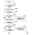
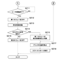
図4A及び図4Bは、第1及び第2のリレーの接点融着を検知するための処理の流れを示すフローチャートである。 4A and 4B are flowcharts showing the flow of processing for detecting contact fusion of the first and second relays.
図4Aにおいて、ステップS201では、制御部110は、定着ヒータ601への通電を開始するか否かを判断する。通電を開始する場合、通電を開始する前に、制御部110は、第1のAND回路702をONするための制御信号503を出力し、第1のAND回路702から出力される第1のAND信号704により第1のリレー501をONする(ステップS202)。その後、制御部110は所定時間(例えば、100ms)待機する(ステップS203)。これは、第1のリレー501がメカニカルなリレーであるため、接点接続の安定を待つためのものである。
4A, in step S201,
次に、ステップS204では、制御部110は、ゼロクロス検知回路505からのゼロクロス信号506を検知したか否かを判断する。ゼロクロス信号506を検知した場合(ステップS204でYES)、ステップS205へ移行する。
Next, in step S <b> 204, the
ステップS205において、制御部110は、第2のリレー502をONするための制御信号504を出力していないにも関わらず、ゼロクロス信号506が検知されていることから、第2のリレー502に接点融着等の故障が発生して通電状態にあると判断する。ステップS205は第1の判断手段の一例である。そして、制御部110は、図1のプリンタの動作を停止し(ステップS217)、操作部172上の表示部にエラーメッセージを表示させ(ステップS218)、本処理を終了する。
In step S205, the
一方、ステップS204において、制御部110は、ゼロクロス信号506を検知していない場合(ステップS204でNO)、ステップS206へ進む。
On the other hand, when the zero
ステップS206では、制御部110は、第1のAND回路703をONするための制御信号504を出力し、第2のAND回路703から出力される第2のAND信号705により第2のリレー502をONする。ステップS206は第1の制御手段の一例である。第2のリレー502をONさせた後、制御部110は所定時間(例えば、100ms)待機する(ステップS207)。これはステップS203で説明した理由と同じである。
In step S <b> 206, the
次に、ステップS208では、制御部110は、ステップS204と同様に、ゼロクロス検知回路505からのゼロクロス信号506を検知したか否かを判断する。ゼロクロス信号506を検知していない場合(ステップS208でNO)、ステップS209へ移行する。
Next, in step S208, the
ステップS209において、制御部110は、第1のリレー501及び第2のリレー502の両方をONしたにもかかわらず通電が行われていないことから、第1のリレー501及び第2のリレー502の導通不良等の故障が発生して通電状態にないと判断する。この故障は、第1のリレー501及び第2のリレー502のどちらか一方の導通不良であっても、両方の導通不良であっても検知可能である。ステップS209は第3の判断手段の一例である。導通不良等の故障が発生したと判断すると、制御部110は、ステップS217以降の処理を行って本処理を終了する。
In step S209, since the
一方、ステップS208において、制御部110は、ゼロクロス信号506を検知した場合、第1のリレー501及び第2のリレー502が正常に動作すると判断し、定着ヒータ601の通電を開始させ(ステップS210)、画像形成動作が可能となる。ステップS210では、制御部110は、半導体SW510をONするための制御信号512を出力することで定着ヒータ601への通電を開始する。
On the other hand, when the zero
図4Bにおいて、画像形成動作が終了すると、制御部110は、定着ヒータ601への通電を終了するか否かを判断する(ステップS211)。通電を終了する場合は、制御部110は、第1のAND回路702をOFFするための制御信号503を出力し、第1のAND回路702から出力される第1のAND信号704により第1のリレー501をOFFする(ステップS212)。その後、制御部110は、所定時間(例えば、100ms)待機(ステップS213)した後、ゼロクロス信号506を検知したか否かを判断する(ステップS214)。ゼロクロス信号506を検知した場合(ステップS214でYES)、ステップS215へ移行する。
In FIG. 4B, when the image forming operation ends, the
ステップS215では、制御部110は、第1のリレー501をONするための制御信号503を出力していないにも関わらず、ゼロクロス信号506が検知されていることから、第1のリレー501の接点融着等の故障が発生して通電状態にあると判断する。ステップS215は第2の判断手段の一例である。そして、制御部110は、ステップS217以降の処理を行って本処理を終了する。
In step S215, the
一方、ステップS214において、制御部110は、ゼロクロス信号506を検知していない場合(ステップS214でNO)、ステップS216へ移行する。
On the other hand, if the zero
ステップS216では、制御部110は、第2のAND回路703をOFFするための制御信号504を出力し、第2のAND回路703から出力される第2のAND信号705により第2のリレー502をOFFする。ステップS216は第2の制御手段の一例である。なお、第1のリレー501と第2のリレー502の位置が反対であっても、上記処理が適用可能である。
In step S216, the
温度検知回路700は、ステップS210で通電が開始された後、温度センサ602からの温度検出信号604をもとに定着ヒータへの給電を停止させる。即ち、温度検知回路700が、温度センサ602で検出されたヒータ温度が閾値Tmax2以上であると判定した場合、定着ヒータ601の異常発熱と判断し、定着ヒータ601への給電を停止するための制御信号701を出力する。
The
また、制御部110も、ステップS210で通電が開始された後、温度センサ602からの温度検出信号604をもとに定着ヒータ601への給電を停止させる。即ち、制御部110が、温度センサ602で検出されたヒータ温度が閾値Tmax1以上であると判定した場合、定着ヒータ601が適正な温度から上昇したと判断し、定着ヒータ601への給電を停止するための制御信号503,504を出力する。
The
上記実施形態によれば、制御部110は、定着ヒータ601への通電を開始する前に第1のリレー501をONするように制御信号を出力し、ゼロクロス検知回路505で入力電圧が検知されてない場合、第2のリレー502をONするように制御信号を出力する。第1のリレー501がONされたときにゼロクロス検知回路505により入力電圧が検知された場合は、第2のリレーが故障していると判断する。定着ヒータ601への通電を終了する前に第1のリレー501をOFFするように制御信号を出力し、ゼロクロス検知回路505により入力電圧が検知されていない場合、第2のリレー502をOFFするように制御信号を出力する。第1のリレー501がOFFされたときにゼロクロス検知回路505により入力電圧が検知された場合は、第1のリレー501が故障していると判断する。これにより、定着ヒータの両端にそれぞれリレーが接続された回路構成において、各リレーで発生した接点融着を個別に検出できる。
According to the above embodiment, the
このように、二つのリレーの動作タイミングをずらすことで、それぞれのリレーの接点融着を確実に検知することが可能になる。その結果、リレーの接点融着の有無の検知を、一方はリレーON時、もう一方はリレーOFF時に実施することで二つのリレーの接点融着検知にかかる時間を低減させることが可能になる。 Thus, by shifting the operation timing of the two relays, it becomes possible to reliably detect contact fusion of each relay. As a result, it is possible to reduce the time required to detect contact fusion between the two relays by detecting whether or not the relay contacts are fused, one when the relay is ON and the other when the relay is OFF.
また、本発明は、以下の処理を実行することによっても実現される。即ち、上述した実施形態の機能を実現するソフトウェア(プログラム)を、ネットワーク又は各種記憶媒体を介してシステム或いは装置に供給し、そのシステム或いは装置のコンピュータ(またはCPUやMPU等)がプログラムを読み出して実行する処理である。 The present invention can also be realized by executing the following processing. That is, software (program) that realizes the functions of the above-described embodiments is supplied to a system or apparatus via a network or various storage media, and a computer (or CPU, MPU, or the like) of the system or apparatus reads the program. It is a process to be executed.
1Y,1M,1C,1Bk 画像形成部
16 定着装置
110 制御部
171 CPU
500 ヒータ給電回路
505 ゼロクロス検知回路
601 定着ヒータ
602 温度センサ
700 温度検知回路
1Y, 1M, 1C, 1Bk
500 Heater
Claims (6)
前記リレー制御手段は、
前記ヒータへの通電を開始する前に前記第1のリレーをONするように前記制御信号を出力し、前記電圧検知手段により入力電圧が検知されていない場合、前記第2のリレーをONするように前記制御信号を出力する第1の制御手段と、
前記第1の制御手段により前記第1のリレーがONされたときに前記電圧検知手段により入力電圧が検知された場合は、前記第2のリレーが故障していると判断する第1の判断手段と、
前記ヒータへの通電を終了する前に前記第1のリレーをOFFするように前記制御信号を出力し、前記電圧検知手段により入力電圧が検知されていない場合、前記第2のリレーをOFFするように前記制御信号を出力する第2の制御手段と、
前記第2の制御手段により前記第1のリレーがOFFされたときに前記電圧検知手段により入力電圧が検知された場合は、前記第1のリレーが故障していると判断する第2の判断手段とを備えることを特徴とする画像形成装置。 A heater, a first relay and a second relay respectively connected to both ends of the heater, and the heater on each path from the first relay to the heater and from the second relay to the heater; An image forming apparatus comprising: voltage detection means for detecting the presence or absence of an input voltage; and relay control means for outputting a control signal for turning on / off each of the first relay and the second relay.
The relay control means includes
Before starting energization of the heater, the control signal is output so as to turn on the first relay, and when the input voltage is not detected by the voltage detecting means, the second relay is turned on. First control means for outputting the control signal to:
First determination means for determining that the second relay has failed when the input voltage is detected by the voltage detection means when the first relay is turned on by the first control means. When,
Before the energization of the heater is finished, the control signal is output so as to turn off the first relay, and when the input voltage is not detected by the voltage detection means, the second relay is turned off. Second control means for outputting the control signal to
Second determination means for determining that the first relay has failed when the input voltage is detected by the voltage detection means when the first relay is turned off by the second control means. An image forming apparatus comprising:
前記第1の制御手段により前記第2のリレーがONするように前記制御信号が出力された後、前記電圧検知手段により入力電圧が検知されなかった場合は、前記第1及び前記第2のリレーがともに故障していると判断する第3の判断手段をさらに備えることを特徴とする請求項1記載の画像形成装置。 The relay control means includes
After the control signal is output so that the second relay is turned on by the first control means, if the input voltage is not detected by the voltage detection means, the first and second relays The image forming apparatus according to claim 1, further comprising: a third determination unit that determines that both are malfunctioning.
前記ヒータの温度を検出して温度検出信号を前記リレー制御手段に出力する温度検出手段とをさらに備え、
前記リレー制御手段は、前記温度検出信号に基づいて前記スイッチ手段を制御することで前記ヒータの温調制御を行うことを特徴とする請求項1乃至4のいずれか1項に記載の画像形成装置。 Switch means arranged on a path for supplying electric power to the heater, and turned ON / OFF according to a control signal from the relay control means;
Temperature detecting means for detecting the temperature of the heater and outputting a temperature detection signal to the relay control means;
5. The image forming apparatus according to claim 1, wherein the relay control unit controls the temperature of the heater by controlling the switch unit based on the temperature detection signal. 6. .
前記ヒータ温度異常検出手段は、前記ヒータの温度が所定の温度を超えたと判断した場合、前記第1のリレー及び前記第2のリレーをOFFするための制御信号を出力することを特徴とした請求項4記載の画像形成装置。 Further comprising a heater temperature abnormality detection means for determining whether the temperature of the heater exceeds a predetermined temperature from a temperature detection signal output from the temperature detection means,
The heater temperature abnormality detecting means outputs a control signal for turning off the first relay and the second relay when it is determined that the temperature of the heater exceeds a predetermined temperature. Item 5. The image forming apparatus according to Item 4.
前記演算手段は、前記ヒータ温度異常検出手段または前記リレー制御手段のいずれか一方から前記第1のリレー及び前記第2のリレーをOFFするための制御信号を入力したときは、前記第1のリレー及び前記第2のリレーをOFFする信号を出力することを特徴とする請求項5記載の画像形成装置。 A calculation means for calculating a logical product of the control signal from the heater temperature abnormality detection means and the control signal from the relay control means;
When the control means inputs a control signal for turning off the first relay and the second relay from either the heater temperature abnormality detection means or the relay control means, the first relay 6. The image forming apparatus according to claim 5, wherein a signal for turning off the second relay is output.
Priority Applications (2)
| Application Number | Priority Date | Filing Date | Title |
|---|---|---|---|
| JP2010106404A JP5460455B2 (en) | 2010-05-06 | 2010-05-06 | Image forming apparatus |
| US13/098,730 US8983314B2 (en) | 2010-05-06 | 2011-05-02 | Image forming apparatus capable of detecting contact fusion, and relay control apparatus |
Applications Claiming Priority (1)
| Application Number | Priority Date | Filing Date | Title |
|---|---|---|---|
| JP2010106404A JP5460455B2 (en) | 2010-05-06 | 2010-05-06 | Image forming apparatus |
Publications (3)
| Publication Number | Publication Date |
|---|---|
| JP2011237480A true JP2011237480A (en) | 2011-11-24 |
| JP2011237480A5 JP2011237480A5 (en) | 2013-06-20 |
| JP5460455B2 JP5460455B2 (en) | 2014-04-02 |
Family
ID=44902008
Family Applications (1)
| Application Number | Title | Priority Date | Filing Date |
|---|---|---|---|
| JP2010106404A Active JP5460455B2 (en) | 2010-05-06 | 2010-05-06 | Image forming apparatus |
Country Status (2)
| Country | Link |
|---|---|
| US (1) | US8983314B2 (en) |
| JP (1) | JP5460455B2 (en) |
Cited By (12)
| Publication number | Priority date | Publication date | Assignee | Title |
|---|---|---|---|---|
| JP2014010307A (en) * | 2012-06-29 | 2014-01-20 | Canon Inc | Image forming apparatus |
| JP2016073015A (en) * | 2014-09-26 | 2016-05-09 | キヤノン株式会社 | Power supply apparatus and image forming apparatus |
| WO2017043202A1 (en) * | 2015-09-08 | 2017-03-16 | キヤノン株式会社 | Image forming device |
| JP2017083888A (en) * | 2012-02-09 | 2017-05-18 | 株式会社リコー | Fixing apparatus and image forming apparatus |
| JP2018054189A (en) * | 2016-09-28 | 2018-04-05 | 株式会社ノーリツ | Hot water device |
| US9983526B2 (en) | 2012-02-09 | 2018-05-29 | Ricoh Company, Ltd. | Fixing device and image forming apparatus including same |
| CN108803285A (en) * | 2017-04-27 | 2018-11-13 | 日本冲信息株式会社 | Image forming apparatus |
| JP2019105664A (en) * | 2017-12-08 | 2019-06-27 | キヤノン株式会社 | Power supply device and image forming apparatus |
| JP2021113921A (en) * | 2020-01-20 | 2021-08-05 | キヤノン株式会社 | Image forming apparatus and heater control device |
| JP2022046883A (en) * | 2020-09-11 | 2022-03-24 | 日立グローバルライフソリューションズ株式会社 | Heating cooker |
| JP2022078416A (en) * | 2020-11-13 | 2022-05-25 | 日立グローバルライフソリューションズ株式会社 | Cooker |
| JP2022134309A (en) * | 2021-03-03 | 2022-09-15 | アズビル株式会社 | Heater controller and vacuum gauge |
Families Citing this family (7)
| Publication number | Priority date | Publication date | Assignee | Title |
|---|---|---|---|---|
| JP5948922B2 (en) * | 2012-02-08 | 2016-07-06 | ブラザー工業株式会社 | Image forming apparatus |
| JP5712186B2 (en) * | 2012-10-31 | 2015-05-07 | 京セラドキュメントソリューションズ株式会社 | Status detection apparatus and image forming apparatus having the same |
| US9897656B2 (en) | 2013-05-16 | 2018-02-20 | Carrier Corporation | Method for sensing welded contacts on a switching device |
| KR101551088B1 (en) * | 2014-05-09 | 2015-09-07 | 현대자동차주식회사 | Apparatus and Method for detecting fault of battery heating system and relay |
| CN106856321B (en) * | 2015-12-08 | 2019-11-05 | 太琦科技股份有限公司 | Bathing safety control system and bathing safety control method |
| US10795300B2 (en) * | 2019-01-07 | 2020-10-06 | Canon Kabushiki Kaisha | Image forming apparatus |
| GB2629493B (en) * | 2021-04-30 | 2025-05-21 | Dyson Technology Ltd | Heating appliance |
Citations (14)
| Publication number | Priority date | Publication date | Assignee | Title |
|---|---|---|---|---|
| JPH0334005A (en) * | 1989-06-30 | 1991-02-14 | Kyocera Corp | Method and circuit for detecting abnormality of temperature controller |
| JPH0553475A (en) * | 1991-08-27 | 1993-03-05 | Ricoh Co Ltd | Heat fixing device |
| JPH05112065A (en) * | 1991-10-24 | 1993-05-07 | Canon Inc | Image forming apparatus |
| JPH0619366A (en) * | 1992-06-30 | 1994-01-28 | Canon Inc | Image forming device |
| JPH09319251A (en) * | 1996-05-29 | 1997-12-12 | Canon Inc | Fixing control device |
| JP2002296955A (en) * | 2001-03-30 | 2002-10-09 | Copyer Co Ltd | Image forming device |
| JP2003255758A (en) * | 2002-03-06 | 2003-09-10 | Konica Corp | Image forming apparatus |
| JP2003295679A (en) * | 2002-03-29 | 2003-10-15 | Canon Inc | Image forming device |
| JP2003295644A (en) * | 2002-04-04 | 2003-10-15 | Canon Inc | Image forming device |
| JP2006058520A (en) * | 2004-08-19 | 2006-03-02 | Ricoh Co Ltd | Power supply circuit, power supply apparatus, and image forming apparatus |
| JP2008257190A (en) * | 2007-03-13 | 2008-10-23 | Ricoh Co Ltd | Power control device and image forming apparatus using power control device |
| JP2009168404A (en) * | 2008-01-18 | 2009-07-30 | Yamatake Corp | Control device for floor heating |
| JP2009300944A (en) * | 2008-06-17 | 2009-12-24 | Canon Inc | Heating unit and image forming apparatus |
| JP4572168B2 (en) * | 2003-03-31 | 2010-10-27 | 日本電気株式会社 | Method and apparatus for detecting welding of relay contacts |
Family Cites Families (3)
| Publication number | Priority date | Publication date | Assignee | Title |
|---|---|---|---|---|
| US4516076A (en) * | 1982-09-17 | 1985-05-07 | The Singer Company | Fault detection arrangement for relay switching system |
| JP3390638B2 (en) * | 1997-09-03 | 2003-03-24 | 松下電器産業株式会社 | Automotive air conditioning controller |
| JP3840097B2 (en) * | 2001-11-13 | 2006-11-01 | トヨタ自動車株式会社 | Power supply circuit device for vehicle |
-
2010
- 2010-05-06 JP JP2010106404A patent/JP5460455B2/en active Active
-
2011
- 2011-05-02 US US13/098,730 patent/US8983314B2/en active Active
Patent Citations (14)
| Publication number | Priority date | Publication date | Assignee | Title |
|---|---|---|---|---|
| JPH0334005A (en) * | 1989-06-30 | 1991-02-14 | Kyocera Corp | Method and circuit for detecting abnormality of temperature controller |
| JPH0553475A (en) * | 1991-08-27 | 1993-03-05 | Ricoh Co Ltd | Heat fixing device |
| JPH05112065A (en) * | 1991-10-24 | 1993-05-07 | Canon Inc | Image forming apparatus |
| JPH0619366A (en) * | 1992-06-30 | 1994-01-28 | Canon Inc | Image forming device |
| JPH09319251A (en) * | 1996-05-29 | 1997-12-12 | Canon Inc | Fixing control device |
| JP2002296955A (en) * | 2001-03-30 | 2002-10-09 | Copyer Co Ltd | Image forming device |
| JP2003255758A (en) * | 2002-03-06 | 2003-09-10 | Konica Corp | Image forming apparatus |
| JP2003295679A (en) * | 2002-03-29 | 2003-10-15 | Canon Inc | Image forming device |
| JP2003295644A (en) * | 2002-04-04 | 2003-10-15 | Canon Inc | Image forming device |
| JP4572168B2 (en) * | 2003-03-31 | 2010-10-27 | 日本電気株式会社 | Method and apparatus for detecting welding of relay contacts |
| JP2006058520A (en) * | 2004-08-19 | 2006-03-02 | Ricoh Co Ltd | Power supply circuit, power supply apparatus, and image forming apparatus |
| JP2008257190A (en) * | 2007-03-13 | 2008-10-23 | Ricoh Co Ltd | Power control device and image forming apparatus using power control device |
| JP2009168404A (en) * | 2008-01-18 | 2009-07-30 | Yamatake Corp | Control device for floor heating |
| JP2009300944A (en) * | 2008-06-17 | 2009-12-24 | Canon Inc | Heating unit and image forming apparatus |
Cited By (19)
| Publication number | Priority date | Publication date | Assignee | Title |
|---|---|---|---|---|
| JP2017083888A (en) * | 2012-02-09 | 2017-05-18 | 株式会社リコー | Fixing apparatus and image forming apparatus |
| US9983526B2 (en) | 2012-02-09 | 2018-05-29 | Ricoh Company, Ltd. | Fixing device and image forming apparatus including same |
| JP2014010307A (en) * | 2012-06-29 | 2014-01-20 | Canon Inc | Image forming apparatus |
| JP2016073015A (en) * | 2014-09-26 | 2016-05-09 | キヤノン株式会社 | Power supply apparatus and image forming apparatus |
| WO2017043202A1 (en) * | 2015-09-08 | 2017-03-16 | キヤノン株式会社 | Image forming device |
| JP2017053966A (en) * | 2015-09-08 | 2017-03-16 | キヤノン株式会社 | Image forming apparatus |
| US10146164B2 (en) | 2015-09-08 | 2018-12-04 | Canon Kabushiki Kaisha | Image forming apparatus |
| JP2018054189A (en) * | 2016-09-28 | 2018-04-05 | 株式会社ノーリツ | Hot water device |
| JP2018185462A (en) * | 2017-04-27 | 2018-11-22 | 株式会社沖データ | Image forming apparatus |
| CN108803285A (en) * | 2017-04-27 | 2018-11-13 | 日本冲信息株式会社 | Image forming apparatus |
| CN108803285B (en) * | 2017-04-27 | 2022-06-17 | 冲电气工业株式会社 | Image forming apparatus with a toner supply device |
| JP2019105664A (en) * | 2017-12-08 | 2019-06-27 | キヤノン株式会社 | Power supply device and image forming apparatus |
| JP2021113921A (en) * | 2020-01-20 | 2021-08-05 | キヤノン株式会社 | Image forming apparatus and heater control device |
| JP7455592B2 (en) | 2020-01-20 | 2024-03-26 | キヤノン株式会社 | Image forming device |
| JP2022046883A (en) * | 2020-09-11 | 2022-03-24 | 日立グローバルライフソリューションズ株式会社 | Heating cooker |
| JP7341108B2 (en) | 2020-09-11 | 2023-09-08 | 日立グローバルライフソリューションズ株式会社 | heating cooker |
| JP2022078416A (en) * | 2020-11-13 | 2022-05-25 | 日立グローバルライフソリューションズ株式会社 | Cooker |
| JP2022134309A (en) * | 2021-03-03 | 2022-09-15 | アズビル株式会社 | Heater controller and vacuum gauge |
| JP7640287B2 (en) | 2021-03-03 | 2025-03-05 | アズビル株式会社 | Heater control device and vacuum gauge |
Also Published As
| Publication number | Publication date |
|---|---|
| JP5460455B2 (en) | 2014-04-02 |
| US20110274450A1 (en) | 2011-11-10 |
| US8983314B2 (en) | 2015-03-17 |
Similar Documents
| Publication | Publication Date | Title |
|---|---|---|
| JP5460455B2 (en) | Image forming apparatus | |
| JP5424012B2 (en) | Fixing device control method, fixing device, and image forming apparatus | |
| JP5300518B2 (en) | Image forming apparatus | |
| JP5089146B2 (en) | Image heating apparatus and image forming apparatus | |
| JP5320321B2 (en) | Image forming apparatus | |
| JP4564769B2 (en) | Image forming apparatus | |
| JP2015102833A (en) | Image forming apparatus | |
| JP5558696B2 (en) | Fixing apparatus and image forming apparatus | |
| JP2015099269A (en) | Image forming apparatus | |
| JP6570338B2 (en) | Image forming apparatus | |
| JP2009237328A (en) | Image forming apparatus | |
| JP2013105157A (en) | Fixing device, image forming apparatus, and fixing control method | |
| JP2009069558A (en) | Image forming apparatus | |
| JP2015145992A (en) | image forming apparatus | |
| JP2013125256A (en) | Image forming apparatus | |
| JP4082045B2 (en) | Image forming apparatus | |
| JP6598604B2 (en) | Image forming apparatus | |
| JP4381758B2 (en) | Image forming apparatus | |
| JP2007109487A (en) | Heater control device and image forming apparatus | |
| JP5346860B2 (en) | Image forming apparatus | |
| JP5558947B2 (en) | Image forming apparatus | |
| JP2006171553A (en) | Image forming apparatus | |
| JP2004304866A (en) | Power supply device and image forming apparatus | |
| JP2019012208A (en) | Image forming apparatus | |
| JP2017177377A (en) | Power source control device and image formation device |
Legal Events
| Date | Code | Title | Description |
|---|---|---|---|
| A521 | Request for written amendment filed |
Free format text: JAPANESE INTERMEDIATE CODE: A523 Effective date: 20130502 |
|
| A621 | Written request for application examination |
Free format text: JAPANESE INTERMEDIATE CODE: A621 Effective date: 20130502 |
|
| A977 | Report on retrieval |
Free format text: JAPANESE INTERMEDIATE CODE: A971007 Effective date: 20131209 |
|
| TRDD | Decision of grant or rejection written | ||
| A01 | Written decision to grant a patent or to grant a registration (utility model) |
Free format text: JAPANESE INTERMEDIATE CODE: A01 Effective date: 20131217 |
|
| A61 | First payment of annual fees (during grant procedure) |
Free format text: JAPANESE INTERMEDIATE CODE: A61 Effective date: 20140114 |
|
| R151 | Written notification of patent or utility model registration |
Ref document number: 5460455 Country of ref document: JP Free format text: JAPANESE INTERMEDIATE CODE: R151 |