JP2011237408A - Biological information measuring device, lighting method in the same and biological information measuring method - Google Patents
Biological information measuring device, lighting method in the same and biological information measuring method Download PDFInfo
- Publication number
- JP2011237408A JP2011237408A JP2011057911A JP2011057911A JP2011237408A JP 2011237408 A JP2011237408 A JP 2011237408A JP 2011057911 A JP2011057911 A JP 2011057911A JP 2011057911 A JP2011057911 A JP 2011057911A JP 2011237408 A JP2011237408 A JP 2011237408A
- Authority
- JP
- Japan
- Prior art keywords
- biological information
- light
- unit
- light source
- measuring device
- Prior art date
- Legal status (The legal status is an assumption and is not a legal conclusion. Google has not performed a legal analysis and makes no representation as to the accuracy of the status listed.)
- Pending
Links
Images

Classifications
-
- A—HUMAN NECESSITIES
- A61—MEDICAL OR VETERINARY SCIENCE; HYGIENE
- A61B—DIAGNOSIS; SURGERY; IDENTIFICATION
- A61B5/00—Measuring for diagnostic purposes; Identification of persons
- A61B5/145—Measuring characteristics of blood in vivo, e.g. gas concentration or pH-value ; Measuring characteristics of body fluids or tissues, e.g. interstitial fluid or cerebral tissue
- A61B5/14532—Measuring characteristics of blood in vivo, e.g. gas concentration or pH-value ; Measuring characteristics of body fluids or tissues, e.g. interstitial fluid or cerebral tissue for measuring glucose, e.g. by tissue impedance measurement
-
- A—HUMAN NECESSITIES
- A61—MEDICAL OR VETERINARY SCIENCE; HYGIENE
- A61B—DIAGNOSIS; SURGERY; IDENTIFICATION
- A61B5/00—Measuring for diagnostic purposes; Identification of persons
- A61B5/14—Devices for taking samples of blood ; Measuring characteristics of blood in vivo, e.g. gas concentration within the blood, pH-value of blood
-
- A—HUMAN NECESSITIES
- A61—MEDICAL OR VETERINARY SCIENCE; HYGIENE
- A61B—DIAGNOSIS; SURGERY; IDENTIFICATION
- A61B5/00—Measuring for diagnostic purposes; Identification of persons
- A61B5/15—Devices for taking samples of blood
- A61B5/157—Devices characterised by integrated means for measuring characteristics of blood
-
- G—PHYSICS
- G01—MEASURING; TESTING
- G01N—INVESTIGATING OR ANALYSING MATERIALS BY DETERMINING THEIR CHEMICAL OR PHYSICAL PROPERTIES
- G01N33/00—Investigating or analysing materials by specific methods not covered by groups G01N1/00 - G01N31/00
- G01N33/48—Biological material, e.g. blood, urine; Haemocytometers
- G01N33/483—Physical analysis of biological material
- G01N33/487—Physical analysis of biological material of liquid biological material
- G01N33/4875—Details of handling test elements, e.g. dispensing or storage, not specific to a particular test method
-
- A—HUMAN NECESSITIES
- A61—MEDICAL OR VETERINARY SCIENCE; HYGIENE
- A61B—DIAGNOSIS; SURGERY; IDENTIFICATION
- A61B2560/00—Constructional details of operational features of apparatus; Accessories for medical measuring apparatus
- A61B2560/04—Constructional details of apparatus
- A61B2560/0406—Constructional details of apparatus specially shaped apparatus housings
-
- A—HUMAN NECESSITIES
- A61—MEDICAL OR VETERINARY SCIENCE; HYGIENE
- A61B—DIAGNOSIS; SURGERY; IDENTIFICATION
- A61B2560/00—Constructional details of operational features of apparatus; Accessories for medical measuring apparatus
- A61B2560/04—Constructional details of apparatus
- A61B2560/0443—Modular apparatus
-
- A—HUMAN NECESSITIES
- A61—MEDICAL OR VETERINARY SCIENCE; HYGIENE
- A61B—DIAGNOSIS; SURGERY; IDENTIFICATION
- A61B2562/00—Details of sensors; Constructional details of sensor housings or probes; Accessories for sensors
- A61B2562/02—Details of sensors specially adapted for in-vivo measurements
- A61B2562/0295—Strip shaped analyte sensors for apparatus classified in A61B5/145 or A61B5/157
Landscapes
- Health & Medical Sciences (AREA)
- Life Sciences & Earth Sciences (AREA)
- Engineering & Computer Science (AREA)
- Physics & Mathematics (AREA)
- Biomedical Technology (AREA)
- Molecular Biology (AREA)
- Biophysics (AREA)
- Pathology (AREA)
- General Health & Medical Sciences (AREA)
- Public Health (AREA)
- Medical Informatics (AREA)
- Surgery (AREA)
- Animal Behavior & Ethology (AREA)
- Heart & Thoracic Surgery (AREA)
- Hematology (AREA)
- Veterinary Medicine (AREA)
- Chemical & Material Sciences (AREA)
- Optics & Photonics (AREA)
- Urology & Nephrology (AREA)
- Emergency Medicine (AREA)
- Food Science & Technology (AREA)
- Medicinal Chemistry (AREA)
- Analytical Chemistry (AREA)
- Biochemistry (AREA)
- General Physics & Mathematics (AREA)
- Immunology (AREA)
- Measurement Of The Respiration, Hearing Ability, Form, And Blood Characteristics Of Living Organisms (AREA)
- Investigating Or Analysing Biological Materials (AREA)
Abstract
Description
本発明は、ユーザの生体情報を測定する測定装置、生体情報測定装置における照明方法および生体情報測定方法に関する。 The present invention relates to a measurement device that measures biological information of a user, an illumination method in the biological information measurement device, and a biological information measurement method.
糖尿病患者等、健康管理上、その血糖値を測定し、食事量や運動量をコントロールしなければならないユーザにとって、その測定装置の操作性や、測定に要する準備等は極めて大きな問題である。そこで、ユーザが日々の生活において比較的容易に、血糖値を測定できるように携帯型の測定装置が開発され、そこには血糖値管理を助ける様々な機能が搭載されている。一般に、携帯型の測定装置では、そのセンサーは使い捨てであり、測定ごとに新しいセンサーを測定装置に取り付けて、測定のための血液のセンサーへの点着を行う。そして、夜間等の比較的暗い場所での測定も容易に行えるように、血液の点着を行う領域の近傍を照らす照明装置を備えた測定装置の開発も行われている(たとえば、特許文献1を参照)。特許文献1に開示される測定装置では、発光ダイオード等を用いて、採血が行われるユーザの指をスポットライト式で照明する。
For users who have to measure their blood sugar levels and control their dietary and exercise levels for health management, such as diabetic patients, the operability of the measuring device and the preparations required for the measurement are extremely serious problems. In view of this, a portable measuring device has been developed so that the user can measure the blood sugar level relatively easily in daily life, and various functions for assisting blood sugar level management are installed therein. Generally, in a portable measurement device, the sensor is disposable, and a new sensor is attached to the measurement device for each measurement, and a blood sensor for measurement is spotted on the sensor. And the measurement apparatus provided with the illuminating device which illuminates the vicinity of the area | region where blood is spotted so that the measurement in a comparatively dark place, such as nighttime, can also be performed is also performed (for example, patent document 1). See). In the measurement apparatus disclosed in
血糖値等の生体情報を測定する装置が使用される状況を踏まえると、それは昼間に限られず夜間等の周囲が比較的暗い状況下で使用される機会も多い。そのため生体情報を測定するためのセンサーを装置本体に着脱する際の、ユーザの利便性は、測定装置自体の操作性に直結する課題である。一方で、携帯型の測定装置では特に言えることであるが、測定装置自体の消費電力を可能な限り抑制することが昨今の環境認識の高まりから求められている。 Considering the situation where a device for measuring biological information such as blood glucose level is used, it is not limited to daytime, and there are many occasions when the surroundings are relatively dark, such as at night. Therefore, the convenience of the user when attaching / detaching a sensor for measuring biological information to / from the apparatus main body is a problem directly related to the operability of the measuring apparatus itself. On the other hand, as is especially true for portable measuring devices, it is demanded to suppress the power consumption of the measuring device itself as much as possible from the recent increase in environmental awareness.
すなわち、従来技術のように、採血場所の照明を行う照明装置(発光ダイオード等)を測定装置に設置することでユーザの利便性は向上するが、その背反として消費電力が高くなり、携帯型の測定装置の電源寿命が短くなる。 That is, as in the prior art, the convenience of the user is improved by installing an illuminating device (such as a light-emitting diode) that illuminates the blood collection site in the measuring device. The power supply life of the measuring device is shortened.
本発明は、上記問題に鑑みてなされたものであり、ユーザの生体情報を測定する測定装置において、ユーザの利便性を向上させる照明機能を提供するとともに、測定装置としての消費電力の増加を可及的に抑制することを目的とする。 The present invention has been made in view of the above problems, and provides a lighting function that improves user convenience in a measuring apparatus that measures user biometric information, and can increase power consumption as a measuring apparatus. The purpose is to suppress as much as possible.
本発明においては、上記課題を解決するために、生体情報測定装置において既に何らかの構成のための光源として機能している光源部から発せられる光を、導光部材を介して、測定のためのセンサーが着脱される所定の場所へ導くこととした。これにより、センサーの着脱のために新たに光源を設ける必要が無く、測定装置おける消費電力がいたずらに上昇することを回避できる。 In the present invention, in order to solve the above-described problem, a sensor for measuring light emitted from a light source unit that is already functioning as a light source for some configuration in a biological information measuring device via a light guide member. It was decided to lead to a predetermined place where is attached and detached. Thereby, it is not necessary to provide a new light source for attaching and detaching the sensor, and it is possible to avoid an unnecessarily high power consumption in the measuring apparatus.
詳細には、本発明は、ユーザの生体情報を測定する生体情報測定装置であって、装置本体と、前記装置本体に設けられ、前記生体情報を測定するセンサーが着脱される着脱部と
、前記装置本体内において前記着脱部から離間した位置で、該着脱部以外の前記生体情報測定装置の構成のための光源として機能する光源部と、前記光源部によって照射された光を、前記センサーが着脱される前記着脱部近傍の所定位置まで導く導光部材と、を備える。
Specifically, the present invention relates to a biological information measuring device that measures a user's biological information, the device main body, an attachment / detachment unit that is provided in the device main body and that attaches / detaches the sensor that measures the biological information, The sensor attaches and detaches light emitted from the light source unit and a light source unit that functions as a light source for the configuration of the biological information measuring device other than the detachable unit at a position separated from the detachable unit in the apparatus main body. And a light guide member that leads to a predetermined position in the vicinity of the attaching / detaching portion.
本発明に係る生体情報測定装置は、例えば、測定のためのセンサーが、装置本体の着脱部に装着された状態で、そのセンサーに対して測定のための試料を点着、吸収等させることで、センサーから測定対象の生体情報に関する信号が装置本体に伝えられる。この信号を元に、装置本体側で最終的に求められている生体情報の生体情報が生成されることになる。このような構成の生体情報測定装置では、ユーザは所望の生体情報の測定を行うときには、センサーを着脱部に装着させ、また測定が終了したときはそのセンサーを抜き取る必要がある。したがって、ユーザの測定装置を操作する上で、センサーの装置本体への着脱操作は、測定装置の操作性、ユーザの利便性に大きく影響を及ぼす要素と考えられる。 The biological information measuring apparatus according to the present invention, for example, by spotting, absorbing, etc., a sample for measurement with respect to the sensor in a state where the sensor for measurement is attached to the detachable part of the apparatus main body. A signal related to biological information to be measured is transmitted from the sensor to the apparatus main body. Based on this signal, the biological information of the biological information finally obtained on the apparatus main body side is generated. In the biological information measuring apparatus having such a configuration, the user needs to attach the sensor to the detachable part when measuring desired biological information, and to remove the sensor when the measurement is completed. Therefore, when the user operates the measuring apparatus, the attaching / detaching operation of the sensor to / from the apparatus main body is considered to be an element that greatly affects the operability of the measuring apparatus and the convenience of the user.
ここで、上記生体情報測定装置では、光源部が、着脱部から離間した位置で、該着脱部以外の生体情報測定装置の構成のための光源として機能している。すなわち、当該光源部は、既に生体情報測定装置の一構成として組み込まれているものであり、上記課題を解決するために新たに装置内に組み込まれたものではない。したがって、生体情報計装置において、既に組み込まれて、何らかの光源として機能する構成は、上記光源部に相当する。 Here, in the biological information measuring device, the light source unit functions as a light source for the configuration of the biological information measuring device other than the detachable unit at a position separated from the detachable unit. That is, the light source unit is already incorporated as one configuration of the biological information measuring device, and is not newly incorporated in the device in order to solve the above problem. Therefore, in the biological information meter device, a configuration that is already incorporated and functions as a certain light source corresponds to the light source unit.
しかし、この光源部と着脱部の近傍の所定位置との間に導光部材が配置されることで、本来的には着脱部用の照明ではない光源部の光を、着脱部の近傍に導き、着脱部へのセンサーの装着、脱着を支援することができる。特に、この導光部材によって導かれた光は、周囲が暗い環境下でのユーザのセンサー脱着操作を効果的に支援するとともに、当該支援のための発光用に直接的に電力を消費する構成ではないため、生体情報測定装置としての消費電力をいたずらに上昇させることはない。また、所定位置は、いわば導光部材により伝えられた光がそこから照射され、センサーの脱着操作を支援できる位置であればどこでもよい。このような所定位置は、例えば、当該支援に適切な着脱部の近傍の位置である。なお、この所定位置には、着脱部そのものの位置も含まれてもよい。 However, the light guide member is disposed between the light source unit and a predetermined position in the vicinity of the detachable unit, so that light of the light source unit that is not originally illumination for the detachable unit is guided to the vicinity of the detachable unit. It is possible to support the attachment / detachment of the sensor to / from the attaching / detaching portion. In particular, the light guided by the light guide member effectively supports the user's sensor attaching / detaching operation in an environment where the surroundings are dark, and in a configuration that directly consumes power for light emission for the support. Therefore, the power consumption as the biological information measuring device is not increased unnecessarily. In addition, the predetermined position may be any position as long as the light transmitted from the light guide member is irradiated from the predetermined position and can support the detaching operation of the sensor. Such a predetermined position is, for example, a position in the vicinity of the attachment / detachment part suitable for the support. The predetermined position may include the position of the detachable part itself.
上記生体情報測定装置において、前記センサーを介して測定された生体情報を表示するディスプレイを、更に備える構成とし、その場合、前記光源部は、前記ディスプレイの光源として機能するバックライトであってもよい。当該バックライトは、ユーザがディスプレイ上の表示を見やすくするための光源であり、すなわち測定装置内に既に組み込まれている構成である。そこで、このような構成を有する生体情報測定装置においては、バックライトが発光する光を導光部材によって上記所定位置まで導くことで、新たに光源を設けることなく、上記所定位置の照明を確保することができる。 The biological information measuring apparatus may further include a display that displays biological information measured through the sensor, and in this case, the light source unit may be a backlight that functions as a light source of the display. . The backlight is a light source that makes it easy for the user to see the display on the display, that is, a configuration that is already incorporated in the measurement apparatus. Therefore, in the biological information measuring apparatus having such a configuration, the light emitted from the backlight is guided to the predetermined position by the light guide member, thereby ensuring illumination at the predetermined position without newly providing a light source. be able to.
この場合、前記着脱部は、前記装置本体の側面に設けられ、前記導光部材は、前記バックライトの光を前記所定位置に導く長さを有するように構成されてもよい。すなわち、導光部材の長さを適切なものとすることで、バックライトの光を、着脱部が設けられている離間した位置へ確実に運ぶことができる。 In this case, the attaching / detaching portion may be provided on a side surface of the apparatus main body, and the light guide member may be configured to have a length for guiding the light of the backlight to the predetermined position. That is, by making the length of the light guide member appropriate, it is possible to reliably carry the light of the backlight to a separated position where the detachable portion is provided.
また、上述までの生体情報測定装置において、ユーザが前記生体情報測定装置を操作するための操作部を、更に備える構成とし、その場合、前記操作部がユーザに操作されると、前記光源部による発光が行われ、前記導光部材によって前記所定位置へその光が導かれる構成であってもよい。すなわち、ユーザが操作部を介して生体情報測定装置を操作しようとする場合、その操作部への接触を契機として発光部による発光を行わせることで、センサーの脱着部への装着、そこからの脱着を容易に行うことが可能となる。 Moreover, in the biological information measuring device up to the above, an operation unit for the user to operate the biological information measuring device is further provided. In this case, when the operation unit is operated by the user, the light source unit The light may be emitted and the light guided to the predetermined position by the light guide member. That is, when the user intends to operate the biological information measuring device via the operation unit, the light emitting unit emits light triggered by the contact with the operation unit, so that the sensor can be attached to the attachment / detachment unit, Desorption can be easily performed.
また、上記生体情報測定装置において、前記センサーが前記着脱部に装着されると、前記光源部による発光が行われ、前記導光部材によって前記所定位置へその光が導かれる構成であってもよい。この構成によれば、センサーの装着後において導光部材を介して所定位置に光が導かれるため、ユーザは、装着後のセンサーに対する処置、たとえば生体試料の点着等を行いやすくなる。なお、この場合における光源部による発光は、センサーが着脱部に装着されると同時に、もしくは装着後に行われればよい。 The biological information measuring device may be configured such that when the sensor is attached to the attachment / detachment unit, the light source unit emits light and the light guide member guides the light to the predetermined position. . According to this configuration, since light is guided to a predetermined position through the light guide member after the sensor is mounted, the user can easily perform a treatment on the sensor after mounting, for example, spotting a biological sample. In this case, light emission by the light source unit may be performed at the same time as or after the sensor is mounted on the detachable unit.
また、上述までの生体情報測定装置において、前記生体情報測定装置は、ユーザの血糖値を測定する装置であり、その場合、前記着脱部には、ユーザの血液が点着されてその血糖値に応じた電流出力を出す血糖値測定用センサーが着脱される構成であってもよい。また、前記生体情報測定装置は、ユーザが携帯可能な装置であってもよい。これらは一例であり、本発明に係る生体情報測定装置は、このような態様に限定されない。 Further, in the biological information measuring device described above, the biological information measuring device is a device for measuring a user's blood glucose level, and in this case, the blood of the user is spotted on the detachable portion and the blood glucose level is adjusted. A configuration in which a blood glucose level measurement sensor that outputs a corresponding current output is attached or detached may be used. The biological information measurement device may be a device that can be carried by a user. These are merely examples, and the biological information measuring device according to the present invention is not limited to such an embodiment.
次に、本発明を生体情報測定装置における照明方法の側面から捉えることも可能である。すなわち、本発明は、装置本体と、ユーザの生体情報を測定するセンサーが、装置外部から前記装置本体に着脱される着脱部と、を有し、ユーザの生体情報を測定する生体情報測定装置において、該着脱部近傍の照明を行う照明方法であって、前記装置本体内において前記着脱部から離間した位置で、該着脱部以外の前記生体情報測定装置の構成のための光源として機能する光源部を発光させる第一ステップと、前記第一ステップで、前記光源部によって照射された光を、前記センサーが着脱される前記着脱部近傍の所定位置と該光源部との間に設けられた導光部材を介して、該所定位置まで導く第二ステップと、を含む。本発明に係る照明方法においても、上記生体情報測定装置の場合と同様に、センサーの着脱用に新たな光源を設けることなく、センサーの着脱時に照明を提供することができるため、生体情報測定装置での消費電力をいたずらに上昇させることなく、装置の操作性を向上し、利便性を高めることが可能となる。なお、上記生体情報測定装置について開示した技術的思想は、同様に本発明に係る照明方法にも適用可能である。 Next, it is possible to grasp the present invention from the aspect of the illumination method in the biological information measuring apparatus. That is, the present invention provides a biological information measuring apparatus for measuring a user's biological information, comprising: an apparatus main body; and a sensor for measuring biological information of the user, which is attached to and detached from the apparatus main body from the outside of the apparatus. An illumination method for illuminating the vicinity of the attachment / detachment unit, wherein the light source unit functions as a light source for the configuration of the biological information measuring device other than the attachment / detachment unit at a position separated from the attachment / detachment unit in the apparatus main body. A light guide provided between the light source unit and a predetermined position in the vicinity of the detachable part where the sensor is attached and detached. And a second step of leading to the predetermined position through the member. Also in the illumination method according to the present invention, as in the case of the biological information measuring device, it is possible to provide illumination when the sensor is attached / detached without providing a new light source for attaching / detaching the sensor. Thus, the operability of the apparatus can be improved and the convenience can be improved without unnecessarily increasing the power consumption in the apparatus. In addition, the technical idea disclosed about the said biological information measuring device is applicable also to the illumination method which concerns on this invention similarly.
また、本発明を生体情報測定装置を用いた生体情報の測定方法の側面から捉えることも可能である。すなわち、本発明は、装置本体と、ユーザの生体情報を測定するセンサーが、装置外部から前記装置本体に着脱される着脱部と、を有する生体情報測定装置において、ユーザの生体情報を測定する測定方法であって、前記装置本体内において前記着脱部から離間した位置で、該着脱部以外の前記生体情報測定装置の構成のための光源として機能する光源部を発光させる発光ステップと、前記発光ステップでの前記光源部が、前記着脱部近傍の所定位置と該光源部との間に設けられた導光部材に対して発光している状態で、前記着脱部への前記センサーの装着を受け付ける装着ステップと、を含む。本発明に係る測定方法においても、上記と同様に所定位置への照明が行われるため、センサーの装置本体への着脱が容易に行われ得る。 In addition, the present invention can be grasped from the aspect of a biological information measuring method using a biological information measuring device. That is, the present invention provides a measurement for measuring a user's biological information in a biological information measuring device having a device main body and a sensor for measuring the user's biological information, which is attached to and detached from the device main body from the outside of the device. A light emitting step of causing a light source unit functioning as a light source for the configuration of the biological information measuring device other than the attaching / detaching part to emit light at a position apart from the attaching / detaching part in the device main body; and the light emitting step The light source unit at the position where light is emitted to a light guide member provided between the light source unit and a predetermined position in the vicinity of the attachment / detachment unit, and the sensor is attached to the attachment / detachment unit. Steps. Also in the measurement method according to the present invention, since illumination at a predetermined position is performed in the same manner as described above, the sensor can be easily attached to and detached from the apparatus main body.
更に、本発明を別の生体情報測定方法の側面から捉えることも可能である。すなわち、本発明は、装置本体と、ユーザの生体情報を測定するセンサーが、装置外部から前記装置本体に着脱される着脱部と、を有する生体情報測定装置において、ユーザの生体情報を測定する測定方法であって、前記着脱部への前記センサーの装着を受け付ける装着ステップと、前記装着ステップにおいて前記センサーの装着が受け付けられると、前記装置本体内において前記着脱部から離間した位置で該着脱部以外の前記生体情報測定装置の構成のための光源として機能する光源部を、前記着脱部近傍の所定位置と該光源部との間に設けられた導光部材に対して発光させる発光ステップと、を含む。このように、センサーの装着受け付けを起点として導光部材に対する発光が行われることで、センサーの装着後においても導光部材を介して所定位置に光が導かれることになる。その結果、ユーザは、装着後のセンサーに対する処置、たとえば生体試料の点着等を行いやすくなる。なお、この場合における光源部による発光は、センサーが着脱部に装着されると同時に、もしくは装着受
付後のあるタイミングに行われればよい。
Furthermore, the present invention can be understood from the aspect of another biological information measuring method. That is, the present invention provides a measurement for measuring a user's biological information in a biological information measuring device having a device main body and a sensor for measuring the user's biological information, which is attached to and detached from the device main body from the outside of the device. A mounting step for receiving mounting of the sensor on the mounting / detaching portion, and when mounting of the sensor is received in the mounting step, the mounting body is located at a position apart from the mounting / detaching portion in the apparatus main body. A light emitting step for causing a light source part functioning as a light source for the configuration of the biological information measuring device to emit light to a light guide member provided between a predetermined position near the attaching / detaching part and the light source part, Including. As described above, light is emitted from the light guide member starting from reception of the sensor mounting, so that light is guided to a predetermined position through the light guide member even after the sensor is mounted. As a result, the user can easily perform a treatment on the sensor after mounting, for example, spotting a biological sample. In this case, light emission by the light source unit may be performed at the same time as the sensor is mounted on the detachable unit or at a certain timing after the mounting is accepted.
ユーザの生体情報を測定する測定装置において、ユーザの利便性を向上させる照明機能を提供するとともに、測定装置としての消費電力の増加を可及的に抑制することが可能となる。 In the measuring device that measures the user's biological information, it is possible to provide an illumination function that improves the convenience for the user and to suppress the increase in power consumption as a measuring device as much as possible.
以下に、図面を参照して本発明の実施形態に係る生体情報測定装置に相当する、血糖値測定装置について説明する。なお、以下の実施の形態の構成は例示であり、本発明はこの実施の形態の構成に限定されるものではない。 Hereinafter, a blood glucose level measuring apparatus corresponding to a biological information measuring apparatus according to an embodiment of the present invention will be described with reference to the drawings. In addition, the structure of the following embodiment is an illustration and this invention is not limited to the structure of this embodiment.
<血糖値測定装置の概略>
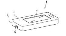
図1は、本発明に係る血糖値測定装置1の外観を示す図である。血糖値測定装置1は、糖尿病ユーザが自己でその血糖を測定できるように構成された携帯型の測定装置である。図に示すように、血糖値測定装置1はユーザの掌程度の大きさの細長の筐体2(装置本体)を有することで、ユーザの操作性の向上を図るとともに、後述するように測定結果の適切且つ迅速な管理、表示を可能とすることで、ユーザの血糖管理に資する構成となっている。
<Outline of blood glucose level measuring device>
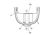
FIG. 1 is a diagram showing an appearance of a blood sugar
具体的には、図1Aに血糖値測定装置1の表側の構成を示し、図1Bにその裏側の構成を示す。筐体2の表側のパネル3上には、測定結果等を表示するための液晶画面4が設けられている。また、筐体2の端部には、血糖値測定装置1で使用される測定用の試験片、(後述する図5に示す)を差し込む試験片挿入溝10(本発明に係る着脱部に相当する)が設けられている。この試験片には、ユーザから採取された血液中のグルコースと反応し、電気的信号を出力するセンサーが設けられており、ユーザが血糖値測定の際にこのセンサーに自己の血液を点着させて、血糖値測定装置1による測定を行うこととなる。当該センサーとしては、たとえば、酸化還元酵素としてグルコースオキシターゼ(GOD)を用い、過酸化水素電極を信号出力用の電極としたセンサーが採用できる。なお、試験片そのものの構成については、従来技術によるものであって本発明の中核ではないため、本明細書でのその詳細な説明は省略する。
Specifically, FIG. 1A shows the front side configuration of the blood glucose
また、図1Bに示すように、筐体2の裏側のパネル3の側面に、血糖値測定装置1を装置するための操作ボタン7と、血糖値測定装置1と外部の装置、たとえば外部に配置されたコンピュータ等とを通信可能に接続する通信ポート8が設けられている。操作ボタン7は、ユーザによる押下操作、スライド操作、押下状態保持操作等の様々な操作の組み合わ
せにより、血糖値測定装置1で行われる全ての処理のための操作を可能とするものであり、本発明に係る操作部に相当する。
Further, as shown in FIG. 1B, on the side surface of the
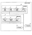
さらに、血糖値測定装置1の内部は、そこで行われる様々な処理を制御するための制御部が設けられている。血糖値測定装置1における主な制御部としては、図2においてイメージ化されているように、測定制御部20、管理制御部30、表示制御部40、外部通信部50が設けられており、これらの各制御部は、血糖値測定装置1内で形成され不図示のCPU、メモリ、ハードディスク等を含むコンピュータ上で実行されるコンピュータプログラムにより実現されるものである。また、上述した液晶画面4、操作ボタン7、通信ポート8も、図2に示す各制御部に適宜接続されており、これによりユーザへの測定結果の表示、ユーザからの操作指示の測定装置への伝達、血糖値測定装置1内で蓄積されたデータの外部への通信等に関するプログラム処理が実行される。以下、本発明に係る血糖値測定装置1の制御部の構成を説明する。
Further, the blood glucose
上述したように、血糖値測定装置1の制御部は、主に血糖値の測定に関する測定制御を行う測定制御部20、測定結果に関する管理制御を行う管理制御部30、測定結果の表示制御を行う表示制御部40、測定装置外との通信制御を行う外部通信部50で形成されているが、これ以外の制御部を含む構成となっていてもかまわない。詳細には、測定制御部20は、試験片確認部21、血糖値測定部22、測定結果記録部23、低血糖アラーム部24を有している。試験片確認部21は、上述した血糖値測定のための試験片が血糖値測定装置1側にセットされて測定可能な状態になっているかについて確認を行う機能部であり、血糖値測定部22は、確認された試験片からの出力信号に基づいてユーザの血糖値を測定する機能部である。また、測定結果記録部23は、血糖値測定部22によって測定された結果を、血糖値測定装置1内の記録装置(メモリ)にデータ保存、記録するための機能部である。さらに、低血糖アラーム部24は、測定された結果が、適正血糖値に関する基準範囲よりも低い場合にはユーザに対して低血糖であることをアラーム報知する機能部である。
As described above, the control unit of the blood glucose
また、管理制御部30は、状態フラグ設定部31、経過時間設定部32、パラメータ設定部33を有している。状態フラグ設定部31は、ユーザの血糖値に影響を及ぼす血糖値測定の際の体の状態に関するフラグを設定する機能であり、当該機能により、ユーザの血糖値管理を効率的なものとすることができる。なお、本実施例では、ユーザの体の状態を表すフラグとして、運動後、食前、食後に関する状態フラグが採用される。この状態フラグの設定については、ユーザが操作ボタン7を操作し、液晶画面4に表示される内容に従って行われる。具体的には、ユーザは、状態フラグとして、運動後フラグ、食前フラグ、食後フラグ、状態フラグ無しの4つからボタン操作により選択を行い、その選択に応じた状態フラグが、測定血糖値と関連付けられて血糖値測定装置1内に記録されることになる。これらの状態フラグは、ユーザの血糖値に強い関連性を有する体の状態に関するフラグであるから、このように測定された血糖値に状態フラグを関連付けることは、血糖値管理上極めて有用である。
In addition, the
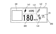
なお、これらの状態フラグの液晶画面4での表示は、表示部制御部40によって行われる。この表示制御部40は、測定制御部20による血糖値の測定結果や管理制御部30により設定された状態フラグ等を、血糖値測定装置1の液晶画面に表示するための制御部である。図3に、表示制御部40によって行われる液晶画面4上の表示の一例を示す。この表示画面例では、説明のためにアイコンや数値を一同にまとめて表示している。液晶画面4の左側には、矩形状の表示領域であって、測定結果をグラフ表示するグラフ表示領域DR1が形成され、その中央部には測定された血糖値等を表示する測定数値表示領域DR2が形成され、この測定数値表示領域DR2の周囲に、様々な意味を持つアイコンおよび所定の経過時間を表示するアイコン表示領域DR3が形成されている。このアイコン表示領
域DR3に表示されるアイコンには、低血糖アラーム用のアイコン「HYPO」、上述した状態フラグとしての運動後フラグ用アイコンIc1、食前フラグ用アイコンIc2、食後フラグ用の第一アイコンIc3、第二アイコンIc4が含まれる。さらに、アイコン表示領域DR3において、食後フラグ用の第一および第二アイコンに隣接して、食後経過時間Etが表示される。なお、表示制御部40による表示制御自体は、本発明の中核を為すものではないため、本明細書ではその詳細な説明は割愛する。
Note that the display
また状態フラグ設定部31によって設定された状態フラグが、食後フラグである場合には、本実施例に係る血糖値測定装置1では、食事で摂った食事量に関する情報もユーザは設定できる。具体的には、ユーザの主観において、満腹量の食事を摂ったときを100%としたとき、50%、80%、100%の三種類の中から一つを食事量として、ユーザは選択的できる。なお、本実施例に係る血糖値測定装置1では、この食後フラグの選択は、図3のアイコン表示領域DR3において食後フラグ用の第一アイコンIc3の表示で表され、食事量に関する表示は、食後フラグ用の第二アイコンIc4の表示とともに、当該アイコン内に表示されるバー(棒)の数を変更して行われる。たとえば、食事量が100%の場合はバーの数は三本であり(図3に示す状態)、80%、50%の場合はそれぞれバーの数は、二本、一本とされる。このように食事量に関するデータを食後フラグと関連付けることで、ユーザは、どのような量の食事を摂ったときの血糖値が測定されたのかを知ることができ、食事量と血糖値の関連を理解するとともに食事量の調整等、血糖値に関する健康管理を行いやすくなる。
When the state flag set by the state
次に、経過時間設定部32は、状態フラグ設定部31で食後の状態フラグが設定されたときの、食事終了時点からの経過時間を設定する機能部である。経過時間設定部32は、測定に先んじて、食事終了時点からの経過時間を自動的にカウントする経過時間カウンターを設定し、当該カウンターによりカウントされた経過時間を、その時点での測定結果の血糖値に関連付けする。なお、この経過時間は、図3のアイコン表示領域DR3において食後経過時間Etとして表示される。これにより、ユーザは、上記食事量に加えて、食事終了からどの程度の時間が経過したときの測定血糖値であるかを認識することができるため、さらに血糖値に関する健康管理を行いやすくなる。また、パラメータ設定部33は、血糖値測定装置1で使用される様々な制御用のパラメータを設定する機能部である。当該パラメータとしては、血糖値測定装置1内で用いられる日時や後述する試験片の容器開封日等がある。このような管理制御部30が有する機能部によって、ユーザは自己の血糖値に関する測定結果の管理を効率的に行うことが可能となる。
Next, the elapsed
また、外部通信部50は、特に測定制御部20によって測定された結果や、管理制御部30によって管理された状態フラグ等の情報を、血糖値測定装置1外に送信する制御部である。本発明に係る血糖値測定装置1においては、外部通信部50による通信制御は中核を為すものではないため、本明細書では外部通信部50によって外部通信機能が発揮されることを記載するに留め、その詳細については割愛する。
The
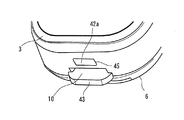
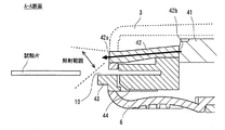
ここで、血糖値測定装置1に血糖値測定のための試験片が挿入される試験片挿入溝10近傍の構成について、図4〜図6に基づいて説明する。図4は、試験片挿入溝10近傍の血糖値測定装置1の外観の拡大図であり、図5は、血糖値測定装置1において表側のパネル3を外した状態における、該装置の上面図であり、図6は、図5におけるA−Aの断面図である(パネル3については点線で表示される)。血糖値測定装置1には、液晶画面4の背面にバックライト41が設けられている。このバックライト41はプレート形状を有し、血糖値測定装置1における血糖値測定のための電源から電力供給を受け、発光する。バックライト41は、血糖値測定装置1の長手方向の試験片挿入溝10と反対側の端部側に光源を有するエッジライト方式のものであり、本発明に係る光源部に相当する。
Here, the configuration in the vicinity of the test
ここで、血糖値測定装置1の筐体2の長手方向の側面に設けられている試験片挿入溝10の上側(液晶画面4が配置される装置表側方向)には、照明開口部45が設けられている。この照明開口部45には、導光部材42の一端42aが露出するように、該導光部材42が血糖値測定装置1内に設けられる。導光部材42は、光が入出可能な端部42a、42bを有する細長い形状を有しており、一端から入射された光を残りの一端から出射することが可能な部材である。そして、導光部材42の側部(端部以外の、長手方向に延在する部分)は、内部に入射された光がその側部から漏れ出しにくいように表面処理が為されているのが好ましい。このように形成される導光部材42は、その一端42bが、バックライト41から発せられる光が入射可能となるように、図5、図6に示すようにバックライト41に隣接して配置される。一方で、残りの一端42aが、照明開口部45で血糖値測定装置1の外部に露出するように配置される。すなわち、導光部材42は、図1Aに示すように表側のパネル3の中央部に配置される液晶画面4のバックライト41と、筐体2の側方に配置される照明開口部45とをつなぐように、血糖値測定装置1内に配置されることになる。
Here, an
なお、血糖値測定装置1においては、図6に示すように、導光部材42が若干傾斜しているように、すなわち図6において一端42bが一端42aより若干高い位置となるように配置されている。これにより、導光部材42内を導かれる光の方向が画定される。本実施例の場合は、この傾斜により、一端42aからの光は、図6におけるやや下方、すなわち試験片が存在する側に照射されることになる。このように、導光部材42の傾斜を調整することで、一端42aからの光の照射範囲をある程度調整することが可能である。
In the blood glucose
また、試験片挿入溝10は、その下側に、装置の外部に若干突出した突出部を有するガイド部材43が配置されており、ユーザは、このガイド部材43の突出部を利用して、試験片を試験片挿入溝10内に容易に滑る込ませることができる。なお、試験片挿入溝10内に挿入された試験片は、溝の奥に設けられた接続部44と電気的に接続された状態となることで、上述した試験片確認部21による試験片の挿入確認や、試験片での測定結果の装置本体への伝達、すなわち血糖値測定部22による血糖値測定が可能となる。
Further, the test
このように構成される血糖値測定装置1では、液晶画面4の光源であるバックライト41の光が、導光部材42を伝って、照明開口部45から、装置外部へ照射されることになる。照明開口部45の下側にはガイド部材43が位置していることから、この照明により試験片挿入溝10の入口部分の近傍が照らされることになり、この結果、血糖測定装置1への試験片の装着が容易に受け付けられることになる。特に、夜間等の薄暗い室内で血糖値を測定しようとするときは、この導光部材42を介したバックライト41の光を利用した照明方法は、極めて有用である。また、本発明に係る血糖値測定装置1では、試験片挿入のための専用の照明装置をその内部に設けているのではなく、導光部材42を介して、あくまでも液晶画面4のバックライトの光を有効に活用している構成となっている。そのため、測定装置の構成を簡略化できるとともに、照明に要する消費電流を実質的に不要とすることから測定装置の駆動電源の確保の観点からも好ましい。特に、携帯型の血糖値測定装置1においては、駆動電源の確保とユーザの操作性向上とが両立されるため、実用上、好ましい技術であることは理解されたい。なお、上記実施例では、バックライト41と導光部材42とが別々に構成され、互いに隣接して配置されているが、この構成に代えて、バックライト41と導光部材42とを連続した一枚の板状に形成してもよい。
In the blood sugar
ここで、バックライト41による発光は、ユーザの操作ボタン7の操作に従って行われる。具体的には、操作ボタン7を押下、スライド等することで、バックライト41を点灯させることができる。その結果、バックライト41からの発光は導光部材42を伝って照明開口部45から照射されることになる。すなわち、この操作ボタン7は、図2に基づいて説明した各制御を行うためにユーザの指示を伝えるボタンであり、また上記照明開口部
45からの光の照射を行うためのボタンでもある。
Here, the light emission by the
また、上述の実施例では、試験片の装着時における照明開口部45からの照明について言及しているが、装着された試験片を取り外す際においても操作ボタン7を操作することで、当該照明を行ってもよい。さらに、試験片へのユーザの血液の点着は、試験片の装着の前に行ってもよく、試験片を装着した後に行ってもよい。後者の場合には、試験片挿入溝10に試験片が装着された状態において、ユーザが操作ボタン7を操作してバックライト41を発光させて、照明開口部45から光を照射させることで、試験片における血液の点着箇所を照らすことができる。その結果、ユーザの血液点着作業も容易に行うことが可能となる。さらに別法として、試験片の装着時の照明の有無にかかわらず、試験片が試験片購入溝10に装着されると同時に、もしくは装着後から所定時間が経過したあるタイミングに、自動的にバックライト41を発光させてもよい。
Further, in the above-described embodiment, the illumination from the
ここで、バックライト41は、消費電力抑制の観点から常時点灯していることは好ましくない。たとえば、ユーザが操作ボタン7に対して何らかの操作を行ってから所定時間の間だけバックライト41が点灯するように制御することで、当該バックライト21による消費電力を抑制するようにしてもよい。なお、ユーザのセンサー脱着操作を効果的に支援するためには、照明開口部45における光度が1μCd/m2〜10000Cd/m2であることが好ま
しく、1mCd/m2〜2000Cd/m2であることがより好ましく、1Cd/m2〜100Cd/m2であることがより一層好ましい。
Here, it is not preferable that the
上記実施例では、液晶画面4の光源であるバックライト41からの光を、導光部材42を利用して、試験片挿入のための光源としたものであるが、血糖値測定装置1においてバックライト41以外の光源がある場合、その光源から発せられる光を導光部材によって照明開口部45に導く構成としても、当該構成は、本発明の範疇に属するものである。
In the above embodiment, the light from the
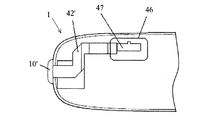
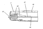
次に、本実施例の変形例に係る血糖値測定装置1を示す。図7および図8は、本変形例に係る測定装置1の要部を示す断面図である。図7は、血糖値測定装置1に係る水平断面(横断面)を模式的に示す図であり、図8は、同測定装置1に係る鉛直断面(縦断面)を模式的に示す図である。本変形例における血糖値測定装置1は、この血糖測定装置1を操作するための操作部46、操作部46をライトアップするための光源47、および光源47の光を試験片挿入溝10´に導くための導光部材42´を有する。図7には、血糖測定装置1における操作部46、光源47および導光部材42´の平面的な配置関係を示している。また、図8は、図7の直交断面を示している。
Next, a blood sugar
各図に示すように、操作部46は、血糖測定装置1の筐体の表面を構成するパネル3´に設けられており、操作部46を照射するための光源47は、血糖測定装置1内の基盤49上であって、かつ操作部46の下方に配置されている。図示のとおり、光源47と試験片挿入溝10´の間には、光源47の光が試験片挿入溝10´に導かれるように導光部材42´が形成されている。この例では、操作部46は、光源47の発光により明るく浮かび上がる素材で形成されており、光源47の発光により、操作部46がライトアップされるとともに、光源47の光が導光部材42´により試験片挿入溝10´まで導かれる。また、更に別の変形例としては、上述した通信ポート8を照射するための光源を有する血糖測定装置1において、この光源の光を試験片挿入溝に導くための導光部材を設ける態様を採用することも可能である。これらの各変形例を含め、試験片挿入用に設けられた光源ではない光源からの光を導光部材によって導く構成である限りにおいては、本発明の範疇に属する構成と言える。さらに、導光部材によって光源から導かれた光を、操作ボタン7や通信ポート8の近傍位置に照射すべく、導光部材の露出される端部を適宜配置してもよい。これにより、ユーザの操作ボタン7の操作や通信ポート8へのアクセスを支援することができる。
As shown in each figure, the
1・・・・血糖値測定装置
2・・・・筐体
4・・・・液晶画面
7・・・・操作ボタン
10・・・・試験片挿入溝
20・・・・測定制御部
30・・・・管理制御部
40・・・・表示制御部
41・・・・バックライト
42・・・・導光部材
43・・・・ガイド部材
45・・・・照明開口部
DESCRIPTION OF
Claims (10)
装置本体と、
前記装置本体に設けられ、前記生体情報を測定するセンサーが着脱される着脱部と、
前記装置本体内において前記着脱部から離間した位置で、該着脱部以外の前記生体情報測定装置の構成のための光源として機能する光源部と、
前記光源部によって照射された光を、前記センサーが着脱される前記着脱部近傍の所定位置まで導く導光部材と、
を備える、生体情報測定装置。 A biological information measuring device that measures biological information of a user,
The device body;
An attachment / detachment unit provided in the apparatus main body, to which a sensor for measuring the biological information is attached / detached;
A light source unit that functions as a light source for the configuration of the biological information measuring device other than the detachable unit at a position separated from the detachable unit in the apparatus main body;
A light guide member that guides the light emitted by the light source unit to a predetermined position in the vicinity of the attachment / detachment unit to / from which the sensor is attached / detached;
A biological information measuring device comprising:
前記光源部は、前記ディスプレイの光源として機能するバックライトである、請求項1に記載の生体情報測定装置。 A display for displaying biological information measured via the sensor;
The biological information measuring device according to claim 1, wherein the light source unit is a backlight that functions as a light source of the display.
前記導光部材は、前記バックライトの光を前記所定位置に導く長さを有する、
請求項2に記載の生体情報測定装置。 The attachment / detachment portion is provided on a side surface of the apparatus main body,
The light guide member has a length for guiding the light of the backlight to the predetermined position.
The biological information measuring device according to claim 2.
前記操作部がユーザに操作されると、前記光源部による発光が行われ、前記導光部材によって前記所定位置へその光が導かれる、
請求項1から請求項3の何れか一項に記載の生体情報測定装置。 An operation unit for a user to operate the biological information measuring device;
When the operation unit is operated by the user, the light source unit emits light, and the light is guided to the predetermined position by the light guide member.
The biological information measuring device according to any one of claims 1 to 3.
請求項4に記載の生体情報測定装置。 When the sensor is attached to the detachable part, the light source part emits light, and the light is guided to the predetermined position by the light guide member.
The biological information measuring device according to claim 4.
前記着脱部には、ユーザの血液が点着されてその血糖値に応じた電流出力を出す血糖値測定用センサーが着脱される、
請求項1から請求項5の何れか一項に記載の生体情報測定装置。 The biological information measuring device is a device for measuring a user's blood sugar level,
A blood glucose level measurement sensor for outputting a current output corresponding to the blood glucose level by spotting the user's blood is attached to and detached from the attachment / detachment unit.
The biological information measuring device according to any one of claims 1 to 5.
請求項1から請求項6の何れか一項に記載の生体情報測定装置。 The biological information measuring device is a device that can be carried by a user.
The biological information measuring device according to any one of claims 1 to 6.
前記装置本体内において前記着脱部から離間した位置で、該着脱部以外の前記生体情報測定装置の構成のための光源として機能する光源部を発光させる第一ステップと、
前記第一ステップで、前記光源部によって照射された光を、前記センサーが着脱される前記着脱部近傍の所定位置と該光源部との間に設けられた導光部材を介して、該所定位置まで導く第二ステップと、
を含む、生体情報測定装置における照明方法。 In the biological information measuring device for measuring a user's biological information, the apparatus main body and a sensor for measuring the user's biological information have an attachment / detachment unit attached to and detached from the device main body from outside the device. An illumination method for performing illumination,
A first step of causing a light source unit functioning as a light source for the configuration of the biological information measuring device other than the attaching / detaching unit to emit light at a position apart from the attaching / detaching unit in the device main body;
In the first step, the light emitted from the light source unit is transmitted to the predetermined position via a light guide member provided between the light source unit and a predetermined position in the vicinity of the attachment / detachment unit where the sensor is attached / detached. The second step leading to
A lighting method in a biological information measuring device.
前記装置本体内において前記着脱部から離間した位置で、該着脱部以外の前記生体情報
測定装置の構成のための光源として機能する光源部を発光させる発光ステップと、
前記発光ステップでの前記光源部が、前記着脱部近傍の所定位置と該光源部との間に設けられた導光部材に対して発光している状態で、前記着脱部への前記センサーの装着を受け付ける装着ステップと、
を含む、生体情報測定方法。 In a biological information measuring device having a device main body and a sensor for measuring a user's biological information, and a detachable part attached to and detached from the device main body from the outside of the device, a measuring method for measuring the user's biological information,
A light emission step of causing a light source unit functioning as a light source for the configuration of the biological information measuring device other than the attachment / detachment unit to emit light at a position separated from the attachment / detachment unit in the device body;
Mounting of the sensor to the attachment / detachment unit in a state where the light source unit in the light emission step emits light to a light guide member provided between a predetermined position near the attachment / detachment unit and the light source unit A mounting step for receiving,
A biological information measuring method including:
前記着脱部への前記センサーの装着を受け付ける装着ステップと、
前記装着ステップにおいて前記センサーの装着が受け付けられると、前記装置本体内において前記着脱部から離間した位置で該着脱部以外の前記生体情報測定装置の構成のための光源として機能する光源部を、前記着脱部近傍の所定位置と該光源部との間に設けられた導光部材に対して発光させる発光ステップと、
を含む、生体情報測定方法。 In a biological information measuring device having a device main body and a sensor for measuring a user's biological information, and a detachable part attached to and detached from the device main body from the outside of the device, a measuring method for measuring the user's biological information,
A mounting step for receiving mounting of the sensor on the detachable portion;
When mounting of the sensor is accepted in the mounting step, a light source unit that functions as a light source for the configuration of the biological information measuring device other than the mounting / dismounting unit at a position separated from the mounting / detaching unit in the device main body, A light emitting step of emitting light to a light guide member provided between a predetermined position near the attachment / detachment portion and the light source portion;
A biological information measuring method including:
Priority Applications (5)
| Application Number | Priority Date | Filing Date | Title |
|---|---|---|---|
| JP2011057911A JP2011237408A (en) | 2010-04-14 | 2011-03-16 | Biological information measuring device, lighting method in the same and biological information measuring method |
| US13/086,260 US20110257533A1 (en) | 2010-04-14 | 2011-04-13 | Biological information measurement device, illumination method in a biological information measurement device, and biological information measurement method |
| KR1020110034206A KR20110115092A (en) | 2010-04-14 | 2011-04-13 | Biometric information measuring device, illumination method in biometric information measuring device, and biometric information measuring method |
| EP11162484.7A EP2377465B1 (en) | 2010-04-14 | 2011-04-14 | Biological information measurement device, illumination method in a biological information measurement device, and biological information measurement method |
| CN2011100934775A CN102279155A (en) | 2010-04-14 | 2011-04-14 | Biological information measurement device, illumination method in a biological information measurement device, and biological information measurement method |
Applications Claiming Priority (3)
| Application Number | Priority Date | Filing Date | Title |
|---|---|---|---|
| JP2010093571 | 2010-04-14 | ||
| JP2010093571 | 2010-04-14 | ||
| JP2011057911A JP2011237408A (en) | 2010-04-14 | 2011-03-16 | Biological information measuring device, lighting method in the same and biological information measuring method |
Publications (1)
| Publication Number | Publication Date |
|---|---|
| JP2011237408A true JP2011237408A (en) | 2011-11-24 |
Family
ID=44176330
Family Applications (1)
| Application Number | Title | Priority Date | Filing Date |
|---|---|---|---|
| JP2011057911A Pending JP2011237408A (en) | 2010-04-14 | 2011-03-16 | Biological information measuring device, lighting method in the same and biological information measuring method |
Country Status (5)
| Country | Link |
|---|---|
| US (1) | US20110257533A1 (en) |
| EP (1) | EP2377465B1 (en) |
| JP (1) | JP2011237408A (en) |
| KR (1) | KR20110115092A (en) |
| CN (1) | CN102279155A (en) |
Cited By (3)
| Publication number | Priority date | Publication date | Assignee | Title |
|---|---|---|---|---|
| JP2012098080A (en) * | 2010-10-29 | 2012-05-24 | Arkray Inc | Analyzer |
| WO2014181753A1 (en) * | 2013-05-10 | 2014-11-13 | ニプロ株式会社 | Measuring device |
| JP2016515710A (en) * | 2013-04-17 | 2016-05-30 | ライフスキャン・スコットランド・リミテッド | Handheld test instrument with display illumination adjustment circuit block |
Families Citing this family (17)
| Publication number | Priority date | Publication date | Assignee | Title |
|---|---|---|---|---|
| US8465977B2 (en) | 2008-07-22 | 2013-06-18 | Roche Diagnostics Operations, Inc. | Method and apparatus for lighted test strip |
| WO2013099128A1 (en) * | 2011-12-27 | 2013-07-04 | パナソニック株式会社 | Biological sample measuring device |
| US9897565B1 (en) | 2012-09-11 | 2018-02-20 | Aseko, Inc. | System and method for optimizing insulin dosages for diabetic subjects |
| US9171343B1 (en) | 2012-09-11 | 2015-10-27 | Aseko, Inc. | Means and method for improved glycemic control for diabetic patients |
| US8894262B2 (en) | 2013-03-11 | 2014-11-25 | Roche Diagnostic Operations, Inc. | Blood glucose test strip illumination device and method |
| USD724224S1 (en) * | 2013-09-04 | 2015-03-10 | Arkray, Inc. | Test meter |
| USD724223S1 (en) * | 2013-09-04 | 2015-03-10 | Arkray, Inc. | Test meter |
| USD752758S1 (en) * | 2013-09-11 | 2016-03-29 | Samsung Electronics Co., Ltd. | Blood glucose meter |
| US9486580B2 (en) | 2014-01-31 | 2016-11-08 | Aseko, Inc. | Insulin management |
| US9898585B2 (en) | 2014-01-31 | 2018-02-20 | Aseko, Inc. | Method and system for insulin management |
| US10036709B2 (en) | 2014-05-20 | 2018-07-31 | Roche Diabetes Care, Inc. | BG meter illuminated test strip |
| JP1519885S (en) * | 2014-06-10 | 2015-03-23 | ||
| EP3933845A3 (en) | 2014-10-27 | 2022-06-22 | Aseko, Inc. | Subcutaneous outpatient management |
| US11081226B2 (en) | 2014-10-27 | 2021-08-03 | Aseko, Inc. | Method and controller for administering recommended insulin dosages to a patient |
| JP6858751B2 (en) | 2015-08-20 | 2021-04-14 | アセコー インコーポレイテッド | Diabetes Management Therapy Advisor |
| US10955334B2 (en) * | 2017-12-14 | 2021-03-23 | Essenlix Corporation | Optical transmission sample holder and analysis, particularly for hemoglobin |
| TWI707662B (en) * | 2019-09-12 | 2020-10-21 | 華廣生技股份有限公司 | Physiological sensing apparatus for reading a strip |
Citations (5)
| Publication number | Priority date | Publication date | Assignee | Title |
|---|---|---|---|---|
| JPH11235196A (en) * | 1998-02-20 | 1999-08-31 | Kdk Corp | Biosensor system |
| JP2003512866A (en) * | 1999-07-28 | 2003-04-08 | アボット・ラボラトリーズ | Luminescent glucose monitor |
| JP2009205118A (en) * | 2008-01-29 | 2009-09-10 | Victor Co Of Japan Ltd | Rotary joint |
| JP2009226217A (en) * | 2008-03-21 | 2009-10-08 | Lifescan Scotland Ltd | Specimen inspection method and system |
| JP2009260133A (en) * | 2008-04-18 | 2009-11-05 | Hitachi Computer Peripherals Co Ltd | Laser annealing method, and laser annealing device |
Family Cites Families (4)
| Publication number | Priority date | Publication date | Assignee | Title |
|---|---|---|---|---|
| US108551A (en) * | 1870-10-25 | Improvement in horse hay-foxks | ||
| US7444173B2 (en) * | 2000-12-29 | 2008-10-28 | Vertu Ltd. | Mobile telephone |
| JP4432818B2 (en) | 2005-04-01 | 2010-03-17 | セイコーエプソン株式会社 | Image display device, image display method, and image display program |
| JP4631028B2 (en) | 2005-04-04 | 2011-02-16 | 独立行政法人産業技術総合研究所 | Biosensor detector |
-
2011
- 2011-03-16 JP JP2011057911A patent/JP2011237408A/en active Pending
- 2011-04-13 KR KR1020110034206A patent/KR20110115092A/en not_active Ceased
- 2011-04-13 US US13/086,260 patent/US20110257533A1/en not_active Abandoned
- 2011-04-14 EP EP11162484.7A patent/EP2377465B1/en active Active
- 2011-04-14 CN CN2011100934775A patent/CN102279155A/en active Pending
Patent Citations (5)
| Publication number | Priority date | Publication date | Assignee | Title |
|---|---|---|---|---|
| JPH11235196A (en) * | 1998-02-20 | 1999-08-31 | Kdk Corp | Biosensor system |
| JP2003512866A (en) * | 1999-07-28 | 2003-04-08 | アボット・ラボラトリーズ | Luminescent glucose monitor |
| JP2009205118A (en) * | 2008-01-29 | 2009-09-10 | Victor Co Of Japan Ltd | Rotary joint |
| JP2009226217A (en) * | 2008-03-21 | 2009-10-08 | Lifescan Scotland Ltd | Specimen inspection method and system |
| JP2009260133A (en) * | 2008-04-18 | 2009-11-05 | Hitachi Computer Peripherals Co Ltd | Laser annealing method, and laser annealing device |
Cited By (4)
| Publication number | Priority date | Publication date | Assignee | Title |
|---|---|---|---|---|
| JP2012098080A (en) * | 2010-10-29 | 2012-05-24 | Arkray Inc | Analyzer |
| JP2016515710A (en) * | 2013-04-17 | 2016-05-30 | ライフスキャン・スコットランド・リミテッド | Handheld test instrument with display illumination adjustment circuit block |
| WO2014181753A1 (en) * | 2013-05-10 | 2014-11-13 | ニプロ株式会社 | Measuring device |
| JPWO2014181753A1 (en) * | 2013-05-10 | 2017-02-23 | ニプロ株式会社 | measuring device |
Also Published As
| Publication number | Publication date |
|---|---|
| EP2377465A1 (en) | 2011-10-19 |
| EP2377465B1 (en) | 2014-08-27 |
| KR20110115092A (en) | 2011-10-20 |
| US20110257533A1 (en) | 2011-10-20 |
| CN102279155A (en) | 2011-12-14 |
Similar Documents
| Publication | Publication Date | Title |
|---|---|---|
| JP2011237408A (en) | Biological information measuring device, lighting method in the same and biological information measuring method | |
| CN104203097B (en) | Battery status detection and storage method and system in medical monitoring | |
| EP2310849B1 (en) | Method and apparatus for lighted test strip | |
| ES2752743T3 (en) | Blood glucose monitoring device | |
| JP5336314B2 (en) | Blood glucose meter | |
| US20110034786A1 (en) | Portable handheld medical diagnostic devices | |
| EP1997431A1 (en) | Biosensor and apparatus for measuring concentration of components | |
| CN100394186C (en) | Two-way blood glucose monitor | |
| WO2010149389A2 (en) | Episodic blood glucose monitoring system with an interactive graphical user interface and methods thereof | |
| WO2012127870A1 (en) | Living organism information measurement device | |
| JP2015112209A (en) | Electronic device, method and program | |
| JPWO2013046911A1 (en) | Analyte monitor system | |
| JP6455425B2 (en) | measuring device | |
| JPWO2013038826A1 (en) | Notification system | |
| EP2848197A1 (en) | Portable diagnostic test apparatus | |
| JP4352107B2 (en) | Liquid sample measuring device with lens | |
| JP4085137B2 (en) | Biosensor system | |
| JP2000131263A5 (en) | ||
| WO2006132953A2 (en) | Solar-powered integrated-diagnostic instrument | |
| CN220019344U (en) | Blood fat detector | |
| CN214668538U (en) | Dry-type fluorescence immunoassay device | |
| CN211669081U (en) | Novel quick diabetes detection device | |
| JP7440054B2 (en) | Biological information collection device | |
| JP3188252B2 (en) | Portable equipment and lighting body used for the same | |
| JP2013076598A (en) | Medical apparatus, error information processing system and error information processing program |
Legal Events
| Date | Code | Title | Description |
|---|---|---|---|
| A621 | Written request for application examination |
Free format text: JAPANESE INTERMEDIATE CODE: A621 Effective date: 20140207 |
|
| A977 | Report on retrieval |
Free format text: JAPANESE INTERMEDIATE CODE: A971007 Effective date: 20140926 |
|
| A131 | Notification of reasons for refusal |
Free format text: JAPANESE INTERMEDIATE CODE: A131 Effective date: 20140930 |
|
| A521 | Request for written amendment filed |
Free format text: JAPANESE INTERMEDIATE CODE: A523 Effective date: 20141201 |
|
| A02 | Decision of refusal |
Free format text: JAPANESE INTERMEDIATE CODE: A02 Effective date: 20150428 |