JP2011237293A - Radioactive material storage method - Google Patents
Radioactive material storage method Download PDFInfo
- Publication number
- JP2011237293A JP2011237293A JP2010109209A JP2010109209A JP2011237293A JP 2011237293 A JP2011237293 A JP 2011237293A JP 2010109209 A JP2010109209 A JP 2010109209A JP 2010109209 A JP2010109209 A JP 2010109209A JP 2011237293 A JP2011237293 A JP 2011237293A
- Authority
- JP
- Japan
- Prior art keywords
- trunk body
- water
- cask
- trunk
- radioactive substance
- Prior art date
- Legal status (The legal status is an assumption and is not a legal conclusion. Google has not performed a legal analysis and makes no representation as to the accuracy of the status listed.)
- Pending
Links
Images

Classifications
-
- Y—GENERAL TAGGING OF NEW TECHNOLOGICAL DEVELOPMENTS; GENERAL TAGGING OF CROSS-SECTIONAL TECHNOLOGIES SPANNING OVER SEVERAL SECTIONS OF THE IPC; TECHNICAL SUBJECTS COVERED BY FORMER USPC CROSS-REFERENCE ART COLLECTIONS [XRACs] AND DIGESTS
- Y02—TECHNOLOGIES OR APPLICATIONS FOR MITIGATION OR ADAPTATION AGAINST CLIMATE CHANGE
- Y02E—REDUCTION OF GREENHOUSE GAS [GHG] EMISSIONS, RELATED TO ENERGY GENERATION, TRANSMISSION OR DISTRIBUTION
- Y02E30/00—Energy generation of nuclear origin
- Y02E30/30—Nuclear fission reactors
Landscapes
- Packages (AREA)
Abstract
Description
本発明は、使用済燃料などの放射性物質を収納容器に収納する放射性物質収納方法に関する。 The present invention relates to a radioactive substance storage method for storing a radioactive substance such as spent fuel in a storage container.
核燃料サイクルの終期にあって、原子炉にて燃焼させた使用済燃料(放射性物質)は、高放射能物質を含み、その崩壊熱が発生するために熱的に冷却する必要があることから、原子力発電所の冷却ピットで所定期間にわたって冷却される。その後、使用済燃料は、キャスク(収納容器)に収納され、輸送船、トラックの搬送方法により中間貯蔵施設、再処理工場などに搬送して貯蔵または処理される。なお、使用済燃料は、貯蔵にあたり、棒状のものが支持格子により複数支持された燃料集合体として構成されている(以下、使用済燃料を使用済燃料集合体という)。 At the end of the nuclear fuel cycle, spent fuel (radioactive material) burned in the nuclear reactor contains high-activity materials and must be cooled thermally in order to generate decay heat. It is cooled for a predetermined period in the cooling pit of a nuclear power plant. Thereafter, the spent fuel is stored in a cask (storage container), and is transported to an intermediate storage facility, a reprocessing factory, or the like by a transport ship or truck transport method for storage or processing. Note that the spent fuel is configured as a fuel assembly in which a plurality of rod-shaped ones are supported by a support grid during storage (hereinafter, the spent fuel is referred to as a spent fuel assembly).
キャスクは、一般的に、上部が開口して円筒形状をなす胴本体と、この胴本体の外周部に設けられた中性子遮蔽体であるレジンと、このレジンの外周部に設けられた外筒と、胴本体の内部に配置されて使用済燃料集合体を収容するバスケットと、胴本体の上部に固定される一次蓋及び二次蓋とから構成されている。 The cask generally has a cylindrical main body with an open top, a resin that is a neutron shield provided on the outer periphery of the main body, and an outer cylinder provided on the outer periphery of the resin. The basket is disposed inside the trunk body and accommodates spent fuel assemblies, and the primary lid and the secondary lid are fixed to the upper portion of the trunk body.
使用済燃料集合体をキャスクに収納するには、蓋が取り外されたキャスクの胴本体をこの燃料貯蔵プールに沈め、水中でこの胴本体内のバスケットに使用済燃料集合体を収容する作業を行う。そして、胴本体内に所定本数の使用済燃料集合体が収容されると、胴本体が水中に沈められたまま、胴本体の上部に一次蓋を固定することで上部開口を閉止する。続いて、一次蓋が固定された胴本体をプールから吊上げて取り出した後、除染ピット内で、一次蓋に形成されたベント・ドレン孔を通して内部の水を排出すると共に、真空ポンプを用いて残留した水を吸引除去し、キャビティ内にヘリウムガスを充填して密閉する。そして、胴本体の上部に二次蓋を固定することで上部開口を完全に閉止する。その後、使用済燃料集合体が収容されたキャスクは、中間貯蔵施設で適正な年数、つまり、所定の温度以下に冷却されるまで保管される(例えば、非特許文献1参照)。 In order to store the spent fuel assembly in the cask, the trunk body of the cask with the lid removed is submerged in the fuel storage pool and the spent fuel assembly is accommodated in a basket inside the trunk body underwater. . When a predetermined number of spent fuel assemblies are accommodated in the trunk body, the upper opening is closed by fixing the primary lid to the upper part of the trunk body while the trunk body is submerged in water. Subsequently, after the trunk body with the primary lid fixed is lifted from the pool and taken out, inside the decontamination pit, the internal water is discharged through a vent / drain hole formed in the primary lid, and a vacuum pump is used. The remaining water is removed by suction, and the cavity is filled with helium gas and sealed. And an upper opening is completely closed by fixing a secondary lid to the upper part of a trunk body. Thereafter, the cask containing the spent fuel assembly is stored in the intermediate storage facility until it is cooled to an appropriate number of years, that is, a predetermined temperature or less (see, for example, Non-Patent Document 1).
近年では、保管する使用済燃料集合体が増加傾向にあり、より多くの使用済燃料集合体をキャスクに収納する要望がある。ところが、使用済燃料集合体をプール内においてキャスクに収納し、胴本体をプールから吊上げる際、胴本体内に水が充填されていることから、当該作業時が最も重い状態であって、クレーンの揚重設備容量を超えることが考えられる。このため、クレーン揚重設備容量に応じた使用済燃料集合体の収納数とする必要があり、収納効率が低下する場合などがあった。この制限を緩和し収納効率を向上させるには、より高い揚重設備容量のクレーンを新設しなければならず、設備コストが嵩むことになる。 In recent years, the spent fuel assemblies to be stored tend to increase, and there is a demand for storing more spent fuel assemblies in the cask. However, when the spent fuel assembly is stored in the cask in the pool and the trunk body is lifted from the pool, the trunk body is filled with water. It is conceivable to exceed the lifting equipment capacity. For this reason, it is necessary to set the number of stored spent fuel assemblies according to the crane lifting equipment capacity, and the storage efficiency may be reduced. In order to relax this restriction and improve the storage efficiency, it is necessary to newly install a crane having a higher lifting equipment capacity, which increases the equipment cost.
本発明は上述した課題を解決するものであり、収納容器の重量を軽量化することのできる放射性物質収納方法を提供することを目的とする。 This invention solves the subject mentioned above, and it aims at providing the radioactive substance storage method which can reduce the weight of a storage container.
上述の目的を達成するために、本発明の放射性物質収納方法は、蓋部が取り外された収納容器の胴本体を水中に沈め、前記胴本体内に放射性物質を収容する工程と、次に、前記胴本体を水中に沈めたままで前記胴本体の上部開口に前記蓋部を取り付ける工程と、次に、前記胴本体を水中に沈めたままで前記胴本体内の水を排出する工程と、次に、前記収納容器を水中から取り出す工程と、を含むことを特徴とする。 In order to achieve the above-described object, the radioactive substance storage method of the present invention includes a step of submerging the trunk body of the storage container from which the lid is removed, and storing the radioactive substance in the trunk body, and Attaching the lid to the upper opening of the trunk body while the trunk body is submerged in water; next, discharging the water in the trunk body while submerging the trunk body in water; and And a step of taking out the storage container from the water.
この放射性物質収納方法によれば、胴本体を水中に沈めたままで胴本体内の水を排出するため、水中から取り出すときの収納容器の重量を軽量化することができる。この結果、収納容器を水中から取り出すときの揚重設備に係る荷重が軽減され、ハンドリング性を向上することができる。また、収納容器の重量が軽量化された分、揚重設備の容量の制限内で、より多くの放射性物質を収納容器に収納することができる。 According to this radioactive substance storage method, since the water in the trunk body is discharged while the trunk body is submerged in water, the weight of the storage container when taken out from the water can be reduced. As a result, the load related to the lifting equipment when the storage container is taken out from the water is reduced, and handling properties can be improved. Further, since the weight of the storage container is reduced, more radioactive material can be stored in the storage container within the limit of the capacity of the lifting equipment.
また、本発明の放射性物質収納方法では、前記胴本体内の水を排出する工程において、前記胴本体内に不活性ガスを導入することを特徴とする。 The radioactive substance storage method of the present invention is characterized in that an inert gas is introduced into the trunk body in the step of discharging the water in the trunk body.
この放射性物質収納方法によれば、不活性ガスの導入により、水を排出した後の温度上昇を防ぐことができる。この結果、温度上昇により金属ガスケットが腐食する事態を防ぐことができる。しかも、放射性物質の保護などにより収納容器内部の構造が複雑化して狭隘部分が多くなることにより、水はけが悪くなって後の真空乾燥に要する時間が延びる傾向にあるが、胴本体を水中に沈めたままで胴本体内の水を排出して、胴本体内に不活性ガスを導入することで、水はけを良好にし、真空乾燥に要する時間が延びる事態を抑制することができる。 According to this radioactive substance storage method, an increase in temperature after discharging water can be prevented by introducing an inert gas. As a result, it is possible to prevent the metal gasket from corroding due to temperature rise. In addition, the structure inside the storage container is complicated due to protection of radioactive substances and the number of narrow parts increases, so that drainage becomes worse and the time required for subsequent vacuum drying tends to increase, but the trunk body is submerged in water. By draining the water in the trunk body as it is and introducing an inert gas into the trunk body, it is possible to improve drainage and to prevent the time required for vacuum drying from being prolonged.
また、本発明の放射性物質収納方法では、前記収納容器を水中から取り出す工程中に、前記胴本体内に不活性ガスを導入することを特徴とする。 In the radioactive substance storage method of the present invention, an inert gas is introduced into the trunk body during the step of taking out the storage container from the water.
この放射性物質収納方法によれば、不活性ガスの導入により、水を排出した後の温度上昇を防ぐことができる。この結果、温度上昇により金属ガスケットが腐食する事態を防ぐことができる。しかも、放射性物質の保護などにより収納容器内部の構造が複雑化して狭隘部分が多くなることにより、水はけが悪くなって後の真空乾燥に要する時間が延びる傾向にあるが、胴本体を水中に沈めたままで胴本体内の水を排出して、胴本体内に不活性ガスを導入することで、水はけを良好にし、真空乾燥に要する時間が延びる事態を抑制することができる。 According to this radioactive substance storage method, an increase in temperature after discharging water can be prevented by introducing an inert gas. As a result, it is possible to prevent the metal gasket from corroding due to temperature rise. In addition, the structure inside the storage container is complicated due to protection of radioactive substances and the number of narrow parts increases, so that drainage becomes worse and the time required for subsequent vacuum drying tends to increase, but the trunk body is submerged in water. By draining the water in the trunk body as it is and introducing an inert gas into the trunk body, it is possible to improve drainage and to prevent the time required for vacuum drying from being prolonged.
また、本発明の放射性物質収納方法では、前記胴本体内の水を排出する工程において、止具により前記蓋部を前記胴本体に押さえ付けることを特徴とする。 Moreover, in the radioactive substance storage method of this invention, the said cover part is pressed down on the said trunk | drum main body with a stopper in the process of discharging the water in the said trunk | drum main body, It is characterized by the above-mentioned.
この放射性物質収納方法によれば、水の排出中に胴本体内の内圧により蓋部が浮く事態を防止し、胴本体内への水の侵入を防ぐことができる。 According to this radioactive substance storage method, it is possible to prevent the lid from floating due to the internal pressure in the trunk body during the discharge of water, and to prevent water from entering the trunk body.
本発明によれば、収納容器の重量を軽量化することができる。 According to the present invention, the weight of the storage container can be reduced.
以下に、本発明に係る実施の形態を図面に基づいて詳細に説明する。なお、この実施の形態によりこの発明が限定されるものではない。また、下記実施の形態における構成要素には、当業者が置換可能かつ容易なもの、あるいは実質的に同一のものが含まれる。 Embodiments according to the present invention will be described below in detail with reference to the drawings. Note that the present invention is not limited to the embodiments. In addition, constituent elements in the following embodiments include those that can be easily replaced by those skilled in the art or those that are substantially the same.
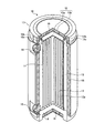
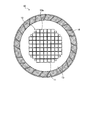
図1は、本実施の形態の放射性物質収納方法に適用される収納容器(キャスク)の一例を示す一部断面概略図であり、図2は、図1に示す収納容器の横断面概略図である。 FIG. 1 is a partial cross-sectional schematic view showing an example of a storage container (cask) applied to the radioactive substance storage method of the present embodiment, and FIG. 2 is a cross-sectional schematic view of the storage container shown in FIG. is there.
図1および図2に示すように、放射性物質を収納する収納容器としてのキャスク10は、略円筒形状に形成されている。キャスク10は、キャビティ11と、バスケット12と、容器本体としての胴本体13と、底部14と、蓋部15と、中性子遮蔽体16と、補助遮蔽体17とを備える。なお、補助遮蔽体17は、収納するリサイクル燃料の仕様によって、装着が必要な場合に補助的に用いられるものである。
As shown in FIGS. 1 and 2, a
キャビティ11は、キャスク10の内部に形成されている。キャビティ11は、胴本体13と底部14と蓋部15によって囲まれる空間である。バスケット12は、キャスク10の内部に設けられる。バスケット12は、後述する使用済燃料集合体20を収納するセル12aを有する。バスケット12は、例えば、中性子吸収性能をもつ材料の粉末を添加したアルミニウム複合材によって構成される。キャビティ11は、その内面が、バスケット12の外周形状に合わせて形成されている。なお、キャビティ11を単純形状の円筒形として、キャビティ11とバスケット12との間のセルとして使えない隙間に伝熱性能に優れたスペーサを配置したものとしてもよい。
The
胴本体13は、略円筒形状に形成されている。胴本体13は、一方の端部に底部14が溶接により結合される。また、胴本体13は、他方の開口端に蓋部15が設けられる。また、胴本体13は、その外側にトラニオン18が固定されている。トラニオン18は、キャスク10をクレーンなどの揚重設備で吊るための吊具として機能する。胴本体13は、周囲に中性子遮蔽体16が封入されている。中性子遮蔽体16は、水素を多く含有する高分子材料であって中性子遮蔽機能を実現するものである。中性子遮蔽体16は、中性子吸収剤としてほう素またはほう素化合物を含むレジンが代表的である。これにより、胴本体13は、中性子遮蔽機能が高められる。また、底部14は、内部に中性子遮蔽体16が封入され、中性子遮蔽機能が高められている。
The
蓋部15は、胴本体13の底部14とは反対側の開口端を閉塞する。蓋部15は、一次蓋15aと二次蓋15bとを含んで構成される。一次蓋15aは、γ線を遮蔽する炭素鋼やステンレス鋼を材料として円盤形状に形成される。二次蓋15bも、一次蓋15aと同様に、γ線を遮蔽する炭素鋼やステンレス鋼を材料として円盤形状に形成される。また、二次蓋15bは、内部に中性子遮蔽体16が封入され、中性子遮蔽機能が高められている。
The
一次蓋15aおよび二次蓋15bは、炭素鋼やステンレス鋼を材料とするボルト19a,19bにより胴本体13に取付けられる。この時、図には明示しないが、一次蓋15aと胴本体13との間には金属ガスケットが設けられる。また、図には明示しないが、二次蓋15bと胴本体13との間にも、金属ガスケットが設けられる。この金属ガスケットは、一次蓋15aと胴本体13との間の密封性を確保する。また、金属ガスケットは、二次蓋15bと胴本体13との間の密封性を確保する。
The
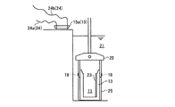
図3〜図9は、本実施の形態に係る放射性物質収納方法を示す工程図である。この図3〜図9を参照し、上述したキャスク(収納容器)10に放射性物質としての使用済燃料集合体20を収納する収納方法について説明する。使用済燃料集合体20は、使用済燃料棒が支持格子により複数支持されたものである。なお、キャスク10に収納される放射性物質は、使用済燃料集合体20に限らず、未使用燃料や放射性廃棄物を含む。
3 to 9 are process diagrams showing the radioactive substance storage method according to the present embodiment. A storage method for storing the spent
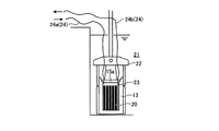
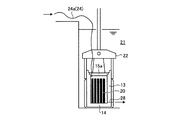
図3に示すように、蓋部15が取り外された状態のキャスク10の胴本体13を燃料貯蔵プール21(またはキャスクローディングピット)の水底に沈める。これにより、胴本体13の内部のキャビティ11は、燃料貯蔵プール21の水で満たされた状態となる。胴本体13は、トラニオン18に掛けられたクレーン22により吊り下げられて燃料貯蔵プール21内に運ばれる。なお、本実施の形態のキャスク10は、胴本体13の内部のキャビティ11に、底部14から上部開口に向けて上下に延在する排水管23が設けられている。一方、取り外された蓋部15の一次蓋15aは、胴本体13の内部のキャビティ11に通じる管24が設けられている。管24は、一次蓋15aに設けられた図示しないベントポートおよびドレンポートに対して着脱自在に設けられている。本実施の形態において、管24は、給気ライン24aと排水ライン24bとで構成されている。給気ライン24aは、一次蓋15aを胴本体13に取り付けた状態で、胴本体13の内部のキャビティ11上部域に通じる。また、排水ライン24bは、一次蓋15aを胴本体13に取り付けた状態で、排水管23に連通する。なお、胴本体13は、燃料貯蔵プール21の水により胴本体13が汚れる事態を防ぐため、その外周が防染バッグ25で覆われている。
As shown in FIG. 3, the
次に、図4に示すように、胴本体13を燃料貯蔵プール21に沈めたままで、胴本体13の内部のキャビティ11に設けられたバスケット12の各セル12aに、使用済燃料集合体20を収容する。使用済燃料集合体20は、燃料取扱工具26により吊り下げられてセル12aに装荷される。
Next, as shown in FIG. 4, the spent
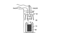
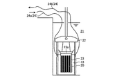
次に、図5および図6に示すように、胴本体13を燃料貯蔵プール21に沈めたままで、胴本体13の上部開口に一次蓋15aを取り付ける。一次蓋15aは、クレーン22により吊り下げられて胴本体13に対して設置される。ここで、数本のボルト19aを止具とし、一次蓋15aを胴本体13に押さえ付ける。なお、一次蓋15aを胴本体13に押さえ付ける止具は、ボルト19aに限らず、例えば、一次蓋15aを設置したクレーン22をそのまま用いてもよい。
Next, as shown in FIGS. 5 and 6, the
次に、図6に示すように、胴本体13を燃料貯蔵プール21に沈めたままで、胴本体13の内部のキャビティ11の水を排出する。具体的には、給気ライン24aにより不活性ガス(例えば、ヘリウム、アルゴン、または窒素)を給気することで、キャビティ11内の水を排水管23および排水ライン24bにより排出する。給気した気体が排水ライン24bから排気されることでキャビティ11内の水の大部分が排出されたことを確認できる。なお、全ての水が排出された後も、不活性ガスを給気し続ける。
Next, as shown in FIG. 6, the water in the
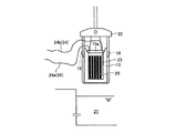
次に、図7に示すように、一次蓋15aが取り付けられた胴本体13(キャスク10)を、燃料貯蔵プール21の外部に取り出す。キャスク10は、トラニオン18に掛けられたクレーン22により吊り上げられて燃料貯蔵プール21外に運ばれる。燃料貯蔵プール21の外部に取り出されたキャスク10は、図8に示すように、除染場27に載置される。なお、キャスク10を燃料貯蔵プール21の外部に取り出す本工程中に、不活性ガスを給気し続ける。
Next, as shown in FIG. 7, the trunk body 13 (cask 10) to which the
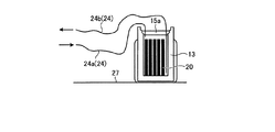
次に、図8に示すように、一次蓋15aをボルト19aにより密閉し、図示しない真空ポンプを用いてキャビティ11に残留した水を吸引除去し(真空乾燥)、キャビティ11にヘリウムガスを充填する。
Next, as shown in FIG. 8, the
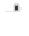
次に、図9に示すように、給気ライン24aおよび排水ライン24bを取り外し、胴本体13の上部に二次蓋15bを固定することで上部開口を完全に閉止する。
Next, as shown in FIG. 9, the
なお、図10の排水構造の他の例を示す概略図に示すように、排水管23および排水ライン24bを用いなくてもよい。この場合、胴本体13のキャビティ11の水を燃料貯蔵プール21に排出する排出口28を、胴本体13の底部14側に配置する。排出口28には、燃料貯蔵プール21の水がキャビティ11内に逆流する事態を防ぐために逆止弁を設ける。
In addition, as shown to the schematic which shows the other example of the drainage structure of FIG. 10, the
また、胴本体13の内部のキャビティ11の水を排出する工程では、図示しない真空ポンプを用いて排水ライン24bからキャビティ11の水を吸引しつつ、給気ライン24aから不活性ガスを供給してもよい。
Further, in the step of discharging the water in the
また、図11の排水構造の他の例を示す概略図に示すように、上述した給気ライン24aおよび排水ライン24bは、胴本体13に着脱自在に取り付けられる構成であってもよい。
Moreover, as shown in the schematic diagram which shows the other example of the drainage structure of FIG. 11, the structure by which the
このように、本実施の形態の放射性物質収納方法は、胴本体13を水中に沈めたままで胴本体13内のキャビティ11の水を排出する。このため、水中から取り出すときのキャスク10の重量を軽量化することが可能になる。この結果、キャスク10を水中から取り出すときのクレーン22に係る荷重が軽減され、ハンドリング性を向上できる。また、キャスク10の重量が軽量化された分、クレーン22の揚重設備容量の制限内で、より多くの使用済燃料集合体20をキャスク10に収納できる。
Thus, the radioactive substance storage method of the present embodiment discharges water from the
また、本実施の形態の放射性物質収納方法では、胴本体13内のキャビティ11の水を排出する工程において、胴本体13内のキャビティ11に不活性ガスを導入する。このため、水を排出した後の温度上昇を防ぐことが可能になる。この結果、温度上昇により金属ガスケットが腐食する事態を防ぐことが可能になる。しかも、使用済燃料集合体20の保護などによりバスケット12の構造が複雑化して狭隘部分が多くなることにより、水はけが悪くなって後の真空乾燥に要する時間が延びる傾向にあるが、胴本体13を水中に沈めたままで胴本体13内のキャビティ11の水を排出して、胴本体13内のキャビティ11に不活性ガスを導入することで、水はけを良好にし、真空乾燥に要する時間が延びる事態を抑制することが可能になる。
In the radioactive substance storage method of the present embodiment, an inert gas is introduced into the
また、本実施の形態の放射性物質収納方法では、キャスク10を水中から取り出す工程中に、胴本体13内のキャビティ11に不活性ガスを導入する。このため、水を排出した後の温度上昇を防ぐことが可能になる。この結果、温度上昇により金属ガスケットが腐食する事態を防ぐことが可能になる。しかも、使用済燃料集合体20の保護などによりバスケット12の構造が複雑化して狭隘部分が多くなることにより、水はけが悪くなって後の真空乾燥に要する時間が延びる傾向にあるが、胴本体13を水中に沈めたままで胴本体13内のキャビティ11の水を排出して、胴本体13内のキャビティ11に不活性ガスを導入することで、水はけを良好にし、真空乾燥に要する時間が延びる事態を抑制することが可能になる。
Moreover, in the radioactive substance storage method of this Embodiment, an inert gas is introduce | transduced into the
また、本実施の形態の放射性物質収納方法では、胴本体13内のキャビティ11の水を排出する工程において、止具(ボルト19aまたはクレーン22)により一次蓋15aを胴本体13に押さえ付ける。このため、水の排出中にキャビティ11の内圧により一次蓋15aが浮く事態を防止し、キャビティ11への水の侵入を防ぐことが可能になる。
Moreover, in the radioactive substance storage method of this Embodiment, the primary lid |
以上のように、本発明に係る放射性物質収納方法は、収納容器の重量を軽量化することに適している。 As described above, the radioactive substance storage method according to the present invention is suitable for reducing the weight of the storage container.
10 キャスク
11 キャビティ
12 バスケット
12a セル
13 胴本体
14 底部
15 蓋部
15a 一次蓋
15b 二次蓋
16 中性子遮蔽体
17 補助遮蔽体
18 トラニオン
19a,19b ボルト
20 使用済燃料集合体
21 燃料貯蔵プール
22 クレーン
23 排水管
24 管
24a 給気ライン
24b 排水ライン
25 防染バッグ
26 燃料取扱工具
27 除染場
28 排出口
DESCRIPTION OF
Claims (4)
次に、前記胴本体を水中に沈めたままで前記胴本体の上部開口に前記蓋部を取り付ける工程と、
次に、前記胴本体を水中に沈めたままで前記胴本体内の水を排出する工程と、
次に、前記収納容器を水中から取り出す工程と、
を含むことを特徴とする放射性物質収納方法。 Submerging the trunk body of the storage container from which the lid is removed, and storing a radioactive substance in the trunk body;
Next, attaching the lid to the upper opening of the trunk body while submerging the trunk body in water;
Next, discharging the water in the trunk body while the trunk body is submerged in water;
Next, a step of taking out the storage container from the water,
The radioactive substance storage method characterized by including.
Priority Applications (1)
| Application Number | Priority Date | Filing Date | Title |
|---|---|---|---|
| JP2010109209A JP2011237293A (en) | 2010-05-11 | 2010-05-11 | Radioactive material storage method |
Applications Claiming Priority (1)
| Application Number | Priority Date | Filing Date | Title |
|---|---|---|---|
| JP2010109209A JP2011237293A (en) | 2010-05-11 | 2010-05-11 | Radioactive material storage method |
Publications (1)
| Publication Number | Publication Date |
|---|---|
| JP2011237293A true JP2011237293A (en) | 2011-11-24 |
Family
ID=45325439
Family Applications (1)
| Application Number | Title | Priority Date | Filing Date |
|---|---|---|---|
| JP2010109209A Pending JP2011237293A (en) | 2010-05-11 | 2010-05-11 | Radioactive material storage method |
Country Status (1)
| Country | Link |
|---|---|
| JP (1) | JP2011237293A (en) |
Cited By (3)
| Publication number | Priority date | Publication date | Assignee | Title |
|---|---|---|---|---|
| CN105304151A (en) * | 2015-09-17 | 2016-02-03 | 中广核工程有限公司 | Fuel storage tank for dry type storage of spent fuel of nuclear power plant |
| JP2021046999A (en) * | 2019-09-16 | 2021-03-25 | ゲーエヌエス・ゲゼルシャフト・フューア・ヌクレアール−サービス・ミト・ベシュレンクテル・ハフツング | Method of drying shipping container and/or storage container |
| JP2021124327A (en) * | 2020-02-03 | 2021-08-30 | 東芝プラントシステム株式会社 | Drying system and drying method |
Citations (4)
| Publication number | Priority date | Publication date | Assignee | Title |
|---|---|---|---|---|
| JPS61155995A (en) * | 1984-12-24 | 1986-07-15 | ウエスチングハウス エレクトリック コーポレーション | Spent nuclear fuel storage cask |
| JPH07218686A (en) * | 1994-02-04 | 1995-08-18 | Ishikawajima Harima Heavy Ind Co Ltd | Method and device for loading spent fuel into canister |
| JPH0980196A (en) * | 1995-09-11 | 1997-03-28 | Ishikawajima Harima Heavy Ind Co Ltd | Spent fuel storage method and container |
| JPH1114792A (en) * | 1997-06-24 | 1999-01-22 | Ishikawajima Harima Heavy Ind Co Ltd | Storage method for spent nuclear fuel and storage container thereof |
-
2010
- 2010-05-11 JP JP2010109209A patent/JP2011237293A/en active Pending
Patent Citations (4)
| Publication number | Priority date | Publication date | Assignee | Title |
|---|---|---|---|---|
| JPS61155995A (en) * | 1984-12-24 | 1986-07-15 | ウエスチングハウス エレクトリック コーポレーション | Spent nuclear fuel storage cask |
| JPH07218686A (en) * | 1994-02-04 | 1995-08-18 | Ishikawajima Harima Heavy Ind Co Ltd | Method and device for loading spent fuel into canister |
| JPH0980196A (en) * | 1995-09-11 | 1997-03-28 | Ishikawajima Harima Heavy Ind Co Ltd | Spent fuel storage method and container |
| JPH1114792A (en) * | 1997-06-24 | 1999-01-22 | Ishikawajima Harima Heavy Ind Co Ltd | Storage method for spent nuclear fuel and storage container thereof |
Cited By (4)
| Publication number | Priority date | Publication date | Assignee | Title |
|---|---|---|---|---|
| CN105304151A (en) * | 2015-09-17 | 2016-02-03 | 中广核工程有限公司 | Fuel storage tank for dry type storage of spent fuel of nuclear power plant |
| JP2021046999A (en) * | 2019-09-16 | 2021-03-25 | ゲーエヌエス・ゲゼルシャフト・フューア・ヌクレアール−サービス・ミト・ベシュレンクテル・ハフツング | Method of drying shipping container and/or storage container |
| JP7591889B2 (en) | 2019-09-16 | 2024-11-29 | ゲーエヌエス・ゲゼルシャフト・フューア・ヌクレアール-サービス・ミト・ベシュレンクテル・ハフツング | Method for drying transport and/or storage containers |
| JP2021124327A (en) * | 2020-02-03 | 2021-08-30 | 東芝プラントシステム株式会社 | Drying system and drying method |
Similar Documents
| Publication | Publication Date | Title |
|---|---|---|
| CN112313756B (en) | Multi-component cask for storing and transporting spent nuclear fuel | |
| US11728058B2 (en) | Systems and methods for transferring spent nuclear fuel from wet storage to dry storage | |
| US11373773B2 (en) | Method for making containment cask for drum containing radioactive hazardous waste | |
| US6587536B1 (en) | Method and apparatus for maximizing radiation shielding during cask transfer procedures | |
| KR100666885B1 (en) | How to load radioactive materials and sealed containers | |
| WO2018108073A1 (en) | Nuclear power plant spent fuel storage and transportation metal tank | |
| CN110506310A (en) | The container of storage and transport spent fuel | |
| JP2002243888A (en) | Sealing method for radioactive material and cooling device | |
| JP2011237293A (en) | Radioactive material storage method | |
| JP5808303B2 (en) | Radioactive material transport storage container | |
| JP5634924B2 (en) | Method for tailoring radioactive material transport storage container and lid auxiliary shield for tailoring work | |
| WO2011148742A1 (en) | Radioactive substance storage container | |
| CN206040222U (en) | Spent Fuel Storage Containers | |
| CN116348966A (en) | Heavy Water Reactor Spent Fuel Transport Basket | |
| RU2067326C1 (en) | Assembly to reload spent nuclear fuel | |
| JP2004156997A (en) | Spent nuclear fuel container | |
| KR20150007631A (en) | radiation active waste storage apparatus | |
| CN112820436A (en) | Storage sealing device and transportation maintenance method | |
| CN210245087U (en) | A multi-purpose spent fuel assembly container with a multi-layer lid structure | |
| CN110444307A (en) | A multi-purpose spent fuel assembly container with a multi-layer cover structure | |
| JP2000098082A (en) | Spent fuel storage cask and method of using the same | |
| JP2003270382A (en) | Radioactive material containment vessel and radioactive material containment method | |
| CN218676492U (en) | Retired reactor hanging basket cutting piece waste bag shielding device | |
| CN106205757A (en) | Spentnuclear fuel storage-transport vessel | |
| US20250357015A1 (en) | Simplified economic ventilated metal storage system (sevmss) |
Legal Events
| Date | Code | Title | Description |
|---|---|---|---|
| A621 | Written request for application examination |
Free format text: JAPANESE INTERMEDIATE CODE: A621 Effective date: 20130204 |
|
| A977 | Report on retrieval |
Free format text: JAPANESE INTERMEDIATE CODE: A971007 Effective date: 20140129 |
|
| A131 | Notification of reasons for refusal |
Free format text: JAPANESE INTERMEDIATE CODE: A131 Effective date: 20140318 |
|
| A521 | Written amendment |
Free format text: JAPANESE INTERMEDIATE CODE: A523 Effective date: 20140501 |
|
| A02 | Decision of refusal |
Free format text: JAPANESE INTERMEDIATE CODE: A02 Effective date: 20141111 |