JP2011237170A - Pulse tube type refrigerator and rotary valve for use therein - Google Patents
Pulse tube type refrigerator and rotary valve for use therein Download PDFInfo
- Publication number
- JP2011237170A JP2011237170A JP2011138747A JP2011138747A JP2011237170A JP 2011237170 A JP2011237170 A JP 2011237170A JP 2011138747 A JP2011138747 A JP 2011138747A JP 2011138747 A JP2011138747 A JP 2011138747A JP 2011237170 A JP2011237170 A JP 2011237170A
- Authority
- JP
- Japan
- Prior art keywords
- pulse tube
- valve
- port
- gas flowing
- valve seat
- Prior art date
- Legal status (The legal status is an assumption and is not a legal conclusion. Google has not performed a legal analysis and makes no representation as to the accuracy of the status listed.)
- Granted
Links
Images


Classifications
-
- F—MECHANICAL ENGINEERING; LIGHTING; HEATING; WEAPONS; BLASTING
- F25—REFRIGERATION OR COOLING; COMBINED HEATING AND REFRIGERATION SYSTEMS; HEAT PUMP SYSTEMS; MANUFACTURE OR STORAGE OF ICE; LIQUEFACTION SOLIDIFICATION OF GASES
- F25B—REFRIGERATION MACHINES, PLANTS OR SYSTEMS; COMBINED HEATING AND REFRIGERATION SYSTEMS; HEAT PUMP SYSTEMS
- F25B9/00—Compression machines, plants or systems, in which the refrigerant is air or other gas of low boiling point
- F25B9/14—Compression machines, plants or systems, in which the refrigerant is air or other gas of low boiling point characterised by the cycle used, e.g. Stirling cycle
- F25B9/145—Compression machines, plants or systems, in which the refrigerant is air or other gas of low boiling point characterised by the cycle used, e.g. Stirling cycle pulse-tube cycle
-
- F—MECHANICAL ENGINEERING; LIGHTING; HEATING; WEAPONS; BLASTING
- F25—REFRIGERATION OR COOLING; COMBINED HEATING AND REFRIGERATION SYSTEMS; HEAT PUMP SYSTEMS; MANUFACTURE OR STORAGE OF ICE; LIQUEFACTION SOLIDIFICATION OF GASES
- F25B—REFRIGERATION MACHINES, PLANTS OR SYSTEMS; COMBINED HEATING AND REFRIGERATION SYSTEMS; HEAT PUMP SYSTEMS
- F25B9/00—Compression machines, plants or systems, in which the refrigerant is air or other gas of low boiling point
- F25B9/10—Compression machines, plants or systems, in which the refrigerant is air or other gas of low boiling point with several cooling stages
-
- F—MECHANICAL ENGINEERING; LIGHTING; HEATING; WEAPONS; BLASTING
- F25—REFRIGERATION OR COOLING; COMBINED HEATING AND REFRIGERATION SYSTEMS; HEAT PUMP SYSTEMS; MANUFACTURE OR STORAGE OF ICE; LIQUEFACTION SOLIDIFICATION OF GASES
- F25B—REFRIGERATION MACHINES, PLANTS OR SYSTEMS; COMBINED HEATING AND REFRIGERATION SYSTEMS; HEAT PUMP SYSTEMS
- F25B2309/00—Gas cycle refrigeration machines
- F25B2309/006—Gas cycle refrigeration machines using a distributing valve of the rotary type
-
- F—MECHANICAL ENGINEERING; LIGHTING; HEATING; WEAPONS; BLASTING
- F25—REFRIGERATION OR COOLING; COMBINED HEATING AND REFRIGERATION SYSTEMS; HEAT PUMP SYSTEMS; MANUFACTURE OR STORAGE OF ICE; LIQUEFACTION SOLIDIFICATION OF GASES
- F25B—REFRIGERATION MACHINES, PLANTS OR SYSTEMS; COMBINED HEATING AND REFRIGERATION SYSTEMS; HEAT PUMP SYSTEMS
- F25B2309/00—Gas cycle refrigeration machines
- F25B2309/14—Compression machines, plants or systems characterised by the cycle used
- F25B2309/1408—Pulse-tube cycles with pulse tube having U-turn or L-turn type geometrical arrangements
-
- F—MECHANICAL ENGINEERING; LIGHTING; HEATING; WEAPONS; BLASTING
- F25—REFRIGERATION OR COOLING; COMBINED HEATING AND REFRIGERATION SYSTEMS; HEAT PUMP SYSTEMS; MANUFACTURE OR STORAGE OF ICE; LIQUEFACTION SOLIDIFICATION OF GASES
- F25B—REFRIGERATION MACHINES, PLANTS OR SYSTEMS; COMBINED HEATING AND REFRIGERATION SYSTEMS; HEAT PUMP SYSTEMS
- F25B2309/00—Gas cycle refrigeration machines
- F25B2309/14—Compression machines, plants or systems characterised by the cycle used
- F25B2309/1411—Pulse-tube cycles characterised by control details, e.g. tuning, phase shifting or general control
-
- F—MECHANICAL ENGINEERING; LIGHTING; HEATING; WEAPONS; BLASTING
- F25—REFRIGERATION OR COOLING; COMBINED HEATING AND REFRIGERATION SYSTEMS; HEAT PUMP SYSTEMS; MANUFACTURE OR STORAGE OF ICE; LIQUEFACTION SOLIDIFICATION OF GASES
- F25B—REFRIGERATION MACHINES, PLANTS OR SYSTEMS; COMBINED HEATING AND REFRIGERATION SYSTEMS; HEAT PUMP SYSTEMS
- F25B2309/00—Gas cycle refrigeration machines
- F25B2309/14—Compression machines, plants or systems characterised by the cycle used
- F25B2309/1418—Pulse-tube cycles with valves in gas supply and return lines
- F25B2309/14181—Pulse-tube cycles with valves in gas supply and return lines the valves being of the rotary type
-
- F—MECHANICAL ENGINEERING; LIGHTING; HEATING; WEAPONS; BLASTING
- F25—REFRIGERATION OR COOLING; COMBINED HEATING AND REFRIGERATION SYSTEMS; HEAT PUMP SYSTEMS; MANUFACTURE OR STORAGE OF ICE; LIQUEFACTION SOLIDIFICATION OF GASES
- F25B—REFRIGERATION MACHINES, PLANTS OR SYSTEMS; COMBINED HEATING AND REFRIGERATION SYSTEMS; HEAT PUMP SYSTEMS
- F25B2309/00—Gas cycle refrigeration machines
- F25B2309/14—Compression machines, plants or systems characterised by the cycle used
- F25B2309/1424—Pulse tubes with basic schematic including an orifice and a reservoir
-
- Y—GENERAL TAGGING OF NEW TECHNOLOGICAL DEVELOPMENTS; GENERAL TAGGING OF CROSS-SECTIONAL TECHNOLOGIES SPANNING OVER SEVERAL SECTIONS OF THE IPC; TECHNICAL SUBJECTS COVERED BY FORMER USPC CROSS-REFERENCE ART COLLECTIONS [XRACs] AND DIGESTS
- Y10—TECHNICAL SUBJECTS COVERED BY FORMER USPC
- Y10T—TECHNICAL SUBJECTS COVERED BY FORMER US CLASSIFICATION
- Y10T137/00—Fluid handling
- Y10T137/8593—Systems
- Y10T137/86493—Multi-way valve unit
- Y10T137/86863—Rotary valve unit
Landscapes
- Engineering & Computer Science (AREA)
- Physics & Mathematics (AREA)
- Mechanical Engineering (AREA)
- Thermal Sciences (AREA)
- General Engineering & Computer Science (AREA)
- Multiple-Way Valves (AREA)
Abstract
Description
本発明は、ギフォード・マクマホン(GM)タイプのパルスチューブ冷凍機に関する。かかる極低温冷凍機のコールドヘッドは、バルブ機構を含み、当該バルブ機構は、通常的には、ロータリバルブディスクとバルブシートからなる。離散的なポートが存在し、異なるポートの周期的な配置により、コンプレッサにより供給された作動流体が、蓄冷器及びコールドヘッドの作動容積に対して出入りすることが可能となる。 The present invention relates to a Gifford McMahon (GM) type pulse tube refrigerator. The cold head of such a cryogenic refrigerator includes a valve mechanism, and the valve mechanism usually includes a rotary valve disk and a valve seat. There are discrete ports and the periodic arrangement of the different ports allows the working fluid supplied by the compressor to enter and exit the working volume of the regenerator and cold head.
GMタイプの冷凍機は、略一定の高圧でガスを供給し、略一定の低圧でガスを受け入れるコンプレッサを用いる。ガスは、バルブ機構によりコンプレッサに対して低速で作動する往復動エクスパンダに供給され、往復動エクスパンダは、エクスパンダ内及び外にガスを交互に導く。特許文献1には、バルブのフェースの両端で緊密なシールを維持するために高低の圧力差を用いるマルチポート型ロータリディスクが開示される。この種のバルブは、異なるタイプのGM冷凍機において広く用いられてきた(例えば、特許文献2、3参照)。この種のバルブは、複数のバルブのためのポート又はより大きなポートを収容するために径が増加するにつれて、トルクの増大を必要とするという欠点を有している。
The GM type refrigerator uses a compressor that supplies gas at a substantially constant high pressure and receives gas at a substantially constant low pressure. The gas is supplied to a reciprocating expander that operates at a low speed with respect to the compressor by a valve mechanism, and the reciprocating expander alternately guides the gas into and out of the expander.
パルスチューブ冷凍機は、先ず、特許文献4により開示され、それは、以前のGM冷凍機のような、バルブに接続されるパルスチューブを開示する。それは、また、コンプレッサと同一の速度で脈動するようにコンプレッサに直接接続されたパルスチューブエクスパンダを開示する。これは、スターリングサイクル冷凍機と同等である。従前のパルスチューブ冷凍機は、GMタイプの冷凍機と競合するほど十分効率的でなかった。顕著な改善は、1984年に非特許文献5で報告され、更なる改善を求めて多くの関心が続けられた。1984年以降の大きな改善の記載は、非特許文献6〜9に見られる。また、改善の更なる開示が特許文献10に見出せる。 A pulse tube refrigerator is first disclosed by U.S. Patent No. 6,057,096, which discloses a pulse tube connected to a valve, such as the previous GM refrigerator. It also discloses a pulse tube expander connected directly to the compressor to pulsate at the same speed as the compressor. This is equivalent to a Stirling cycle refrigerator. Previous pulse tube refrigerators were not efficient enough to compete with GM type refrigerators. A significant improvement was reported in Non-Patent Document 5 in 1984, and much interest continued for further improvements. A description of significant improvements since 1984 can be found in Non-Patent Documents 6-9. Further disclosure of the improvement can be found in US Pat.
これらのパルスチューブのすべては、パルスチューブに対してガスを周期的に流入及び流出させるためにバルブを用いるGMタイプのエクスパンダとして稼動できるが、シングル及びダブルオリフィスのパルスチューブだけしか、スターリングタイプのエクスパンダとして稼動できない。スターリングタイプのパルスチューブは、比較的高速で作動するので小型である。高速化は、低温に至ることを困難化するので、低速で稼動するGMタイプのパルスチューブは、典型的には、約20K以下での用途で使用される。4Kでの最も良い性能が、特許文献11の図9に示すようなパルスチューブにより得られることが見出されている。この設計は、特許文献11の図11に示す順序で開閉する、蓄冷器への流れを制御する2つのバルブと、パルスチューブの高温側端部への流れを制御する4つのバルブを有する。このパルスチューブの単一段のバージョンは、4つのバルブを有し、その2つは、蓄冷器用であり、2つはパルスチューブ用であり、従って、この制御は、一般的には4バルブ制御と称される。これらのバルブの機能は、一般的に、マルチポートのロータリディスクバルブの使用により実現される。 All of these pulse tubes can operate as GM type expanders that use valves to cycle gas in and out of the pulse tube, but only single and double orifice pulse tubes can be Cannot operate as an expander. A Stirling type pulse tube is small because it operates at a relatively high speed. Acceleration makes it difficult to reach low temperatures, so GM type pulse tubes operating at low speed are typically used in applications below about 20K. It has been found that the best performance at 4K can be obtained with a pulse tube as shown in FIG. This design has two valves that control the flow to the regenerator and four valves that control the flow to the high temperature side end of the pulse tube that open and close in the order shown in FIG. This single stage version of the pulse tube has four valves, two for the regenerator and two for the pulse tube, so this control is generally a four-valve control. Called. The function of these valves is generally realized by the use of a multi-port rotary disc valve.
固定のシート上にディスク回転体を有するバルブを設計するとき、シート内に、蓄冷器に接続する一以上のポートを有し、蓄冷器に対してガスを同一のポートを通って流入及び流出させるのが通常である。たいていのGM冷凍機は、2つのポートを用い、バルブディスクの回転毎に2回の冷却サイクルを有するが、特許文献12に開示されるように、3つのポートが使用されていた。GMエクスパンダに対して回転毎に1サイクルの冷却を提供する単一のポートバルブは、特許文献13に開示されている。このバルブは、従来のロータリバルブとは、コンプレッサからの高圧ガスをバルブシートに作用させてバルブシートをロータリバルブのフェース内へと押圧させる点が異なる。ベアリングは、バルブシートの軸方向力をモータシャフトに軸方向力として伝達するよりもむしろ、バルブシートの軸方向力に対してバルブディスクを保持する。高圧ガスは、中心のポート内に流れ、低圧ガスは、バルブの外周に吐出される。 When designing a valve having a disk rotating body on a fixed seat, the seat has one or more ports connected to the regenerator, and gas flows into and out of the regenerator through the same port. It is normal. Most GM refrigerators use two ports and have two cooling cycles per rotation of the valve disk, but as disclosed in US Pat. A single port valve that provides one cycle of cooling per revolution to the GM expander is disclosed in US Pat. This valve is different from the conventional rotary valve in that high-pressure gas from the compressor is applied to the valve seat to press the valve seat into the face of the rotary valve. Rather than transmitting the axial force of the valve seat as an axial force to the motor shaft, the bearing holds the valve disc against the axial force of the valve seat. The high pressure gas flows into the central port, and the low pressure gas is discharged to the outer periphery of the valve.
特許文献11の図11は、第1の段のパルスチューブPT1に対して、第2の段のパルスチューブPT2に流入及びから流出するガスに対して異なるタイミングを開示するが、これらのバルブのその他の重要な特徴、即ち各バルブのオリフィスのサイズが異なることについては開示していない。各パルスチューブに流れるガスの量を制御すること共に、同一量のガスを流入の際に高圧から低圧に戻すことが必要である。密度が異なるため、各パルスチューブに対するバルブにおけるオリフィスのサイズは異ならなければならない。 FIG. 11 of Patent Document 11 discloses different timings for the gas flowing into and out of the second-stage pulse tube PT2 with respect to the first-stage pulse tube PT1, but the other of these valves Is not disclosed, i.e., the size of each valve orifice is different. In addition to controlling the amount of gas flowing through each pulse tube, it is necessary to return the same amount of gas from high pressure to low pressure upon inflow. Due to the different densities, the size of the orifice in the valve for each pulse tube must be different.
ロータリフェースバルブにおいて、バルブシートにおける蓄冷器へのポートは、同一の径の円ないしトラック上にある。これは、高圧供給と低圧戻しが、回転するディスクにおける長穴により交互に接続されるからである。回転毎に単一の冷却サイクルを有するバルブディスクに対しては、パルスチューブへの4つのポートのそれぞれを、異なる半径位置にて、相互間で漏れが無いように十分に径方向で隙間を置いて位置させる必要がある。従って、バルブは、5つのトラックを有し、1つは、蓄冷器への流入及びからの流出のためのものであり、4つは、パルスチューブへの流入及びからの流出のためのものである。これは、バルブの直径を増大させ、結果的に、トルクを顕著に増大させる。
本発明は、パルスチューブ用のロータリフェースバルブの径と共に、それを回転させるのに必要なトルクを低減することを目的とする。 The object of the present invention is to reduce the torque required to rotate the rotary face valve for a pulse tube together with the diameter thereof.
本発明は、蓄冷器と、1段目パルスチューブと、2段目パルスチューブと、蓄冷器に流入するガスの流れを制御するロータリバルブと、を備えるパルスチューブ冷凍機であって、
ロータリバルブは、バルブシートと、バルブシートと対向接触しながら相対回転するバルブディスクと、を有し、バルブシートのバルブディスクと対向する面に、1段目パルスチューブへ流れるガスのためのポートと、1段目パルスチューブから流れるガスのためのポートと、2段目パルスチューブへ流れるガスのためのポートと、2段目パルスチューブから流れるガスのためのポートと、を配置するパルスチューブ冷凍機である。
The present invention is a pulse tube refrigerator comprising a regenerator, a first-stage pulse tube, a second-stage pulse tube, and a rotary valve that controls the flow of gas flowing into the regenerator,
The rotary valve has a valve seat and a valve disc that rotates relative to the valve seat while facing the valve seat, and a port for the gas flowing to the first-stage pulse tube on a surface of the valve seat facing the valve disc. A pulse tube refrigerator having a port for gas flowing from the first stage pulse tube, a port for gas flowing to the second stage pulse tube, and a port for gas flowing from the second stage pulse tube It is.
本発明は、また、パルスチューブ冷凍機の蓄冷器に流入するガスの流れを制御するロータリバルブであって、バルブシートと、バルブシートと対向接触しながら相対回転するバルブディスクとを有し、バルブシートのバルブディスクと対向する面に、1段目パルスチューブへ流れるガスのためのポートと、1段目パルスチューブから流れるガスのためのポートと、2段目パルスチューブへ流れるガスのためのポートと、2段目パルスチューブから流れるガスのためのポートと、を配置するロータリバルブである。 The present invention is also a rotary valve that controls the flow of gas flowing into a regenerator of a pulse tube refrigerator, and includes a valve seat and a valve disk that rotates relative to the valve seat while facing the valve seat. A port for the gas flowing to the first stage pulse tube, a port for the gas flowing from the first stage pulse tube, and a port for the gas flowing to the second stage pulse tube on the surface of the seat facing the valve disk And a port for the gas flowing from the second stage pulse tube.
本発明の一実施形態は、マルチバルブ、好ましくは4バルブ、2段パルスチューブ用に設計されたロータリフェースバルブを回転させるのに必要なトルクを低減する。これは、バルブを、1回転当たり2回の冷却サイクルを有すると共に、単一のトラック上にパルスチューブへの2つの高圧ポートを有し、別の単一のトラック上にパルスチューブからの2つの低圧ポートを有するように、設計することにより実現される。蓄冷器への流れは、2つのポートを通る一方、パルスチューブへの及びからの流れは、バルブシートにおける各1つのポートを通る。2つの高圧ポートは、低圧ポートと同様、約180度離れており、第2段のパルスチューブへのポートは、開口時間を増加させ且つ第1段のポートに対して開口を先行させるために、長穴化される。バルブディスクにおける長穴は対称であり、第1段のポートに対して所望の開口時間を提供する幅を有する。 One embodiment of the present invention reduces the torque required to rotate a multi-valve, preferably a rotary face valve designed for a four-valve, two-stage pulse tube. This means that the valve has two cooling cycles per revolution and has two high pressure ports to the pulse tube on a single track and two from the pulse tube on another single track. This is achieved by designing to have a low pressure port. The flow to the regenerator passes through two ports, while the flow to and from the pulse tube passes through each one port in the valve seat. The two high pressure ports, like the low pressure port, are about 180 degrees apart, and the port to the second stage pulse tube increases the opening time and leads the opening to the first stage port. It is made into a long hole. The elongated holes in the valve disk are symmetrical and have a width that provides the desired opening time for the first stage port.
回転毎に1の冷却サイクルを有するバルブに対してトラック数を5から3に低減し、1つは、蓄冷器への及びからの流れに対するものであり、残りは、2つのパルスチューブの高温側端部への及びからの流れに対するものである。トラック数の低減は、また、バルブの直径を低減し、それを回すのに必要なトルクを低減する。 Reduce the number of tracks from 5 to 3 for valves with one cooling cycle per revolution, one for the flow to and from the regenerator, the rest for the hot side of the two pulse tubes For flow to and from the end. The reduction in the number of tracks also reduces the diameter of the valve and the torque required to turn it.
本発明は、4バルブ式GMタイプ2段パルスチューブ冷凍機に適用可能である。 The present invention is applicable to a 4-valve GM type two-stage pulse tube refrigerator.
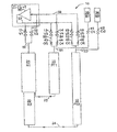
図1は、システムを通るガス流路を示す2段4バルブ式パルスチューブ冷凍機10の概略図である。図1は、特許文献11の図9に図示された基本的な2段4バルブ式パルスチューブ冷凍機における幾つかの改良点を示す。高圧ガスPhは、コンプレッサ60からガスライン57を通りバルブ11(V1),13(V3)及び15(V5)に流れる。低圧ガスPlは、コンプレッサ60に、バルブ12(V2),14(V4)と16(V6)からライン58を通り戻る。バルブV1,V2は、ライン50を通って蓄冷器21(R1)へ流入及びから流出する流れを制御する。バルブV3は、ライン53、オリフィス43(O3)及びライン51を通る第1段のパルスチューブ31(PT1)への流れを制御する。バルブV5は、ライン55、オリフィス45(O5)及びライン52を通る第2段のパルスチューブ32への流れを制御する。バルブV4は、ライン51、オリフィス44(O4)及びライン54を通るPT1からの流れを制御する。バルブV6は、ライン52、オリフィス46(O6)及びライン56を通るPT2からの流れを制御する。PT1の高温側端部に流入及びから流出するガスの一部は、ライン51、オリフィス41(O1)及びバッファー容積33(B1)を介して流れる。同様に、PT2の高温側端部に流入及びから流出するガスの一部は、ライン52、オリフィス42(O2)及びバッファー容積34(B2)を介して流れる。
FIG. 1 is a schematic diagram of a two-stage four-valve pulse tube refrigerator 10 showing gas flow paths through the system. FIG. 1 shows some improvements in the basic two-stage four-valve pulse tube refrigerator shown in FIG. The high-pressure gas Ph flows from the compressor 60 through the gas line 57 to the valves 11 (V1), 13 (V3), and 15 (V5). The low-pressure gas Pl returns to the compressor 60 from the valves 12 (V2), 14 (V4) and 16 (V6) through the line 58. The valves V1 and V2 control the flow flowing into and out of the regenerator 21 (R1) through the
R1,PT1,PT2の入口端部は、周囲温度に近い一方で、PT1,PT2の他の端部は、蓄冷器R1,蓄冷器22(R2)及び接続管23,34を流れた後のガスの低温側端部への脈動の結果、冷たくなる。パルスチューブ内に残るガスは、ガスピストンと看做すことができる。PT1及びPT2の高温側へと流れるガスは、ガスピストンの動きを制御し、冷却が低温側端部で生成されるようにする。4バルブ型2段パルスチューブの動作の更なる説明は、特許文献11に含まれる。 The inlet ends of R1, PT1, and PT2 are close to the ambient temperature, while the other ends of PT1 and PT2 are the gas after flowing through the regenerator R1, the regenerator 22 (R2), and the connecting pipes 23 and As a result of the pulsation to the low temperature side end of the plate, it becomes cold. The gas remaining in the pulse tube can be regarded as a gas piston. The gas flowing to the high temperature side of PT1 and PT2 controls the movement of the gas piston so that cooling is generated at the low temperature end. Further description of the operation of the four-valve type two-stage pulse tube is included in US Pat.
特許文献11の図9に対する図1に示す改善は、オリフィスO3,O4、O5,O6、及び、バッファー容積の2つの別の容積B1,B2への分割である。オリフィスは、好ましくは、可変であり、製造工程中に冷却を最適化するように調整されることができる。一旦、流路の最適なサイズが決定されると、それらは、バルブV3,V4,V5及びV6におけるポート内に組み込まれることができる。バッファー容積をそれぞれのパルスチューブに対する別の容積に分けることは、一のパルスチューブからガスのバッファー容積を介した他方のパルスチューブへのガスの循環の可能性を無くす。 The improvement shown in FIG. 1 with respect to FIG. 9 of US Pat. No. 6,057,836 is the division of the orifices O3, O4, O5, O6 and the buffer volume into two separate volumes B1, B2. The orifice is preferably variable and can be adjusted to optimize cooling during the manufacturing process. Once the optimum size of the flow path is determined, they can be incorporated into the ports at valves V3, V4, V5 and V6. Dividing the buffer volume into separate volumes for each pulse tube eliminates the possibility of gas circulation from one pulse tube through the gas buffer volume to the other pulse tube.
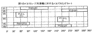
図2は、冷却を最適化するために見出された開時間を示すバルブV1〜V6に対するタイミングチャートである。重要なこととしては、バルブのそれぞれに対する時間に差異を認識することである。本発明の目的は、これらの異なるタイミングを、単一ロータリディスク型バルブの設計に組み込むことである。 FIG. 2 is a timing chart for valves V1-V6 showing the open times found to optimize cooling. The important thing is to recognize the difference in time for each of the valves. The purpose of the present invention is to incorporate these different timings into the design of a single rotary disk type valve.
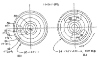
図3及び図4は、固定型のバルブシート60と、バルブシート60に適合し、長穴57における高圧Ph及び長穴58における低圧Plがバルブシート60におけるポート上を通過する際に回転毎に1サイクルの冷却を提供するバルブディスク61とを示す。バルブディスクの長穴及びシートにおけるポートは、図2のタイミングが実現されるように互いに対して配置される。パルスチューブへの及びからの流れの大部分は、R1を通り、従って、V1、V2用のポート50は、53、V3を介してPT1へと流れるガス、及び、55、V5を介してPT2に流れるガスのためのポート、及び、PT1から54、V4を通して戻るガス、及び、PT2から56、V6を通して戻るガスのためのポートよりも有意に大きい。全ての5つのポートは、ディスク61の回転軸から、異なる半径位置にあり、又は、異なるトラック上にあるということができる。図3は、同一の直径である長穴57に対応するポート53,55と、同一の直径である長穴58に対応するポート54,56とを示す。ポート53、V3に対するポート55、V5の開口するタイミング及び持続時間は、ポートを通過する際の長穴57の幅及びポートの位置により達成される。同様に、ポート54、V4に対するポート56、V5の開口するタイミング及び持続時間は、ポートを通過する際の長穴58の幅及びポートの位置により達成される。高圧ガスPhがシート60の中心を通って長穴57を介してポート50,53,55に流れるバルブが示されている。低圧ガスは、コンプレッサに、ポート50,54,56を介して、次いで長穴58を介して戻る。この流れパターンは、バルブの周辺上に高圧ガスを有し、バルブシートの中央ポートを通って排出する低圧ガスを有する従来的なパターンよりも好ましい。なぜならば、バルブの磨耗により生成されるダストは、蓄冷器及び流れ制御オリフィス内へよりもむしろバルブ外に飛ばされる傾向にあるからである。
FIGS. 3 and 4 show the fixed valve seat 60 and the valve seat 60, and each time when the high pressure Ph in the long hole 57 and the low pressure Pl in the long hole 58 pass over the port in the valve seat 60, FIG. A valve disc 61 providing one cycle of cooling is shown. The slot in the valve disc and the port in the seat are positioned relative to each other so that the timing of FIG. 2 is achieved. Most of the flow to and from the pulse tube passes through R1, so the
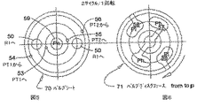
図5及び図6は、固定のバルブシート70と、バルブシート70に適合し、長穴57における高圧及び長穴58における低圧がバルブシート70におけるポート上を通過する際に回転毎に2サイクルの冷却を提供するバルブディスク71とを示す。この設計の新規性は、PT1及びPT2への/からの4つのポートに対するトラック数を、図3に示す4から図5に示す2に低減する手段にある。ポートの1つを細長くすることにより、ポートを通過する際にバルブディスク71の長穴57が同一の幅であるが、V3,V5,ポート53,55を、異なる時間で開口させることが可能である。本例では、ポート55、V5がポート53、V3に比べて細長くされる。同様に、ポートの1つを細長くすることにより、ポートを通過する際にバルブディスク71の長穴58が同一の幅であるが、V4,V6,ポート54,56を、異なる時間で開口させることが可能である。本例では、ポート56、V6がポート54、V4に比べて細長くされる。
FIGS. 5 and 6 show a fixed valve seat 70 and two cycles per rotation as the valve seat 70 fits and the high pressure in the slot 57 and the low pressure in the slot 58 pass over the port in the valve seat 70. A valve disc 71 providing cooling is shown. The novelty of this design lies in the means of reducing the number of tracks for the four ports to / from PT1 and PT2 from 4 shown in FIG. 3 to 2 shown in FIG. By elongating one of the ports, the elongated hole 57 of the valve disc 71 has the same width when passing through the port, but it is possible to open the V3, V5, and the
高圧ガスが中央ポートを通って流れ、低圧ガスが外周を流れるのが好ましいが、流れが逆になるようにバルブを設計することも可能である。本発明の本質的な特徴は、一のトラック上に2つの高圧ポートを有し、第2の単一のトラック上に2つの低圧ポートを有し、各トラック上のポートが異なる開口時間を有することである。 Although it is preferred that the high pressure gas flow through the central port and the low pressure gas flow around the periphery, it is possible to design the valve so that the flow is reversed. An essential feature of the invention is that it has two high pressure ports on one track, two low pressure ports on a second single track, and the ports on each track have different opening times. That is.
尚、本願は、2004年2月11日に出願された米国予備出願番号60/544144の利益を要求する。 This application claims the benefit of US Provisional Application No. 60/544144, filed on Feb. 11, 2004.
Claims (3)
前記ロータリバルブは、バルブシートと、該バルブシートと対向接触しながら相対回転するバルブディスクと、を有し、
前記バルブシートの前記バルブディスクと対向する面に、前記1段目パルスチューブへ流れるガスのためのポートと、前記1段目パルスチューブから流れるガスのためのポートと、前記2段目パルスチューブへ流れるガスのためのポートと、前記2段目パルスチューブから流れるためのポートと、を配置することを特徴とするパルスチューブ冷凍機。 A pulse tube refrigerator comprising a regenerator, a first-stage pulse tube, a second-stage pulse tube, and a rotary valve that controls the flow of gas flowing into the regenerator,
The rotary valve has a valve seat and a valve disc that rotates relative to the valve seat while facing the valve seat,
On the surface of the valve seat facing the valve disk, a port for the gas flowing to the first stage pulse tube, a port for the gas flowing from the first stage pulse tube, and the second stage pulse tube A pulse tube refrigerator comprising: a port for flowing gas; and a port for flowing from the second stage pulse tube.
前記1段目パルスチューブへ流れるガスのためのポートと前記2段目パルスチューブへ流れるガスのためのポートとを、前記蓄冷器へ流れるガスのためのポートよりも内側に配置し、
前記1段目パルスチューブから流れるガスのためのポートと前記2段目パルスチューブから流れるためのポートとを、前記蓄冷器へ流れるガスのためのポートよりも外側に配置することを特徴とする請求項1に記載のパルスチューブ冷凍機。 The surface of the valve seat facing the valve disk further comprises a port for gas flowing to the regenerator,
A port for the gas flowing to the first-stage pulse tube and a port for the gas flowing to the second-stage pulse tube are disposed inside the port for the gas flowing to the regenerator,
The port for the gas flowing from the first-stage pulse tube and the port for flowing from the second-stage pulse tube are arranged outside the port for the gas flowing to the regenerator. Item 2. A pulse tube refrigerator according to item 1.
バルブシートと、
該バルブシートと対向接触しながら相対回転するバルブディスクと、を有し、
前記バルブシートの前記バルブディスクと対向する面に、1段目パルスチューブへ流れるガスのためのポートと、1段目パルスチューブから流れるガスのためのポートと、2段目パルスチューブへ流れるガスのためのポートと、2段目パルスチューブから流れるガスのためのポートと、を配置することを特徴とするロータリバルブ。 A rotary valve that controls the flow of gas flowing into a regenerator of a pulse tube refrigerator,
A valve seat,
A valve disc that rotates relative to the valve seat while facing the valve seat;
A port for the gas flowing to the first stage pulse tube, a port for the gas flowing from the first stage pulse tube, and a gas flowing to the second stage pulse tube on the surface of the valve seat facing the valve disk And a port for the gas flowing from the second-stage pulse tube.
Applications Claiming Priority (2)
| Application Number | Priority Date | Filing Date | Title |
|---|---|---|---|
| US54414404P | 2004-02-11 | 2004-02-11 | |
| US60/544,144 | 2004-02-11 |
Related Parent Applications (1)
| Application Number | Title | Priority Date | Filing Date |
|---|---|---|---|
| JP2006553344A Division JP4884986B2 (en) | 2004-02-11 | 2005-02-09 | 3-track valve for cryogenic refrigerator |
Publications (2)
| Publication Number | Publication Date |
|---|---|
| JP2011237170A true JP2011237170A (en) | 2011-11-24 |
| JP5329607B2 JP5329607B2 (en) | 2013-10-30 |
Family
ID=34860489
Family Applications (2)
| Application Number | Title | Priority Date | Filing Date |
|---|---|---|---|
| JP2006553344A Expired - Fee Related JP4884986B2 (en) | 2004-02-11 | 2005-02-09 | 3-track valve for cryogenic refrigerator |
| JP2011138747A Active JP5329607B2 (en) | 2004-02-11 | 2011-06-22 | Pulse tube refrigerator and rotary valve used therefor |
Family Applications Before (1)
| Application Number | Title | Priority Date | Filing Date |
|---|---|---|---|
| JP2006553344A Expired - Fee Related JP4884986B2 (en) | 2004-02-11 | 2005-02-09 | 3-track valve for cryogenic refrigerator |
Country Status (4)
| Country | Link |
|---|---|
| US (1) | US7549295B2 (en) |
| JP (2) | JP4884986B2 (en) |
| CN (1) | CN100494815C (en) |
| WO (1) | WO2005078363A1 (en) |
Cited By (1)
| Publication number | Priority date | Publication date | Assignee | Title |
|---|---|---|---|---|
| JP2018151128A (en) * | 2017-03-13 | 2018-09-27 | 住友重機械工業株式会社 | Pulse pipe refrigerator and rotary valve unit for pulse pipe refrigerator |
Families Citing this family (17)
| Publication number | Priority date | Publication date | Assignee | Title |
|---|---|---|---|---|
| US7997088B2 (en) * | 2005-01-13 | 2011-08-16 | Sumitomo Heavy Industries, Ltd. | Hybrid spool valve for multi-port pulse tube |
| JP5025643B2 (en) * | 2005-06-10 | 2012-09-12 | 住友重機械工業株式会社 | Multiple rotary valve for pulse tube refrigerator |
| EP2198162A2 (en) * | 2007-09-07 | 2010-06-23 | Renato Bastos Ribeiro | Reciprocating piston cylinder head cover having an integrated fluid exchange rotary disc valve |
| JP4763021B2 (en) | 2008-03-25 | 2011-08-31 | 住友重機械工業株式会社 | Pulse tube refrigerator and regenerative refrigerator |
| GB2463033A (en) * | 2008-08-28 | 2010-03-03 | Siemens Magnet Technology Ltd | Method of operating a cryogenic refrigerator with multiple refrigeration stages |
| JP5172788B2 (en) * | 2009-07-03 | 2013-03-27 | 住友重機械工業株式会社 | 4-valve pulse tube refrigerator |
| JP5362518B2 (en) * | 2009-10-27 | 2013-12-11 | 住友重機械工業株式会社 | Rotary valve and pulse tube refrigerator |
| JP2011094835A (en) * | 2009-10-27 | 2011-05-12 | Sumitomo Heavy Ind Ltd | Pulse tube refrigerator |
| US9644867B2 (en) | 2009-10-27 | 2017-05-09 | Sumitomo Heavy Industries, Ltd. | Rotary valve and a pulse tube refrigerator using a rotary valve |
| JP5497404B2 (en) * | 2009-10-27 | 2014-05-21 | 住友重機械工業株式会社 | Rotary valve and pulse tube refrigerator |
| US20110185747A1 (en) * | 2010-02-03 | 2011-08-04 | Sumitomo Heavy Industries, Ltd. | Pulse tube refrigerator |
| JP5606748B2 (en) * | 2010-02-03 | 2014-10-15 | 住友重機械工業株式会社 | Pulse tube refrigerator |
| KR101342455B1 (en) * | 2010-10-08 | 2013-12-17 | 스미토모 크라이어제닉스 오브 아메리카 인코포레이티드 | Fast cool down cryogenic refrigerator |
| CN102645047B (en) * | 2011-02-22 | 2015-03-11 | 住友重机械工业株式会社 | Ultra-low-temperature pulse-tube refrigerator, method for operating pulse-tube refrigerator, and rotary valve |
| CN102393096A (en) * | 2011-09-29 | 2012-03-28 | 南京柯德超低温技术有限公司 | Pulse tube refrigerator with device capable of automatically regulating gas flow rate and phase |
| JP6913039B2 (en) * | 2018-01-25 | 2021-08-04 | 住友重機械工業株式会社 | Pulse tube refrigerator |
| CN113701391B (en) * | 2021-07-30 | 2022-06-07 | 湖南大学 | Regenerative device and operation method |
Citations (3)
| Publication number | Priority date | Publication date | Assignee | Title |
|---|---|---|---|---|
| JPH09500950A (en) * | 1993-06-03 | 1997-01-28 | ライボルト アクチエンゲゼルシヤフト | Refrigerator operating method and refrigerator suitable for implementing the method |
| JP2002228289A (en) * | 2000-11-30 | 2002-08-14 | Aisin Seiki Co Ltd | Rotary valve unit and pulse pipe refrigerating machine |
| JP2003532045A (en) * | 2000-04-24 | 2003-10-28 | アイジーシー−エーピーディー クライオジェニクス、 インコーポレイテッド | Hybrid two-stage pulse tube refrigerator |
Family Cites Families (20)
| Publication number | Priority date | Publication date | Assignee | Title |
|---|---|---|---|---|
| US3119237A (en) * | 1962-03-30 | 1964-01-28 | William E Gifford | Gas balancing refrigeration method |
| US3205668A (en) * | 1964-01-27 | 1965-09-14 | William E Gifford | Fluid control apparatus |
| US3237421A (en) * | 1965-02-25 | 1966-03-01 | William E Gifford | Pulse tube method of refrigeration and apparatus therefor |
| US3620029A (en) * | 1969-10-20 | 1971-11-16 | Air Prod & Chem | Refrigeration method and apparatus |
| US3625015A (en) * | 1970-04-02 | 1971-12-07 | Cryogenic Technology Inc | Rotary-valved cryogenic apparatus |
| US4430863A (en) * | 1982-06-07 | 1984-02-14 | Air Products And Chemicals, Inc. | Apparatus and method for increasing the speed of a displacer-expander refrigerator |
| GB8816193D0 (en) * | 1988-07-07 | 1988-08-10 | Boc Group Plc | Improved cryogenic refrigerator |
| WO1993010407A1 (en) * | 1991-11-18 | 1993-05-27 | Sumitomo Heavy Industries, Ltd. | Cryogenic refrigerating device |
| US5878580A (en) * | 1993-06-03 | 1999-03-09 | Leybold Aktiengesellschaft | Method of operating a cryogenic cooling device, and a cryogenic cooling device suitable for operation by this method |
| JPH0933124A (en) * | 1995-05-12 | 1997-02-07 | Aisin Seiki Co Ltd | Multistage type pulse pipe refrigerator |
| WO1997008868A1 (en) | 1995-08-25 | 1997-03-06 | Quintet, Inc. | Method of secure communication using signature verification |
| JPH10132404A (en) * | 1996-10-24 | 1998-05-22 | Suzuki Shiyoukan:Kk | Pulse pipe freezer |
| JP2000035253A (en) * | 1998-07-17 | 2000-02-02 | Aisin Seiki Co Ltd | Cooler |
| JP2000074518A (en) * | 1998-08-27 | 2000-03-14 | Aisin Seiki Co Ltd | Cooler |
| JP2000161803A (en) * | 1998-11-27 | 2000-06-16 | Aisin Seiki Co Ltd | Cooling device |
| JP2001280726A (en) * | 2000-03-31 | 2001-10-10 | Aisin Seiki Co Ltd | Pulse pipe refrigerator |
| US6378312B1 (en) * | 2000-05-25 | 2002-04-30 | Cryomech Inc. | Pulse-tube cryorefrigeration apparatus using an integrated buffer volume |
| GB0125084D0 (en) * | 2001-10-19 | 2001-12-12 | Oxford Magnet Tech | Rotary valve |
| JP2003139427A (en) * | 2001-11-05 | 2003-05-14 | Aisin Seiki Co Ltd | Cooling device |
| US6889710B2 (en) * | 2002-11-15 | 2005-05-10 | Air Products And Chemicals, Inc. | Rotary sequencing valve with flexible port plate |
-
2005
- 2005-02-09 JP JP2006553344A patent/JP4884986B2/en not_active Expired - Fee Related
- 2005-02-09 CN CNB2005800043129A patent/CN100494815C/en not_active Expired - Fee Related
- 2005-02-09 US US10/580,924 patent/US7549295B2/en not_active Expired - Fee Related
- 2005-02-09 WO PCT/US2005/004748 patent/WO2005078363A1/en active Application Filing
-
2011
- 2011-06-22 JP JP2011138747A patent/JP5329607B2/en active Active
Patent Citations (3)
| Publication number | Priority date | Publication date | Assignee | Title |
|---|---|---|---|---|
| JPH09500950A (en) * | 1993-06-03 | 1997-01-28 | ライボルト アクチエンゲゼルシヤフト | Refrigerator operating method and refrigerator suitable for implementing the method |
| JP2003532045A (en) * | 2000-04-24 | 2003-10-28 | アイジーシー−エーピーディー クライオジェニクス、 インコーポレイテッド | Hybrid two-stage pulse tube refrigerator |
| JP2002228289A (en) * | 2000-11-30 | 2002-08-14 | Aisin Seiki Co Ltd | Rotary valve unit and pulse pipe refrigerating machine |
Cited By (1)
| Publication number | Priority date | Publication date | Assignee | Title |
|---|---|---|---|---|
| JP2018151128A (en) * | 2017-03-13 | 2018-09-27 | 住友重機械工業株式会社 | Pulse pipe refrigerator and rotary valve unit for pulse pipe refrigerator |
Also Published As
| Publication number | Publication date |
|---|---|
| JP5329607B2 (en) | 2013-10-30 |
| JP4884986B2 (en) | 2012-02-29 |
| US20070119189A1 (en) | 2007-05-31 |
| WO2005078363A1 (en) | 2005-08-25 |
| JP2007522431A (en) | 2007-08-09 |
| US7549295B2 (en) | 2009-06-23 |
| CN1918441A (en) | 2007-02-21 |
| CN100494815C (en) | 2009-06-03 |
Similar Documents
| Publication | Publication Date | Title |
|---|---|---|
| JP4884986B2 (en) | 3-track valve for cryogenic refrigerator | |
| US7654096B2 (en) | Reduced torque valve for cryogenic refrigerator | |
| US7631505B2 (en) | Wearless valve for cryorefrigerator | |
| JP4942897B2 (en) | Hybrid two-stage pulse tube refrigerator | |
| JP5025643B2 (en) | Multiple rotary valve for pulse tube refrigerator | |
| CN101080600B (en) | Reduced input power cryogenic refrigerator | |
| US20170211852A1 (en) | Rotary valve and a pulse tube refrigerator using a rotary valve | |
| JPH10132404A (en) | Pulse pipe freezer | |
| US20120285181A1 (en) | Gas balanced cryogenic expansion engine | |
| JP5497404B2 (en) | Rotary valve and pulse tube refrigerator | |
| JP4281643B2 (en) | Oscillating flow regenerative heat engine | |
| US7509814B2 (en) | Compact integrated buffer for pulse tube refrigerator | |
| TWI803953B (en) | Cryogenic expander | |
| JP2004061031A (en) | Pulse tube refrigerator | |
| JP5362518B2 (en) | Rotary valve and pulse tube refrigerator | |
| JP2004163083A (en) | Rotary valve for refrigerator and refrigerator | |
| JP2005076894A (en) | Regenerative refrigerator | |
| JP2004163082A (en) | Rotary valve for refrigerator and refrigerator | |
| JPH10253186A (en) | Cold storage freezer |
Legal Events
| Date | Code | Title | Description |
|---|---|---|---|
| A131 | Notification of reasons for refusal |
Free format text: JAPANESE INTERMEDIATE CODE: A131 Effective date: 20121113 |
|
| TRDD | Decision of grant or rejection written | ||
| A01 | Written decision to grant a patent or to grant a registration (utility model) |
Free format text: JAPANESE INTERMEDIATE CODE: A01 Effective date: 20130723 |
|
| A61 | First payment of annual fees (during grant procedure) |
Free format text: JAPANESE INTERMEDIATE CODE: A61 Effective date: 20130724 |
|
| R150 | Certificate of patent or registration of utility model |
Ref document number: 5329607 Country of ref document: JP Free format text: JAPANESE INTERMEDIATE CODE: R150 Free format text: JAPANESE INTERMEDIATE CODE: R150 |