JP2011237142A - Cooker - Google Patents
Cooker Download PDFInfo
- Publication number
- JP2011237142A JP2011237142A JP2010110723A JP2010110723A JP2011237142A JP 2011237142 A JP2011237142 A JP 2011237142A JP 2010110723 A JP2010110723 A JP 2010110723A JP 2010110723 A JP2010110723 A JP 2010110723A JP 2011237142 A JP2011237142 A JP 2011237142A
- Authority
- JP
- Japan
- Prior art keywords
- shutter
- heating
- heating chamber
- opening
- preheating
- Prior art date
- Legal status (The legal status is an assumption and is not a legal conclusion. Google has not performed a legal analysis and makes no representation as to the accuracy of the status listed.)
- Granted
Links
Images


Abstract
Description
本発明は、加熱室の加熱室排気口を開閉するシャッターを備えた加熱調理器に関するものである。 The present invention relates to a cooking device including a shutter that opens and closes a heating chamber exhaust port of a heating chamber.
従来の加熱調理器においては、消費電力を低減した加熱調理器が知られている。 In a conventional cooking device, a cooking device with reduced power consumption is known.
そこで、特許文献1に示すように、加熱室の予熱を終了した後、所定時間の間に扉(ドア)が開かれないまま所定時間が経過したら省電力予熱工程に入り、コンベクションヒータのオン−オフデューティーのオンタイムレベルを「省電力」のレベルと加熱室の維持目標温度を下げることで予熱温度維持のための電力消費量を低減し、扉の開閉を検知されると加熱室に食品が入れられたものと判断し、省電力予熱工程を中断して本加熱工程へと進む加熱調理器が開示されている。
Therefore, as shown in
また、特許文献2に示すように、予熱モードを選択した場合には、加熱室上面と下面に設けたヒータに通電され、シャッターが排気通路を閉成して加熱室内からの熱気の排出を最小限にした加熱調理装置が開示されている。 Further, as shown in Patent Document 2, when the preheating mode is selected, the heaters provided on the upper and lower surfaces of the heating chamber are energized, and the shutter closes the exhaust passage to minimize the discharge of hot air from the heating chamber. A limited cooking device is disclosed.
近年、加熱調理器において、手間が掛からないで省エネルギーの加熱調理器が好まれている。 2. Description of the Related Art In recent years, energy-saving cooking devices that do not require time and effort are preferred.
しかし、特許文献1に記載されている加熱調理器は、加熱室の予熱を終了した後、省電力予熱工程に移行した後、加熱室に食品を入れて本加熱工程に移行した場合、省電力予熱工程で加熱室の温度を下げているので本加熱工程に移行した際、再度加熱室の温度を設定した温度まで上昇する必要があり、その際に加熱室には既に食品が入っているので食品への多少の影響は避けられず、加熱室の温度を下げない加熱調理器とは使い勝手が異なる課題がある。
However, the heating cooker described in
また、特許文献2に記載されている加熱調理器は、調理モードが「予熱モード」,「グリルIIモード」,「グリルIモード」,「レンジモード」とそれぞれ独立して設けられているので、例えば予熱後にグリルを行う場合、その度に設定する必要があるので使い勝手が悪いのと、予熱を終了した後に次に使用するモードの設定が必要になるので、その間に加熱室の温度が低下する特許文献1と同様の課題がある。
In addition, since the cooking device described in Patent Document 2 is provided with cooking modes “preheating mode”, “grill II mode”, “grill I mode”, and “range mode”, respectively, For example, when grilling after preheating, it is necessary to set each time, so it is not easy to use, and after setting up the next mode to use, it is necessary to set the temperature of the heating chamber. There is a problem similar to that of
本発明は上記の欠点を解決するためになされたものであり、請求項1では、加熱調理器本体と、該本体内に食品を収納する加熱室と、該加熱室に前記食品を出し入れするためのドアと、該ドアの開閉を検出するドアスイッチと、前記加熱室と前記食品を加熱する電気ヒータと、前記加熱室の温度を検出する温度センサと、前記食品を加熱する加熱方法と温度と時間とを設定する入力手段と、前記加熱を開始させる加熱調理開始スイッチと、前記加熱時に発生する排熱を前記加熱室に設けた加熱室排気口から前記本体外に導く排気ダクトと、前記加熱室で発生した排熱を前記排気ダクト内に流れ込むのを防ぐのに前記排気ダクト内に設け前記加熱室排気口を塞ぐシャッターと、前記シャッターを開閉するシャッター開閉駆動機構と、前記温度センサと前記ドアスイッチと前記電気ヒータへの電力の調整を行い前記シャッター開閉駆動機構へ開閉信号を送る制御部と、を備え、前記制御部は、前記入力手段で予熱工程を行うオーブン加熱を選択して前記加熱調理開始スイッチを入力した後、予熱工程では前記シャッター開閉駆動機構へ前記シャッターを閉じる信号を送り、予熱終了後に前記加熱室に食品を入れた行為が無い場合は前記シャッターを開かないで加熱を継続するものである。
The present invention has been made in order to solve the above-mentioned drawbacks. In
また、請求項2では、前記制御部は、予熱終了後に前記ドアの開閉を検出した後、前記加熱調理開始スイッチの入力を検出すると前記加熱室に食品を入れられたと認識して前記シャッターを開くものである。 According to a second aspect of the present invention, the controller, after detecting the opening / closing of the door after completion of preheating, recognizes that food has been put in the heating chamber when detecting the input of the cooking start switch, and opens the shutter. Is.
さらに、請求項3では、前記制御部は、予熱終了後の予熱待機工程の間に前記加熱室に食品を入れた行為が無い場合は予熱待機工程の終了と同時に前記シャッターを開いて加熱を停止するものである。 Further, in claim 3, when there is no act of putting food in the heating chamber during the preheating standby process after completion of preheating, the controller opens the shutter simultaneously with the end of the preheating standby process and stops heating. To do.
本発明によれば、予熱待機工程中でも加熱室の温度を低下することなく加熱室の加熱された空気の排出を防止して電力の無駄を無くし、一度の設定で予熱工程から予熱待機工程,調理工程と自動で加熱を進行することができ、予熱終了後に食品を入れる行為を行うと調理工程に移行してシャッターを開き、加熱時に食品から出る排熱を排気して良好な調理を実施し、食品を入れるのを忘れた場合はシャッターを開かないで加熱された空気の排出を防止し電力の無駄を無くすことができる。 According to the present invention, even during the preheating standby process, the heated air in the heating chamber is prevented from being discharged without lowering the temperature without reducing the temperature of the heating chamber, so that waste of electric power is eliminated. Heating can proceed automatically with the process, and if the act of putting food after preheating is finished, the process moves to the cooking process, the shutter is opened, exhaust heat emitted from the food is exhausted during heating, and good cooking is performed, If you forget to put in food, you can prevent the heated air from being discharged without opening the shutter, and waste of power can be eliminated.
以下、本発明の実施例を上記した図1〜図10に従って説明する。 Embodiments of the present invention will be described below with reference to FIGS.
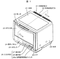
図1は、一実施例の加熱調理器の前面側の斜視図である。図1において、20は加熱調理器の正面に設けられたドア、21は加熱調理器の本体、22はドア20の上部に設けられた取っ手、23はドア20に設けられた耐熱性のガラス窓、24はドア20の下部に設けられた操作パネル、25はドア20の下方に設けられた着脱可能な水タンクであり、過熱水蒸気を作るのに必要な水を溜めておく。 FIG. 1 is a front perspective view of a cooking device according to an embodiment. In FIG. 1, 20 is a door provided in front of the cooking device, 21 is a main body of the cooking device, 22 is a handle provided at the top of the door 20, and 23 is a heat-resistant glass window provided on the door 20. , 24 is an operation panel provided at the lower part of the door 20, and 25 is a detachable water tank provided below the door 20, which stores water necessary for producing superheated steam.
また、26は操作パネル24に設けられた入力手段であって、表示部27,操作部28,加熱調理開始スイッチ28aで構成される。この操作部28を操作することによって、マイクロ波加熱やヒータ加熱などの加熱方法,加熱時間などを設定することができる。29は本体21の上面と左右側面を覆う外枠、30は本体21の背面上部に設けられた外部排気ダクト、31は外部排気ダクト30の上面に設けられた外部排気口である。
Reference numeral 26 denotes input means provided on the operation panel 24, which includes a display unit 27, an
図2は、図1の加熱調理器のA−Aで示した断面における断面図である。図2において、1は加熱室であり、内部に被加熱物である食品を収納する。加熱室1は、加熱室底面1a,加熱室奥壁面1b,加熱室上面1c,加熱室左壁面1eなどで囲まれている。3は加熱室1の上方に設けられた平面状の電気ヒータ、4は加熱室奥壁面1bの後方に設けられた上下2本の棒状の電気ヒータ、5は加熱室奥壁面1bの後方に設けられた送風ファン、5aは送風ファン5を駆動する熱風モータ、6は電気ヒータ4と熱風モータ5aで構成され、加熱室1に熱風を供給する熱風ユニット、6aは熱風ユニット6の背面を構成する熱風ケースであって、熱風モータ5aのモータ軸が貫通する穴が設けられている。7は加熱室左壁面1eの裏側に設けられたボイラー、7aはボイラー7で生成された蒸気を加熱室1に噴き出す噴出口、10は加熱室上面1cの左奥に配置し、制御部11に接続されて加熱室1の温度を検出する温度センサ(例えばサーミスタ)である。13は加熱室底面1aと本体21の底板34の間に設けられた機械室である。機械室13には、水タンク25,重量検出手段32,マグネトロン2,導波管33,回転アンテナ36,パイプ35,回転アンテナ36,回転アンテナ駆動手段37,インバータ基板38,ポンプ手段39,パイプ40等が配置される。41は熱風ユニット6の吸気口である熱風吸気口、42は熱風ユニットの排気口である熱風排気口である。43は重量検出手段32によって支持されるテーブルプレートである。なお、重量検出手段32は、右側重量センサ32a,左側重量センサ32b,奥側重量センサ32cで構成される。
FIG. 2 is a cross-sectional view taken along the line AA of the cooking device of FIG. In FIG. 2,
図2に示すように、加熱室底面1aは、略中央部が凹状に窪んでおり、その中に回転アンテナ36が設置され、マグネトロン2より放射されるマイクロ波エネルギーは、導波管33と回転アンテナ36で拡散されて加熱室1内に放射される。回転アンテナ36は回転アンテナ駆動手段37の出力軸に連結されている。
As shown in FIG. 2, the heating chamber bottom surface 1 a has a substantially recessed central portion, in which a rotating antenna 36 is installed, and the microwave energy radiated from the magnetron 2 rotates with the waveguide 33. It is diffused by the antenna 36 and radiated into the
図3は、本実施例の加熱調理器の内部構造を説明するための斜視図であり、ドア20を開放し、外枠29を省略すると共に、一部構造を透過して表示した。図3において、11はマグネトロン2,回転アンテナ36,熱風ユニット6,電気ヒータ3などを制御する制御部、12はドア20を開放したときに本体21の前面に露出する加熱室縁、20aはドア20の内側の上部に設けられた凸部、12aはドア20を閉じたときに凸部20aによって押されるドアスイッチ、14は機械室13に設けられたモータであり詳細は後述する。45aは後板45の上部に設けられた内部排気口、46は機械室13に設けられマグネトロン2などを冷却するファン装置、47は加熱室1の排気を内部排気口45aに導く排気ダクト、49はモータ14の動力を伝達するシャフトを覆うガードである。
FIG. 3 is a perspective view for explaining the internal structure of the heating cooker of the present embodiment, in which the door 20 is opened, the outer frame 29 is omitted, and a part of the structure is shown in a transparent manner. In FIG. 3, 11 is a control unit for controlling the magnetron 2, the rotating antenna 36, the hot air unit 6, the electric heater 3, etc., 12 is a heating chamber edge exposed on the front surface of the main body 21 when the door 20 is opened, and 20a is a door. Reference numeral 12a denotes a protrusion provided on the inner upper side of the door 20, 12a is a door switch that is pushed by the protrusion 20a when the door 20 is closed, and 14 is a motor provided in the machine room 13. The details will be described later. 45a is an internal exhaust port provided in the upper part of the
図2,図3から分かるように、ドア20を閉めると、ドア20が加熱室縁12と接し、加熱室1を密閉状態に保持し、マイクロ波の漏洩を防止するとともに、ヒータの熱や過熱水蒸気を封じ込める。このとき、ドア20に設けられた凸部20aがドアスイッチ12aの接点を閉成し、ドア20を開くとドアスイッチ12aの接点を開成するので、制御部11はドア20の開閉状態を検出できる。
As can be seen from FIGS. 2 and 3, when the door 20 is closed, the door 20 comes into contact with the heating chamber edge 12, holds the
次に、図4の斜視図を用いて、排気ダクト47の構造を説明する。排気ダクト47は、側面47c,側面47d,壁面47e,裏面47g,上面47fで構成される略L字のダクトであり、ダクトの風上側にはダクト入気口47h,ダクトの風下側にはダクト排気口47jが設けられている。また、側面47cと側面47dには、各々穴47a,47bが設けられている。これらの穴47a,47bについては後述する。
Next, the structure of the exhaust duct 47 will be described using the perspective view of FIG. The exhaust duct 47 is a substantially L-shaped duct composed of a side surface 47c, a side surface 47d, a
次に、図9,図10の断面図を用いて、排気ダクト47近傍の詳細な構造を説明する。図9はシャッター9を閉鎖したときの加熱調理器の断面図である。ここに示すように、図3で示したファン装置46から供給された本体冷却風53は、後板45に設けられた鎧戸穴45bを通って、外部排気ダクト30に供給され、その上面に設けられた外部排気口31から排気される。また、加熱室上面1cに設けられた加熱室排気口8はシャッター9によって封鎖されているため、排気ダクト47には加熱室1内の熱が流入しない。なお、加熱室1内の熱の大部分を保持できるのであれば、多少の熱漏れがあっても良い。
Next, a detailed structure in the vicinity of the exhaust duct 47 will be described with reference to cross-sectional views of FIGS. FIG. 9 is a sectional view of the heating cooker when the
一方、図10に示すように、シャッター9が排気ダクト47内で傾斜して開放されているときには、加熱室1の排熱52は、加熱室排気口8の全穴群を覆う排気ダクト47,内部排気口45aを通って、外部排気ダクト30に供給される。また、本体冷却風53も外部排気ダクト30に供給される。従って、外部排気ダクト30内で排熱52と本体冷却風53が混じり、比較的低い温度の排熱として外部排気口31から排気される。なお、ここでは、加熱室排気口8をφ4の穴群で構成されるものとするが、排気口としての役割を果たす限り、加熱室排気口8の大きさ,形状,数は図示したものに限定されない。
On the other hand, as shown in FIG. 10, when the
次に、図9と図10を用いて、シャッター9の構成および動作をより詳細に説明する。シャッター9はダクト入気口47よりも一回り小さい略長方形の鋼鉄片であり、排気ダクト47の壁面47e側に設けられたシャッター軸48を支点として開閉する。シャッター軸48は、図4で説明した穴47a,48bに回転自在に支持されている。シャッター9の先端9dは、排熱52の流れを妨げないように、風下側に曲げられた形状となっている。さらに、シャッター9は、シャッター9と長手方向を同じくするビード9b(凸状の絞り)と、両短辺を風下側に折り曲げた外周立ち上げ部9cを備えることによって、強度を増している。
Next, the configuration and operation of the
図9に示すように、本実施例では、シャッター9を閉鎖したとき、先端9dが加熱室上面1cに接触するが、シャッター軸48側は加熱室上面1cには接しない。このように構成したのは、シャッター9と加熱室上面1cとの接触面積を小さくし、シャッター9の回動を容易なものとするためである。また、シャッター9はダクト入気口47hよりも一回り小さいため、シャッター9の外周には隙間が生じる。このような構成のため、加熱室排気口8とダクト47がシャッター9によって完全に分離されるわけではないが、シャッター9の存在により通風抵抗が大きくなるため、加熱室1からの排気ダクト47への排熱52の漏れを無視できる程度に抑えることができる。
As shown in FIG. 9, in this embodiment, when the
また、図10に示すように、シャッター9を開放したときには、シャッター9は水平よりも約50度傾斜した状態で停止する。このとき、先端9dを上面47fに接触させても良いし、接触させなくても良い。これらを接触させたときには、排熱52がシャッター9の裏側に回り込むのを抑制できるので、より効率よく排熱52を排気することができる。また、これらを接触させないときには、シャッター9の開閉にステッピングモータを用いるときの制御を簡易にすることができる。
Further, as shown in FIG. 10, when the
次に、図13を用いて、排気ダクト47の構成と、シャッター9の取り付け位置の関係をより詳細に説明する。図13に示すように、排気ダクト47は、加熱室上面1cに設けたリブで構成した下側と、それとは別部品である上側とで構成される。このため、排気ダクト47の上側と下側の間には、わずかながら隙間が存在する。しかしながら、本実施例では、シャッター9を、隙間の風上に配置したため、シャッター9によって加熱室排気口8を閉鎖できるのであれば、シャッター9の上方にある隙間からの排熱52の漏洩を防止することができる。このように、排気ダクト47の断面形状を略L字とし、排気ダクト47の隙間よりも下方にシャッター9を配置したので、排気ダクト47の隙間から排熱52が漏洩するのを抑制することができる。
Next, the relationship between the configuration of the exhaust duct 47 and the mounting position of the
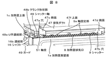
次に、図7と図8の斜視図を用いて、シャッター9の開閉機構を説明する。図7はシャッター9が閉鎖した状態を示す図であり、図8はシャッター9が開放した状態を示す図である。
Next, the opening / closing mechanism of the
図7に示すように、シャッター軸48は、シャッター9の軸固定部9aに固定されており、穴47a,47bに回転自在に支持されている。また、シャッター軸48は、排気ダクト47の外部で軸受51によって回転自在に支持されている。さらに、このシャッター軸48は軸受51の外側となる方向に、クランク形状部48bと、U字連結部48aを備えている。U字連結部48aには、シャフト16の連結部16bが連結されている。シャフト16を上下すると、その上下運動がシャッター軸48のクランク形状部48bによって回転運動に変換され、シャッター軸48を回転させることができる。なお、シャフト16は、ガード49によって覆われており、その上下運動が電気部品のリード線などによって妨げられるのを防止している。そして、図8に示すように、シャフト16を上方向に移動させると、シャッター軸48が回転し、シャッター9が開放される。この結果、加熱室排気口8が露出し、加熱室1の排熱52を排気ダクト47に排気することができる。
As shown in FIG. 7, the
次に、図5の斜視図を用いて、シャッター開閉駆動機構17の構成を説明する。シャッター開閉駆動機構17は、モータ14と、モータ14のクランク状の腕部15と、シャフト16で構成される。図5に示すように、シャフト16の下方には、モータ支持部50に支持されたモータ14が設けられており、シャフト16の下端は、モータ14の腕部15に連結されている。本実施例では、モータ14として、制御部11からの制御信号に基づいて制御されるステッピングモータを用い回転角度を制御よく制御できるものとするが、DCモータを用いても良い。制御部11からの制御信号に基づき、モータ14の腕部15を所定量回転させることで、シャフト16の上端を所望の量だけ上下させることができ、シャッター9を任意に開閉することができる。なお、高温となる加熱室1よりも下方にモータ14を設け、また、ファン装置46による冷却をしやすい位置にモータ14を配置したので、容易にモータ14を低温に保つことができる。
Next, the configuration of the shutter opening / closing drive mechanism 17 will be described using the perspective view of FIG. The shutter opening / closing drive mechanism 17 includes a motor 14, a crank-shaped arm portion 15 of the motor 14, and a
次に、図6を用いて、モータ14の腕部15の構成をより詳細に説明する。腕部15は、円筒部15a,カギ部15b,支点部15cから構成されている。支点部15cはモータ14の回転軸に固定されており、その回転と共に回転する。支持部15cが回転すると、それを回転中心にカギ部15bが移動する。カギ部15bには回転自在に円筒部15aが挿入されており、支持部15cの回転に伴い円筒部15aが上下する。円筒部15aには、シャフト16の下端のリング部16aが連結されているため、モータ14の回転軸を回転させることで、シャフト16を上下に動かすことができる。
Next, the configuration of the arm portion 15 of the motor 14 will be described in more detail with reference to FIG. The arm portion 15 includes a cylindrical portion 15a, a key portion 15b, and a fulcrum portion 15c. The fulcrum portion 15c is fixed to the rotating shaft of the motor 14, and rotates with the rotation. When the support portion 15c rotates, the key portion 15b moves around the rotation center. A cylindrical portion 15a is rotatably inserted into the key portion 15b, and the cylindrical portion 15a moves up and down as the support portion 15c rotates. Since the ring portion 16a at the lower end of the
以上の構成からなり、予熱工程を行うオーブン加熱時のシャッター9の動作について、図11と図12を用いて詳細に説明する。
The operation of the
図11において、オーブン加熱は、加熱室1の温度を設定温度まで加熱する予熱工程と、予熱後食品が加熱室1に入れられるまで設定温度を所定時間の間保持する予熱待機工程と、食品を入れて設定された時間加熱を行う調理工程の3工程に分けられる。
In FIG. 11, the oven heating includes a preheating step of heating the temperature of the
オーブン調理を開始するために入力手段26でオーブン加熱を選択し、設定温度と加熱時間を設定し、加熱調理開始スイッチ28aを操作すると予熱工程へと進み加熱が開始する。 When oven heating is selected with the input means 26 to start oven cooking, a set temperature and a heating time are set, and the heating cooking start switch 28a is operated, the process proceeds to a preheating step and heating is started.
予熱工程では、加熱室1で加熱された空気が無駄に排出されるのを防止するためにシャッター9を閉じ、加熱室1の温度を設定温度まで加熱するように、制御部11によって加熱室1内の温度を温度センサ10によって検出し電気ヒータ4への電力の調整が行われる。
In the preheating step, the
シャッター9を閉じるのには、制御部11はモータ14に反時計回転方向に100度回転する信号を送ることで、腕部15が反時計方向に回転(図6、矢印ハ方向)して、シャフト16を下方に引き下げクランク状に曲げられたシャッター軸48を回転してシャッター9を回転し、加熱室排気口8を加熱室上面1cの外側から略塞ぐようにシャッター9の先端9dを加熱室上面1cに接して停止する。
To close the
シャッター9を開くときは約50度回転させるための回転角度が制御部11から指示されてモータ14が回転するのに対して、シャッター9を閉じて加熱室排気口8を略塞ぐときはシャッター9を約55度回転させるための回転角度が制御部11から指示されてモータ14が回転するので、シャッター9が閉成した後もモータ14は回転を続けようと動作した後に停止する。そのため、製造過程などで発生した組み立て誤差に影響されることなく、シャッター9は確実に閉じることが可能となる。
When the
加熱室1の加熱が進行し、加熱室1の温度が設定温度の300℃に越した時点で予熱終了の報知を行い次の予熱待機工程へと進む。
When the heating of the
予熱待機工程では、加熱室1の温度を設定温度の300℃に維持して加熱室1に食品の入れられるのを待つ工程で、食品を加熱室1に入れるためにドア20を開くことでドアスイッチ12aが動作し、制御部11はドアスイッチ12aの接点の状態でドア20が開成したことを検出して予熱待機工程を終了し、加熱室1に食品を入れてドア20を閉めて加熱調理開始スイッチ28aを再操作することで次の調理工程が開始する。
In the preheating standby process, the temperature of the
制御部11は、加熱室1に食品を入れられた行為として、ドア20を開成した時、ドア20を開閉(開成した後に閉成)した時、もしくは、ドア20の開閉後に加熱調理開始スイッチ28aの入力を検出することで認識している。そして、加熱室1に食品を入れられた行為を認識するとシャッター9を開成するようにモータ14へ信号を送る。
The control unit 11 performs an operation of putting food in the
本実施例では、ドア20の開閉後に加熱調理開始スイッチ28aの入力を検出した場合に加熱室1に食品を入れられた行為と認識してシャッター9を開くようにしている。
In this embodiment, when the input of the heating cooking start switch 28a is detected after the door 20 is opened and closed, the
調理工程では、シャッター9を開いて、食品を加熱している時に、食品から出る蒸気や油煙を外部排気口31より排出し、設定された加熱時間が経過すると調理工程を終了する。
In the cooking process, when the
シャッター9を約50度開くために、制御部11はモータ14に時計回転方向に回転する信号を送ることで、腕部15が回転して、シャフト16を上方に押し上げクランク形状部48bを備えるシャッター軸48を回転し、加熱室排気口8を加熱室1の外側から略塞いでいる状態からシャッター9は約50度回転してシャッター9の先端9dを排気ダクト47の上面47fに略当接し傾斜した状態で停止する。
In order to open the
シャッター9を閉じた状態から開くとき、シャッター9の先端9dのみが加熱室上面1cに触れているので(接触面積が少ない)、例え油煙により排気ダクト47内やシャッター9に油が付着し、加熱室排気口8の外側に油が溜まってべた付いた状態でも、シャッター9をスムーズに開くことが可能である。
When the
また、シャッター9を開いた状態から閉じるときも同様に、シャッター9をスムーズに閉じることが可能である。
Similarly, when the
また、シャッター9を開成したとき、排気ダクト47内で傾斜して停止するので排熱52をスムーズに排出できる。
In addition, when the
次に、予熱終了の報知音に気づかなかった場合について図11を用いて説明する。 Next, a case where the notification sound of the end of preheating is not noticed will be described with reference to FIG.
図12において、前述した予熱工程を行うオーブン加熱で、予熱終了の報知に気づかないで予熱待機工程の所定時間内に食品を入れるのを忘れた(食品を入れた行為が無い)場合、無駄な電力の消費を最低限にするように、所定時間を予熱待機工程を継続した後はシャッター9を閉じたままの状態で自動的に調理工程に進み、設定された加熱時間が経過すると加熱室1内の排熱を排気できるようにシャッター9を開いて調理工程を終了する。
In FIG. 12, in the oven heating in which the above-described preheating process is performed, if the user forgets to put the food within the predetermined time of the preheating standby process without noticing the notice of the end of the preheating (there is no act of putting the food), it is useless. After continuing the preheating standby process for a predetermined time so as to minimize power consumption, the process automatically proceeds to the cooking process with the
また、予熱待機工程を所定時間経過した後は、シャッター9を開いて加熱を終了してもよい。
Further, after a predetermined time has elapsed in the preheating standby process, the
この時、全工程においてシャッター9を閉じたまま加熱されるので、加熱室1の熱が排出され難い状態なので消費電力が少なくて済む。
At this time, since heating is performed with the
以上説明したように、本発明によれば、予熱待機工程中でも加熱室の温度を低下することなく加熱室の加熱された空気の排出を防止して電力の無駄を無くし、一度の設定で予熱工程から予熱待機工程,調理工程と自動で加熱を進行することができ、予熱終了後に食品を入れる行為を行うと調理工程に移行してシャッターを開き、加熱時に食品から出る排熱を排気して良好な調理を実施し、食品を入れるのを忘れた場合はシャッターを開かないで加熱された空気の排出を防止し電力の無駄を無くすことができる。 As described above, according to the present invention, it is possible to prevent discharge of heated air in the heating chamber without reducing the temperature of the heating chamber even during the preheating standby step, thereby eliminating waste of power, and the preheating step in one setting. Heating can proceed automatically from the preheating standby process to the cooking process, and if the action of putting food after the preheating is completed, the process moves to the cooking process and the shutter is opened to exhaust the exhaust heat from the food during heating. If the user forgets to put in food and does not open the shutter, the heated air can be prevented from being discharged without opening the shutter, and waste of electric power can be eliminated.
1 加熱室
2 マグネトロン
3,4 電気ヒータ
5 送風ファン
6 熱風ユニット
7 ボイラー
8 加熱室排気口
9 シャッター
10 温度センサ
11 制御部
13 機械室
14 モータ
15 腕部
16 シャフト
17 シャッター開閉駆動機構
20 ドア
DESCRIPTION OF
Claims (3)
前記制御部は、前記入力手段で予熱工程を行うオーブン加熱を選択して前記加熱調理開始スイッチを入力した後、予熱工程では前記シャッター開閉駆動機構へ前記シャッターを閉じる信号を送り、予熱終了後に前記加熱室に食品を入れた行為が無い場合は前記シャッターを開かないで加熱を継続する事を特徴とする加熱調理器。 A main body of a heating cooker, a heating chamber for storing food in the main body, a door for putting food in and out of the heating chamber, a door switch for detecting opening and closing of the door, the heating chamber and the food An electric heater that heats the food, a temperature sensor that detects the temperature of the heating chamber, an input means that sets a heating method and temperature and time for heating the food, a cooking start switch that starts the heating, An exhaust duct for guiding exhaust heat generated during heating to the outside of the main body from a heating chamber exhaust port provided in the heating chamber, and the exhaust duct for preventing exhaust heat generated in the heating chamber from flowing into the exhaust duct A shutter for closing the heating chamber exhaust port, a shutter opening / closing drive mechanism for opening / closing the shutter, adjusting the power to the temperature sensor, the door switch, and the electric heater to adjust the power. And a control unit sending a closing signal to the coater opening and closing mechanism, and
The controller selects oven heating to perform a preheating process with the input means and inputs the cooking start switch, and then sends a signal to close the shutter to the shutter opening / closing drive mechanism in the preheating process, and after the preheating ends A heating cooker characterized in that heating is continued without opening the shutter when there is no act of putting food in the heating chamber.
Priority Applications (1)
| Application Number | Priority Date | Filing Date | Title |
|---|---|---|---|
| JP2010110723A JP5517735B2 (en) | 2010-05-13 | 2010-05-13 | Cooker |
Applications Claiming Priority (1)
| Application Number | Priority Date | Filing Date | Title |
|---|---|---|---|
| JP2010110723A JP5517735B2 (en) | 2010-05-13 | 2010-05-13 | Cooker |
Publications (2)
| Publication Number | Publication Date |
|---|---|
| JP2011237142A true JP2011237142A (en) | 2011-11-24 |
| JP5517735B2 JP5517735B2 (en) | 2014-06-11 |
Family
ID=45325319
Family Applications (1)
| Application Number | Title | Priority Date | Filing Date |
|---|---|---|---|
| JP2010110723A Active JP5517735B2 (en) | 2010-05-13 | 2010-05-13 | Cooker |
Country Status (1)
| Country | Link |
|---|---|
| JP (1) | JP5517735B2 (en) |
Cited By (2)
| Publication number | Priority date | Publication date | Assignee | Title |
|---|---|---|---|---|
| CN106419619A (en) * | 2016-10-11 | 2017-02-22 | 广州极效能源科技有限公司 | Energy-collecting air guide structure used on electric oven |
| CN107850314A (en) * | 2015-09-02 | 2018-03-27 | 松下知识产权经营株式会社 | Heating device |
Citations (10)
| Publication number | Priority date | Publication date | Assignee | Title |
|---|---|---|---|---|
| JPS57187532A (en) * | 1981-05-13 | 1982-11-18 | Matsushita Electric Ind Co Ltd | Heater |
| JPS63155904U (en) * | 1987-03-31 | 1988-10-13 | ||
| JPS6413007U (en) * | 1987-07-11 | 1989-01-24 | ||
| JPH0351628A (en) * | 1989-07-19 | 1991-03-06 | Sanyo Electric Co Ltd | Heating cooking device |
| JP2005226872A (en) * | 2004-02-10 | 2005-08-25 | Matsushita Electric Ind Co Ltd | Heating cooker and heating cooking method |
| JP2006046715A (en) * | 2004-08-02 | 2006-02-16 | Sharp Corp | Steam cooking device |
| JP2007263460A (en) * | 2006-03-28 | 2007-10-11 | Osaka Gas Co Ltd | Heating cooker |
| JP2009250492A (en) * | 2008-04-04 | 2009-10-29 | Hitachi Appliances Inc | Heating cooker |
| JP2010038373A (en) * | 2008-07-31 | 2010-02-18 | Sharp Corp | Cooker |
| JP2010054097A (en) * | 2008-08-27 | 2010-03-11 | Sharp Corp | Heating cooker |
-
2010
- 2010-05-13 JP JP2010110723A patent/JP5517735B2/en active Active
Patent Citations (10)
| Publication number | Priority date | Publication date | Assignee | Title |
|---|---|---|---|---|
| JPS57187532A (en) * | 1981-05-13 | 1982-11-18 | Matsushita Electric Ind Co Ltd | Heater |
| JPS63155904U (en) * | 1987-03-31 | 1988-10-13 | ||
| JPS6413007U (en) * | 1987-07-11 | 1989-01-24 | ||
| JPH0351628A (en) * | 1989-07-19 | 1991-03-06 | Sanyo Electric Co Ltd | Heating cooking device |
| JP2005226872A (en) * | 2004-02-10 | 2005-08-25 | Matsushita Electric Ind Co Ltd | Heating cooker and heating cooking method |
| JP2006046715A (en) * | 2004-08-02 | 2006-02-16 | Sharp Corp | Steam cooking device |
| JP2007263460A (en) * | 2006-03-28 | 2007-10-11 | Osaka Gas Co Ltd | Heating cooker |
| JP2009250492A (en) * | 2008-04-04 | 2009-10-29 | Hitachi Appliances Inc | Heating cooker |
| JP2010038373A (en) * | 2008-07-31 | 2010-02-18 | Sharp Corp | Cooker |
| JP2010054097A (en) * | 2008-08-27 | 2010-03-11 | Sharp Corp | Heating cooker |
Cited By (5)
| Publication number | Priority date | Publication date | Assignee | Title |
|---|---|---|---|---|
| CN107850314A (en) * | 2015-09-02 | 2018-03-27 | 松下知识产权经营株式会社 | Heating device |
| JPWO2017038021A1 (en) * | 2015-09-02 | 2018-06-14 | パナソニックIpマネジメント株式会社 | Cooker |
| EP3346189A4 (en) * | 2015-09-02 | 2018-08-29 | Panasonic Intellectual Property Management Co., Ltd. | Cooking apparatus |
| US10895385B2 (en) * | 2015-09-02 | 2021-01-19 | Panasonic Intellectual Property Management Co., Ltd. | Cooking apparatus |
| CN106419619A (en) * | 2016-10-11 | 2017-02-22 | 广州极效能源科技有限公司 | Energy-collecting air guide structure used on electric oven |
Also Published As
| Publication number | Publication date |
|---|---|
| JP5517735B2 (en) | 2014-06-11 |
Similar Documents
| Publication | Publication Date | Title |
|---|---|---|
| SG175216A1 (en) | Cooking appliance | |
| KR20080025603A (en) | Heating cooker and method for controlling the same | |
| EP2051013B1 (en) | Cooking device | |
| JP4982282B2 (en) | Induction heating cooker | |
| WO2015141206A1 (en) | Heating cooker | |
| JP5517735B2 (en) | Cooker | |
| JP4000531B2 (en) | Cooker | |
| JP6761977B2 (en) | Cooker | |
| JP5517747B2 (en) | Cooker | |
| JP4251156B2 (en) | Cooker | |
| JP5517734B2 (en) | Cooker | |
| JP4627057B2 (en) | Cooker | |
| JP3762727B2 (en) | Cooker | |
| JP5766056B2 (en) | Cooker | |
| JPH1019269A (en) | Microwave oven | |
| JP2004044846A (en) | High-frequency heating cooker | |
| JP7086023B2 (en) | Cooker | |
| JP2016056981A (en) | Heating cooker | |
| JP2007229282A (en) | Rice cooker | |
| JP2010127545A (en) | Cooking device | |
| JPH05103719A (en) | Rice cooker | |
| JP6530973B2 (en) | High frequency heating cooker | |
| JP6179311B2 (en) | Home bakery | |
| EP2224786B1 (en) | Cooking apparatus | |
| JP2015094507A (en) | Heating cooker |
Legal Events
| Date | Code | Title | Description |
|---|---|---|---|
| A521 | Written amendment |
Free format text: JAPANESE INTERMEDIATE CODE: A523 Effective date: 20120307 |
|
| A521 | Written amendment |
Free format text: JAPANESE INTERMEDIATE CODE: A821 Effective date: 20120307 |
|
| A621 | Written request for application examination |
Free format text: JAPANESE INTERMEDIATE CODE: A621 Effective date: 20120803 |
|
| A521 | Written amendment |
Free format text: JAPANESE INTERMEDIATE CODE: A523 Effective date: 20120803 |
|
| A977 | Report on retrieval |
Free format text: JAPANESE INTERMEDIATE CODE: A971007 Effective date: 20130807 |
|
| A131 | Notification of reasons for refusal |
Free format text: JAPANESE INTERMEDIATE CODE: A131 Effective date: 20130820 |
|
| A521 | Written amendment |
Free format text: JAPANESE INTERMEDIATE CODE: A523 Effective date: 20131001 |
|
| TRDD | Decision of grant or rejection written | ||
| A01 | Written decision to grant a patent or to grant a registration (utility model) |
Free format text: JAPANESE INTERMEDIATE CODE: A01 Effective date: 20140304 |
|
| A61 | First payment of annual fees (during grant procedure) |
Free format text: JAPANESE INTERMEDIATE CODE: A61 Effective date: 20140401 |
|
| R150 | Certificate of patent or registration of utility model |
Ref document number: 5517735 Country of ref document: JP Free format text: JAPANESE INTERMEDIATE CODE: R150 |
|
| S531 | Written request for registration of change of domicile |
Free format text: JAPANESE INTERMEDIATE CODE: R313531 |
|
| S533 | Written request for registration of change of name |
Free format text: JAPANESE INTERMEDIATE CODE: R313533 |
|
| R350 | Written notification of registration of transfer |
Free format text: JAPANESE INTERMEDIATE CODE: R350 |