JP2011226257A - Safety device for construction equipment - Google Patents
Safety device for construction equipment Download PDFInfo
- Publication number
- JP2011226257A JP2011226257A JP2011085433A JP2011085433A JP2011226257A JP 2011226257 A JP2011226257 A JP 2011226257A JP 2011085433 A JP2011085433 A JP 2011085433A JP 2011085433 A JP2011085433 A JP 2011085433A JP 2011226257 A JP2011226257 A JP 2011226257A
- Authority
- JP
- Japan
- Prior art keywords
- safety device
- drive unit
- construction machine
- movable range
- unit
- Prior art date
- Legal status (The legal status is an assumption and is not a legal conclusion. Google has not performed a legal analysis and makes no representation as to the accuracy of the status listed.)
- Granted
Links
Images
Classifications
-
- E—FIXED CONSTRUCTIONS
- E21—EARTH DRILLING; MINING
- E21B—EARTH DRILLING, e.g. DEEP DRILLING; OBTAINING OIL, GAS, WATER, SOLUBLE OR MELTABLE MATERIALS OR A SLURRY OF MINERALS FROM WELLS
- E21B7/00—Special methods or apparatus for drilling
- E21B7/02—Drilling rigs characterized by means for land transport with their own drive, e.g. skid mounting or wheel mounting
- E21B7/024—Drilling rigs characterized by means for land transport with their own drive, e.g. skid mounting or wheel mounting having means for adapting to inclined terrain; having means for stabilizing the vehicle while drilling
-
- E—FIXED CONSTRUCTIONS
- E02—HYDRAULIC ENGINEERING; FOUNDATIONS; SOIL SHIFTING
- E02F—DREDGING; SOIL-SHIFTING
- E02F9/00—Component parts of dredgers or soil-shifting machines, not restricted to one of the kinds covered by groups E02F3/00 - E02F7/00
- E02F9/24—Safety devices, e.g. for preventing overload
-
- E—FIXED CONSTRUCTIONS
- E21—EARTH DRILLING; MINING
- E21B—EARTH DRILLING, e.g. DEEP DRILLING; OBTAINING OIL, GAS, WATER, SOLUBLE OR MELTABLE MATERIALS OR A SLURRY OF MINERALS FROM WELLS
- E21B41/00—Equipment or details not covered by groups E21B15/00 - E21B40/00
- E21B41/0021—Safety devices, e.g. for preventing small objects from falling into the borehole
-
- E—FIXED CONSTRUCTIONS
- E21—EARTH DRILLING; MINING
- E21B—EARTH DRILLING, e.g. DEEP DRILLING; OBTAINING OIL, GAS, WATER, SOLUBLE OR MELTABLE MATERIALS OR A SLURRY OF MINERALS FROM WELLS
- E21B7/00—Special methods or apparatus for drilling
- E21B7/02—Drilling rigs characterized by means for land transport with their own drive, e.g. skid mounting or wheel mounting
- E21B7/022—Control of the drilling operation; Hydraulic or pneumatic means for activation or operation
Abstract
Description
本発明は、請求項1記載の通り、キャリアユニット及びそのキャリアユニットに対し可動な駆動ユニットを有する建設機械用安全装置に関する。 The present invention relates to a safety device for a construction machine having a carrier unit and a drive unit movable relative to the carrier unit.
アースドリル機等の大型建設機械では稼働中に傾きモーメントが発生することがある。その傾きモーメントには、積載物の出っ張り等が原因で生じる静的なものと、遠心力等が原因で生じる動的なものとがある。 In large construction machines such as earth drill machines, tilt moments may occur during operation. The tilt moment includes a static one caused by the bulging of the load and a dynamic one caused by centrifugal force.
過剰な傾きモーメントが生じることを防ぐには、例えば、積載物の出っ張り方を制限すればよいことがわかっている。しかし、そのような制限を課すとその建設機械の可動範囲が狭くなる。ひいては、その建設機械の利用可能範囲が限られてしまう。 In order to prevent an excessive tilt moment from occurring, for example, it has been found that it is only necessary to limit the way in which the load is projected. However, imposing such restrictions narrows the range of movement of the construction machine. Eventually, the usable range of the construction machine is limited.
本発明の目的は、その建設機械の稼働時信頼性特に対傾き安全性を大きく高めるのと同時に、その建設機械の作業半径を大きく拡げ、用途を大きく増やし強め且つ効率を大きく高めることが可能な、建設機械用安全装置を提供することである。 It is an object of the present invention to greatly increase the operating reliability of the construction machine, in particular, the anti-tilt safety, and at the same time, greatly increase the working radius of the construction machine, greatly increase the use and increase the efficiency. It is to provide a safety device for construction machinery.
この目的を達成すべく、請求項1記載の特徴を有する安全装置を提案する。他の請求項に記載したのはその好適な実施形態である。 In order to achieve this object, a safety device having the features of claim 1 is proposed. Other claims are preferred embodiments thereof.
即ち、本発明に係る安全装置は、キャリアユニット及びそのキャリアユニットに対し可動な駆動ユニットを有する建設機械用の安全装置であって、キャリアユニットに対する駆動ユニットの現在位置を検出する1個又は複数個の検出手段と、キャリアユニットに対する駆動ユニットの現在位置を表示する表示手段と、建設機械の傾きに対し所与レベルの安全性を提供しつつ駆動ユニットを動かせる可動範囲を1個又は複数個の入力値に基づき1個又は複数個定める評価ユニットと、を備え、駆動ユニットの現在位置と併せその可動範囲をその表示手段で表示させるものである。 That is, the safety device according to the present invention is a safety device for a construction machine having a carrier unit and a drive unit movable with respect to the carrier unit, and detects one or more of the current position of the drive unit with respect to the carrier unit. One or more inputs of a detection means, a display means for displaying the current position of the drive unit relative to the carrier unit, and a movable range in which the drive unit can be moved while providing a given level of safety against the inclination of the construction machine One or a plurality of evaluation units determined based on the values, and the movable range is displayed on the display means together with the current position of the drive unit.
本発明の基礎をなしている知識は、キャリアユニットで支持される駆動ユニットに重量があるため、キャリアユニットに対する駆動ユニット位置の調整中に、重心位置がずれて変動的な傾きモーメントが発生する、という知識である。そうした変動的な傾きモーメントに対抗して対傾き安全稼働を実現するため、本発明では、キャリアユニットに対し駆動ユニットを安全に動かせる可動範囲を、評価ユニットで定めるようにしている。可動範囲は、所定の傾き安全性要因が見られること等を特徴とするものであるので、それを定めるには、相応の特性曲線乃至チャートを評価ユニット内に格納等しておくこともできる。評価ユニットで可動範囲を定める処理は、1個又は複数個の入力値に基づき実行される。即ち、包括的な検討を踏まえ、評価ユニットでは、傾き方が駆動ユニットの出っ張りによって左右される事実や他の諸要因(例えば駆動ユニット上の積載物や建設機械の力学的状態)の影響を受ける事実を反映させることができる。例えば、駆動ユニットによってドリルパイプが保持されている場合、そのドリルパイプの直径を上述した入力値の一つとして利用することで、そのドリルパイプの関連部分質量が傾きモーメントに及ぼす影響を反映させることができる。 The knowledge that forms the basis of the present invention is that since the drive unit supported by the carrier unit is heavy, during the adjustment of the drive unit position relative to the carrier unit, the position of the center of gravity shifts and a variable tilt moment occurs. It is knowledge that. In the present invention, the evaluation unit defines a movable range in which the drive unit can be safely moved with respect to the carrier unit in order to realize the anti-tilt safe operation against such a variable tilt moment. Since the movable range is characterized in that a predetermined tilt safety factor is found, for example, a corresponding characteristic curve or chart can be stored in the evaluation unit. The process of determining the movable range by the evaluation unit is executed based on one or a plurality of input values. In other words, based on comprehensive considerations, the evaluation unit is affected by the fact that the way of tilting depends on the protrusion of the drive unit and other factors (for example, the load on the drive unit and the mechanical state of the construction machine). The facts can be reflected. For example, when a drill pipe is held by a drive unit, the diameter of the drill pipe is used as one of the input values described above to reflect the influence of the associated partial mass of the drill pipe on the tilt moment. Can do.
更に、本発明における表示手段では、求まった安全な可動範囲及び実際に調整される駆動ユニットの現在位置の双方がオペレータ向けにまとめて表示される。オペレータは、その表示を一目で看取することができ、それを通じ、駆動ユニットの現在位置が安全な可動範囲の中心か(高安定領域内か)それとも安全な可動範囲の辺縁部での稼働となっているか(駆動ユニットをそれ以上出っ張らせることが不可能と見られるか)を知ることができる。従って、オペレータは、更なる対傾き安全性向上手段(例えば動的な力の制限)が必要であるか否かを早期段階で知ることもできるので、極めて高い効率及び安全性での稼働が実現されることとなる。即ち、本発明によれば、対傾き安全性の現状が可視表示されるため、オペレータがそれを極めて容易且つ直観的に把握することができ、それによって極めて高い稼働時信頼性が実現されることとなる。 Furthermore, in the display means in the present invention, both the obtained safe movable range and the current position of the actually adjusted drive unit are displayed together for the operator. The operator can see the display at a glance, through which the current position of the drive unit is at the center of the safe movable range (within the high stability range) or at the edge of the safe movable range (Whether it seems impossible to project the drive unit any more). Therefore, the operator can know at an early stage whether or not further measures to improve the anti-tilt safety (for example, dynamic force limitation) are necessary, thus realizing operation with extremely high efficiency and safety. Will be. That is, according to the present invention, since the current state of anti-tilt safety is visually displayed, the operator can grasp it very easily and intuitively, thereby realizing extremely high operational reliability. It becomes.
また、想定される建設機械の一つはアースドリル機である。アースドリル機で駆動ユニットとなるのはアースドリルツール駆動用のドリル駆動装置等であり、キャリアユニットとなるのはそのドリル機の下部キャリッジ等である。 One of the assumed construction machines is an earth drill machine. The drive unit of the earth drill machine is a drill drive device for driving an earth drill tool, and the carrier unit is a lower carriage of the drill machine.
これは、駆動ユニットがキャリアユニットに対し鉛直軸周りで可枢動な建設機械であるので、1個又は複数個の検出手段がキャリアユニットに対する駆動ユニットの鉛直軸周りでの枢動方向現在位置を検出し、表示手段に駆動ユニットの枢動方向現在位置と併せその可動範囲を表示させる、といった構成にするのが望ましい。この構成では、駆動ユニット例えばドリル駆動装置の鉛直軸周り位置を調整することができ、従って大きな作業半径を有する建設機械を提供することができる。その場合、上述の可動範囲は鉛直軸周り枢動角に係る成分、現在位置は駆動ユニットの鉛直軸周り枢動方向位置に係る成分を含むものとなる。 This is because the drive unit is a construction machine that pivots around the vertical axis with respect to the carrier unit, so that one or more detection means determine the current position in the pivot direction around the vertical axis of the drive unit relative to the carrier unit. It is desirable that the detection unit display the movable range together with the current position in the pivoting direction of the drive unit on the display means. In this configuration, the position around the vertical axis of the drive unit, for example, the drill drive device can be adjusted, and therefore a construction machine having a large working radius can be provided. In that case, the above-mentioned movable range includes a component related to the pivot angle around the vertical axis, and the current position includes a component related to the pivot direction position around the vertical axis of the drive unit.
更に、駆動ユニットが鉛直軸に対し径方向に可動な建設機械でもあるので、1個又は複数個の検出手段が鉛直軸に対する駆動ユニットの径方向現在位置を検出し、表示手段に駆動ユニットの径方向現在位置と併せその可動範囲を表示させる構成とするのが望ましい。この構成では、鉛直軸に対する駆動ユニットの径方向位置を調整することができる。上述の安全な可動範囲はその径方向位置に係る成分、現在位置は駆動ユニットの径方向位置に係る成分を含むものとなる。 Further, since the drive unit is also a construction machine that is movable in the radial direction with respect to the vertical axis, one or a plurality of detection means detect the current position of the drive unit in the radial direction with respect to the vertical axis, and the display means displays the diameter of the drive unit. It is desirable to display the movable range together with the current direction position. In this configuration, the radial position of the drive unit with respect to the vertical axis can be adjusted. The safe movable range described above includes a component related to the radial position, and the current position includes a component related to the radial position of the drive unit.
また、安全装置が特に役立つのは、傾きに対し特段の注意を払わねばならない可動な建設機械である。従って、好ましい構成の一つは、そのキャリアユニットが走行装置を有する建設機械で使用することである。 Safety devices are particularly useful for mobile construction machines that must pay particular attention to tilt. Accordingly, one of the preferred configurations is that the carrier unit is used in a construction machine having a traveling device.
特に望ましいのは、駆動ユニットがドリルツール等の基礎構築ツールを1個又は複数個有する建設機械で使用することである。例えば、そうした基礎構築ツール向けのロータリドリル駆動装置、振動ドリル駆動装置等を駆動ユニットとして備える建設機械である。 It is particularly desirable that the drive unit be used in a construction machine having one or more foundation construction tools such as a drill tool. For example, it is a construction machine including a rotary drill drive device, a vibration drill drive device, and the like for such a foundation construction tool as a drive unit.
また、原理的には、可動範囲と、駆動装置の現在位置とを、同じ画面上で互いに隣り合わせに表示させることも可能であるが、より効果的なのは、表示手段で、現在位置と併せ可動範囲を同じスケッチマップ上に表示させることである。この表示を見ることで、オペレータは、対傾き安全性の状況を非常に容易に把握することができる。安全な可動範囲の限界に対し、現在位置が直に関連付けて表示されるからである。そのスケッチマップは単一の画面上に表示させるのが望ましい。 In principle, it is possible to display the movable range and the current position of the driving device next to each other on the same screen, but it is more effective to use the display means together with the current position. Is displayed on the same sketch map. By viewing this display, the operator can grasp the situation of safety against tilt very easily. This is because the current position is displayed directly in association with the limit of the safe movable range. The sketch map is preferably displayed on a single screen.
データの表示に関していえば、更に望ましいのは、駆動ユニットの位置が変化しているとき、表示手段で可動範囲を固定表示させることである。この構成では、その位置が調整されるにつれ画面上での駆動ユニットの表示が移動する一方、同じ画面上で可動範囲が固定的に表示され続けるため、表示される画像が非常に安定なものとなる。なお、原理的には、その位置が変化しても駆動ユニットが固定的に表示され続ける一方、可動範囲の表示が移動するようにすることも可能であり、そのようにすれば表示される画像が非常に把握容易なものとなる。 As for the display of data, it is more desirable that the movable range is fixedly displayed on the display means when the position of the drive unit is changing. In this configuration, as the position is adjusted, the display of the drive unit moves on the screen, while the movable range continues to be fixedly displayed on the same screen, so the displayed image is very stable. Become. In principle, it is also possible to move the display of the movable range while the drive unit continues to be displayed in a fixed manner even if the position changes. Is very easy to grasp.
表示手段については、建設機械又はその一部の平面的な模式像と併せ可動範囲を表示させる構成とするのが望ましい。そうすることで、直観的に非常に把握しやすい状況表示を実現することができる。 About a display means, it is desirable to set it as the structure which displays a movable range with the planar schematic image of a construction machine or a part of it. By doing so, it is possible to realize a status display that is intuitively very easy to grasp.
本発明における表示手段は、可動範囲を有色ハイライト表示する構成とするのが望ましい。具体的には、可動範囲に対応する領域を画面上に有色ハイライト表示させる構成、例えば許容できる可動範囲を画面上に緑色で表示させる構成である。これに代え又は加え、可動範囲の限界線を画面上に表示させてもよい。駆動ユニットの現在位置の変化に応じ、表示されている可動範囲を過ぎり画面上を移動するよう、駆動ユニットの現在位置を画面上にドット、レティクル等で表示させることもできる。駆動ユニットの現在位置を、その駆動ユニットの模式像を画面上に表示させることで表示させ、それにより抽象化の程度を抑えることもできる。 The display means in the present invention is preferably configured to display the movable range in a colored highlight. Specifically, it is a configuration in which an area corresponding to the movable range is displayed in a colored highlight on the screen, for example, an acceptable movable range is displayed in green on the screen. Instead of or in addition to this, a limit line of the movable range may be displayed on the screen. It is also possible to display the current position of the drive unit with dots, reticles, or the like on the screen so as to move on the screen past the movable range displayed in accordance with changes in the current position of the drive unit. The current position of the drive unit can be displayed by displaying a schematic image of the drive unit on the screen, thereby suppressing the degree of abstraction.
本発明は、また、稼働制限のない第1可動範囲及び建設機械稼働制限がある第2可動範囲を評価ユニットが定める形態でも好適に実施することもできる。稼働制限のない第1可動範囲、とは、所要レベルの対傾き安全性を達成するのに別の稼働パラメタ(例えば駆動ユニットの負荷)を制限することが必要な範囲、という意味である。械稼働制限がある第2可動範囲、とは、当該別の稼働パラメタに対する制限が必要ない範囲、という意味である。複数個の可動範囲を定めることで、その建設機械の作業半径を拡げることができる。 The present invention can also be suitably implemented in a form in which the evaluation unit defines the first movable range without operation restriction and the second movable range with construction machine operation restriction. The first movable range without operation restriction means a range in which it is necessary to restrict another operation parameter (for example, a load of the drive unit) in order to achieve a required level of anti-tilt safety. The second movable range in which the machine operation is restricted means a range in which no restriction on the other operation parameter is necessary. By defining a plurality of movable ranges, the working radius of the construction machine can be expanded.
この点との関連でいうと、表示手段は、それらの可動範囲を、互いに色を違え且つ現在位置と併せ、互いに同じスケッチマップ上に表示する構成にするのが望ましい。特に、稼働制限のない第1可動範囲を緑色、稼働制限がある第2可動範囲を黄色、というように、危険度表示に広く用いられている色で表示させれば、オペレータが状況を素早く判断することが可能となる。 In relation to this point, it is desirable that the display means display the movable ranges in different colors and in combination with the current position on the same sketch map. In particular, if the first movable range with no operation restriction is displayed in green, the second movable range with operation restriction is displayed in yellow, etc., the operator can quickly determine the situation. It becomes possible to do.
本発明は、また、1個又は複数個の入力値に基づき評価ユニットが可動範囲を1個又は複数個定める際に、その入力値としてセンサによる検出値を使用する形態でも実施することができる。使用できる検出値としては、その建設機械の位置乃至姿勢に係る値、その建設機械に影響を及ぼす力に係る値等がある。これに代え又は加え、1個又は複数個の入力値をマニュアル入力するようにしてもよい。例えば、評価ユニットが、オペレータにより初期設定される建設機械稼働パラメタを参照して可動範囲を定めるようにするのが有益である。オペレータによって入力乃至初期設定される稼働パラメタとしては、ドリルツールの構成に関するもの、実行されるのが相応の動力を伴うドリル動作かそれともドリルツール交換のための純粋なハンドリング動作かを示すもの等がある。 The present invention can also be implemented in a form in which a value detected by a sensor is used as an input value when the evaluation unit determines one or more movable ranges based on one or a plurality of input values. The detection values that can be used include a value related to the position or posture of the construction machine, a value related to a force that affects the construction machine, and the like. Alternatively or in addition, one or more input values may be manually input. For example, it is beneficial for the evaluation unit to determine the movable range with reference to construction machine operating parameters that are initially set by the operator. The operating parameters input or initially set by the operator include those related to the configuration of the drill tool, those indicating whether the drilling operation to be executed is a suitable power or a pure handling operation for exchanging the drill tool, etc. is there.
本発明における評価ユニットへの入力値は、特に、建設機械に備わる検出手段によって検出された値、マニュアル入力された値、データベースから得られた値又はその任意の組合せにするのが望ましい。 In particular, it is desirable that the input value to the evaluation unit in the present invention is a value detected by a detection means provided in the construction machine, a manually input value, a value obtained from a database, or any combination thereof.
そして、本発明に係る建設機械は本発明に係る安全装置を備える。 The construction machine according to the present invention includes the safety device according to the present invention.
以下、別紙図面に模式化して示した好適な実施形態を参照し本発明についてより詳細に説明する。 Hereinafter, the present invention will be described in more detail with reference to preferred embodiments schematically shown in the accompanying drawings.
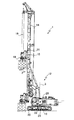
図1に、本発明に係る安全装置を備えた建設機械の構成を示す。この建設機械1は、キャリアユニット10たるクローラ型走行装置を備えた可動アースドリル機として構成されており、そのキャリアユニット10にはその建設機械の上部キャリッジ11が載っている。上部キャリッジ11は鉛直軸3周りで枢動させうるようキャリアユニット10に載せられており、その上部キャリッジ11には、マスト14を支持し上部キャリッジ11に連結するマストサポート12が載っている。マストサポート12が水平走行軸周りで可枢動な形態で設けられているため、マストサポート12を枢動させることで、上部キャリッジ11ひいてはキャリアユニット10に対するマスト14の径方向位置を調整することができる。更に、そのマスト14上には、鉛直変位可能な形態にてスレッジ15が設けられている。そのスレッジ15には、ドリルロッド19用のドリル駆動装置たる駆動ユニット18が載せられている。
FIG. 1 shows the construction of a construction machine provided with a safety device according to the present invention. The construction machine 1 is configured as a movable earth drill machine having a crawler type traveling device as a
従って、キャリアユニット10に対し上部キャリッジ11を枢動させると、駆動ユニット18もキャリアユニット10に対し鉛直軸3周りで枢動する。マストサポート12を枢動させると、駆動ユニット18がキャリアユニット10に対し枢動し鉛直軸3に対して径方向に移動する。
Therefore, when the upper carriage 11 is pivoted with respect to the
また、上部キャリッジ11上には、キャリアユニット10に対する上部キャリッジ11ひいては駆動ユニット18の枢動方向現在位置を検出する検出手段29や、上部キャリッジ11ひいてはキャリアユニット10に対する駆動ユニット18の径方向現在位置を検出する検出手段28が設けられている。後者の検出手段28は、マストサポート12の水平走行軸周り枢動角を求める回動角検出手段として構成されている。
On the upper carriage 11, detection means 29 for detecting the current position in the pivot direction of the upper carriage 11 and thus the
本発明に係る安全装置は、更に、接続先の検出手段28及び29から信号を受け取り駆動ユニット18の現在位置を調べる評価ユニット22や、建設機械1のオペレータ用キャビン内に設けられた表示手段20を備えている。評価ユニット22には、建設機械1上の他の検出手段からも信号を供給することができる。図1には、そうした検出手段の一例として、マスト14に対するスレッジ15の鉛直送りに際し作用する牽引力、押下力又はその双方を検出する検出手段31が示されている。
The safety device according to the present invention further includes an
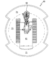
評価ユニット22及び表示手段20は、建設機械1の対傾き安定性を可視的に示すスケッチマップを作成して表示する。図2にそうしたスケッチマップの一例60を示す。このスケッチマップ60は表示手段20の画面その他に表示させることができる。
The
図2に示したスケッチマップ60は建設機械1を模式的且つ平面的に示したものであり、その上には駆動ユニット18の模式像68を含め建設機械1の模式像61が表示されている。その背景の一部を占める領域71は、安全に枢動可能な範囲を示している。この領域71は画面上に例えば緑色で表示させるとよい。オペレータがこのマップ60を見たとき、駆動ユニット18の模式像68が領域71内にあったのなら、それは、危険な傾き無しで稼働している、ということである。その逆に、模式像68が領域71外にあったとすれば、それは、傾きが危険なレベルに達しているかもしれない、ということである。
A
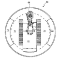
図3にスケッチマップ60の別例を示す。この図の例では二種類の可動範囲、即ち稼働制限のない第1可動範囲及び稼働制限がある第2可動範囲が画定されている。稼働制限モードでは付加的な制限、例えばメインウィンチ、補助ウィンチ、送りウィンチ等によるウィンチ牽引力に制限が課される。
FIG. 3 shows another example of the
このスケッチマップ60では、第1可動範囲が領域71、第2可動範囲が領域72で表示されている。こうした場合、領域71を例えば緑色、領域72を例えば黄色で表示させるのが望ましい。オペレータは、駆動ユニット18の模式像68が領域71の範囲内にあるのかそれとも領域72の範囲内にあるのかを見分けることができ、それにより、稼働制限がないのかあるのかを知ることができる。
In this
稼働制限付の第2可動範囲に入ったことをオペレータに知らせるため、第2可動範囲への到達に応じ、そのことを示す通知窓を表示手段20で表示するようにしてもよい。その場合、牽引力許容値を示す情報窓を画面に挿入するのが望ましい。特に、その挿入先は、スケッチマップ60が示されているのと同じ画面とするのが望ましい。
In order to notify the operator that the second movable range with operation restriction has been entered, a notification window indicating that may be displayed on the display means 20 upon reaching the second movable range. In this case, it is desirable to insert an information window indicating the allowable traction force value on the screen. In particular, the insertion destination is preferably the same screen as that on which the
1 建設機械、3 鉛直軸、10 キャリアユニット、11 上部キャリッジ、12 マストサポート、14 マスト、15 スレッジ、18 駆動ユニット、19 ドリルロッド、20 表示手段、22 評価ユニット、28,29,31 検出手段、60 スケッチマップ、61,68 模式像、71,72 領域。 DESCRIPTION OF SYMBOLS 1 Construction machine, 3 Vertical axis, 10 Carrier unit, 11 Upper carriage, 12 Mast support, 14 Mast, 15 Sledge, 18 Drive unit, 19 Drill rod, 20 Display means, 22 Evaluation unit, 28, 29, 31 Detection means, 60 Sketch map, 61, 68 Schematic image, 71, 72 regions.
Claims (12)
キャリアユニットに対する駆動ユニットの現在位置を検出する1個又は複数個の検出手段と、
キャリアユニットに対する駆動ユニットの現在位置を表示する表示手段と、
建設機械の傾きに対し所与レベルの安全性を提供しつつ駆動ユニットを動かせる可動範囲を1個又は複数個の入力値に基づき1個又は複数個定める評価ユニットと、
を備え、駆動ユニットの現在位置と併せその可動範囲を表示手段で表示させる安全装置。 A safety device for a construction machine having a carrier unit and a drive unit movable relative to the carrier unit,
One or more detection means for detecting the current position of the drive unit relative to the carrier unit;
Display means for displaying the current position of the drive unit relative to the carrier unit;
An evaluation unit for determining one or a plurality of movable ranges based on one or a plurality of input values while providing a given level of safety against the inclination of the construction machine;
And a safety device for displaying the movable range together with the current position of the drive unit on the display means.
1個又は複数個の検出手段が、キャリアユニットに対する駆動ユニットの鉛直軸周りでの枢動方向現在位置を検出し、
駆動ユニットの枢動方向現在位置と併せその可動範囲を表示手段で表示させる安全装置。 The safety device according to claim 1, wherein the drive unit is used in a construction machine pivotable about a vertical axis with respect to the carrier unit.
One or a plurality of detection means detect a current position in the pivot direction around the vertical axis of the drive unit relative to the carrier unit;
A safety device that displays the movable range of the drive unit along with the current position in the pivot direction on the display means.
1個又は複数個の検出手段が、鉛直軸に対する駆動ユニットの径方向現在位置を検出し、
駆動ユニットの径方向現在位置と併せその可動範囲を表示手段で表示させる安全装置。 The safety device according to claim 2, wherein the drive unit is used in a construction machine movable in a radial direction with respect to a vertical axis.
One or a plurality of detection means detect the current position of the drive unit in the radial direction relative to the vertical axis;
A safety device that displays the movable range together with the current radial position of the drive unit on the display means.
評価ユニットが、稼働制限のない第1可動範囲及び建設機械稼働制限がある第2可動範囲を定め、
それらの可動範囲を、互いに色を違え且つ上記現在位置と併せ、表示手段で互いに同じスケッチマップ上に表示する安全装置。 The safety device according to claim 1,
The evaluation unit determines a first movable range with no operation restriction and a second movable range with a construction machine operation restriction,
A safety device that displays these movable ranges in different colors and in combination with the current position on the same sketch map by display means.
Applications Claiming Priority (2)
| Application Number | Priority Date | Filing Date | Title |
|---|---|---|---|
| EP10004085.6 | 2010-04-16 | ||
| EP10004085.6A EP2378054B1 (en) | 2010-04-16 | 2010-04-16 | Construction machine with a safety device |
Publications (2)
| Publication Number | Publication Date |
|---|---|
| JP2011226257A true JP2011226257A (en) | 2011-11-10 |
| JP5564462B2 JP5564462B2 (en) | 2014-07-30 |
Family
ID=42710507
Family Applications (1)
| Application Number | Title | Priority Date | Filing Date |
|---|---|---|---|
| JP2011085433A Expired - Fee Related JP5564462B2 (en) | 2010-04-16 | 2011-04-07 | Safety equipment for construction machinery |
Country Status (7)
| Country | Link |
|---|---|
| US (1) | US8624752B2 (en) |
| EP (1) | EP2378054B1 (en) |
| JP (1) | JP5564462B2 (en) |
| CN (1) | CN102220862B (en) |
| BR (1) | BRPI1101739A2 (en) |
| HK (1) | HK1162632A1 (en) |
| RU (1) | RU2466241C1 (en) |
Families Citing this family (5)
| Publication number | Priority date | Publication date | Assignee | Title |
|---|---|---|---|---|
| EP2672057B1 (en) | 2012-06-07 | 2017-08-16 | Sandvik Mining and Construction Oy | Dynamic working area |
| DE102015003177A1 (en) | 2015-03-12 | 2016-09-15 | Liebherr-Werk Nenzing Gmbh | Method for operating a mobile machine with ground pressure limitation |
| DE102015215666A1 (en) * | 2015-08-18 | 2017-02-23 | Robert Bosch Gmbh | Worker guidance directly on display Display of the tool |
| EP3553229A1 (en) | 2018-04-11 | 2019-10-16 | BAUER Spezialtiefbau GmbH | Excavation device and system for monitoring a construction site |
| EP3722512B1 (en) * | 2019-04-08 | 2022-06-08 | BAUER Maschinen GmbH | Excavation device and method for operating same |
Citations (6)
| Publication number | Priority date | Publication date | Assignee | Title |
|---|---|---|---|---|
| WO1990007465A1 (en) * | 1988-12-27 | 1990-07-12 | Kato Works Co., Ltd. | Safety device for cranes |
| JPH08326459A (en) * | 1995-05-30 | 1996-12-10 | Aichi Corp | Safety device of hole digging construction post car |
| JPH10273921A (en) * | 1997-01-31 | 1998-10-13 | Komatsu Ltd | Overturning prevention device of construction machine |
| JP2004308185A (en) * | 2003-04-04 | 2004-11-04 | Mitsui Miike Mach Co Ltd | Shaft sinking device |
| JP2010001613A (en) * | 2008-06-18 | 2010-01-07 | Hitachi Constr Mach Co Ltd | Safety monitoring equipment of demolition work machine |
| JP2010138657A (en) * | 2008-12-15 | 2010-06-24 | Caterpillar Japan Ltd | Disassembling work machine |
Family Cites Families (20)
| Publication number | Priority date | Publication date | Assignee | Title |
|---|---|---|---|---|
| FI801541A (en) * | 1979-05-18 | 1980-11-19 | Coles Cranes Ltd | SAW LOAD INDICATOR FOER LAST |
| US4511974A (en) * | 1981-02-04 | 1985-04-16 | Kabushiki Kaisha Toyoda Jidoshokki Seisakusho | Load condition indicating method and apparatus for forklift truck |
| SU1159991A1 (en) | 1984-12-28 | 1985-06-07 | Киевский институт автоматики им.ХХУ съезда КПСС | Apparatus for automated monitoring of power duty of metal structures of equipment of bucket-wheel excavator |
| US5730305A (en) | 1988-12-27 | 1998-03-24 | Kato Works Co., Ltd. | Crane safety apparatus |
| DE8912027U1 (en) | 1989-10-10 | 1989-11-23 | Wirth Maschinen- Und Bohrgeraete-Fabrik Gmbh, 5140 Erkelenz, De | |
| US6894621B2 (en) * | 1997-02-27 | 2005-05-17 | Jack B. Shaw | Crane safety devices and methods |
| JP2000034093A (en) | 1998-07-21 | 2000-02-02 | Kobe Steel Ltd | Slewing type working machinery and its safety working area and setting method of rated load |
| US6272413B1 (en) * | 1999-03-19 | 2001-08-07 | Kabushiki Kaisha Aichi Corporation | Safety system for boom-equipped vehicle |
| DE20011371U1 (en) | 2000-06-28 | 2000-09-14 | Bauer Spezialtiefbau | Construction equipment |
| US6343799B1 (en) * | 2000-08-01 | 2002-02-05 | Caterpillar Inc. | Tilt mechanism for work machine |
| US6637523B2 (en) * | 2000-09-22 | 2003-10-28 | The University Of Hong Kong | Drilling process monitor |
| US6985795B2 (en) * | 2001-09-21 | 2006-01-10 | Schlage Lock Company | Material handler with center of gravity monitoring system |
| RU2245294C2 (en) | 2003-04-09 | 2005-01-27 | Мамаев Камиль Мамаевич | Method of and device for moment protection of boom crane by signals from support pickups |
| RU2267458C1 (en) | 2004-04-28 | 2006-01-10 | Тульский государственный университет | System for checking load stability of mobile load-lifting machine |
| CN100357530C (en) * | 2005-05-25 | 2007-12-26 | 石午江 | Multifunctional turn digging dynamoelectric drilling machine |
| US7325634B2 (en) | 2005-06-23 | 2008-02-05 | Atlas Copco Drilling Solutions | Track-mounted drilling machine with active suspension system |
| US7734397B2 (en) * | 2005-12-28 | 2010-06-08 | Wildcat Technologies, Llc | Method and system for tracking the positioning and limiting the movement of mobile machinery and its appendages |
| DE502006000802D1 (en) * | 2006-03-01 | 2008-07-03 | Bauer Maschinen Gmbh | A construction work apparatus and method for providing a transportation state for a construction work apparatus |
| KR100934947B1 (en) * | 2007-10-02 | 2010-01-06 | 볼보 컨스트럭션 이키프먼트 홀딩 스웨덴 에이비 | Image expressing method of heavy equipment with leveling system |
| DE102007057462A1 (en) * | 2007-11-29 | 2009-06-10 | Bayer Materialscience Ag | Process for the preparation of phosgene with reduced CO emission |
-
2010
- 2010-04-16 EP EP10004085.6A patent/EP2378054B1/en not_active Revoked
-
2011
- 2011-03-25 US US13/072,460 patent/US8624752B2/en active Active
- 2011-03-28 RU RU2011111328/03A patent/RU2466241C1/en active
- 2011-04-07 JP JP2011085433A patent/JP5564462B2/en not_active Expired - Fee Related
- 2011-04-15 BR BRPI1101739-2A patent/BRPI1101739A2/en not_active IP Right Cessation
- 2011-04-15 CN CN201110095046.2A patent/CN102220862B/en active Active
-
2012
- 2012-03-23 HK HK12102941.2A patent/HK1162632A1/en not_active IP Right Cessation
Patent Citations (6)
| Publication number | Priority date | Publication date | Assignee | Title |
|---|---|---|---|---|
| WO1990007465A1 (en) * | 1988-12-27 | 1990-07-12 | Kato Works Co., Ltd. | Safety device for cranes |
| JPH08326459A (en) * | 1995-05-30 | 1996-12-10 | Aichi Corp | Safety device of hole digging construction post car |
| JPH10273921A (en) * | 1997-01-31 | 1998-10-13 | Komatsu Ltd | Overturning prevention device of construction machine |
| JP2004308185A (en) * | 2003-04-04 | 2004-11-04 | Mitsui Miike Mach Co Ltd | Shaft sinking device |
| JP2010001613A (en) * | 2008-06-18 | 2010-01-07 | Hitachi Constr Mach Co Ltd | Safety monitoring equipment of demolition work machine |
| JP2010138657A (en) * | 2008-12-15 | 2010-06-24 | Caterpillar Japan Ltd | Disassembling work machine |
Also Published As
| Publication number | Publication date |
|---|---|
| BRPI1101739A2 (en) | 2013-01-15 |
| RU2011111328A (en) | 2012-10-10 |
| US20110254694A1 (en) | 2011-10-20 |
| RU2466241C1 (en) | 2012-11-10 |
| JP5564462B2 (en) | 2014-07-30 |
| CN102220862A (en) | 2011-10-19 |
| EP2378054B1 (en) | 2019-08-28 |
| US8624752B2 (en) | 2014-01-07 |
| EP2378054A1 (en) | 2011-10-19 |
| CN102220862B (en) | 2015-05-20 |
| HK1162632A1 (en) | 2012-08-31 |
Similar Documents
| Publication | Publication Date | Title |
|---|---|---|
| JP5564462B2 (en) | Safety equipment for construction machinery | |
| JP5395109B2 (en) | Construction machine having a computer unit for determining an adjustment range and method of operating the construction machine | |
| CN106185627B (en) | Lifting hook deflection angle monitoring device, vertical hoisting monitoring device and mobile crane | |
| JP2014091632A (en) | Outrigger pad monitoring device | |
| JP6097441B1 (en) | Crane work auxiliary device | |
| JP6113342B1 (en) | Lifting position adjustment device for overhead crane | |
| CN103130098B (en) | A kind of suspension hook drift angle Universal level-metre monitoring device and hoisting crane | |
| JP2018142123A (en) | Remote control system | |
| JP4015158B2 (en) | Crane suspended load operation display device | |
| US20220219956A1 (en) | Lifting/lowering device | |
| JP5824206B2 (en) | Suspended load swivel device | |
| JP6161156B2 (en) | Turning angle test equipment | |
| JP2010247937A (en) | Counterweight structure of crawler crane | |
| JP2007254143A (en) | Hook block swing angle detector for crane | |
| CN102954912A (en) | Balance lever machine | |
| JP2016008449A (en) | Construction machine | |
| KR20150047678A (en) | Vibration reducing apparatus for radar mast | |
| JP2017194381A (en) | Inclination detector of construction machine | |
| KR20090116029A (en) | Weight detection device for cargo crane | |
| JP3795480B2 (en) | Lifting jack lifting system | |
| JP7362427B2 (en) | Construction machinery load measuring device | |
| JP2009068262A (en) | Pile driver | |
| KR102105570B1 (en) | Apparatus for controlling hoist | |
| EP3514101B1 (en) | Crane | |
| JPH10258991A (en) | Crane cargo operation display |
Legal Events
| Date | Code | Title | Description |
|---|---|---|---|
| A977 | Report on retrieval |
Free format text: JAPANESE INTERMEDIATE CODE: A971007 Effective date: 20120921 |
|
| A131 | Notification of reasons for refusal |
Free format text: JAPANESE INTERMEDIATE CODE: A131 Effective date: 20121113 |
|
| A601 | Written request for extension of time |
Free format text: JAPANESE INTERMEDIATE CODE: A601 Effective date: 20130208 |
|
| A602 | Written permission of extension of time |
Free format text: JAPANESE INTERMEDIATE CODE: A602 Effective date: 20130214 |
|
| A521 | Written amendment |
Free format text: JAPANESE INTERMEDIATE CODE: A523 Effective date: 20130312 |
|
| A131 | Notification of reasons for refusal |
Free format text: JAPANESE INTERMEDIATE CODE: A131 Effective date: 20131022 |
|
| A521 | Written amendment |
Free format text: JAPANESE INTERMEDIATE CODE: A523 Effective date: 20140108 |
|
| TRDD | Decision of grant or rejection written | ||
| A01 | Written decision to grant a patent or to grant a registration (utility model) |
Free format text: JAPANESE INTERMEDIATE CODE: A01 Effective date: 20140527 |
|
| A61 | First payment of annual fees (during grant procedure) |
Free format text: JAPANESE INTERMEDIATE CODE: A61 Effective date: 20140616 |
|
| R150 | Certificate of patent or registration of utility model |
Ref document number: 5564462 Country of ref document: JP Free format text: JAPANESE INTERMEDIATE CODE: R150 |
|
| R250 | Receipt of annual fees |
Free format text: JAPANESE INTERMEDIATE CODE: R250 |
|
| LAPS | Cancellation because of no payment of annual fees |