JP2011216632A - Wound core transformer - Google Patents
Wound core transformer Download PDFInfo
- Publication number
- JP2011216632A JP2011216632A JP2010082709A JP2010082709A JP2011216632A JP 2011216632 A JP2011216632 A JP 2011216632A JP 2010082709 A JP2010082709 A JP 2010082709A JP 2010082709 A JP2010082709 A JP 2010082709A JP 2011216632 A JP2011216632 A JP 2011216632A
- Authority
- JP
- Japan
- Prior art keywords
- winding
- iron core
- bobbin
- core transformer
- hole
- Prior art date
- Legal status (The legal status is an assumption and is not a legal conclusion. Google has not performed a legal analysis and makes no representation as to the accuracy of the status listed.)
- Granted
Links
Images


Landscapes
- Insulating Of Coils (AREA)
Abstract
【課題】 固定金具にバンド掛けして固定するタイプの変圧器であっても、鉄心から欠け等して生じた破片の流出防止を行えること
【解決手段】 アモルファス磁性合金からなる複数枚の薄帯板を積層して構成される1ターンカット方式の鉄心10と、その鉄心の直線状の脚部に装着する巻線20と、鉄心の巻線の外側に突出する湾曲部12,12′を包み込む通気性のある不織布30と、を備える。巻線は、ボビンの外周に電線を巻き付けて構成し、その電線の最内周とボビンの外周面の所定位置には、軸方向に延び、その両端が開口するバンド溝25を備える。バンド51で固定金具50に固定する場合、バンドをバンド溝内に通過させることで、不織布を破損・開封することなく鉄心を固定できる。
【選択図】 図10PROBLEM TO BE SOLVED: To prevent outflow of debris generated by chipping from an iron core even in a type of transformer which is fixed by banding to a fixing bracket. SOLUTION: A plurality of thin ribbons made of an amorphous magnetic alloy A one-turn cut type iron core 10 formed by laminating plates, a winding 20 attached to a straight leg portion of the iron core, and curved portions 12, 12 'protruding outside the winding of the iron core are wrapped. A breathable nonwoven fabric 30. The winding is formed by winding an electric wire around the outer periphery of the bobbin, and is provided with band grooves 25 extending in the axial direction and opening at both ends at predetermined positions on the innermost periphery of the electric wire and the outer peripheral surface of the bobbin. When fixing to the fixture 50 with the band 51, the iron core can be fixed without causing the nonwoven fabric to be damaged or unsealed by passing the band through the band groove.
[Selection] Figure 10
Description
本発明は、アモルファスの磁性合金を用いて構成される鉄心を備えた巻鉄心変圧器に関するものである。 The present invention relates to a wound core transformer having an iron core formed using an amorphous magnetic alloy.
配電用変圧器等に用いる変圧器鉄心の鉄心材料の一つとして、アモルファスの磁性合金がある。また、この変圧器鉄心の形態としては、複数枚の薄帯板を積層させるとともに、適宜位置で湾曲させて端部同士を接合した1ターンカット方式のものがある。係る1ターンカット方式に上記のアモルファスの磁性合金を用いる場合、1枚の磁性薄帯板の厚さは、一般的に用いられるけい素鋼帯に比べて非常に薄く、しかも、加工歪の除去及び鉄心特性向上のための磁場焼鈍を行うと、極めて脆弱となるという特性がある。そのため、例えば、巻鉄心に衝撃や振動等の外力が加わると、鉄心の一部が欠落したり破損したりすることがある。 One of the core materials for transformer cores used in power distribution transformers is amorphous magnetic alloys. In addition, as a form of the transformer core, there is a one-turn cut type in which a plurality of thin strips are stacked and curved at an appropriate position to join ends. When the above amorphous magnetic alloy is used for such a one-turn cut method, the thickness of one magnetic strip is much thinner than that of a commonly used silicon steel strip, and the processing strain is removed. In addition, when magnetic field annealing is performed to improve iron core characteristics, there is a characteristic that it becomes extremely fragile. Therefore, for example, when an external force such as impact or vibration is applied to the wound iron core, a part of the iron core may be lost or damaged.
そのため、その欠けた鉄心の一部の破片が外部に飛散しないようにするため、鉄心の積層面に絶縁紙からなる保護シートを接着したり、特許文献1に示すように、巻線を装着した状態の鉄心における露出部分をシート状の絶縁部材で袋状に包み込むようにしたりしている。 Therefore, in order to prevent some pieces of the chipped iron core from scattering to the outside, a protective sheet made of insulating paper is adhered to the laminated surface of the iron core, or windings are attached as shown in Patent Document 1. An exposed portion of the iron core in a state is wrapped in a bag shape with a sheet-like insulating member.
そして、特許文献1に開示された発明では、所定位置に形成された2つの鉄心挿入用の窓孔を持つ絶縁部材を2枚用意し、各絶縁部材を巻線の貫通孔の両開口部が臨む側面を覆うようにそれぞれ配置する。このとき、絶縁部材の窓孔を巻線の鉄心挿入孔の開口部に相対するように絶縁部材を配置する。 In the invention disclosed in Patent Document 1, two insulating members each having two iron core insertion window holes formed at predetermined positions are prepared, and both openings of the through holes of the windings are provided for each insulating member. Arrange each side to cover the facing side. At this time, the insulating member is arranged so that the window hole of the insulating member faces the opening of the core insertion hole of the winding.
次いで、U字状に形成された鉄心の両先端を、一方の絶縁部材の外側から重ね合った窓孔・開口部内に挿入するとともに、貫通孔内を貫通させ、その鉄心の両先端を巻線の反対側の開口部から突出させる。このとき鉄心の両先端は、他方の絶縁部材の窓孔内を通過して外側に突出しているので、その両先端を折り曲げて先端同士を接合する。これにより、鉄心は、リング状になり、1ターンカット方式の巻線が形成される。 Next, both ends of the U-shaped iron core are inserted into the overlapping window holes / openings from the outside of one insulating member, penetrated through the through-hole, and both ends of the iron core are wound. It protrudes from the opening on the opposite side. At this time, since both ends of the iron core pass through the window hole of the other insulating member and protrude outward, the both ends are bent to join the ends. Thereby, an iron core becomes a ring shape and a 1-turn cut type winding is formed.
この状態では、鉄心の直線状の脚部が、巻線の貫通孔内に位置し、鉄心の湾曲している部分が巻線の外側に突出する。そして、絶縁部材は、窓孔内に鉄心の脚部が貫通した状態となり、鉄心と巻線の側面との間に介在する。その後、シート状の絶縁部材の周縁を順次持ち上げて、鉄心の露出している湾曲部位を積み込むとともに、その周縁を接着テープで固定する。このように絶縁部材で包み込むことで、包み込まれた鉄心の湾曲した部位で発生した欠けなどにより生じた破片は、その中で収納されたままとなる。 In this state, the straight leg portion of the iron core is located in the through hole of the winding, and the curved portion of the iron core protrudes outside the winding. And an insulating member will be in the state which the leg part of the iron core penetrated in the window hole, and is interposed between an iron core and the side surface of a coil | winding. Thereafter, the peripheral edge of the sheet-like insulating member is sequentially lifted to load the exposed curved portion of the iron core, and the peripheral edge is fixed with an adhesive tape. By wrapping with the insulating member in this way, fragments generated due to chipping or the like generated at the curved portion of the wrapped iron core remain housed therein.
絶縁部材は、窓孔の口内縁に、シート状の絶縁部材の平面と直交方向に突出する一定幅の鍔縁を一体に形成している。これにより、最初に絶縁部材を巻線の所定位置に被せる際にその鍔縁を巻線の開口部に挿入することで絶縁部材を位置決めすることができる。よって、短時間で所望の位置に絶縁部材を置くことができる。 The insulating member is integrally formed with a flange having a constant width that protrudes in a direction orthogonal to the plane of the sheet-like insulating member at the inner edge of the window hole. Accordingly, when the insulating member is initially put on a predetermined position of the winding, the insulating member can be positioned by inserting the flange into the opening of the winding. Therefore, the insulating member can be placed at a desired position in a short time.
特許文献1の絶縁部材は、鍔縁を備えているが、位置合わせを目的としていることからも、その鍔縁の幅(突出長さ)は比較的短くなっている。そのため、その鍔縁の部分を、その全面にわたり巻線の貫通孔の内面に接着剤等で確実に接着して密着させないと、鉄心の欠け等で生じた破片が外部へ至る経路が生じてしまい、破片の外部への流出を確実に防げないという課題がある。また、係る流出防止をするためには、貫通孔内に配置される鉄心の脚部には、保護シートなどを貼り付けるなどの別の方策を採る必要が出てくる。 Although the insulating member of Patent Document 1 includes a flange, the width (projection length) of the flange is relatively short because it is intended for alignment. For this reason, if the flange portion is not securely adhered and adhered to the inner surface of the through-hole of the winding over the entire surface with an adhesive or the like, a route to the outside where fragments generated due to chipping of the iron core or the like will occur. There is a problem that it is not possible to prevent the outflow of fragments to the outside. In order to prevent such outflow, it is necessary to take another measure such as attaching a protective sheet or the like to the legs of the iron core disposed in the through hole.
また、この種の巻鉄心変圧器は、バンドなどで所定の金具等に固定することが行われるが、上記のように、確実に閉塞するために鍔縁を、その全周に渡って接着剤で貫通孔の内面に接着すると、貫通孔内にバンドを通すことができない。よって、バンド掛けするタイプの変圧器には適さない構成となる。 In addition, this type of wound core transformer is fixed to a predetermined metal fitting etc. with a band or the like. If it adheres to the inner surface of the through hole, the band cannot pass through the through hole. Therefore, the configuration is not suitable for a banding type transformer.
上述した課題を解決するために、本発明に係る巻鉄心変圧器は、(1)アモルファス磁性合金からなる複数枚の薄帯板を積層して構成される1ターンカット方式の鉄心と、その鉄心の直線状の脚部に装着する巻線と、前記鉄心の前記巻線の外側に突出する部位を包み込む通気性のある繊維部材と、を備える。そして、前記繊維部材は、前記脚部を挿入する前記巻線の貫通孔に対向する仮想領域に形成された複数の切込線で分割された突片を有し、それら突片を前記貫通孔内に挿入配置する。さらに、前記巻線は、ボビンの外周に導電体を巻き付けて構成されるとともに、その導電体の最内周と前記ボビンの外周面の所定位置には、軸方向に延び、その両端が開口するバンド溝を備えるようにした。繊維部材は、実施形態では、不織布30に対応する。また、導電体は、実施形態の電線24に対応する。
In order to solve the above-described problems, a wound core transformer according to the present invention includes (1) a one-turn cut type iron core configured by laminating a plurality of thin ribbon plates made of an amorphous magnetic alloy, and the iron core. And a fiber member having air permeability that wraps around a portion of the iron core that protrudes outside the winding. And the said fiber member has the projecting piece divided | segmented by the several cut line formed in the virtual area facing the through-hole of the said coil | winding which inserts the said leg part, These projecting pieces are the said through-hole. Insert and place in. Further, the winding is configured by winding a conductor around the outer periphery of the bobbin, and extends in the axial direction at predetermined positions on the innermost periphery of the conductor and the outer peripheral surface of the bobbin, and both ends thereof are open. A band groove was provided. The fiber member corresponds to the
通気性(透過性)のある繊維であるので、この巻鉄心変圧器を絶縁油タイプの変圧器として製造する場合に、真空引き時に被覆内部まで絶縁油を浸透させることができ、絶縁的に良くない気泡の除去を効果的に行える。さらに、この巻鉄心変圧器をバンドにて所定の金具等に固定する場合、そのバンドをバンド溝内に挿入することで、繊維部材の外側でバンド掛けを行うことができる。よって、繊維部材が開封されず、閉塞した空間を確保できるので、鉄心から欠け等した破片の流出防止を効果的にする。さらに、突片は、仮想領域の全面を用いて構成されるので、その面積は大きく、貫通孔内に折り込まれて挿入された各突片は、適度な長さ・面積で貫通孔の内周面の開口付近を覆うことができ、貫通孔内から巻線の外部に至る経路を確実に遮断することができる。この場合に、必ずしも接着剤などを用いて全面で密着させることなく、係る遮断の効果が発揮する。 Since this is a fiber with permeability (permeability), when manufacturing this wound core transformer as an insulating oil type transformer, the insulating oil can penetrate into the inside of the coating when evacuating, so that the insulation is good. Effective air bubble removal. Furthermore, when this wound core transformer is fixed to a predetermined metal fitting or the like with a band, the band can be hung outside the fiber member by inserting the band into the band groove. Therefore, since the fiber member is not opened and a closed space can be secured, it is possible to effectively prevent the outflow of broken pieces from the iron core. Further, since the projecting piece is configured using the entire surface of the virtual region, the area of the projecting piece is large, and each projecting piece inserted into the through hole is inserted into the through hole with an appropriate length and area. The vicinity of the opening of the surface can be covered, and the path from the inside of the through hole to the outside of the winding can be reliably blocked. In this case, the blocking effect is exhibited without necessarily using an adhesive or the like to bring the entire surface into close contact.
(2)前記仮想領域は、矩形状であり、前記切込み線は、矩形状の2つの長辺と平行で中心線上に延びる第1切込線と、その第1切込線の両端と矩形状の各頂点とを結ぶ第2切込線S2を備えるとよい。このようにすると、長辺に連結された突片は台形状になり、短辺に連結された突片は三角形状となるとともに、両者の高さが同じになる。台形状の突片にすることで、長辺のほぼ全体にわたり、効率よく外部へ至る経路を閉塞することができる。 (2) The virtual region has a rectangular shape, and the cut line includes a first cut line that extends parallel to two long sides of the rectangular shape and extends on the center line, and both ends of the first cut line and a rectangular shape. It is good to provide the 2nd cut line S2 which ties each vertex. If it does in this way, the projection piece connected with the long side becomes trapezoid shape, and the projection piece connected with the short side becomes a triangle shape, and both height becomes the same. By using a trapezoidal projecting piece, the path to the outside can be efficiently blocked over almost the entire long side.
(3)前記バンド溝は、前記ボビンの外側に、軸方向に延びるように平行に複数のガイド部材を配置し、隣接するガイド部材間の空間に構成されるようにできる。このようにすると、簡単な構成で、バンド溝を形成できる。 (3) The band groove may be configured in a space between adjacent guide members by arranging a plurality of guide members in parallel so as to extend in the axial direction outside the bobbin. In this way, the band groove can be formed with a simple configuration.
(4)前記複数のガイド部材は、平板部により一体に連結されるようにするとよい。この場合、平板部と、ガイド部材は、別部材で形成したものを連結して一体化しても良いし、樹脂成形その他の方法で最初から一体成型したものでもよい。平板部は、実施形態の平板に対応する。そして、この平板部は、ボビン側に位置させても良いし、ボビンと反対側、すなわち、ガイド部材をボビン側に位置させるようにしてもよい。このようにすると、組み立てが容易に行える。 (4) The plurality of guide members may be integrally connected by a flat plate portion. In this case, the flat plate portion and the guide member may be integrated by connecting those formed by separate members, or may be integrally formed from the beginning by resin molding or other methods. The flat plate portion corresponds to the flat plate of the embodiment. The flat plate portion may be positioned on the bobbin side, or the opposite side of the bobbin, that is, the guide member may be positioned on the bobbin side. In this way, assembly can be performed easily.
(5)前記突片は、接着部材で前記ボビンに固定されるとよい。接着部材は、実施形態では接着テープに対応する。簡単に止めることができるとともに、接着剤のように塗布したり、接着剤が乾くのを待つ必要が無く、短時間で処理できる。 (5) The protrusion may be fixed to the bobbin with an adhesive member. The adhesive member corresponds to an adhesive tape in the embodiment. In addition to being able to stop easily, there is no need to apply like an adhesive or wait for the adhesive to dry, and it can be processed in a short time.
所定の固定金具等にバンド掛けして固定するタイプや、絶縁油内に含浸させるタイプの変圧器であっても、鉄心から欠け等して生じた破片の流出防止を行うことができる。 Even if the transformer is of a type that is banded and fixed on a predetermined fixing bracket or the like, or is a type of transformer that is impregnated in insulating oil, it is possible to prevent outflow of fragments generated due to chipping from the iron core.
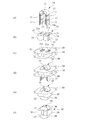
図1は、本発明に係る巻鉄心変圧器の好適な一実施形態並びにその製造工程を示している。図1(a)は、本実施形態の巻鉄心変圧器の構成要素の一つである鉄心10を示しており、図1(b)は、本実施形態の巻鉄心変圧器の構成要素の一つである巻線20を示している。
FIG. 1 shows a preferred embodiment of a wound core transformer according to the present invention and a manufacturing process thereof. Fig.1 (a) has shown the
鉄心10は、所定のアモルファスの磁性合金からなる複数枚の薄帯板を積層させるとともに、適宜位置で湾曲させてU字状に形成したものであり、2本の直線状の脚部11と、それを繋ぐ湾曲部12を有する。脚部11の先端13は、図1(e),(f)に示すように、最終的に折り曲げられるとともに接合されて他方の湾曲部12′を構成する。これにより、1ターンカット方式の鉄心となる。また、積層状態の複数枚の薄帯板がバラバラにならないように、脚部11の所定位置に固定テープ15を巻き付けて固定している。また、積層された複数の薄帯板が露出する側面が、積層面10aとなる。この鉄心10の材質並びに構成は、従来のものと同様であるので、その詳細な説明を省略する。
The
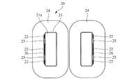
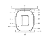
巻線20は、筒状の絶縁体からなるボビン21の周囲に対し、絶縁皮膜を施した電線24を巻き付けて構成されるが、このとき、一対のボビン21の非対向側の外側面に軸方向に延びる複数本(ここでは3本)の直方体状の絶縁体からガイド板22を平行に配置し、電線24はそのガイド板22の外側を巻き付けるようにしている。これにより、図2に拡大して示すように、ガイド板22を配置したボビン21の外周面側に位置する電線24は、ガイド板22の外面に接するように巻かれることから、隣接するガイド板22間の空間には電線24が入り込むことはなく、巻き付けられた電線24の最内周と、ガイド板22とボビン21の外周面で囲まれた空隙が形成される。そして、その空隙は、軸方向に貫通し、後述するバンド溝25を構成する。そして巻線20は、ボビン21の内周面側の空間が軸方向両端で開口した貫通孔21aとなり、その貫通孔21aに、鉄心10の直線状の脚部11が挿入される。
The winding 20 is configured by winding an
また、ガイド板22は、本実施形態では、3本の帯板部材から構成しているが、これらは、係る3つの帯板部材をそれぞれ別々に用意して、ボビン21の外周面に配置しても良いが、3つに分離した帯板部材を用いた場合には、それぞれのガイド板22を適切な位置関係にするためにボビン21に接着等して固定するのが好ましい。また、そのように別々の部材を設けるのではなく、一枚の薄く広い平板の上に予め所定の相対位置関係になるように3つのガイド板22を固定して一体化しておき、それをボビン21の外周面に沿わすと共に、電線24を巻きつけるようにすれば、特に、ガイド板22(それを取り付けた平板)と、ボビン21とを固定する必要はない。さらに、図3に拡大して示すように、ガイド板22を取り付ける平板26を、ボビン21の外側に位置させ、取り付け状態では、ボビン21と平板26でガイド板22を挟み込むようにしても良い。そのようにすると、電線24を巻き付ける前に、ガイド溝25が形成され、電線24は、平板26の周りに巻き付けることになり、ガイド溝25内に電線24が入り込むのが確実に抑制できる。
Further, in this embodiment, the
そして、不織布貼り付け工程を実行する。すなわち、図1(c)に示すように、巻線20の軸方向両端を覆うように、通気性の良好な繊維部材である不織布20を配置する。この不織布20は、図4(a)に示すように、略矩形状のシート本体の4隅を凹状に切除した切欠部31を備え、さらに、巻線20の貫通孔21aに対向する仮想矩形状領域Rに、各頂点から内側に延びる所定パターンの切込線S1,S2が形成されている。本実施形態では、仮想矩形状領域Rは、巻線20の貫通孔21aの形状に符合して長方形となっているので、その長方形の2つの長辺と平行で中心線上に延びる第1切込線S1と、その第1切込線S1の両端と仮想矩形状領域Rの各頂点とを結ぶ第2切込線S2を備えている。これにより、仮想矩形状領域Rの内部は、その仮想矩形状領域Rの長辺と、第1切込線S1と、それらの両端同士を繋ぐ第2切込線S2により区画される等脚台形状の2つの第1突片32と、仮想矩形状領域Rの短辺と、その短辺の両端の頂点から延びる第2切込線S2により区画される三角形状の2つの第2突片33の、4つの突片に分割される。そして、第1突片32は、仮想矩形状領域Rの長辺に連結され、その長辺を基点して折り曲げることができる。また、第2突片33は、仮想矩形状領域Rの短辺に連結され、その短辺を基点として折り曲げることができる。もちろん、不織布であるので、突片32,33の任意の位置で折り曲げることもできる。また、本実施形態では、第1突片32の高さ(長辺と第1切込線S1間の間隔)h1と、第2突片33の高さ(短辺から対向する頂点までの長さ)h2は、同じ長さとしている。
And a nonwoven fabric sticking process is performed. That is, as shown in FIG.1 (c), the
そして、係る不織布20を用い、図1(c)並びに図4に拡大して示すように、仮想矩形状領域Rが巻線20の貫通孔21aに対応するように配置すると共に、各切込線S1,S2により分割された4つの突片32,34をそれぞれの基点(基端)となる仮想矩形状領域Rの長辺,短辺を基準に内側に折り曲げ、貫通孔21a内に挿入配置させる。これにより、仮想矩形状領域Rの部分が開口されて、開口部30aとなる。この開口部30aにより、巻線20の貫通孔21aの両端が開放される。
And using this
また、突片32,33は、仮想矩形状領域Rに所定パターンの切込線S1,S2を形成して構成されるので、仮想矩形状領域Rの全体を無駄なく利用して構成され、各突片32,33の面積・高さh1,h2も大きくとれる。よって、貫通孔21a内に挿入配置される突片32,33の長さ(面積)も大きくなる。そして、上述したように、第1突片32の高さh1と、第2突片33の高さh2は、同じ長さとしているので、各突片32,33内に挿入された深さは等しくなる。そして、各突片32,33の先端を、接着テープ38を用いて巻線20のボビン21の内周面に固定する。
Further, since the projecting
なお、ワニスその他の樹脂や接着剤などで各突片32,33をボビン21の内周面に接着一体化しても良いが、接着テープ38を用いる方法の方が、簡単かつ短時間で行えるので好ましい。なお、接着テープ38の配置位置並びに個数は任意である。また、この第1突片32を等脚台形状としたため、長辺のほぼ全長に渡り、高さh1の状態を維持することができる。また、三角形状の第2突片33の高さh2は、第1突片32の高さh1と一致させたことにより、第2突片33が必要以上に長く、反対側の開口部側にまで延びることはない。
The protruding
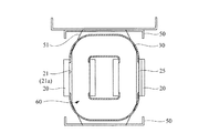
次いで、鉄心挿入工程に移行する。すなわち、図1(a)に示すU字状の鉄心10を用い、その先端13から貫通孔21a内に挿入し、脚部11が、貫通孔21a内を貫通するようにする(図1(d),図6参照)。すると、この脚部11の先端13は、挿入側と反対側の巻線20の外側に突出する。そして、脚部11は、不織布30の孔部30a内も貫通する。また、鉄心10の先端13は、巻線20の貫通孔21aの一方の開口側(図では上方)から挿入し、貫通孔21a内を進み、他方の開口側(図では下方)から外部に突出するが、このとき、係る出口側の他方の開口側に配置した不織布30の突片32,33の先端は、貫通孔21aの内部に向かって延びるように配置されており、その配置方向は、鉄心10の先端13の進行方向と逆向きとなっている。そのため、突片32,33の先端が、鉄心10の先端13に接触して、開口側に押し戻される力が働くこともあるが、突片32,33の高さh1,h2を同じにしたことで片方の突片の高さが極端に高くて貫通孔21aの奥深くまで位置することはない。よって、係る押し戻される力が働いてもその時間は短く、突片23,33を止めた接着テープ38が剥がれて、突片32,33が外側に押し戻される事態の発生を抑制できる。
Next, the process proceeds to the iron core insertion process. That is, the
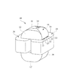
その後、その突出した鉄心10の先端13を互いに折り曲げて、その端部同士を接合することで、他方の湾曲部12′が構成され、1ターンカット方式の鉄心が形成される。そして、展開状態の不織布30を用いて、鉄心10の巻線20の外側に露出している湾曲部12,12′を包み込むとともに、その不織布30の端部を接着テープ39で固定する(図1(e),(f),図7参照)。これにより、本発明に係る巻鉄心変圧器の一実施形態のものが製造できる。図の例では、最初に、接合した湾曲部12′側を包み込み(図1(e))、その後に、別の湾曲部12側を包み込む(図1(f))ようにしたが、その順番は任意であり、最初に湾曲部12側を包み込んでももちろん良い。
Thereafter, the leading ends 13 of the protruding
すなわち、本発明に係る巻鉄心変圧器の好適な一実施形態は、アモルファス磁性合金からなる複数枚の薄帯板を積層して構成される1ターンカット方式の鉄心10と、その鉄心10の直線状の脚部11に装着する巻線20と、その鉄心の巻線20の外側に突出する部位を包み込む不織布30と、を備える。不織布30には、巻線20の貫通孔21aに対向する位置に、適宜の第1,第2切込線S1,S2で分割された第1,第2突片32,33を有し、それら両突片32,33を、貫通孔21a内に挿入するとともに、接着テープ38で固定する。このように突片32,33を貫通孔21aに折り込むことで、不織布30も開口部が形成され、鉄心10の脚部11は、巻線20の貫通孔21aとともに不織布30の開口部にも挿入する。
That is, a preferred embodiment of the wound core transformer according to the present invention is a one-turn cut
さらに、巻線20は、ボビン21の外周に電線24を巻き付けて構成するが、電線24の最内周とボビン21の外周面の所定位置には、軸方向に延びるバンド溝25を設ける。このバンド溝25は、直方体状の複数のガイド板22を軸方向に延びるように平行に配置することで、隣接するガイド板22の間の空間により形成する。
Further, the winding 20 is configured by winding the
そして、このように不織布30で湾曲部12,12′を包み込むことで、本発明に係る一実施形態の巻鉄心変圧器は、図7に示すように、ガイド板22の端部が露出し、バンド溝25も軸方向に貫通した状態となる。また、不織布30にて湾曲部12,12′を包み込むことで、仮に湾曲部12,12′を構成するアモルファスの帯板に欠け等が生じて、鉄心10から破片が離脱したとしても、包み込まれた不織布30内に収まり外部に飛散することはない。また、巻線20の貫通孔21a内に挿入された鉄心10の直線状の脚部11は、直接不織布30その他の保護シートで覆われていないので、鉄心10から欠けた破片が積層面10aから離脱するおそれがあるが、その場合でも、不織布30の各突片32,33が、巻線20の貫通孔21aの内周面に貼り付けられているので、巻線20のボビン21(貫通孔21a)と一対の不織布30による閉空間が構成されるため、やはり、外部に離散することはない。さらに、本実施形態では、突片32,33は接着テープ38で固定しているだけであるため、接着剤で固定するのと相違し、その全面でしっかりとボビン21の内周面に密着して完全なる閉空間を構成はしていない。しかし、突片32,33の長さ・面積をある程度大きく確保できたことから、突片32,33とボビン21内周面との間に形成された隙間を通って破片が外部に流出することは阻止できる。
And, by wrapping the
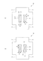
このようにして露出された部分が不織布30で包み込まれた巻線20付の鉄心10からなる巻鉄心変圧器60は、例えば、絶縁油タイプのものに適用する場合、まず、図8に示すように、固定金具50に設置され、バンド51に固定される。このとき、バンド51は、バンド溝25内を通過させることで、鉄心10の周囲に沿わし、確実に固定できる。しかも、不織布30で包み込まれた内部空間は、そのまま維持されるので、上述した通り、仮に鉄心10に欠けが生じても、外部に飛散してくることはない。
When the
これに対し、バンド溝を設けないと、図9に示すように、不織布30を巻線20のボビン21の内周面に接着すると、貫通孔21aが不織布30により閉塞されるため、そのままでは、バンド51を貫通孔21a内に通すことができない。そのため、図示するように、バンド51を不織布30の一部に貫通させることになる。すると、その貫通により開封された不織布30の部位から、破片が外部に排出される可能性があり、不織布30で包み込んだ効果が低下してしまう。
On the other hand, if the band groove is not provided, as shown in FIG. 9, when the
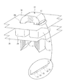
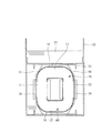
そして、図8に示すようにバンド掛けして固定した鉄心10等を、図10に示すように、固定金具50ごと変圧器ケース52内に収納するとともに内部に絶縁油53を充填する。すると、本実施形態では、不織布30は、通気性が良好であるので、真空引き時に被覆内部まで絶縁油が浸透し、絶縁的に良くない気泡の除去を効果的に行うことができる。
Then, as shown in FIG. 8, the
また、不織布30に形成する切込線は、上述したものに限ることはなく、例えば、図4(b)に示すように、仮想矩形状領域Rの対角線に配置する第3切込線S3とすることもできる。このようにすると、X字状の切込線となり、仮想矩形状領域Rの長辺に連結された第3突片36と、短辺に連結された第4突片37は、ともに三角形状となり、第3突片36の高さh3は第1突片32の高さh1と同じであるが、第4突片37の高さh4は、第2突片33の高さh2に比べると高くなる。この場合、第3切込線S3のパターンはX字状となり、簡単に形成できるが、第4突片37の高さh4が高いことで、貫通孔21aの奥まで入り込むことになる。その結果、上述した実施形態に比べると、鉄心10の先端13により押し戻される可能性が出てくる。さらに、第3突片36が三角形となるので、端に行くほど突出量が短くなるので、仮想矩形状領域Rの頂点付近では、突片の存在量が少なく、鉄心10から欠けた破片が外部に至る経路が構成され易くなる。それらのことから鑑み、図4(b)のものでも実用に供し得るものの、図4(a)に示す不織布30の形態の方がより好ましいといえる。
Moreover, the score line formed in the
10 鉄心
20 巻線
21 ボビン
21a 貫通孔
22 ガイド板
25 バンド溝
26 平板
30 不織布(通気性のある繊維部材)
32 第1突片
33 第2突片
38 接着テープ
35 ガイド溝
50 固定金具
51 バンド
53 絶縁油
60 巻鉄心変圧器
DESCRIPTION OF
32
Claims (5)
その鉄心の直線状の脚部に装着する巻線と、
前記鉄心の前記巻線の外側に突出する部位を包み込む通気性のある繊維部材と、
を備え、
前記繊維部材は、前記脚部を挿入する前記巻線の貫通孔に対向する仮想領域に形成された複数の切込線で分割された突片を有し、それら突片を前記貫通孔内に挿入配置し、
前記巻線は、ボビンの外周に導電体を巻き付けて構成されるとともに、その導電体の最内周と前記ボビンの外周面の所定位置には、軸方向に延び、その両端が開口するバンド溝を備えたことを特徴とする巻鉄心変圧器。 A one-turn cut type iron core constructed by laminating a plurality of thin ribbon plates made of an amorphous magnetic alloy;
Windings to be attached to the straight legs of the iron core,
A breathable fiber member that wraps around a portion of the iron core that protrudes outside the winding;
With
The fiber member has projecting pieces divided by a plurality of cut lines formed in a virtual region facing the through hole of the winding into which the leg is inserted, and the projecting pieces are placed in the through hole. Insert and place
The winding is configured by winding a conductor around the outer periphery of the bobbin, and is a band groove extending in the axial direction at a predetermined position on the innermost periphery of the conductor and the outer peripheral surface of the bobbin and having both ends open. A wound core transformer characterized by comprising:
前記切込み線は、矩形状の2つの長辺と平行で中心線上に延びる第1切込線と、その第1切込線の両端と矩形状の各頂点とを結ぶ第2切込線S2を備えたことを特徴とする請求項1に記載の巻鉄心変圧器。 The virtual area is rectangular,
The incision line includes a first incision line parallel to two long sides of the rectangular shape and extending on the center line, and a second incision line S2 connecting both ends of the first incision line and each vertex of the rectangular shape. The wound core transformer according to claim 1, further comprising a wound core transformer.
Priority Applications (1)
| Application Number | Priority Date | Filing Date | Title |
|---|---|---|---|
| JP2010082709A JP5686428B2 (en) | 2010-03-31 | 2010-03-31 | Winding core transformer |
Applications Claiming Priority (1)
| Application Number | Priority Date | Filing Date | Title |
|---|---|---|---|
| JP2010082709A JP5686428B2 (en) | 2010-03-31 | 2010-03-31 | Winding core transformer |
Publications (2)
| Publication Number | Publication Date |
|---|---|
| JP2011216632A true JP2011216632A (en) | 2011-10-27 |
| JP5686428B2 JP5686428B2 (en) | 2015-03-18 |
Family
ID=44946087
Family Applications (1)
| Application Number | Title | Priority Date | Filing Date |
|---|---|---|---|
| JP2010082709A Active JP5686428B2 (en) | 2010-03-31 | 2010-03-31 | Winding core transformer |
Country Status (1)
| Country | Link |
|---|---|
| JP (1) | JP5686428B2 (en) |
Citations (5)
| Publication number | Priority date | Publication date | Assignee | Title |
|---|---|---|---|---|
| JPS5773914U (en) * | 1980-10-24 | 1982-05-07 | ||
| JPH03120014U (en) * | 1990-03-23 | 1991-12-10 | ||
| JPH04299812A (en) * | 1991-03-28 | 1992-10-23 | Aichi Electric Co Ltd | Manufacture of static induction electric equipment |
| JP2002164222A (en) * | 2000-11-28 | 2002-06-07 | Hitachi Ltd | Amorphous transformer |
| JP2009021281A (en) * | 2007-07-10 | 2009-01-29 | Hitachi Industrial Equipment Systems Co Ltd | Winding core type static inductor |
-
2010
- 2010-03-31 JP JP2010082709A patent/JP5686428B2/en active Active
Patent Citations (5)
| Publication number | Priority date | Publication date | Assignee | Title |
|---|---|---|---|---|
| JPS5773914U (en) * | 1980-10-24 | 1982-05-07 | ||
| JPH03120014U (en) * | 1990-03-23 | 1991-12-10 | ||
| JPH04299812A (en) * | 1991-03-28 | 1992-10-23 | Aichi Electric Co Ltd | Manufacture of static induction electric equipment |
| JP2002164222A (en) * | 2000-11-28 | 2002-06-07 | Hitachi Ltd | Amorphous transformer |
| JP2009021281A (en) * | 2007-07-10 | 2009-01-29 | Hitachi Industrial Equipment Systems Co Ltd | Winding core type static inductor |
Also Published As
| Publication number | Publication date |
|---|---|
| JP5686428B2 (en) | 2015-03-18 |
Similar Documents
| Publication | Publication Date | Title |
|---|---|---|
| JP4973420B2 (en) | Stator manufacturing method | |
| JPH04212403A (en) | Magnetic core sheet | |
| KR20170007264A (en) | Core case unit, coil component, and method for producing coil component | |
| KR880003352A (en) | Magnetic core manufacturing method | |
| WO2009072227A1 (en) | Transformer | |
| JPH02266504A (en) | Stationary induction electric apparatus and manufacture thereof | |
| JP2011103751A (en) | Insulation structure of concentrated winding motor | |
| JP5686428B2 (en) | Winding core transformer | |
| WO2019123797A1 (en) | Hybrid core transformer | |
| JP3387433B2 (en) | Inductance components | |
| JP6466728B2 (en) | Transformer and manufacturing method thereof | |
| JP5114679B2 (en) | Reactor | |
| JP2010062279A (en) | Shell type amorphous transformer | |
| JP3197588U (en) | Winding iron core of transformer | |
| JP6084499B2 (en) | Amorphous winding core transformer | |
| JP6153900B2 (en) | Reactor | |
| JP2894959B2 (en) | Wound core transformer and method of manufacturing the same | |
| JP3436162B2 (en) | Line filter | |
| JP4725455B2 (en) | Motor core parts | |
| CN214124977U (en) | Miniature armature winding assembly | |
| JP2005159380A (en) | Amorphous iron core transformer and manufacturing method thereof | |
| KR102136271B1 (en) | Method for manufacturing core for transformer and core for transformer manufactured thereby | |
| JP3349411B2 (en) | Amorphous iron core transformer | |
| JP3412309B2 (en) | Electromagnetic device | |
| JP2010050272A (en) | Coil device |
Legal Events
| Date | Code | Title | Description |
|---|---|---|---|
| A621 | Written request for application examination |
Free format text: JAPANESE INTERMEDIATE CODE: A621 Effective date: 20130308 |
|
| A977 | Report on retrieval |
Free format text: JAPANESE INTERMEDIATE CODE: A971007 Effective date: 20131227 |
|
| A131 | Notification of reasons for refusal |
Free format text: JAPANESE INTERMEDIATE CODE: A131 Effective date: 20140213 |
|
| A521 | Request for written amendment filed |
Free format text: JAPANESE INTERMEDIATE CODE: A523 Effective date: 20140319 |
|
| A711 | Notification of change in applicant |
Free format text: JAPANESE INTERMEDIATE CODE: A712 Effective date: 20140620 |
|
| A131 | Notification of reasons for refusal |
Free format text: JAPANESE INTERMEDIATE CODE: A131 Effective date: 20141113 |
|
| A521 | Request for written amendment filed |
Free format text: JAPANESE INTERMEDIATE CODE: A523 Effective date: 20141226 |
|
| TRDD | Decision of grant or rejection written | ||
| A01 | Written decision to grant a patent or to grant a registration (utility model) |
Free format text: JAPANESE INTERMEDIATE CODE: A01 Effective date: 20150114 |
|
| A61 | First payment of annual fees (during grant procedure) |
Free format text: JAPANESE INTERMEDIATE CODE: A61 Effective date: 20150116 |
|
| R150 | Certificate of patent or registration of utility model |
Ref document number: 5686428 Country of ref document: JP Free format text: JAPANESE INTERMEDIATE CODE: R150 |
|
| R250 | Receipt of annual fees |
Free format text: JAPANESE INTERMEDIATE CODE: R250 |
|
| R250 | Receipt of annual fees |
Free format text: JAPANESE INTERMEDIATE CODE: R250 |