JP2011198060A - Hardware and software cooperation filtering processing system - Google Patents
Hardware and software cooperation filtering processing system Download PDFInfo
- Publication number
- JP2011198060A JP2011198060A JP2010064341A JP2010064341A JP2011198060A JP 2011198060 A JP2011198060 A JP 2011198060A JP 2010064341 A JP2010064341 A JP 2010064341A JP 2010064341 A JP2010064341 A JP 2010064341A JP 2011198060 A JP2011198060 A JP 2011198060A
- Authority
- JP
- Japan
- Prior art keywords
- hardware
- software
- unit
- processing unit
- actuator
- Prior art date
- Legal status (The legal status is an assumption and is not a legal conclusion. Google has not performed a legal analysis and makes no representation as to the accuracy of the status listed.)
- Pending
Links
Images

Classifications
-
- G—PHYSICS
- G06—COMPUTING OR CALCULATING; COUNTING
- G06F—ELECTRIC DIGITAL DATA PROCESSING
- G06F9/00—Arrangements for program control, e.g. control units
- G06F9/06—Arrangements for program control, e.g. control units using stored programs, i.e. using an internal store of processing equipment to receive or retain programs
- G06F9/46—Multiprogramming arrangements
- G06F9/50—Allocation of resources, e.g. of the central processing unit [CPU]
- G06F9/5005—Allocation of resources, e.g. of the central processing unit [CPU] to service a request
- G06F9/5027—Allocation of resources, e.g. of the central processing unit [CPU] to service a request the resource being a machine, e.g. CPUs, Servers, Terminals
Landscapes
- Engineering & Computer Science (AREA)
- Software Systems (AREA)
- Theoretical Computer Science (AREA)
- Physics & Mathematics (AREA)
- General Engineering & Computer Science (AREA)
- General Physics & Mathematics (AREA)
- Programmable Controllers (AREA)
Abstract
【課題】サービスの記述であるモジュールと、そこで利用されるセンサ・アクチュエータへアクセスするモジュールが分離する。
【解決手段】本発明のハードソフト連携フィルタリング処理システムは、センサとアクチュエータが接続されたハード部とネットワークに接続されたソフト部とを有するハードソフト連携フィルタリング処理システムにおいて、ソフト部またはハード部による動作を決定する処理を、ハード部に接続されたセンサからの入力情報を処理する入力処理部と、ソフト部で初期設定されたデータに基づいてアクチュエータの動作を決定するサービス処理部と、アクチュエータを操作するデータを作成する出力処理部とに分割する。
【選択図】図1A module which is a description of a service and a module which accesses a sensor / actuator used therein are separated.
The hardware / software cooperative filtering processing system according to the present invention is a hardware / software cooperative filtering processing system having a hardware part to which a sensor and an actuator are connected and a software part connected to a network. The input processing unit that processes input information from the sensor connected to the hardware unit, the service processing unit that determines the operation of the actuator based on the data initially set by the software unit, and the operation of the actuator The data is divided into an output processing unit that creates data to be processed.
[Selection] Figure 1
Description
本発明は、インターネットなどのネットワークで利用されるネットワーク機器システムに関し、特にセンサやアクチュエータ等の監視システムや制御システムに接続され動作する技術に関する。 The present invention relates to a network device system used in a network such as the Internet, and more particularly to a technology that operates by being connected to a monitoring system or a control system such as a sensor or an actuator.
実世界からの情報を収集して処理を実行し、ユーザへのサービスを提供する実世界情報処理システムは、サービス提供者が所有する情報機器により構成されてきた。しかし、サーバなどの情報機器を管理するコストがサービス提供者の大きな負担となっており、最近では、サービス提供者の情報機器に代わりユーザへのサービスをネットワーク越しに提供するクラウドシステムが登場している。クラウドシステムにおいては、実世界からの情報は、データセンタまで伝達され、データセンタにて蓄積、処理されることによって高度意味情報の抽出が実施され、実世界に結果がフィードバックされる。データセンタに至るネットワークにおいて多くのネットワーク機器を通過するため、フィードバックが行われるまでに少なくとも数秒オーダーの処理遅延が発生する。そのため、リアルタイム性を要求するサービス(プラント制御、金融アルゴリズム取引、予防保全など)においては、信頼性を確保しつつ、処理遅延を短縮することが課題となる。また、今後はセンサが様々な分野で普及し、実世界からの情報量が急増すると予測される。このため、情報量増加に伴う消費電力の急増を最小限に抑止することが大きな課題となる。 A real-world information processing system that collects information from the real world, executes processing, and provides services to users has been configured by information devices owned by service providers. However, the cost of managing information devices such as servers has become a major burden on service providers, and recently, cloud systems that provide services to users over the network in place of service provider information devices have appeared. Yes. In the cloud system, information from the real world is transmitted to the data center, where high-level semantic information is extracted by being stored and processed in the data center, and the result is fed back to the real world. Since many network devices pass through the network that reaches the data center, a processing delay of at least several seconds occurs before feedback is performed. Therefore, in a service that requires real-time properties (plant control, financial algorithm transaction, preventive maintenance, etc.), it becomes a problem to reduce processing delay while ensuring reliability. In the future, sensors are expected to spread in various fields, and the amount of information from the real world is expected to increase rapidly. For this reason, it becomes a big subject to suppress the rapid increase of the power consumption accompanying the increase in information amount to the minimum.
FPGA(Field Programmable Gate Array)で実現されているハードウェアモジュールと、CPUで実行されるソフトウェアモジュールのどちらで実行するかを選択でき、そのモジュールを転送速度で選択できる情報処理システムが特許文献1に開示されている。
上記方法ではサービスの記述であるモジュールと、そこで利用されるセンサ・アクチュエータへアクセスするモジュールが分離できず、モジュールが要求するデータのサイズが大きいときにソフトウェア動作させたい場合等、呼び出されるセンサ・アクチュエータへのアクセス方法を変更する場合、同様な機能を持つセンサ・アクチュエータへの変更が難しく、モジュール自体の変更が必要になり、モジュールの管理が面倒になる。 In the above method, the module that is the description of the service and the module that accesses the sensor / actuator used there cannot be separated, and the sensor / actuator that is called when you want to operate the software when the data size required by the module is large When the access method is changed, it is difficult to change to a sensor / actuator having the same function, and the module itself needs to be changed, which makes the management of the module troublesome.
本発明のハードソフト連携フィルタリング処理システムは、センサとアクチュエータが接続されたハード部とネットワークに接続されたソフト部とを有するハードソフト連携フィルタリング処理システムにおいて、ソフト部またはハード部による動作を決定する処理を、ハード部に接続されたセンサからの入力情報を処理する入力処理部と、ソフト部で初期設定されたデータに基づいてアクチュエータの動作を決定するサービス処理部と、アクチュエータを操作するデータを作成する出力処理部とに分割する。 The hardware / software cooperative filtering processing system of the present invention is a hardware / software cooperative filtering processing system having a hardware part to which a sensor and an actuator are connected and a software part connected to a network. Creates an input processing unit that processes input information from sensors connected to the hardware unit, a service processing unit that determines the operation of the actuator based on the data initially set by the software unit, and data for operating the actuator The output processing unit is divided.
本発明の他の態様は、各処理部をネットワーク機器のハード部・ソフト部のどちらにでも設置できるようにする。 According to another aspect of the present invention, each processing unit can be installed in either a hardware unit or a software unit of a network device.
本発明のさらに他の態様は、複数のセンサ・アクチュエータをまとめて一つのセンサ・アクチュエータとして扱えるようにする。 According to still another aspect of the present invention, a plurality of sensors / actuators can be collectively handled as one sensor / actuator.
本発明のさらに他の態様は、上位のノードからまたは自ネットワーク機器の負荷状態に合わせて、入出力処理の方法を変更できるようにする。 According to still another aspect of the present invention, an input / output processing method can be changed from an upper node or in accordance with a load state of a local network device.
本発明によれば、モジュールと、センサのデータの取り出し、アクチュエータの駆動を行う機能を分離することにより、センサ・アクチュエータの変更があってもモジュールの変更が不要することができ、モジュールの可用性を向上できる。 According to the present invention, by separating the module and the function of taking out sensor data and driving the actuator, it is possible to eliminate the need to change the module even if the sensor / actuator is changed. It can be improved.
本発明の実施形態を、実施例1〜4により以下に説明する。 Embodiments of the present invention will be described below by Examples 1-4.
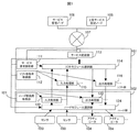
図1は、本実施例のハードソフト連携フィルタリング処理システム構成を示すブロック図である。本実施例のハードソフト連携フィルタリング処理システムは、一つまたは複数の、ネットワーク機器ソフト部101、ソフト部101にPCIなどの規格で接続されたネットワーク機器ハード部102、ハード部102にPCI、Ethernet(登録商標)、USB(Universal Serial Bus)、DIO(Digital I/O)等の規格で接続されたセンサ103、アクチュエータ104でネットワーク機器が構成され、ネットワーク107でソフト部102と接続された上位サービス記述ノード105、サービス管理ノード106を備える。
FIG. 1 is a block diagram illustrating a hardware / software cooperative filtering processing system configuration according to the present embodiment. The hardware / software cooperative filtering processing system according to the present embodiment includes one or a plurality of network
上位サービス記述ノード105、サービス管理ノード106の間のネットワーク107は、IPプロトコルなどに従う通信パケットが転送される一般的な通信路であり、インターネットやイントラネット、あるいはそれらの複合的な通信ネットワークである。
A
ソフト部101とハード部102では、センサ103からの情報をハードモジュール選択部124でソフト部101かハード部102のどちらで解析を行うかを決定し、決定されたソフト部101に置かれた入力処理部115またはハード部102に置かれた入力処理部122で情報を解析する。ソフトモジュール選択部114でどの入力処理部からの分析の結果なのかを確認しながら受け、サービス記述部113に渡す。サービス記述部113は、その分析結果を基にサービスの動作内容を決定する。ソフトモジュール選択部114でその動作内容を、ソフト部101の出力処理部116またはハード部102の出力処理部123のどちらで実行させるかを決定する。ソフト部101の出力処理部116またはハード部の出力処理部123で実際にアクチュエータ104を動かすためのデータを作成し、ハードモジュール選択部124でどちらの出力処理部でどの出力処理部の結果なのかを確認しながら受け、目的のアクチュエータ104へデータを渡し、アクチュエータ104を起動させることでサービス記述部113の内容を動作させる。また、サービス記述部113は、ネットワーク107を経由し上位サービス記述ノード105へ情報を送付・再度受信を行い他ネットワーク機器と協調動作を行うこともできる。
In the
図2では、図1に示す、ソフトモジュール選択部114とハードモジュール選択部124、サービス要求解析部111、ソフト部負荷取得部112、ハード部負荷取得部121の動作と構成について記述する。サービス要求解析部111は、サービス記述部113が保持し、各サービス内容を記述したサービス記述テーブル204に書かれた各サービス記述に合わせた要求レベルをサービス管理ノード106から取得し、その要求レベルをソフトモジュール選択部114とハードモジュール選択部124に入力し、ソフト部101の入力処理部115かハード部102の入力処理部122のどちらを利用するか、またソフト部101の出力処理部116かハード部102の出力処理部123のどちらを利用するかを決定する。
2 describes the operation and configuration of the software
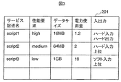
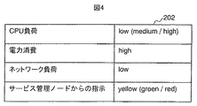
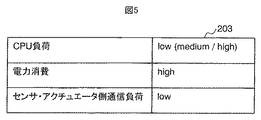
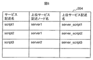
図3はサービス要求テーブル201の構成について、図4はソフト部負荷テーブル202の構成、図5はハード部負荷テーブル203の構成、図6は、サービス記述テーブル204の構成について記述する。 3 describes the configuration of the service request table 201, FIG. 4 describes the configuration of the software load table 202, FIG. 5 describes the configuration of the hardware load table 203, and FIG. 6 describes the configuration of the service description table 204.
図3に示すサービス要求テーブル201は、サービス記述名、性能要求、データサイズ、電力使用量、および、入出力種別の項目を有する。図4に示すソフト部負荷テーブル202は、CPU負荷、電力消費、ネットワーク負荷、サービス管理ノードからの指示などのソフト部101の負荷に関する項目を有する。図5に示すハード部負荷テーブル203は、CPU負荷、電力消費、センサ・アクチュエータ側通信負荷などのハード部102の負荷に関する項目を有する。図6に示すサービス記述テーブル204は、サービス記述名、上位サービス記述ノード名、および、上位サービス記述名の項目を有する。
The service request table 201 shown in FIG. 3 includes items of service description name, performance request, data size, power consumption, and input / output type. The software part load table 202 shown in FIG. 4 includes items related to the load of the
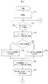
図7Aは、ハードソフト連携フィルタリング処理システムで実行される処理のフローチャートである。まず、サービス管理ノード106または直接管理者より、ソフト部101内部のサービス記述テーブル204に対し、サービス記述名、上位サービス記述ノード名、当システムを呼び出す場合の上位サービス記述名を登録するとともに、サービス記述の本体である、スクリプトまたはバイナリ実行プログラムをソフト部102に設置する。また、サービス要求テーブル201を、サービス管理ノード106または直接管理者により設定し、どのサービス記述がソフト部の入力処理部115で実行されるのか、ハード部の入力処理部122で実行されるのかを、センサ種別毎に決定する(701)。次に、各サービス記述に必要なセンサ103からのデータを待つ(702)。データを受信したら、ハードモジュール選択部124に送付され(703)、ステップ701でセンサ種別毎に決定された、ソフト部101内の入力処理部115またはハード部102内の入力処理部122にてデータの分析を行う(704)。ここでの分析では、複数のセンサから得られた同一時刻のデータの平均値演算処理や、単一のセンサから得られた一定時間範囲のデータの平均値演算処理、複数のセンサから得られた同一時刻のデータの最大値/最小値演算処理、単一のセンサから得られた一定時間範囲のデータの最大値/最小値演算処理、閾値を用いたセンサデータの異常値判定処理、センサデータの微分値、積分値などを用いた異常値判定処理、高速フーリエ変換によるセンサデータの周波数成分の演算処理、センシング情報の時間方向のサンプル間引き処理、センシング情報の量子化処理(ビット数削減、倍精度から整数などのデータ形式変換を含む)、複数のセンシング情報のまとめパケット生成処理(3種類の情報をセットで32bit化するなど)、ヘッダ情報の圧縮処理(例:IETF規格RFC4944(6lowPAN-HC-04)に規定)、カメラ画像情報のフレーム間引き処理、カメラ画像情報の画像サイズ変更処理、カメラ画像情報の顔検出、動き検出などの特徴抽出処理等を含む(705,706)。次にその分析結果をソフトモジュール選択部114に送付し(707)、その結果を用いて目的のサービス記述を実行する(708)。
FIG. 7A is a flowchart of processing executed by the hardware / software cooperative filtering processing system. First, the
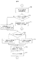
図7Bで続きを説明する。サービス記述部113にて、実行された各サービス記述の結果を作成し(709)、上位サービス記述ノードに結果を戻すかどうかをサービス記述自体で確認し(710)、戻す場合、処理結果を上位サービス記述ノード105に送付して(711)、センサからのデータ待ちに戻る。サービス記述にて上位サービス記述ノード105に戻るのではなく、アクチュエータ104を起動する記述であった場合、処理結果をソフトモジュール選択部114に送付する(712)。そこで、ハード部102の出力処理部123またはソフト部101の出力処理部116のどちらを実行するのかをサービス要求テーブル201を確認して決定する(713)。ハード部102の出力処理部123またはソフト部101の出力処理部116で、目的のアクチュエータを起動するためのデータを、サービス記述の処理結果を元に作成し(714、715)、ハードモジュール選択部124に送付する(716)。アクチュエータ104にデータを送付しアクチュエータ104を起動する(717)。その後、センサ103の入力待ちに戻る。以上により、センサ104の情報を使ってサービス記述を実行し、上位サービス記述ノード105へ戻るまたはアクチュエータ104を起動することが可能になる。
The continuation will be described with reference to FIG. 7B. The
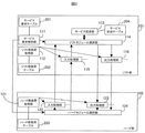
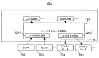
図8は、本実施例のハードソフト連携フィルタリング処理システム構成を示すブロック図である。入力冗長処理部1241では、複数のセンサの入力を確認して、一部のデータを取得できない場合にも一定の時間でデータを入力処理部115、122へ戻す。これにより、一部のセンサの故障などでデータがすべて取得できない場合にも、目的のサービス記述を実行し、上位サービス記述ノード105へ戻るまたはアクチュエータ104を起動することが可能になる。また、出力冗長処理部1242において、複数アクチュエータから動作可能なアクチュエータを選んで動作させることで、アクチュエータの一部が故障した場合にも、目的のアクチュエータの動作を実行することが可能になる。
FIG. 8 is a block diagram illustrating a hardware / software cooperative filtering processing system configuration according to this embodiment. The input
(ソフトハード選択)
図9を用いて、サービス要求テーブル201の作成方法を説明する。実施例1における図2のサービス要求解析部111で利用するサービス要求テーブル201に、サービス管理ノードで管理しているサービス記述で要求された、性能、必要なデータサイズ、電力使用量の値を設定する。次に、サービス要求テーブル201の各項目を読み出し(901)、性能要求が大きく(High)で、データサイズが小さい項目から優先して、ハード部で利用できるメモリ量または電力使用量を超えない範囲で(902、903、904)、ハード部の入出力部122、123を割り当て(905、907)、また、残りをソフト部の入出力部115、116で実行するように設定する(906、907)。以上をサービス要求テーブル201の各項目で繰り返す(908)。以上により、外部機器に実現されたハード部の入力処理部・出力処理部と、ソフト部の入力処理部・出力処理部のどちらを利用するかを、サービス記述で必要とされるデータサイズ・性能・電力使用量により決められるパラメータを用いて選択することを実現することが可能になる。
(Soft hardware selection)
A method for creating the service request table 201 will be described with reference to FIG. The service request table 201 used in the service
(パラメータによる動作変更)
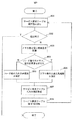
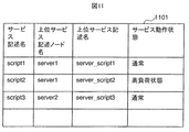
図2のソフト部負荷取得部112・ハード部負荷取得部121の動作を図10で説明する。まずセンサからデータが入力されるかまたはサービス記述部においてサービス記述が動作することで、入力処理部または出力処理部が起動する(1001)。ここで、各入出力処理部で負荷状態を取得する設定が入っている場合(1002)、ハード部負荷取得部121またはソフト部負荷取得部112が、ハード部負荷テーブル203またはソフト部負荷テーブル202に負荷状態を設定する(1003)。各入出力処理部の設定により、ソフト部ではCPU負荷、電力消費、ネットワーク負荷、サービス管理ノードからの指示等のパラメータを用いて、またハード部ではCPU負荷、電力消費、センサ・アクチュエータ側通信負荷等を用いて、通常の入出力処理を行うか、高負荷時における間引き運転処理を行うかを選択する(1004、1005、1006)。次に、上位サービス記述ノードへ、このシステムでどのような動作を行ったかを、入力処理後の分析データに付加する(1007)。付加したデータは、図11の上位サービス記述ノード宛データテーブル1101に示す。以上により、各処理部が置かれる外部機器または計算機の負荷状態や消費電力、計算機のネットワークに接続された、他の計算機からの指示に基づいて処理内容を変更することが可能になる。
(Operation change by parameter)
The operations of the software part
以上の実施形態によれば、モジュールと、センサのデータの取り出し、アクチュエータの駆動を行う機能を分離することにより、センサ・アクチュエータの変更があってもモジュールの変更が不要することができ、モジュールの可用性を向上できる。また、センサ・アクチュエータをまとめて操作できるため、グループ内のセンサ・アクチュエータが故障で停止しても、残ったセンサ・アクチュエータで動作を継続することができる。また、センサへのアクセス機能に負荷情報を与えることで、高負荷時にも停止せず、限定された機能の提供を行うことができる。モジュールが要求するセンサ・アクチュエータへのアクセスに必要な情報のデータサイズに合わせて、データサイズが制限されているFPGA等のハードウェア上のアクセス機能を利用するか、PC等のソフトウェア上のそれを利用するか決定できることで、できるだけ多くの機能を機器上に実現できる。 According to the above embodiment, by separating the module and the function of taking out the sensor data and driving the actuator, it is possible to eliminate the need to change the module even if the sensor / actuator is changed. Improve availability. Further, since the sensors / actuators can be operated collectively, even if the sensors / actuators in the group are stopped due to a failure, the operation can be continued with the remaining sensors / actuators. Further, by providing load information to the access function to the sensor, it is possible to provide a limited function without stopping even when the load is high. Use the access function on the hardware such as FPGA with limited data size according to the data size of the information required for accessing the sensor / actuator required by the module, or use it on the software such as PC. By deciding whether to use, as many functions as possible can be realized on the device.
101:ソフト部、102:ハード部、103:センサ、104:アクチュエータ、105:上位サービス記述ノード、106:サービス管理ノード、107:ネットワーク、111:サービス要求解析部、112:ソフト部負荷取得部、113:サービス記述部、114:ソフトモジュール選択部、115:入力処理部(ソフト部)、116:出力処理部(ソフト部)、121:ハード部負荷取得部、122:入力処理部(ハード部)、123:出力処理部(ハード部)、124:ハードモジュール選択部、1241:入力冗長処理部、1242:出力助長処理部、201:サービス要求テーブル、202:ソフト部負荷テーブル、203:ハード部負荷テーブル、204:サービス記述テーブル、1101:上位サービス記述ノード宛データテーブル。 101: Software part, 102: Hardware part, 103: Sensor, 104: Actuator, 105: Host service description node, 106: Service management node, 107: Network, 111: Service request analysis part, 112: Software part load acquisition part, 113: Service description section, 114: Software module selection section, 115: Input processing section (software section), 116: Output processing section (software section), 121: Hardware section load acquisition section, 122: Input processing section (hardware section) , 123: output processing unit (hardware unit), 124: hardware module selection unit, 1241: input redundancy processing unit, 1242: output promotion processing unit, 201: service request table, 202: software unit load table, 203: hardware unit load Table, 204: service description table, 1101: data table addressed to upper service description node .
Claims (4)
前記ソフト部または前記ハード部による動作を決定する処理を、前記ハード部に接続された前記センサからの入力情報を処理する入力処理部と、前記ソフト部で初期設定されたデータに基づいて前記アクチュエータの動作を決定するサービス処理部と、前記アクチュエータを操作するデータを作成する出力処理部とに分割することを特徴とするハードソフト連携フィルタリング処理システム。 In a hardware / software collaborative filtering processing system having a hardware section to which a sensor and an actuator are connected and a software section connected to a network,
The process of determining the operation by the software part or the hardware part, the input processing part for processing input information from the sensor connected to the hardware part, and the actuator based on the data initially set by the software part A hardware / software collaborative filtering processing system, characterized in that the system is divided into a service processing unit for determining the operation of the actuator and an output processing unit for creating data for operating the actuator.
Priority Applications (2)
| Application Number | Priority Date | Filing Date | Title |
|---|---|---|---|
| JP2010064341A JP2011198060A (en) | 2010-03-19 | 2010-03-19 | Hardware and software cooperation filtering processing system |
| US13/051,990 US20110227720A1 (en) | 2010-03-19 | 2011-03-18 | Cooperated filtering with real time and non-real time system |
Applications Claiming Priority (1)
| Application Number | Priority Date | Filing Date | Title |
|---|---|---|---|
| JP2010064341A JP2011198060A (en) | 2010-03-19 | 2010-03-19 | Hardware and software cooperation filtering processing system |
Publications (1)
| Publication Number | Publication Date |
|---|---|
| JP2011198060A true JP2011198060A (en) | 2011-10-06 |
Family
ID=44646763
Family Applications (1)
| Application Number | Title | Priority Date | Filing Date |
|---|---|---|---|
| JP2010064341A Pending JP2011198060A (en) | 2010-03-19 | 2010-03-19 | Hardware and software cooperation filtering processing system |
Country Status (2)
| Country | Link |
|---|---|
| US (1) | US20110227720A1 (en) |
| JP (1) | JP2011198060A (en) |
Families Citing this family (2)
| Publication number | Priority date | Publication date | Assignee | Title |
|---|---|---|---|---|
| US9773026B1 (en) * | 2012-12-20 | 2017-09-26 | EMC IP Holding Company LLC | Calculation of system utilization |
| JP6721832B2 (en) * | 2016-08-24 | 2020-07-15 | 富士通株式会社 | Data conversion program, data conversion device, and data conversion method |
Citations (1)
| Publication number | Priority date | Publication date | Assignee | Title |
|---|---|---|---|---|
| JP3738802B2 (en) * | 1998-02-10 | 2006-01-25 | 富士ゼロックス株式会社 | Information processing system |
Family Cites Families (6)
| Publication number | Priority date | Publication date | Assignee | Title |
|---|---|---|---|---|
| JPH11147335A (en) * | 1997-11-18 | 1999-06-02 | Fuji Xerox Co Ltd | Plot process apparatus |
| US8781609B2 (en) * | 2006-05-19 | 2014-07-15 | Siemens Industry, Inc. | Signal processing network |
| US7368918B2 (en) * | 2006-07-27 | 2008-05-06 | Siemens Energy & Automation | Devices, systems, and methods for adaptive RF sensing in arc fault detection |
| US7974793B2 (en) * | 2007-08-31 | 2011-07-05 | Siemens Industry, Inc. | Systems, and/or devices to control the synchronization of diagnostic cycles and data conversion for redundant I/O applications |
| US7786919B2 (en) * | 2007-09-21 | 2010-08-31 | Siemens Industry, Inc. | Systems and/or devices for providing an isolated analog output or analog input |
| JP4898932B2 (en) * | 2010-02-15 | 2012-03-21 | 株式会社日立製作所 | Network node, information processing system and method |
-
2010
- 2010-03-19 JP JP2010064341A patent/JP2011198060A/en active Pending
-
2011
- 2011-03-18 US US13/051,990 patent/US20110227720A1/en not_active Abandoned
Patent Citations (1)
| Publication number | Priority date | Publication date | Assignee | Title |
|---|---|---|---|---|
| JP3738802B2 (en) * | 1998-02-10 | 2006-01-25 | 富士ゼロックス株式会社 | Information processing system |
Also Published As
| Publication number | Publication date |
|---|---|
| US20110227720A1 (en) | 2011-09-22 |
Similar Documents
| Publication | Publication Date | Title |
|---|---|---|
| CN116346948B (en) | Multi-protocol conversion method and system based on micro-service | |
| US10747592B2 (en) | Router management by an event stream processing cluster manager | |
| CN100474257C (en) | Method and apparatus for off-load processing of a message stream | |
| CN111131379B (en) | A distributed traffic collection system and edge computing method | |
| US10432704B2 (en) | Translation of messages using sensor-specific and unified protocols | |
| CN112104754B (en) | Network proxy method, system, device, equipment and storage medium | |
| JP6258562B2 (en) | Relay device, network monitoring system, and program | |
| CN102571947B (en) | A method, device and system for agent processing data | |
| US11368410B2 (en) | System and method for scaling analytics collection | |
| CN113014573B (en) | Monitoring method, system, electronic device and storage medium of DNS (Domain name Server) | |
| RU2605918C2 (en) | Method for providing functions in industrial automation system and industrial automation system | |
| US20210064419A1 (en) | Task based service management platform | |
| CN103368872A (en) | Data packet forwarding system and method | |
| US6868437B1 (en) | System and method for interprocess communication of remote procedure call messages utilizing shared memory | |
| JP2011198060A (en) | Hardware and software cooperation filtering processing system | |
| CN104363275B (en) | A kind of methods, devices and systems for acting on behalf of processing data | |
| CN113872814A (en) | Information processing method, device and system for content distribution network | |
| CN108289041A (en) | A kind of processing method and relevant apparatus of server info | |
| CN115022389B (en) | Full-link information processing method, system, electronic device and storage medium | |
| CN114697340B (en) | A registration scheduling method for multi-device access and related products | |
| CN115994156A (en) | Method and system for real-time analysis of data streams | |
| CN114520808B (en) | Request processing method, device, electronic device and computer readable storage medium | |
| CN118509390A (en) | Data processing method, device, storage medium and electronic equipment | |
| CN102301652A (en) | Message switching | |
| CN111240867B (en) | Information communication system and method |
Legal Events
| Date | Code | Title | Description |
|---|---|---|---|
| A621 | Written request for application examination |
Free format text: JAPANESE INTERMEDIATE CODE: A621 Effective date: 20120910 |
|
| A977 | Report on retrieval |
Free format text: JAPANESE INTERMEDIATE CODE: A971007 Effective date: 20130807 |
|
| A131 | Notification of reasons for refusal |
Free format text: JAPANESE INTERMEDIATE CODE: A131 Effective date: 20130820 |
|
| A02 | Decision of refusal |
Free format text: JAPANESE INTERMEDIATE CODE: A02 Effective date: 20131217 |