JP2011193065A - Imaging equipment - Google Patents
Imaging equipment Download PDFInfo
- Publication number
- JP2011193065A JP2011193065A JP2010055253A JP2010055253A JP2011193065A JP 2011193065 A JP2011193065 A JP 2011193065A JP 2010055253 A JP2010055253 A JP 2010055253A JP 2010055253 A JP2010055253 A JP 2010055253A JP 2011193065 A JP2011193065 A JP 2011193065A
- Authority
- JP
- Japan
- Prior art keywords
- exposure
- field
- flicker
- shutter speed
- image
- Prior art date
- Legal status (The legal status is an assumption and is not a legal conclusion. Google has not performed a legal analysis and makes no representation as to the accuracy of the status listed.)
- Pending
Links
Images


Classifications
-
- G—PHYSICS
- G03—PHOTOGRAPHY; CINEMATOGRAPHY; ANALOGOUS TECHNIQUES USING WAVES OTHER THAN OPTICAL WAVES; ELECTROGRAPHY; HOLOGRAPHY
- G03B—APPARATUS OR ARRANGEMENTS FOR TAKING PHOTOGRAPHS OR FOR PROJECTING OR VIEWING THEM; APPARATUS OR ARRANGEMENTS EMPLOYING ANALOGOUS TECHNIQUES USING WAVES OTHER THAN OPTICAL WAVES; ACCESSORIES THEREFOR
- G03B7/00—Control of exposure by setting shutters, diaphragms or filters, separately or conjointly
- G03B7/08—Control effected solely on the basis of the response, to the intensity of the light received by the camera, of a built-in light-sensitive device
- G03B7/091—Digital circuits
- G03B7/093—Digital circuits for control of exposure time
-
- H—ELECTRICITY
- H04—ELECTRIC COMMUNICATION TECHNIQUE
- H04N—PICTORIAL COMMUNICATION, e.g. TELEVISION
- H04N23/00—Cameras or camera modules comprising electronic image sensors; Control thereof
- H04N23/70—Circuitry for compensating brightness variation in the scene
- H04N23/71—Circuitry for evaluating the brightness variation
-
- H—ELECTRICITY
- H04—ELECTRIC COMMUNICATION TECHNIQUE
- H04N—PICTORIAL COMMUNICATION, e.g. TELEVISION
- H04N23/00—Cameras or camera modules comprising electronic image sensors; Control thereof
- H04N23/70—Circuitry for compensating brightness variation in the scene
- H04N23/745—Detection of flicker frequency or suppression of flicker wherein the flicker is caused by illumination, e.g. due to fluorescent tube illumination or pulsed LED illumination
-
- H—ELECTRICITY
- H04—ELECTRIC COMMUNICATION TECHNIQUE
- H04N—PICTORIAL COMMUNICATION, e.g. TELEVISION
- H04N25/00—Circuitry of solid-state image sensors [SSIS]; Control thereof
- H04N25/50—Control of the SSIS exposure
- H04N25/53—Control of the integration time
-
- H—ELECTRICITY
- H04—ELECTRIC COMMUNICATION TECHNIQUE
- H04N—PICTORIAL COMMUNICATION, e.g. TELEVISION
- H04N25/00—Circuitry of solid-state image sensors [SSIS]; Control thereof
- H04N25/70—SSIS architectures; Circuits associated therewith
- H04N25/71—Charge-coupled device [CCD] sensors; Charge-transfer registers specially adapted for CCD sensors
- H04N25/73—Charge-coupled device [CCD] sensors; Charge-transfer registers specially adapted for CCD sensors using interline transfer [IT]
Abstract
Description
本発明は、周期的発光光源によるフリッカの除去を行う撮像装置およびその制御方法に関する。 The present invention relates to an imaging apparatus that performs flicker removal using a periodic light source and a control method thereof.
光学画像を電気信号に変換する撮像素子として、例えばCCDセンサなどの固体撮像素子が民間製品や監視向け製品などのカメラ製品に広く用いられている。これらカメラ製品は、絞り、電子シャッタを用いる撮像素子のシャッタ速度、AGC(Automatic Gain Control)、NDフィルタ等による露光制御を行っており、所定の露光目標値に到達させるように自動露光制御(Auto Exposure Control:以下AEと略す)を行って、一定の露光量を得るようにしている。撮像素子にCCDセンサを用いる場合は電荷蓄積量を制御することになる。 As an image sensor that converts an optical image into an electrical signal, for example, a solid-state image sensor such as a CCD sensor is widely used in camera products such as commercial products and surveillance products. These camera products perform exposure control using an aperture, shutter speed of an image sensor using an electronic shutter, AGC (Automatic Gain Control), ND filter, etc., and automatic exposure control (Auto Exposure Control (hereinafter abbreviated as AE) is performed to obtain a constant exposure amount. When a CCD sensor is used as the image sensor, the charge accumulation amount is controlled.
上記AEは、上述した絞り、シャッタ速度(シャッタ開放時間)、AGCゲイン制御のうちどの方法を選択するかをカメラの照度レベルに応じて決定するプログラムAEを用いている。プログラムAEにはシャッタ速度固定プログラムAE、絞り固定プログラムAEなど様々な種類があり、撮影シーンや環境によって使い分けている。 The AE uses a program AE that determines which method to select among the above-described aperture, shutter speed (shutter opening time), and AGC gain control according to the illuminance level of the camera. There are various types of program AEs, such as a shutter speed fixing program AE and an aperture fixing program AE, which are properly used depending on the shooting scene and environment.
プログラムAEでは、非インバータ方式の蛍光灯やLED照明など商用電源周波数に依存して光量が周期的に変動する光源を用いたシーン撮影時に、商用電源周期と一コマのカメラ画像を出力する1フィールドの周期が異なるとフィールド間の電荷蓄積量に差が生じ画像のちらつきであるフリッカが発生することから、フリッカの除去処理は必須技術である。 In Program AE, one field that outputs a commercial power cycle and one frame of camera image when shooting a scene using a light source whose light intensity varies periodically depending on the commercial power frequency, such as non-inverter fluorescent lamps and LED lighting. If the period is different, there is a difference in the amount of accumulated charges between the fields, and flicker that is flickering of the image occurs. Therefore, flicker removal processing is an essential technique.
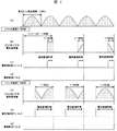
図1に周期100[Hz]で電荷蓄積量が周期的に変動する蛍光灯フリッカについて示す。(a)の光源発光周期に示す様に、商用交流電源周波数50[Hz]使用時の非インバータ方式の蛍光灯(以後蛍光灯と略す)では電源周波数50[Hz]の2倍である100[Hz]の周期で蛍光灯の発光量が変化している。 FIG. 1 shows a fluorescent lamp flicker whose charge accumulation amount periodically fluctuates at a cycle of 100 [Hz]. As shown in the light source light emission cycle of (a), a non-inverter type fluorescent lamp (hereinafter abbreviated as a fluorescent lamp) when using a commercial AC power supply frequency of 50 [Hz] is 100 [ The amount of light emitted from the fluorescent lamp changes at a frequency of [Hz].
(b)は発光周期100[Hz]の蛍光灯を、テレビ放送方式のNTSC規格である毎秒60フレームの画像を出力するビデオカメラでシャッタ速度1/180[秒]に設定した時の各フィールドにおけるCCDセンサの電荷蓄積量を示す。(c)はCCDの電荷掃き捨てパルスによる電荷の蓄積開始タイミング、(d)がCCDの電荷転送パルスによる電荷の蓄積終了タイミングを示す。発光量が変わると、(b)の様に同一被写体に対しても各フィールド間でCCDセンサの電荷蓄積量が異なってしまい、この差がフリッカを発生させ記録した画像を劣化させてしまう。 (b) shows a fluorescent lamp with a light emission cycle of 100 [Hz] in each field when the shutter speed is set to 1/180 [second] with a video camera that outputs an image of 60 frames per second, which is the NTSC standard of the television broadcasting system. Indicates the amount of charge stored in the CCD sensor. (c) shows the charge accumulation start timing by the CCD charge sweep pulse, and (d) shows the charge accumulation end timing by the CCD charge transfer pulse. When the light emission amount changes, the charge accumulation amount of the CCD sensor differs between fields even for the same subject as shown in (b), and this difference generates flicker and deteriorates the recorded image.
これは商用交流電源の周波数をT[Hz]とした時にn/2T[秒](nは自然数:n = 1,2,3…)にシャッタ速度を固定して除去できることが知られている。すなわち(e)に示すように発光周期100[Hz]の蛍光灯で(f)の蓄積開始と(g)の蓄積終了タイミングでシャッタ速度を光源発光周期と同じ1/100[秒]に固定すれば、各フレームで同じ電荷蓄積量を確保することができフリッカは発生しなくなる。従来、蛍光灯フリッカに対して商用交流電源の周波数がT[Hz]である時、n/2T[秒]にシャッタ速度に固定することはフリッカを発生させなくすることができる有効な手段であった(逆にシャッタ速度n/100[秒]以外であれば、フィールド間で電荷蓄積量に差が生じフリッカが発生する)。 It is known that the shutter speed is fixed at n / 2T [seconds] (n is a natural number: n = 1, 2, 3,...) When the frequency of the commercial AC power supply is T [Hz]. That is, as shown in (e), the shutter speed is fixed to 1/100 [second], which is the same as the light source emission period, at the start of accumulation of (f) and the accumulation end timing of (g) with a fluorescent lamp with a light emission period of 100 [Hz]. For example, the same charge accumulation amount can be secured in each frame, and flicker does not occur. Conventionally, when the frequency of the commercial AC power supply is T [Hz] with respect to the fluorescent lamp flicker, fixing the shutter speed to n / 2T [seconds] is an effective means for preventing the occurrence of flicker. (Conversely, if the shutter speed is not n / 100 [seconds], there is a difference in the amount of accumulated charge between fields, and flicker occurs).
また、近年需要の増加した商用交流電源により発光するLEDパネル等のLED照明を用いた場合でも、同様にカメラ画像はLED照明からのフリッカの影響を大きく受けることになる。LED照明は蛍光灯とは発光特性が違い、印加する電圧が閾値を越えると速やかに発光して点灯と消灯を繰り返して発光しており、蛍光灯より発光強度が大きい為に激しいフリッカが発生する。 In addition, even when LED lighting such as an LED panel that emits light from a commercial AC power source that has been increasing in demand in recent years is used, the camera image is also greatly affected by flicker from the LED lighting. LED lighting has different light emission characteristics from fluorescent lamps, and when the applied voltage exceeds the threshold, it emits light quickly and repeats turning on and off, and it emits intense flicker due to its higher emission intensity than fluorescent lamps. .
LED照明は近年様々な用途で幅広く活用され始めている。LEDの点灯方法には、直流点灯とパルス点灯の2種類があり、LED照明の発光は身近な商用交流電源を利用したパルス点灯で発光していることが多い。LED照明を用いた機器の一つである信号機では、信頼性を考慮して、LEDの素子点灯は単純な駆動回路構成とし、商用交流電源を全波整流した電圧を印加することで発光しており、その発光周期は非インバータ方式の蛍光灯と同じく2T[Hz]である。よって、蛍光灯フリッカの時と同じようにn/2T[秒]にシャッタ速度を固定することでフリッカを除去できる。 In recent years, LED lighting has begun to be widely used in various applications. There are two types of LED lighting methods, DC lighting and pulse lighting, and LED lighting often emits light by pulse lighting using a familiar commercial AC power supply. In a traffic light that is one of the devices that use LED lighting, LED elements are lit by a simple drive circuit configuration in consideration of reliability, and light is emitted by applying a full-wave rectified voltage from a commercial AC power supply. The light emission period is 2 T [Hz], similar to the non-inverter type fluorescent lamp. Therefore, flicker can be removed by fixing the shutter speed to n / 2T [seconds] as in the case of fluorescent lamp flicker.
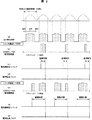
図2に周期100[Hz]で電荷蓄積量が周期的に変動するLEDフリッカについて示す。(a)は商用交流電源の周期50[Hz]に同期して発光するLEDの発光周期を示す。(b)のシャッタ速度1/180[秒]に固定しNTSC周期60[Hz]のカメラで(c)の蓄積開始と(d)の蓄積終了タイミングで電荷を蓄積した時と、(e)のシャッタ速度1/100[秒]に固定して(f)の蓄積開始と(g)の蓄積終了タイミングで電荷を蓄積したときの例を示す。 FIG. 2 shows an LED flicker whose charge accumulation amount periodically varies at a cycle of 100 [Hz]. (a) shows the light emission period of the LED which emits light in synchronization with the commercial AC power supply period 50 [Hz]. (b) The shutter speed is fixed at 1/180 [sec] and the charge is accumulated at the start of accumulation in (c) and at the end of accumulation in (d) with a camera with an NTSC cycle of 60 [Hz]. An example is shown in which the charge is accumulated at the accumulation start timing of (f) and the accumulation end timing of (g) with the shutter speed fixed at 1/100 [second].
LEDは消灯と点灯を繰り返したほぼ矩形波で発光しており、NTSC規格カメラの60[Hz]の周期では光源発光周期と同じ1/100[秒]のシャッタ速度に設定してフリッカを除去することができる。シャッタ速度1/180[秒]に設定した場合には、LEDが周期100[Hz]で点灯、消灯を繰り返して発光しているので各フィールドで蓄積している点灯部と消灯部のどの位相部を蓄積しているかが異なり、各フィールド間で電荷蓄積量が大きく異なってしまいフリッカが激しくなる。 The LED emits light with an almost rectangular wave that is repeatedly turned off and on, and the flicker is eliminated by setting the shutter speed to 1/100 [second], which is the same as the light source emission period, in the period of 60 [Hz] for NTSC standard cameras. be able to. When the shutter speed is set to 1/180 [seconds], the LED is lit and extinguished repeatedly at a cycle of 100 [Hz], so which phase part of the lit part and extinguished part accumulated in each field Therefore, the amount of charge accumulation differs greatly between the fields, and flicker becomes intense.
しかし、上記シャッタ速度固定によるフリッカ防止露光制御は、シャッタによる露光調整ができないという問題があった。この問題を解決するために、特許文献1では各カメラ周期でシャッタを略均等に所定回数設定し露光を行ってフリッカを低減させつつ、シャッタによる露光調整を可能にする方法が開示されている。更には特許文献1を改善させた特許文献2では、各カメラ周期でフリッカ周期と同じ期間内にシャッタを略均等に所定回数設定させる方法により、フリッカを確実に除去させつつ、シャッタによる露光調整を可能にする方法が開示されている。 However, the flicker prevention exposure control by fixing the shutter speed has a problem that exposure adjustment by the shutter cannot be performed. In order to solve this problem, Patent Document 1 discloses a method that enables exposure adjustment by the shutter while setting the shutter substantially uniformly a predetermined number of times in each camera cycle and performing exposure to reduce flicker. Further, in Patent Document 2, which is an improvement over Patent Document 1, exposure adjustment by the shutter is performed while reliably removing flicker by a method in which the shutter is set almost uniformly within the same period as the flicker period in each camera period. A method for enabling is disclosed.
近年の凶悪犯罪の増加からセキュリティ分野への関心が高まり、犯罪の防止や証拠の記録を目的とした撮像装置として監視カメラの需要は増加してきている。監視カメラは民生品のカメラと異なり、銀行、エレベータ、駐車場、道路、車などに固定した状態で使用されることが大半であり画像に映る1コマが大切な情報となる。 With the recent increase in violent crimes, interest in the security field has increased, and the demand for surveillance cameras as imaging devices for the purpose of crime prevention and evidence recording has increased. Unlike consumer cameras, surveillance cameras are mostly used in a fixed state on banks, elevators, parking lots, roads, cars, etc., and one frame displayed in the image is important information.
例えば、エレベータ内に設置されるエレベータカメラやエスカレータの監視用小型カメラ、また車両の走行中に起こった何らかの衝撃直前の数十秒間画像データを保存・記録し、事故の検証や分析に用いるドライブレコーダでは、構造を単純にするため絞り固定カメラが多く、シャッタとAGCのみで露光調整しなければならない。撮影した画像中には蛍光灯やLED照明等の光源による照明光を含むシーンが多く含まれており、照明光の発光周期によるフリッカが原因で画像上の必要な情報の欠落や画像劣化を招くことがあるので、フリッカ除去処理が必ず必要となる。 For example, elevator cameras installed in elevators, small cameras for monitoring escalators, and drive recorders that store and record image data for several tens of seconds just before any impact that occurs during vehicle travel, and are used for accident verification and analysis Then, in order to simplify the structure, there are many fixed-aperture cameras, and exposure adjustments must be made using only the shutter and AGC. The captured image contains many scenes that include illumination light from a light source such as a fluorescent lamp or LED lighting, causing flickering due to the emission cycle of the illumination light, leading to missing required information on the image and image degradation Therefore, flicker removal processing is always necessary.
この監視カメラにおけるフリッカの解決手段として、特許文献1や特許文献2に示された各カメラ周期でシャッタを略均等に所定回数設定する露光制御により、フリッカを低減または除去しつつシャッタで露光調整可能にするという方法は、手法として各カメラ周期で複数回露光し各露光量を加算するため、動きのある被写体に対しては通常シャッタ速度制御に比べて残像やブレを発生させてしまうという問題があった。監視カメラにおいてはフリッカを低減または除去することが重要であると共に、画像の一つ一つが重要な情報となるため、動きのある被写体に対しても残像やブレを発生させず劣化のない情報を入手できることが望ましい。 As a means of resolving flicker in this surveillance camera, exposure can be adjusted with the shutter while reducing or eliminating flicker by exposure control that sets the shutter approximately a predetermined number of times in each camera cycle shown in Patent Document 1 and Patent Document 2. In the method, the exposure is performed a plurality of times in each camera period and each exposure amount is added, so that there is a problem that an afterimage or blur is generated for a moving subject as compared with the normal shutter speed control. there were. In a surveillance camera, it is important to reduce or eliminate flicker, and since each image is important information, information that does not deteriorate without causing afterimages and blurring even for moving subjects. It should be available.
本発明は、画像出力単位である固有のフィールド周期を持つ撮像装置を用いて、特定周期で発光する光源によりCCDセンサで記録を行う撮像装置の露光制御方法において、前記CCDセンサの露光制御のためのシャッタ速度制御に、露光開始時の電荷掃き捨てパルスと、露光終了時の電荷読み出しパルスの印加タイミングを各フィールドで可変させ、露光期間をフィールド内でシフトさせる露光期間シフト量によるシャッタ速度制御を行い、各フィールドにおいて前記光源発光周期の同位相部を前記CCDセンサで露光してフリッカを除去することを特徴とする。 The present invention relates to an exposure control method for an image pickup apparatus that performs recording with a CCD sensor using a light source that emits light at a specific period using an image pickup apparatus having a specific field period that is an image output unit. Shutter speed control based on the exposure period shift amount that shifts the exposure period within the field by varying the application timing of the charge sweep-out pulse at the start of exposure and the charge readout pulse at the end of exposure in each field. And, in each field, the same phase portion of the light source emission period is exposed by the CCD sensor to remove flicker.
また、露光開始時の電荷掃き捨てパルスと、露光終了時の電荷読み出しパルスの印加タイミングを各フィールドで可変させる際、制御開始直後に、所定フィールドの露光量をサンプリングし、最も露光量の大きいフィールドにおける露光期間シフト量を選択することを特徴とする。 Also, when changing the application timing of the charge sweep-out pulse at the start of exposure and the charge readout pulse at the end of exposure in each field, the exposure amount in a predetermined field is sampled immediately after the start of control, and the field with the largest exposure amount The exposure period shift amount in is selected.
また、光源の発光周期Tに対し、前記撮像装置のシャッタ速度が1/2Tと等しいか、またはそれより大きいことを特徴とする。 Further, the shutter speed of the imaging device is equal to or greater than 1 / 2T with respect to the light emission period T of the light source.
また、露光期間シフトシャッタ速度制御は、所定数の連続したフィールドを単位として繰り返し実行されることを特徴とする。 The exposure period shift shutter speed control is repeatedly performed in units of a predetermined number of continuous fields.
また、撮像装置のCCDセンサは、撮像装置のフィールド毎に画像メモリを介して画像出力を行うことを特徴とする。 Further, the CCD sensor of the image pickup apparatus outputs an image via an image memory for each field of the image pickup apparatus.
また、撮像装置のCCDセンサは、前記CCDセンサから得られた画像データの出力と保存を行うフィールドと、保存された画像データを用いて画像データの出力を行うフィールドを交互に持つことを特徴とする。 Further, the CCD sensor of the image pickup apparatus has a field for outputting and storing image data obtained from the CCD sensor, and a field for outputting image data using the stored image data alternately. To do.
さらに、特定周期で発光する光源により照明された物体の画像を撮影するレンズと、撮影された画像を画像信号に変換するCCDセンサと、画像信号のフリッカを判別しフリッカ除去を指示するフリッカ制御部と、該フリッカ制御部の指示により露光を制御する露光制御部と、該露光制御部の指示により前記CCDセンサのシャッタ速度制御を行うシャッタ制御部を備えた画像処理装置を有し、画像出力単位である固有のフィールド周期を用いて記録を行う撮像装置において、前記シャッタ制御部は、前記CCDセンサに露光開始時の電荷掃き捨てパルスと、露光終了時の電荷読み出しパルスの印加タイミングを各フィールドで可変させ、露光期間をシフトさせてシャッタ速度制御を行い、各フィールドにおいて前記光源発光周期の同位相部を前記CCDセンサで露光することを特徴とする。 Furthermore, a lens that captures an image of an object illuminated by a light source that emits light at a specific period, a CCD sensor that converts the captured image into an image signal, and a flicker control unit that determines flicker in the image signal and instructs flicker removal An image processing apparatus comprising: an exposure control unit that controls exposure according to an instruction from the flicker control unit; and a shutter control unit that performs shutter speed control of the CCD sensor according to an instruction from the exposure control unit. In the image pickup apparatus that performs recording using a unique field period, the shutter control unit applies the application timing of the charge sweep-out pulse at the start of exposure and the charge readout pulse at the end of exposure to the CCD sensor in each field. The shutter speed is controlled by changing the exposure period and shifting the exposure period, and the same phase portion of the light source emission period is set to the CCD center in each field. In that said exposing.
さらに、シャッタ制御部は露光開始時の電荷掃き捨てパルスを生成する電荷掃き捨てパルス生成部と、露光終了時の電荷読み出しパルスを生成する電荷読み出しパルス生成部と、前記電荷掃き捨てパルス生成部および電荷読み出しパルス生成部のパルス生成を制御するパルスタイミング管理部を有することを特徴とする。 Further, the shutter control unit includes a charge sweep pulse generation unit that generates a charge sweep pulse at the start of exposure, a charge read pulse generation unit that generates a charge read pulse at the end of exposure, the charge sweep pulse generation unit, It has a pulse timing management unit for controlling the pulse generation of the charge readout pulse generation unit.
本発明は、撮像素子にCCDセンサを用いた撮像装置において、商用電源周期等に依存して発光する周期性発光光源による画像フリッカに対し、カメラ撮像周期内で電荷蓄積の開始タイミングをシフトさせてフリッカ発生を防止し、かつ動的被写体の残像やブレを発生させることなく、高速シャッタ速度に設定することができる。 According to the present invention, in an imaging apparatus using a CCD sensor as an imaging device, the charge accumulation start timing is shifted within a camera imaging period with respect to an image flicker caused by a periodic light source that emits light depending on a commercial power supply period or the like. It is possible to set a high shutter speed without preventing the occurrence of flicker and without causing an afterimage or blurring of a dynamic subject.
本発明による撮像装置における実施形態を、図3を用いて説明する。
A.撮像装置システムの基本構成
(1) 撮像装置システムの説明
図3は、本発明による実施形態である、フリッカ除去機能を有する制御回路を内蔵した絞り固定カメラを持つ撮像装置の概略を示すブロック図である。
An embodiment of the imaging apparatus according to the present invention will be described with reference to FIG.
A. Basic configuration of imaging system
(1) Description of Imaging Device System FIG. 3 is a block diagram showing an outline of an imaging device having a fixed aperture camera incorporating a control circuit having a flicker removal function according to an embodiment of the present invention.
まず、撮影及び記録時の動作及び信号の流れを説明する。撮影された画像は、図中のレンズユニット103内のレンズ101から取り込まれる外部光の光量を調整するアイリス102を経て、垂直転送CCDと水平転送CCDを持つ撮像素子のCCDセンサ104に照射され、光電変換されて画像信号となってAFE回路(Analog Front End Circuit;以下AFEと略す)108に入力する。AFE108にて、相関二重サンプリング部(Correlated Double Sampling;以下CDSと略す)105、アナログAGC106、A/D部107を経由して、CDS制御、利得制御を行い、アナログ−デジタル変換された画像信号に変換される。
First, the operation and signal flow during shooting and recording will be described. The photographed image is irradiated to the
AFE108から出力された画像信号は、画像処理LSI127内のデジタルAGC109によってゲイン制御後、輝度信号・色信号生成部110にて輝度信号と色信号を生成し、各種画像処理部111にて輪郭補正、ホワイトバランス調整、ノイズ除去などを行う。
The image signal output from the
次いで、画像メモリ112によって1フレーム分の画像がメモリされ、メモリされた画像から画像出力処理部113にて、例えばNTSC規格やPAL規格等の所定のテレビジョン方式に準拠した標準的なテレビジョン信号に変換して外部へ出力され、記録装置129にて記録媒体への記録処理が行われる。
Next, an image for one frame is stored in the
また、本撮像装置は各種データを記憶している記憶部130を有し、画像処理LSI128の制御はマイコン制御部131によって行っている。このように各種の処理手段が単一のLSIに集約されている。画像処理LSI128の制御機能の一部はハードウェアではなくマイコンのソフトウェア等で行ってもよく、これに限定されるものではない。
(2)カメラ露光制御
次に、カメラの露光制御について説明する。図3において、AFE108から出力された画像信号は、画像処理LSI128内の信号レベル検出部114に供給され、現在1フィールドの画像信号レベル値1Aを検出する。この現在のフィールド信号レベル値1Aと記憶部データ参照部115を介して記憶部130から入手した所定の露光目標値である目標信号レベルTARGETとを補正量算出部116にて比較し露光補正量を算出する。現在のフィールド信号レベル値1Aと目標信号レベルTARGETから露光補正量Z[dB]は、補正量算出部116で次式
Z = 20xLOG(1A/TARGET) [dB] ・・・・・・(1)
より利得として算出する。次いで、露光制御部120において、露光補正量Zが0dBになるようにシャッタ速度、AGCの露光制御パラメータ内から一つを選択してデバイス制御部127で選択したデバイスを制御して露光制御を行う。
(3)デバイス制御部
図3において、デバイス制御部127は、シャッタ制御部121とAGC制御部122から構成され、シャッタ制御部121またはAGC制御部122のいずれかを動作させて、現在のフィールド信号レベル値1Aが目標フィールド信号レベルTARGETに近づくように露光制御を行っている。
In addition, the imaging apparatus includes a
(2) Camera Exposure Control Next, camera exposure control will be described. In FIG. 3, the image signal output from the
Z = 20xLOG (1A / TARGET) [dB] (1)
Calculate as more gain. Next, the
(3) Device Control Unit In FIG. 3, the
シャッタ制御部121は、パルスタイミング管理部123、電荷掃き捨てパルス生成部124、電荷読み出しパルス生成部125および転送パルス生成部126からなる。
The
シャッタ制御部121は、CCDセンサ内のフォトダイオードの電荷を捨てる電荷掃き捨てパルスと、CCDセンサのフォトダイオードの電荷を垂直CCDに転送する電荷読み出しパルス、垂直CCD、水平CCDの電荷を転送する垂直転送パルスと水平転送パルスからなる転送パルスを印加して制御することで、電荷蓄積量を調整して露光制御を行う。
The
AGC制御部122はAFE108に内蔵するアナログAGC106の利得を調整することで感度を調整して露光制御を行う。
(4)デバイス制御部の露光制御切替え
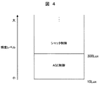
図4は、プログラムAEによって照度レベルに応じて、デバイス制御部127のシャッタ制御部121とAGC制御部122のどちらで制御するかの基準を示す説明図である。露光制御部120において、画像信号レベルが300Luxより低い時は、低照度環境であるためCCDセンサの信号レベルの利得を上げるように従来のAGC制御が選択され、それ以上の明るい照度環境では本発明のシャッタ速度制御が選択され適切な露光に調整される。
(5)フリッカ制御部
次にフリッカ制御部132について説明する。図3においてフリッカ制御部132は、信号レベル差分/平均演算部117、フリッカ判定部118およびフリッカ除去制御部119からなり、フリッカ除去制御を行う。
The
(4) Exposure Control Switching of Device Control Unit FIG. 4 is an explanatory diagram showing a reference for controlling by the
(5) Flicker Control Unit Next, the
信号レベル差分/平均演算部117は、フリッカ判定を行うフリッカ判定部118に必要な情報である、信号レベル差分値DIFFと平均フィールド信号レベルAVEとを生成している。
信号レベル差分値DIFFは、記憶部130に保持された前フィールド信号レベル1AOLDと現在のフィールド信号レベル1Aから次式
DIFF = 1AOLD − 1A ・・・・・・(2)
により計算する。
The signal level difference /
The signal level difference value DIFF is calculated from the previous field signal level 1AOLD and the current field signal level 1A held in the
DIFF = 1AOLD − 1A (2)
Calculate according to
記憶部130に保存されている平均フィールド信号レベルAVEは、電源投入時の初回のみ信号レベル検出部114で検出された信号レベル1Aを記憶部データ参照/記憶部115を介して記憶部130に記憶する。その後は、信号レベル検出部114で検出された現在のフィールド信号レベル1Aと記憶部130に保持する平均フィールド信号レベルAVEを、信号レベル差分/平均演算部117にて、次式に基づいて計算し、
AVE = (1A + AVE)/2 ・・・・・・(3)
計算後の新たな平均フィールド信号レベルAVEを、記憶部データ参照/記憶部115を介して記憶部130に記憶する。以下この処理をフィールド毎に繰り返す。
For the average field signal level AVE stored in the
AVE = (1A + AVE) / 2 (3)
The new average field signal level AVE after calculation is stored in the
フリッカ判定部118では、上記DIFFとAVEのそれぞれがフリッカ判定部118内部で定められた閾値TDIFF、TAVE以上であるかどうか判定を行い、共に閾値以上であればフリッカ有りと判定する。具体的には、信号レベル差分/平均演算部117は記憶部130から前フィールドで算出した平均フィールド信号レベルAVEを記憶部データ参照/記録部115を介して取得し、現在のフィールド信号レベル値1AとAVEの平均を式(3)より計算し、再び記憶部130に信号レベル平均値AVEとして保持し、このAVEが閾値TAVE以上であるか判定を行い、また式(2)より計算されたDIFFが閾値TDIFF以上であるか判定を行う。ただし、本フリッカ判定方法は一例であり、これに限定されることはない。
これを受けて、フリッカ除去制御部119は、露光制御部120に対しフリッカ除去を指示する。露光制御部120は、さらにデバイス制御部127にフリッカ除去処理を指示する。
(6)フリッカ除去処理
フリッカ除去処理は、図3のデバイス制御部127内において、シャッタ制御部121でCCDセンサ104の各フィールドの露光開始位置と露光終了位置をシフトしたシャッタ速度制御を行うことによってフリッカ除去を行う露光期間シフト処理 (処理1)と、信号レベル検出部114から得られるフィールド信号レベル1Aから信号変動分を計算し、フリッカ制御部132を介してデジタルAGC部109で補正を行ってフリッカ除去を行う公知のAGC処理(処理2)とを備える。
The flicker determination unit 118 determines whether each of the above DIFF and AVE is equal to or greater than the threshold values TDIFF and TAVE determined in the flicker determination unit 118. If both are equal to or greater than the threshold value, it is determined that there is flicker. Specifically, the signal level difference /
In response to this, the flicker
(6) Flicker removal processing The flicker removal processing is performed by performing shutter speed control by shifting the exposure start position and exposure end position of each field of the
露光制御部120は、まずフリッカ有りと判定された際には、デバイス制御部127のシャッタ制御部121に指示を出し、処理1である各フィールドの露光開始位置をシフトする露光期間シフトシャッタ速度制御が選択される。それでもフリッカが適切に除去しきれなかった場合には、デジタルAGC109を作動させて処理2であるフリッカによる信号変動分を計算してデジタルAGCで補正するフリッカ除去処理を実行する。
(7)フリッカ除去時のシャッタ速度制御切替え
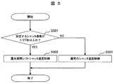
図5に、フリッカ判定部118でフリッカ除去処理1の時に実行するシャッタ速度制御の切替えについてのフローチャートを示す。ステップS501では、設定するシャッタ速度がフリッカを除去できるシャッタ速度1/2T[秒]以上であるか判定を行う。シャッタ速度1/2T[秒]以上の時にはS502にて本発明の露光期間シフトシャッタ速度制御を行う。シャッタ速度が1/2T[秒]よりも低速の時には、ステップS503で従来のシフトなしのシャッタ速度制御を行う。Tは光源発光周波数である。
When it is first determined that there is flicker, the
(7) Shutter Speed Control Switching at Flicker Removal FIG. 5 shows a flowchart for shutter speed control switching executed at the flicker removal processing 1 by the flicker determination unit 118. In step S501, it is determined whether the shutter speed to be set is equal to or higher than the shutter speed 1 / 2T [seconds] at which flicker can be removed. When the shutter speed is 1 / 2T [second] or more, the exposure period shift shutter speed control of the present invention is performed in S502. When the shutter speed is lower than 1 / 2T [second], the conventional shutter speed control without shift is performed in step S503. T is the light source emission frequency.
S502の露光期間シフトシャッタ速度制御は、1/2T[秒]以上の高速なシャッタ速度において、フリッカの発生を完全に除去させかつ動きのある被写体に対して残像やブレを発生させない制御方法である。しかし、1/2T[秒]未満のシャッタ速度の際には露光期間シフトシャッタ速度制御は実行できないので、この低速シャッタ速度に対応するため、フリッカ判定部118でフリッカありと判定された場合は処理2を常に実行可能にしておく。
(8)露光期間シフト制御用CCDセンサ
次に露光期間シフトシャッタ速度制御に用いるCCDセンサについて説明する。使用可能なCCDセンサは、一般的な水平CCDと垂直CCDを各1系統持つプログレッシプ方式またはインターレース方式のCCDセンサ、もしくは電荷を転送する垂直CCDを2系統持つCCDセンサ、あるいは各画素にフォトダイオードの電荷を一時的に保存しておくための記録素子を搭載したCCDセンサ等、種々のCCDセンサが使用される。本実施例では構造が単純な一般的な水平CCDと垂直CCDを各1系統持つCCDセンサを用いて説明する。
The exposure period shift shutter speed control in S502 is a control method that completely eliminates flicker generation and does not cause afterimages and blurring on a moving subject at a high shutter speed of 1 / 2T [seconds] or higher. . However, since the exposure period shift shutter speed control cannot be executed when the shutter speed is less than 1 / 2T [seconds], processing is performed when the flicker determination unit 118 determines that there is flicker in order to cope with this low shutter speed. Make 2 always executable.
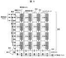
(8) CCD sensor for exposure period shift control Next, a CCD sensor used for exposure period shift shutter speed control will be described. The CCD sensor that can be used is a progressive or interlaced CCD sensor with one general horizontal CCD and one vertical CCD, or a CCD sensor with two vertical CCDs that transfer charges, or a photodiode for each pixel. Various CCD sensors such as a CCD sensor equipped with a recording element for temporarily storing electric charges are used. In this embodiment, a description will be given using a CCD sensor having a simple horizontal CCD and vertical CCD each having a simple structure.
図6に水平CCDと垂直CCDを各1系統持つ一般的なCCDセンサ200の構造を示す。1フィールド期間中にCCDセンサ200上のフォトダイオード201に蓄積された電荷に対して掃き捨てと読み出しが行われる。フォトダイオード201の電荷は電荷掃き捨てパルスによって一旦掃き捨てられ、電荷読み出しパルスによって垂直CCD202に全画素の電荷が転送され、垂直CCD202に転送された各フォトダイオードの電荷は垂直転送パルスによって水平CCD203へ1ライン単位で運ばれ、更に水平転送パルスによって水平CCD203から出力端子に1画素単位で運ばれて、FDアンプ204で電荷を電気信号に変える電荷の検出が行われ各画素の電気信号がCCDセンサから出力されている。
B.露光期間シフトシャッタ速度制御
次に、本発明における露光期間シフトシャッタ速度制御方法について詳細に説明する。
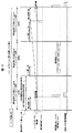
(1)露光期間シフトシャッタ速度時の画像出力方法
図7は露光期間シフトシャッタ速度制御時の画像信号出力方法を説明する模式図である。露光期間シフトシャッタ速度制御に一般的な処理速度を持つCCDセンサを使用した場合には、通常のシャッタ速度制御では1フィールドごとに画像メモリを介して画像出力していた1フィールドで完結するのに対して、2フィールドを必要とする。すなわち、図7中処理A1、処理A2…を処理A、処理B1、処理B2…を処理Bとすれば、処理の異なる処理Aと処理Bの2つの処理で1プロセスが完結する。
FIG. 6 shows the structure of a
B. Exposure Period Shift Shutter Speed Control Next, the exposure period shift shutter speed control method in the present invention will be described in detail.
(1) Image Output Method at Exposure Period Shift Shutter Speed FIG. 7 is a schematic diagram for explaining an image signal output method at exposure period shift shutter speed control. When a CCD sensor with a general processing speed is used for the exposure period shift shutter speed control, the normal shutter speed control is completed in one field where the image was output via the image memory for each field. On the other hand, 2 fields are required. That is, if processing A1, processing A2,... In FIG. 7 are processing A, processing B1, processing B2,... Are processing B, one process is completed by two processings, processing A and processing B, which are different in processing.
図7の処理B毎にCCDセンサから得られた画像データの出力と保存を行い、処理Aでは処理Bで保存した画像データを使用して画像出力を行い、このプロセスを反復実行している。画像データの保存は図3中の画像メモリ112で行い、画像出力は画像出力処理部113から行っている。
The image data obtained from the CCD sensor is output and stored for each process B in FIG. 7, and in process A, the image data stored in process B is used to output an image, and this process is repeatedly executed. Image data is stored in the
ただし、上記2フィールド処理を1フィールド内で処理できる高速CCDセンサであれば、処理Aと処理Bに分ける必要はなく1フィールドで処理することも可能である。例えば、CCDセンサ駆動を通常よりも倍速で駆動させる場合には、例えばNTSC規格のカメラで1フィールド1/60秒で処理しているものを、CCDセンサの動作クロックを2倍にして倍速駆動させ、1フィールド内に処理AでCCDセンサのフォトダイオードに蓄積した電荷を垂直CCDに転送した直後即座に処理Bにて垂直転送パルスと水平転送パルスの印加を倍速で行うことにより、処理BとAを1フィールド期間内に実行でき、別フィールドに分ける必要はない。
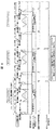
(2)露光期間シフトシャッタ速度制御
以下露光期間シフトシャッタ速度制御時の処理Aと処理BのCCDセンサの制御方法について説明する。図8は露光期間シフトシャッタ速度制御を示すものである。図中では処理A、処理Bを行う各フィールド時間をN8[秒]、設定するシャッタ速度をn8[秒]、各(X-1)フィールド、Xフィールド、(X+1)フィールドにおける露光期間シフト量をそれぞれS(X-1)[秒]、SX[秒] 、S(X+1)[秒]としている。
However, if the high-speed CCD sensor can process the two-field processing in one field, it is not necessary to divide into the processing A and the processing B, and the processing can be performed in one field. For example, when driving the CCD sensor at double speed than normal, for example, what is processed in 1 field 1/60 second with an NTSC standard camera, the CCD sensor operation clock is doubled and double speed drive is performed. Immediately after the charge accumulated in the photodiode of the CCD sensor was transferred to the vertical CCD in process A within one field, the vertical transfer pulse and horizontal transfer pulse were applied at double speed immediately in process B, so that processes B and A Can be executed within one field period and need not be separated into separate fields.
(2) Exposure Period Shift Shutter Speed Control Hereinafter, a process for controlling the CCD sensor in process A and process B during exposure period shift shutter speed control will be described. FIG. 8 shows exposure period shift shutter speed control. In the figure, each field time for processing A and processing B is N8 [seconds], the shutter speed to be set is n8 [seconds], and exposure period shifts in each (X-1) field, X field, and (X + 1) field The quantities are S (X-1) [seconds], SX [seconds], and S (X + 1) [seconds], respectively.
露光期間シフト量とは、各フィールドで光源発光周期の同位相部をCCDセンサで露光するように、露光開始となる電荷掃き捨てパルスと露光終了となる電荷読み出しパルスを印加するタイミングを各フィールドで可変させるためのシフト量を決めるものである。シャッタ速度が同じであっても、上記シフト量に応じて各フィールドで電荷蓄積開始と電荷蓄積終了のタイミングが異なる。 The exposure period shift amount is the timing at which the charge sweep pulse at the start of exposure and the charge readout pulse at the end of exposure are applied in each field so that the CCD sensor exposes the same phase part of the light source emission cycle in each field. The amount of shift for making it variable is determined. Even when the shutter speed is the same, the charge accumulation start timing and the charge accumulation end timing differ in each field according to the shift amount.
また、露光期間シフトはY[field]で完結するように設定されており、図8中ではS(X-1)[秒]、SX[秒] 、S(X+1)[秒]からなる露光期間シフトをシフト実行(X-1)回目、シフト実行X回目、シフト実行(X+1)回目の3つのX[field]からなる1Y[field]のサイクルで繰り返すものとする。 The exposure period shift is set to be completed at Y [field]. In FIG. 8, the exposure period shift is composed of S (X-1) [seconds], SX [seconds], and S (X + 1) [seconds]. It is assumed that the exposure period shift is repeated in a cycle of 1Y [field] including three X [fields] of the shift execution (X-1), the shift execution Xth, and the shift execution (X + 1).
通常のシャッタ速度制御では電荷掃き捨てパルスの印加によりフォトダイオードに蓄積された電荷を電荷読み出しパルスの印加により垂直CCDへ全画素の電荷を転送し、垂直CCDと水平CCDにより垂直転送と水平転送を繰り返してCCDセンサから信号出力している。電荷読み出しパルスの印加は各フィールド周期の境界で実行している。 In normal shutter speed control, the charge accumulated in the photodiode is transferred to the vertical CCD by applying the charge sweep-out pulse, and the vertical and horizontal transfer is performed by the vertical CCD and horizontal CCD. The signal is repeatedly output from the CCD sensor. The application of the charge readout pulse is executed at the boundary of each field period.
これに対し、本発明の実施形態における露光期間シフトシャッタ速度制御の特徴は、第一に、電荷掃き捨てと電荷読み出しの繰り返し処理に1フィールド、垂直CCDと水平CCDでの電荷転送処理に1フィールドを当てて処理Aと処理Bに分離している点であり、通常シャッタ速度制御で1フィールド期間中に一括して行っていた処理を処理Aと処理Bの2回に分けて行っている。 In contrast, the exposure period shift shutter speed control according to the embodiment of the present invention is characterized in that, first, one field is used for repeated charge sweeping and charge readout processing, and one field is used for charge transfer processing in a vertical CCD and a horizontal CCD. The process A and the process B are separated, and the process that is normally performed during one field period under the normal shutter speed control is divided into the process A and the process B twice.
第二に、露光開始タイミングと露光終了タイミングを可変させる露光期間シフト量により、露光開始と露光終了タイミングを各フィールドで可変させている点である。処理Bでは電荷蓄積は行わないが、露光期間シフト量の計算はY[field]サイクルを通して行う必要があり、処理Bの間でも露光期間シフト量の計算を行う。ただし実際に露光期間シフトを実行するのは処理Aのみである。 Second, the exposure start timing and exposure end timing are varied in each field by the exposure period shift amount that varies the exposure start timing and the exposure end timing. Although charge accumulation is not performed in the process B, the calculation of the exposure period shift amount needs to be performed through the Y [field] cycle, and the exposure period shift amount is also calculated during the process B. However, only the process A actually performs the exposure period shift.
露光期間シフト量はフィールド単位で計算する必要がある。この各フィールドでの露光期間シフト量の設定により商用交流電源周波数T[Hz]に依存して発光する照明の発光周期に対して、各フィールドで照明光の周期の同じ位相を露光することができ、各フィールドで同じ露光量にすることができるため、フリッカを確実に除去することが可能である。 The exposure period shift amount must be calculated in field units. By setting the exposure period shift amount in each field, it is possible to expose the same phase of the illumination light cycle in each field with respect to the light emission cycle of the illumination that emits light depending on the commercial AC power supply frequency T [Hz]. Since the same exposure amount can be obtained in each field, flicker can be surely removed.
なお、発光周期に対してどの位相部分を露光するかによって、照明光による露光量が小さくなる場合や照明光を露光できない場合が発生するので、発光周期に対して最適な位相を露光できるように制御している。この制御詳細については後述する。 Depending on which phase part is exposed to the light emission period, the exposure amount by illumination light may be small or the illumination light may not be exposed, so that the optimum phase can be exposed to the light emission period. I have control. Details of this control will be described later.
また、商用交流電源周波数T[Hz]には50[Hz]と60[Hz]があるので、シャッタ速度1/2T[秒]は周波数が50[Hz]の時にはシャッタ速度1/100[秒]、周波数が60[Hz]の時には1/120[秒]となる。この商用交流電源周波数情報は図3の記憶部130に保持されているのでそこから情報を取得し1/2T[秒]は1/100[秒]もしくは1/120[秒]のシャッタ速度となる。
Since commercial AC power supply frequency T [Hz] has 50 [Hz] and 60 [Hz], shutter speed 1 / 2T [second] is shutter speed 1/100 [second] when frequency is 50 [Hz]. When the frequency is 60 [Hz], it is 1/120 [second]. Since this commercial AC power supply frequency information is stored in the
本発明は商用交流電源のみでなく、所定周期で発光している照明であれば、照明の発光周期さえわかれば適用可能な手法である。フリッカ判定部118でフリッカありと判定した場合かつシャッタ速度が1/2T[秒]より高速なシャッタ速度に設定する場合は図8の露光期間シフトシャッタ速度制御を行い、それ未満のシャッタ速度では通常のシャッタ速度制御を行う。
(3)シャッタ速度計算方法
露光期間シフトシャッタ速度制御を実行するには、図3中の各フィールドで露光期間シフトを行うサイクルY[field]と、各フィールドの露光期間シフト量SX(X = 1,2,…:Xは自然数)を計算する必要がある。露光期間シフトは現在フィールドに対する前フィールドで計算された露光期間シフト量S(X-1)から計算され、Y[field]を1サイクルとして処理完結される。
The present invention can be applied not only to a commercial AC power source but also to an illumination that emits light at a predetermined cycle as long as the light emission cycle is known. When the flicker determination unit 118 determines that flicker is present and the shutter speed is set to a shutter speed higher than 1 / 2T [seconds], the exposure period shift shutter speed control in FIG. 8 is performed, and the shutter speed less than that is normal. The shutter speed is controlled.
(3) Shutter Speed Calculation Method To execute exposure period shift shutter speed control, a cycle Y [field] for shifting the exposure period in each field in FIG. 3 and an exposure period shift amount SX (X = 1) in each field. , 2, ...: X is a natural number). The exposure period shift is calculated from the exposure period shift amount S (X-1) calculated in the previous field with respect to the current field, and the process is completed with Y [field] as one cycle.
図3では露光期間シフト実行をS(X-1)、SX、S(X+1)の3回に設定し、3フィールド1サイクル(Y=3)として図示している。各フィールドに対して設定するシャッタ速度は各フィールド共通してn8[秒](露光期間)を設定するものとする。まずシフトするサイクルY[field]の計算を行う。各フィールドの時間はN8秒であり、照明光の周期は商用交流電源周波数をT[Hz]すると2T[Hz]であるので、次式
(2T x Y) / (1/N8) ・・・・・・(4)
による計算結果の余りがゼロ(0)となる最小の値を露光期間シフトを行うサイクルY[field]として求める。
In FIG. 3, the exposure period shift execution is set to three times of S (X-1), SX, and S (X + 1), and is illustrated as three fields and one cycle (Y = 3). The shutter speed set for each field is set to n8 [second] (exposure period) common to each field. First, the shift cycle Y [field] is calculated. The time of each field is N8 seconds, and the period of illumination light is 2T [Hz] when the commercial AC power supply frequency is T [Hz].
(2T x Y) / (1 / N8) (4)
The minimum value for which the remainder of the calculation result obtained by is zero (0) is obtained as the cycle Y [field] for performing the exposure period shift.
次に、各フィールドの露光期間シフト量としてY[field]サイクル中のXフィールド目である露光シフト実行X回目の露光期間シフト量SXの計算方法について下記に示す。まず、(X-1) フィールド目のフィールド期間内に照明光の周期がK8[個]存在するとすれば、K8[個]は、次式
N8 / (1/2T) ・・・・・・(5)
による計算結果の少数点以下を切り捨てた整数値で計算できる。そして、照明光の周期K8[個]の時間T8[秒]を次式
T8 = (1/2T) x K8 [秒] ・・・・・・(6)
で計算する。Y[field]サイクルの(X-1)フィールド目からXフィールド目にまたがっている照明光周期の(X-1)フィールド期間内の1周期未満の時間をt8[秒]とすると、t8[秒]は次式
t8 = N8 - T8 - S(X-1) [秒] ・・・・・・(7)
で計算することができる。
Next, a method for calculating the exposure period shift amount SX of the exposure shift execution Xth time, which is the X field in the Y [field] cycle, as the exposure period shift amount of each field will be described below. First, if there are K8 [number] illumination light periods within the field period of the (X-1) -th field, K8 [number]
N8 / (1 / 2T) ・ ・ ・ ・ ・ ・ (5)
It can be calculated with an integer value obtained by rounding down the decimal point. And the time T8 [second] of the illumination light cycle K8 [pieces]
T8 = (1 / 2T) x K8 [sec] (6)
Calculate with T8 [seconds], where t8 [seconds] is the period of less than one period within the (X-1) field period of the illumination light period that extends from the (X-1) field to the X field of the Y [field] cycle. ] Is the following formula
t8 = N8-T8-S (X-1) [sec] (7)
Can be calculated with
現在のXフィールド期間内で (X-1)フィールド期間内からXフィールド期間内にまたがっている1周期未満の時間を求め、その分現在フィールドであるY[field]サイクル中のXフィールド目の露光開始時間と露光終了時間をシフトすれば、Y[field]サイクル中の(X-1)フィールド目とXフィールド目で照明光の周期が同じ位相となる箇所を露光することができる。 Within the current X field period, (X-1) The time of less than one cycle spanning from the field period to the X field period is obtained, and the exposure for the X field in the current field Y [field] cycle By shifting the start time and the exposure end time, it is possible to expose a portion in the Y [field] cycle where the cycle of the illumination light has the same phase in the (X-1) field and the X field.
そこで、Y[field]サイクル中のXフィールド目で(X-1)フィールド目からまたがっている照明光1周期未満の時間を露光期間シフト量SXとして次式より
SX = (1/2T) - t8 [秒] ・・・・・・(8)
として計算することができる。
Therefore, in the X field in the Y [field] cycle, the time that is less than one cycle of illumination light spanning from the (X-1) field is defined as the exposure period shift amount SX from the following equation:
SX = (1 / 2T)-t8 [sec] (8)
Can be calculated as
式(8)で計算した露光期間シフト量SXが照明光の1周期の時間1/2T[秒]にほぼ近い場合は強制的にSX = 0 とする。SX[秒]と同じくY[field]サイクル中の(X+1)フィールド目の露光期間シフト量S(X+1)[秒]に対しても、同様の方法で計算することができる。
(4) 初期露光期間シフト量の計算方法
ただし、Y[field]サイクルの開始1フィールド目である露光シフト実行(X-1)回目の初期露光期間シフト量については、上記計算によらず次に説明する方法により求めている。
If the exposure period shift amount SX calculated by the equation (8) is substantially close to the time 1 / 2T [second] of one cycle of the illumination light, SX = 0 is forcibly set. Similar to SX [second], the exposure period shift amount S (X + 1) [second] in the (X + 1) -th field in the Y [field] cycle can be calculated in the same manner.
(4) Initial exposure period shift amount calculation method However, the initial exposure period shift amount for the (X-1) th exposure shift execution, which is the first field in the Y [field] cycle, is the next calculation regardless of the above calculation. It is determined by the method explained.
図9に初期露光期間シフト量の計算方法を示す。図3中のフリッカ判定部118でフリッカありと判定され、フリッカ除去制御部119から露光制御部120にフリッカ除去指示が出されて露光期間シフトシャッタ速度制御が実行される場合、露光期間シフトシャッタ速度制御の実行開始直後にまず初期露光期間シフト量の決定が行われる。
FIG. 9 shows a method for calculating the initial exposure period shift amount. When the flicker determination unit 118 in FIG. 3 determines that there is flicker, and when the flicker
露光期間シフトを行うサイクルがY[field]あり、それぞれのフィールドで露光期間シフト量SX(X = 1,2,…:Xは自然数)は異なるので、初期露光期間シフト量となる露光期間シフト量にはY通り(フィールドサイクル)が存在する。そこで、まずそのY[field]サイクルの露光期間シフト実行1回目である露光期間シフトをY通りで実行させる。その際にY[field]サイクルであるフィールドサイクル1の1フィールド目の露光期間シフト量は必ずS1 = 0[秒]とする。 The exposure period shift cycle is Y [field], and the exposure period shift amount SX (X = 1, 2,..., X is a natural number) is different in each field. Therefore, the exposure period shift amount is the initial exposure period shift amount. There are Y ways (field cycles). Therefore, first, the exposure period shift, which is the first exposure period shift execution of the Y [field] cycle, is executed in Y ways. At this time, the exposure period shift amount in the first field of the field cycle 1, which is the Y [field] cycle, is always S1 = 0 [seconds].
図9ではY=3[field]とした例で示しており、露光期間シフトが3通り存在するので、1フィールド目の露光期間シフト量をS1 = 0[秒]としてそれぞれ異なる露光期間シフト量となるフィールドサイクル1(露光期間シフト実行1回目の露光期間シフト量: S1 = 0)、フィールドサイクル2(露光期間シフト実行1回目の露光期間シフト量: S4)、フィールドサイクル3(露光期間シフト実行1回目の露光期間シフト量: S7)から各フィールドサイクルを実行している。露光期間シフト実行1回目の露光期間シフト量: S1[秒]以外の露光期間シフト量は式(5)〜式(8)によって求める。 FIG. 9 shows an example where Y = 3 [field], and there are three exposure period shifts. Therefore, the exposure period shift amount in the first field is set to S1 = 0 [seconds], and different exposure period shift amounts are obtained. Field cycle 1 (exposure period shift execution first exposure period shift amount: S1 = 0), field cycle 2 (exposure period shift execution first exposure period shift amount: S4), field cycle 3 (exposure period shift execution 1 Each field cycle is executed from the exposure time shift amount of the second time: S7). Exposure period shift amount for the first exposure period shift execution: The exposure period shift amount other than S1 [seconds] is obtained by Expressions (5) to (8).
そして、各フィールドサイクルの各フィールドで得られた露光量の和を計算し、最も大きいフィールドサイクルを選択する。図9の例ではフィールドサイクル2が選択される。このフィールドサイクル2の露光期間シフト実行1回目の露光期間シフト量S4が初期露光期間シフト量となる。これにより、照明光の周期中で最も露光量が得られる位相でCCDセンサが露光できることになる。 Then, the sum of the exposure amounts obtained in each field of each field cycle is calculated, and the largest field cycle is selected. In the example of FIG. 9, field cycle 2 is selected. The exposure period shift amount S4 for the first execution of the exposure period shift in the field cycle 2 is the initial exposure period shift amount. As a result, the CCD sensor can be exposed at a phase at which the exposure amount is most obtained during the period of the illumination light.
また、露光期間シフトシャッタ速度制御中、CCDセンサは照明光を常に一定の光量で安定して露光することが可能であり、例えば、LED照明光のような点灯と消灯を商用電源周期で繰り返している照明光であったとしても、確実にLED照明光の点灯部の位相を露光することができ、CCDセンサがLED照明光の光を捉えられないということがなくなる。
(5)露光期間シフトシャッタ速度計算の具体例
上記式(4)〜式(8)によって計算される各フィールドで露光期間シフトを行うサイクルY[field]と露光期間シフト量SX[秒]の計算の具体例を示す。商用交流電源周波数T = 50[Hz]、CCDセンサ1フィールドの時間がN8 = 1/60[秒]、初期露光期間シフト量を0.003333[秒]とした場合にシャッタ速度をS8 = 1/180[秒]に設定する時の計算方法を説明する。まず、露光期間シフトするサイクルY[field]の計算を行う。商用交流電源周波数T = 50[Hz]でCCDセンサ1フィールドの時間がN8 = 1/60[秒]であるので、式(4)を計算した時の余りがゼロ(0)となるYの値は式(9)よりY = 3 として計算される。
(2T x Y) / (1/N8) = (2 x 50 x 3) / (1/(1/60)) = 5 余り0 (Y = 3) ・・・・・・(9)
これより露光期間シフトするサイクルは3[field]となる。
In addition, during exposure period shift shutter speed control, the CCD sensor can stably expose illumination light with a constant light amount, for example, turning on and off like LED illumination light in a commercial power cycle. Even if the illumination light is light, the phase of the lighting part of the LED illumination light can be reliably exposed, and the CCD sensor can no longer capture the light of the LED illumination light.
(5) Specific Example of Exposure Period Shift Shutter Speed Calculation Calculation of cycle Y [field] for performing exposure period shift in each field calculated by the above equations (4) to (8) and exposure period shift amount SX [second] A specific example is shown. When commercial AC power supply frequency T = 50 [Hz], CCD sensor 1 field time is N8 = 1/60 [second], and initial exposure period shift amount is 0.003333 [second], shutter speed is S8 = 1/180 [ The calculation method when setting to [second] will be described. First, a cycle Y [field] for shifting the exposure period is calculated. Since the AC power supply frequency T = 50 [Hz] and the CCD sensor 1 field time is N8 = 1/60 [seconds], the value of Y when the remainder when calculating Equation (4) is zero (0) Is calculated as Y = 3 from Equation (9).
(2T x Y) / (1 / N8) = (2 x 50 x 3) / (1 / (1/60)) = 5 remainder 0 (Y = 3) (9)
Thus, the cycle for shifting the exposure period is 3 [field].
3[filed]サイクルの1フィールド目は露光期間シフトシャッタ速度制御の実行直後に計算された初期露光期間シフト量S1 = 0.003333[秒]を設定しており、2フィールド目以降の露光期間シフト量を式(5)〜式(8)により計算する。以下に式(5)〜式(8)より2フィールド目の露光期間シフト量S2[秒]を求める。1フィールド目のフィールド期間内に照明光の周期がK8[個]存在するとすれば、K8[個]は式(5)による計算結果の少数点以下を切り捨てた整数値として式(10)で計算される。
N8 / (1/2T) = (1/60) / (1/(2 x 50)) = 1.666…
→小数点以下切り捨て:1[個] ・・・・・・(10)
そして、照明光の周期K8[個]の時間T8[秒]は式(6)より式(11)で計算される。
T8 = (1/(2 x T)) x K8 = (1/(2 x 50)) x 1 = 0.01 [秒] ・・・(11)
3[field]サイクルの1フィールド目から2フィールド目にまたがっている照明光周期の1フィールド期間内の1周期未満の時間t8[秒]は、式(7)より式(12)で計算される。
t8 = N8 - T8 - S1 = (1/60) - 0.01 - 0.003333
= 0.0033336666666666666666666666666667 ≒ 0.003334[秒] ・・・・・・(12)
そして、3[field]サイクル中の2フィールド目で1フィールド目からまたがっている照明光1周期未満の時間である露光期間シフト量S2は、式(8)より式(13)で計算される。
S2 = (1/(2 x T)) - t8 = (1/(2 x 50)) - 0.003334 = 0.006666 [秒] ・・・・・・(13)
同様にして3[field]サイクル中の3フィールド目の露光期間シフト量S3を計算するとS3 = 0.009999[秒]となり、これは照明光の1周期の時間1/(2 x 50) = 0.01[秒]に近似されるのでS3 = 0[秒]として計算される。
In the first field of the 3 [filed] cycle, the initial exposure period shift amount S1 = 0.003333 [seconds] calculated immediately after execution of the exposure period shift shutter speed control is set, and the exposure period shift amount for the second and subsequent fields is set. Calculation is performed using Equation (5) to Equation (8). The exposure period shift amount S2 [second] in the second field is obtained from Equations (5) to (8) below. If the illumination light period is K8 [number] within the field period of the first field, K8 [number] is calculated by equation (10) as an integer value obtained by rounding down the decimal point of the calculation result by equation (5). Is done.
N8 / (1 / 2T) = (1/60) / (1 / (2 x 50)) = 1.666…
→ rounded down to the nearest decimal point: 1 [pieces] (10)
The time T8 [second] of the illumination light period K8 [pieces] is calculated from equation (6) according to equation (11).
T8 = (1 / (2 x T)) x K8 = (1 / (2 x 50)) x 1 = 0.01 [sec] (11)
The time t8 [second] within one field period of the illumination light period spanning from the first field to the second field of the 3 [field] cycle is calculated by the expression (12) from the expression (7). .
t8 = N8-T8-S1 = (1/60)-0.01-0.003333
= 0.0033336666666666666666666666666667 ≒ 0.003334 [sec] ・ ・ ・ ・ ・ ・ (12)
Then, the exposure period shift amount S2, which is a time of less than one cycle of the illumination light spanning from the first field in the second field in the 3 [field] cycles, is calculated by Expression (13) from Expression (8).
S2 = (1 / (2 x T))-t8 = (1 / (2 x 50))-0.003334 = 0.006666 [sec] ・ ・ ・ ・ ・ ・ (13)
Similarly, when the exposure period shift amount S3 of the third field in the 3 [field] cycle is calculated, S3 = 0.009999 [seconds], which is one period of illumination light 1 / (2 × 50) = 0.01 [seconds] ] Is calculated as S3 = 0 [seconds].
以上により、1フィールド目の初期露光期間シフト量をS1 = 0.003333[秒]、2フィールド目の初期露光期間シフト量をS2 = 0.006666[秒]、3フィールド目の初期露光期間シフト量をS3 = 0 [秒]とした3[field]サイクルで露光期間をシフトさせ、この処理を繰り返してシャッタ速度制御を行えば、フリッカを除去しつつ1/100秒以上の高速シャッタ速度を実現させ、かつ動きのある被写体を撮影しても残像やブレを発生させることなくカメラを撮影することができる。
C.具体的な光源への適用
(1)蛍光灯フリッカの除去
図10に、蛍光灯フリッカありの場合でかつシャッタ速度が1/2T[秒]よりも高速なシャッタ速度n10[秒]を設定した時に、フリッカが発生していない様子を示す。図10は1/2T[秒]以上のシャッタ速度S10[秒]設定時に通常シャッタ速度制御と露光期間シフトシャッタ速度制御を行った際の比較を示している。通常のシャッタ速度制御では電荷掃き捨てパルスとカメラ1フィールドと1フィールドの境界付近の電荷読み出しパルスを1フィールドに各1回印加し、電荷掃き捨てパルスから電荷読み出しパルスが印加された時間がシャッタ速度n10[秒]となる。
As described above, the initial exposure period shift amount of the first field is S1 = 0.003333 [seconds], the initial exposure period shift amount of the second field is S2 = 0.006666 [seconds], and the initial exposure period shift amount of the third field is S3 = 0. Shifting the exposure period in 3 [field] cycles [seconds] and repeating this process to control the shutter speed achieves a high shutter speed of 1/100 seconds or more while eliminating flicker and Even if a certain subject is photographed, the camera can be photographed without causing an afterimage or blurring.
C. Application to concrete light sources
(1) Elimination of fluorescent lamp flicker FIG. 10 shows that there is no flicker when there is a fluorescent lamp flicker and the shutter speed is set to a shutter speed n10 [second] faster than 1 / 2T [second]. Show the state. FIG. 10 shows a comparison between normal shutter speed control and exposure period shift shutter speed control when the shutter speed S10 [second] is set to 1 / 2T [second] or higher. In normal shutter speed control, the charge sweep pulse and the charge readout pulse near the boundary between the camera 1 field and 1 field are applied once to each field, and the time when the charge readout pulse is applied from the charge sweep pulse is the shutter speed. n10 [seconds].
それに対し露光期間シフトシャッタ速度制御ではシャッタ速度n10[秒]を設定する場合に各フィールドで計算される露光期間シフト量に応じて電荷掃き捨てパルスと電荷読み出しパルスの印加タイミングをシフトさせる。電荷読み出しパルスは1フィールドと1フィールドの境界付近の印加に限定されない制御を行う。 On the other hand, in the exposure period shift shutter speed control, when the shutter speed n10 [second] is set, the application timing of the charge sweep-out pulse and the charge readout pulse is shifted according to the exposure period shift amount calculated in each field. The charge readout pulse is controlled not limited to application near the boundary between one field and one field.
これにより各フィールドで常に同じ蛍光灯の発光周期中の最も露光量が大きい位相ポイントでシャッタを設定することができ、シャッタ高速時でもフリッカを除去し、なおかつ通常シャッタ速度制御と同様に被写体の残像やブレを抑えることができる。
(2)LEDフリッカの除去
また、図11は商用交流電源の周波数の周期T[Hz]を全波整流して2T[Hz]の周期で消灯と点灯を繰り返して発光しているLED照明を1/2T[秒]より高速なシャッタ速度n11[秒]を設定した際に通常シャッタ速度制御と露光期間シフトシャッタ速度制御を行った際の比較を示している。通常シャッタ速度制御でシャッタ速度n11[秒]を設定した場合、シャッタ速度が高速になる程に各フィールドの露光量の差が大きくなり蛍光灯よりも激しいフリッカとなる。
As a result, the shutter can always be set at the phase point where the exposure amount is the largest during the same fluorescent lamp light emission period in each field, flicker is eliminated even at high shutter speeds, and the afterimage of the subject is the same as in normal shutter speed control. And blurring can be suppressed.
(2) Elimination of LED flicker In addition, Fig. 11 shows the LED lighting that emits light by repeating full-wave rectification of the frequency period T [Hz] of the commercial AC power supply and repeatedly turning it off and on at a frequency of 2 T [Hz]. A comparison between normal shutter speed control and exposure period shift shutter speed control when a shutter speed n11 [second] higher than / 2T [second] is set is shown. When the shutter speed n11 [seconds] is set in the normal shutter speed control, the difference in exposure amount between fields increases as the shutter speed increases, resulting in a flicker that is more intense than that of a fluorescent lamp.
しかし、露光期間シフトシャッタ速度制御を行うことにより、各フィールドで常に同じLED照明の発光周期中の最も露光量が大きい位相ポイントでシャッタを設定することができ、シャッタ速度を1/2T[秒]以上に設定してもフリッカを発生させないようにすることができる。また、LED照明光だけでなく、画像に動きのある被写体が含まれているシーンを撮影した場合でも被写体の残像とブレを増加させることなく、通常シャッタ速度制御と同様に撮影することができる。 However, by performing exposure period shift shutter speed control, the shutter can always be set at the phase point with the largest exposure amount during the same LED illumination emission period in each field, and the shutter speed is reduced to 1 / 2T [seconds]. Flicker can be prevented from being generated even when the above setting is made. Further, not only the LED illumination light but also a scene in which a moving subject is included in the image can be captured in the same manner as the normal shutter speed control without increasing the afterimage and blur of the subject.
固体撮像素子を用いて動画記録を行う撮像装置の、画像周期とある特定周期で発光している照明の周期が異なる場合に発生するフリッカによる画像劣化を完全に除去しながら、残像やブレを増幅させることなく露光調整を行うのに効果を発揮する。 An imaging device that uses a solid-state image sensor to record moving images amplifies afterimages and blurring while completely eliminating image degradation caused by flicker that occurs when the image period and the illumination period that emits light at a specific period are different. This is effective for adjusting the exposure without causing exposure.
101…レンズ、102…アイリス、103…レンズユニット、104…CCDセンサ、105…CDS、アナログAGC…106、A/D…107、AFE…108、デジタルAGC…109、輝度信号色信号生成部…110、各種画像処理部…111、画像メモリ…112、画像出力処理部…113、信号レベル検出部…114、記憶部データ参照/記録部…115、補正量算出部…116、信号レベル差分/平均演算部…117、フリッカ判定部…118、フリッカ除去制御部…119、露光制御部…120、シャッタ制御部…121、AGC制御部…122、パルスタイミング管理部…123、電荷掃き捨てパルス生成部…124、電荷読み出しパルス生成部…125、転送パルス生成部…126、デバイス制御部…127、画像処理LSI…128、記録装置…129、記憶部…130、マイコン制御部…131、フリッカ制御部…132
DESCRIPTION OF
Claims (8)
前記CCDセンサの露光制御のためのシャッタ速度制御に、露光開始時の電荷掃き捨てパルスと、露光終了時の電荷読み出しパルスの印加タイミングを各フィールドで可変させ、露光期間をフィールド内でシフトさせる露光期間シフト量によるシャッタ速度制御を行い、各フィールドにおいて前記光源発光周期の同位相部を前記CCDセンサで露光してフリッカを除去することを特徴とする撮像装置の露光制御方法。 In an exposure control method of an imaging apparatus that performs recording with a CCD sensor using a light source that emits light at a specific period, using an imaging apparatus having a unique field period that is an image output unit,
Exposure that shifts the exposure period within the field by varying the application timing of the charge sweep-out pulse at the start of exposure and the charge readout pulse at the end of exposure to the shutter speed control for exposure control of the CCD sensor. An exposure control method for an imaging apparatus, wherein shutter speed control is performed based on a period shift amount, and flicker is removed by exposing the same phase portion of the light source emission cycle in each field with the CCD sensor.
前記露光期間シフトシャッタ速度制御は、所定数の連続したフィールドを単位として繰り返し実行されることを特徴とする撮像装置の露光制御方法。 In the exposure control method of the imaging device according to any one of claims 1 to 3,
The exposure control method for an imaging apparatus, wherein the exposure period shift shutter speed control is repeatedly executed in units of a predetermined number of continuous fields.
前記シャッタ制御部は、前記CCDセンサに露光開始時の電荷掃き捨てパルスと、露光終了時の電荷読み出しパルスの印加タイミングを各フィールドで可変させ、露光期間をシフトさせてシャッタ速度制御を行い、各フィールドにおいて前記光源発光周期の同位相部を前記CCDセンサで露光することを特徴とする撮像装置。 A lens that captures an image of an object illuminated by a light source that emits light at a specific period, a CCD sensor that converts the captured image into an image signal, a flicker control unit that determines flicker of the image signal and instructs flicker removal, The image processing apparatus includes an exposure control unit that controls exposure according to an instruction from the flicker control unit, and a shutter control unit that performs shutter speed control of the CCD sensor according to an instruction from the exposure control unit. In an imaging device that performs recording using a unique field period,
The shutter control unit varies the application timing of the charge sweep-out pulse at the start of exposure and the charge read-out pulse at the end of exposure in each field to the CCD sensor, performs the shutter speed control by shifting the exposure period, An imaging apparatus, wherein the CCD sensor exposes the same phase part of the light source emission period in the field.
Priority Applications (3)
| Application Number | Priority Date | Filing Date | Title |
|---|---|---|---|
| JP2010055253A JP2011193065A (en) | 2010-03-12 | 2010-03-12 | Imaging equipment |
| CN2011100368768A CN102196184A (en) | 2010-03-12 | 2011-02-10 | Imaging equipment |
| US13/030,299 US20110221929A1 (en) | 2010-03-12 | 2011-02-18 | Imaging equipment and exposure control method of the same |
Applications Claiming Priority (1)
| Application Number | Priority Date | Filing Date | Title |
|---|---|---|---|
| JP2010055253A JP2011193065A (en) | 2010-03-12 | 2010-03-12 | Imaging equipment |
Publications (1)
| Publication Number | Publication Date |
|---|---|
| JP2011193065A true JP2011193065A (en) | 2011-09-29 |
Family
ID=44559624
Family Applications (1)
| Application Number | Title | Priority Date | Filing Date |
|---|---|---|---|
| JP2010055253A Pending JP2011193065A (en) | 2010-03-12 | 2010-03-12 | Imaging equipment |
Country Status (3)
| Country | Link |
|---|---|
| US (1) | US20110221929A1 (en) |
| JP (1) | JP2011193065A (en) |
| CN (1) | CN102196184A (en) |
Cited By (2)
| Publication number | Priority date | Publication date | Assignee | Title |
|---|---|---|---|---|
| WO2016031402A1 (en) * | 2014-08-27 | 2016-03-03 | ソニー株式会社 | Image pickup device and control method for image pickup device |
| KR20170001581A (en) | 2015-06-25 | 2017-01-04 | 미쓰보시 다이야몬도 고교 가부시키가이샤 | Imaging device |
Families Citing this family (17)
| Publication number | Priority date | Publication date | Assignee | Title |
|---|---|---|---|---|
| DE102013100804A1 (en) | 2013-01-28 | 2014-07-31 | Conti Temic Microelectronic Gmbh | Method for detecting pulsed light sources |
| US9596417B2 (en) | 2013-02-26 | 2017-03-14 | Cornell University | Event correlation using data having different time resolutions |
| JP2015115922A (en) * | 2013-12-16 | 2015-06-22 | オリンパス株式会社 | Imaging apparatus and imaging method |
| CN103945136B (en) * | 2014-04-04 | 2017-03-08 | 苏州思源科安信息技术有限公司 | The iris image photo electric imaging system of high user experience degree |
| CN104506779B (en) * | 2014-12-24 | 2018-11-13 | 浙江宇视科技有限公司 | A kind of traffic lights color antidote and picture pick-up device |
| CN107431759B (en) * | 2015-04-09 | 2021-06-15 | 索尼公司 | Imaging device, imaging method, electronic apparatus, and in-vehicle electronic apparatus |
| KR20180083593A (en) * | 2017-01-13 | 2018-07-23 | 삼성전자주식회사 | Image processing method and electronic device implementing the same |
| JP2019036907A (en) | 2017-08-21 | 2019-03-07 | ソニーセミコンダクタソリューションズ株式会社 | Imaging apparatus and device |
| US20190124290A1 (en) * | 2017-10-20 | 2019-04-25 | Shenzhen Matego Electronics Technology Co., Ltd. | Dashboard Camera |
| JP6945660B2 (en) * | 2018-02-09 | 2021-10-06 | オリンパス株式会社 | Imaging system and processing equipment |
| JP7224839B2 (en) * | 2018-10-09 | 2023-02-20 | キヤノン株式会社 | Imaging device and its control method |
| EP3884659A4 (en) | 2018-11-26 | 2021-12-15 | Guangdong Oppo Mobile Telecommunications Corp., Ltd. | Method, system, and computer-readable medium for image sensor communication using different sending data sequence rate and receiving frame rate |
| CN109618113B (en) * | 2019-03-11 | 2019-05-21 | 上海奕瑞光电子科技股份有限公司 | Automatic exposure control method and auto-exposure control component system |
| CN113796066B (en) * | 2019-05-09 | 2023-04-04 | 奥林巴斯株式会社 | Imaging system, endoscope system, light source device, and control method for light source device |
| CN113160590B (en) * | 2020-01-23 | 2023-02-03 | 华为技术有限公司 | Control method and device of intelligent automobile and related equipment |
| CN113364989B (en) * | 2020-03-06 | 2023-04-07 | 浙江宇视科技有限公司 | Camera strobe control method and device, electronic equipment and storage medium |
| CN113347375B (en) * | 2021-06-01 | 2023-01-03 | 天津大学 | Pixel flicker suppression method of pulse image sensor |
Citations (5)
| Publication number | Priority date | Publication date | Assignee | Title |
|---|---|---|---|---|
| JPH05316430A (en) * | 1992-05-11 | 1993-11-26 | Mitsubishi Electric Corp | Image pickup device and imaging device |
| JPH0678223A (en) * | 1992-08-25 | 1994-03-18 | Mitsubishi Electric Corp | Image pickup device |
| JP2003244555A (en) * | 2002-02-21 | 2003-08-29 | Sony Corp | Imaging apparatus and method |
| JP2006084556A (en) * | 2004-09-14 | 2006-03-30 | Pentax Corp | Focus detecting device |
| JP2007336470A (en) * | 2006-06-19 | 2007-12-27 | Sony Corp | Imaging apparatus and imaging method |
Family Cites Families (8)
| Publication number | Priority date | Publication date | Assignee | Title |
|---|---|---|---|---|
| JPH08294058A (en) * | 1995-04-24 | 1996-11-05 | Sony Corp | Solid-state image pickup device and video camera with solid-state image pickup device mounted thereon |
| JP3908606B2 (en) * | 2002-06-19 | 2007-04-25 | 三菱電機株式会社 | Imaging device, imaging method, and portable terminal device including the same |
| KR100578647B1 (en) * | 2004-04-27 | 2006-05-11 | 매그나칩 반도체 유한회사 | Method for integration of image sensor |
| US7920175B2 (en) * | 2005-01-13 | 2011-04-05 | Canon Kabushiki Kaisha | Electronic still camera performing composition of images and image capturing method therefor |
| JP4539449B2 (en) * | 2005-06-10 | 2010-09-08 | ソニー株式会社 | Image processing apparatus and imaging apparatus |
| JP4483744B2 (en) * | 2005-08-26 | 2010-06-16 | ソニー株式会社 | Imaging apparatus and imaging control method |
| JP4948090B2 (en) * | 2006-08-25 | 2012-06-06 | キヤノン株式会社 | Imaging apparatus and drive control method |
| JP4836896B2 (en) * | 2007-08-27 | 2011-12-14 | 三洋電機株式会社 | Video camera |
-
2010
- 2010-03-12 JP JP2010055253A patent/JP2011193065A/en active Pending
-
2011
- 2011-02-10 CN CN2011100368768A patent/CN102196184A/en active Pending
- 2011-02-18 US US13/030,299 patent/US20110221929A1/en not_active Abandoned
Patent Citations (5)
| Publication number | Priority date | Publication date | Assignee | Title |
|---|---|---|---|---|
| JPH05316430A (en) * | 1992-05-11 | 1993-11-26 | Mitsubishi Electric Corp | Image pickup device and imaging device |
| JPH0678223A (en) * | 1992-08-25 | 1994-03-18 | Mitsubishi Electric Corp | Image pickup device |
| JP2003244555A (en) * | 2002-02-21 | 2003-08-29 | Sony Corp | Imaging apparatus and method |
| JP2006084556A (en) * | 2004-09-14 | 2006-03-30 | Pentax Corp | Focus detecting device |
| JP2007336470A (en) * | 2006-06-19 | 2007-12-27 | Sony Corp | Imaging apparatus and imaging method |
Cited By (3)
| Publication number | Priority date | Publication date | Assignee | Title |
|---|---|---|---|---|
| WO2016031402A1 (en) * | 2014-08-27 | 2016-03-03 | ソニー株式会社 | Image pickup device and control method for image pickup device |
| US10244183B2 (en) | 2014-08-27 | 2019-03-26 | Sony Corporation | Image capturing device and method of controlling image capturing device |
| KR20170001581A (en) | 2015-06-25 | 2017-01-04 | 미쓰보시 다이야몬도 고교 가부시키가이샤 | Imaging device |
Also Published As
| Publication number | Publication date |
|---|---|
| US20110221929A1 (en) | 2011-09-15 |
| CN102196184A (en) | 2011-09-21 |
Similar Documents
| Publication | Publication Date | Title |
|---|---|---|
| JP2011193065A (en) | Imaging equipment | |
| JP4106554B2 (en) | Imaging environment determination method and imaging apparatus | |
| JP3826904B2 (en) | Imaging apparatus and flicker reduction method | |
| JP4423889B2 (en) | Flicker reduction method, imaging apparatus, and flicker reduction circuit | |
| JP4487640B2 (en) | Imaging device | |
| JP5035025B2 (en) | Image processing apparatus, flicker reduction method, imaging apparatus, and flicker reduction program | |
| JP4646655B2 (en) | Solid-state imaging device, driving method thereof, and imaging system | |
| JP2007174537A (en) | Imaging apparatus | |
| JP2007060585A (en) | Exposure control method, exposure control apparatus, and imaging apparatus | |
| JP2015115922A (en) | Imaging apparatus and imaging method | |
| JP2008109370A (en) | Image correcting device and method, and imaging apparatus | |
| WO2010044227A1 (en) | Imaging device | |
| JP2006345368A (en) | Image processing apparatus and imaging apparatus | |
| JP2006186593A (en) | Imaging apparatus and control method thereof | |
| JP3908606B2 (en) | Imaging device, imaging method, and portable terminal device including the same | |
| JP2010028180A (en) | Video camera | |
| JPH11164192A (en) | Image-pickup method and device | |
| JP4026890B2 (en) | Electronic camera and electronic shutter control method thereof | |
| JP2007158964A (en) | Image processing apparatus and imaging device | |
| JP5720250B2 (en) | Imaging apparatus and image processing control program | |
| JP2007329604A (en) | Fluorescent light flicker detection circuit | |
| JP4958732B2 (en) | Flicker correction device | |
| JP2000032352A (en) | Video camera device | |
| JP2006050031A (en) | Photographing apparatus | |
| JP2011097204A (en) | Imaging apparatus |
Legal Events
| Date | Code | Title | Description |
|---|---|---|---|
| A621 | Written request for application examination |
Free format text: JAPANESE INTERMEDIATE CODE: A621 Effective date: 20111221 |
|
| A977 | Report on retrieval |
Free format text: JAPANESE INTERMEDIATE CODE: A971007 Effective date: 20120413 |
|
| A131 | Notification of reasons for refusal |
Free format text: JAPANESE INTERMEDIATE CODE: A131 Effective date: 20120417 |
|
| A02 | Decision of refusal |
Free format text: JAPANESE INTERMEDIATE CODE: A02 Effective date: 20120807 |