JP2011192578A - Wire harness - Google Patents
Wire harness Download PDFInfo
- Publication number
- JP2011192578A JP2011192578A JP2010059108A JP2010059108A JP2011192578A JP 2011192578 A JP2011192578 A JP 2011192578A JP 2010059108 A JP2010059108 A JP 2010059108A JP 2010059108 A JP2010059108 A JP 2010059108A JP 2011192578 A JP2011192578 A JP 2011192578A
- Authority
- JP
- Japan
- Prior art keywords
- harness
- half pipe
- wire harness
- main body
- wire
- Prior art date
- Legal status (The legal status is an assumption and is not a legal conclusion. Google has not performed a legal analysis and makes no representation as to the accuracy of the status listed.)
- Granted
Links
Images


Classifications
-
- B—PERFORMING OPERATIONS; TRANSPORTING
- B60—VEHICLES IN GENERAL
- B60R—VEHICLES, VEHICLE FITTINGS, OR VEHICLE PARTS, NOT OTHERWISE PROVIDED FOR
- B60R16/00—Electric or fluid circuits specially adapted for vehicles and not otherwise provided for; Arrangement of elements of electric or fluid circuits specially adapted for vehicles and not otherwise provided for
- B60R16/02—Electric or fluid circuits specially adapted for vehicles and not otherwise provided for; Arrangement of elements of electric or fluid circuits specially adapted for vehicles and not otherwise provided for electric constitutive elements
- B60R16/0207—Wire harnesses
- B60R16/0215—Protecting, fastening and routing means therefor
-
- H—ELECTRICITY
- H02—GENERATION; CONVERSION OR DISTRIBUTION OF ELECTRIC POWER
- H02G—INSTALLATION OF ELECTRIC CABLES OR LINES, OR OF COMBINED OPTICAL AND ELECTRIC CABLES OR LINES
- H02G3/00—Installations of electric cables or lines or protective tubing therefor in or on buildings, equivalent structures or vehicles
- H02G3/30—Installations of cables or lines on walls, floors or ceilings
- H02G3/32—Installations of cables or lines on walls, floors or ceilings using mounting clamps
-
- H—ELECTRICITY
- H02—GENERATION; CONVERSION OR DISTRIBUTION OF ELECTRIC POWER
- H02G—INSTALLATION OF ELECTRIC CABLES OR LINES, OR OF COMBINED OPTICAL AND ELECTRIC CABLES OR LINES
- H02G3/00—Installations of electric cables or lines or protective tubing therefor in or on buildings, equivalent structures or vehicles
- H02G3/02—Details
- H02G3/04—Protective tubing or conduits, e.g. cable ladders or cable troughs
- H02G3/0462—Tubings, i.e. having a closed section
- H02G3/0468—Corrugated
-
- H—ELECTRICITY
- H02—GENERATION; CONVERSION OR DISTRIBUTION OF ELECTRIC POWER
- H02G—INSTALLATION OF ELECTRIC CABLES OR LINES, OR OF COMBINED OPTICAL AND ELECTRIC CABLES OR LINES
- H02G3/00—Installations of electric cables or lines or protective tubing therefor in or on buildings, equivalent structures or vehicles
- H02G3/02—Details
- H02G3/04—Protective tubing or conduits, e.g. cable ladders or cable troughs
- H02G3/0462—Tubings, i.e. having a closed section
- H02G3/0487—Tubings, i.e. having a closed section with a non-circular cross-section
Abstract
Description
本発明は、自動車に配索されるワイヤハーネスに関する。 The present invention relates to a wire harness routed in an automobile.
下記特許文献1に開示されたワイヤハーネスは、複数本の非シールド電線と、金属製のシールドパイプとを備えている。複数本の非シ−ルド電線は、この全体がシールドパイプに挿通されて電磁シールドが施されるとともに、外部に対する保護がなされるようになっている。
The wire harness disclosed in the following
上記従来のワイヤハーネスにあっては、シールドパイプに曲げ加工を施す必要があり、この場合、複数の非シ−ルド電線を予めシールドパイプに挿通しておかなければならず、ワイヤハーネスの製造手順が制約されてしまうという問題点を有している。また、非シールド電線の挿通(通線作業)においては、シールドパイプが大径のものであれば挿通が簡単であるが、実際には小径であることから挿通が難しく、作業が繁雑になってしまうという問題点を有している。 In the above-described conventional wire harness, it is necessary to bend the shield pipe. In this case, a plurality of non-shielded wires must be inserted in the shield pipe in advance, and the procedure for manufacturing the wire harness Has the problem of being restricted. In addition, in the insertion of the unshielded electric wire (wiring work), if the shield pipe has a large diameter, the insertion is easy, but in practice the insertion is difficult due to the small diameter, and the work becomes complicated. It has the problem that it ends up.
ところで、近年の自動車部品にあっては、軽量化の要求があることから、この要求に対応できるようにすることが重要である。 By the way, since there is a demand for weight reduction in recent automobile parts, it is important to be able to meet this demand.
本発明は、上記した事情に鑑みてなされたもので、製造手順の自由度を高め、また、作業性の向上を図り、さらには、軽量化を図ることを可能とするワイヤハーネスを提供することを課題とする。 The present invention has been made in view of the above-described circumstances, and provides a wire harness that can increase the degree of freedom of manufacturing procedures, improve workability, and further reduce the weight. Is an issue.
上記課題を解決するためになされた請求項1記載の本発明のワイヤハーネスは、複数本の高圧導電路を含んでなるハーネス本体と、該ハーネス本体における車両フロアの配索対象部分に設けられて前記車両フロアに固定されるハーネス付属部材とを備えるとともに、該ハーネス付属部材を前記車両フロアに対向する側と前記ハーネス本体の引き出し側とを連続して開口させる略軒樋形状に形成することを特徴とする。
The wire harness of the present invention according to
このような特徴を有する本発明によれば、略軒樋形状のハーネス付属部材にハーネス本体を収容し、そして、このハーネス付属部材を車両フロアに固定すると、ハーネス本体は車両フロアに沿って配索される。ハーネス本体の収容は、ハーネス付属部材が略軒樋形状であり、三方が連続して開口するような形状であることから、通線することなく簡単に行うことが可能である。また、ハーネス付属部材が略軒樋形状であることから、製造手順に自由度を持たせることも可能である。ハーネス付属部材は、例えば同じようなサイズのパイプと比較した場合、少なくとも車両フロアに対向する開口側の分だけパイプよりも軽量化を図ることが可能である。本発明において、高圧導電路は、高圧の電線やバスバー等であるものとする。 According to the present invention having such a feature, when the harness main body is accommodated in the harness attachment member having a substantially eaves-and-eave shape, and the harness attachment member is fixed to the vehicle floor, the harness main body is routed along the vehicle floor. Is done. The harness main body can be easily accommodated without being connected because the harness accessory member has a substantially eaves-like shape and is continuously open on three sides. In addition, since the harness attachment member has a substantially eaves shape, it is possible to give a degree of freedom to the manufacturing procedure. For example, when compared with a pipe having a similar size, the harness attachment member can be lighter than the pipe by at least the opening side facing the vehicle floor. In the present invention, the high-voltage conductive path is a high-voltage electric wire, a bus bar, or the like.
請求項2記載の本発明のワイヤハーネスは、請求項1に記載のワイヤハーネスにおいて、前記ハーネス本体と前記車両フロアとの間に介在する本体保護部材を備えることを特徴とする。 A wire harness according to a second aspect of the present invention is the wire harness according to the first aspect, further comprising a main body protection member interposed between the harness main body and the vehicle floor.
このような特徴を有する本発明によれば、仮に車両フロアにバリ等が生じて配索対象部分の状態が多少悪くとも、ハーネス本体の間に介在する本体保護部材により損傷を防止することが可能である。 According to the present invention having such a feature, even if burrs or the like are generated on the vehicle floor and the state of the portion to be routed is somewhat bad, it is possible to prevent damage by the body protection member interposed between the harness bodies. It is.
請求項3記載の本発明のワイヤハーネスは、請求項1又は請求項2に記載のワイヤハーネスにおいて、前記ハーネス本体を前記ハーネス付属部材の内面に直接又は間接的に接触させるように収容することを特徴とする。 A wire harness according to a third aspect of the present invention is the wire harness according to the first or second aspect, wherein the harness main body is accommodated so as to directly or indirectly contact the inner surface of the harness accessory member. Features.
このような特徴を有する本発明によれば、ハーネス本体に生じた熱は、ハーネス付属部材を介して車両フロア側へ伝えられる。また、ハーネス本体に生じた熱は、ハーネス付属部材の外面から放熱される。 According to the present invention having such characteristics, heat generated in the harness body is transmitted to the vehicle floor side via the harness accessory member. The heat generated in the harness body is radiated from the outer surface of the harness accessory member.
請求項1に記載された本発明によれば、ハーネス付属部材を備えてこれを略軒樋形状にすることにより、従来と比べてワイヤハーネスの製造手順の自由度を高めることができるという効果を奏する。また、ハーネス付属部材を略軒樋形状に形成することにより、従来と比べて作業性の向上や軽量化を図ることができるという効果を奏する。 According to the first aspect of the present invention, by providing the harness attachment member and making it a substantially eaves-like shape, it is possible to increase the degree of freedom of the manufacturing procedure of the wire harness as compared with the conventional case. Play. In addition, by forming the harness attachment member in a substantially eaves shape, it is possible to improve the workability and reduce the weight as compared with the conventional case.
請求項2に記載された本発明によれば、請求項1の効果に加え、ハーネス本体の損傷を防止することができるという効果を奏する。 According to the second aspect of the present invention, in addition to the effect of the first aspect, the harness main body can be prevented from being damaged.
請求項3に記載された本発明によれば、請求項1の効果に加え、放熱特性の良好なワイヤハーネスにすることができるという効果を奏する。 According to the third aspect of the present invention, in addition to the effect of the first aspect, there is an effect that a wire harness having good heat dissipation characteristics can be obtained.
ワイヤハーネスは、複数本の高圧導電路を含んでなるハーネス本体と、ハーネス付属部材とを備える。ハーネス付属部材は、この形状が略軒樋形状に形成される。ハーネス付属部材は、ハーネス本体における車両フロアの配索対象部分に設けられて上記略軒樋形状のままで車両フロアに固定される。 The wire harness includes a harness body including a plurality of high-voltage conductive paths and a harness accessory member. This shape of the harness accessory member is formed into a substantially eaves shape. The harness accessory member is provided on a wiring target portion of the vehicle floor in the harness body, and is fixed to the vehicle floor while maintaining the substantially eaves-like shape.
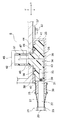
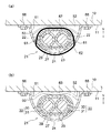
以下、図面を参照しながら実施例を説明する。図1(a)は本発明のワイヤハーネスを含む自動車の模式図、図1(b)はハーネス付属部材であるハーフパイプの前端側の斜視図、図1(c)はハーフパイプの後端側の斜視図である。また、図2は図1(a)のA−A線断面図、図3はワイヤハーネスの端末構造を示す断面図、図4(a)はハーネス本体とハーフパイプとを固定する固定構造の一例を示す断面図、図4(b)は本体保護部材の他の例を示す断面図である。 Hereinafter, embodiments will be described with reference to the drawings. 1A is a schematic view of an automobile including the wire harness of the present invention, FIG. 1B is a perspective view of a front end side of a half pipe that is a harness attachment member, and FIG. 1C is a rear end side of the half pipe. FIG. 2 is a cross-sectional view taken along line AA in FIG. 1A, FIG. 3 is a cross-sectional view showing a terminal structure of the wire harness, and FIG. 4A is an example of a fixing structure for fixing the harness body and the half pipe. FIG. 4B is a cross-sectional view showing another example of the main body protection member.
本実施例のワイヤハーネスは、ハイブリッド自動車又は電気自動車に配索されるものであって、以下ではハイブリッド自動車での例を挙げて説明をするものとする(電気自動車の場合でも本発明のワイヤハーネスの構成、構造、及び効果は基本的に同じであるものとする。 The wire harness of the present embodiment is routed to a hybrid vehicle or an electric vehicle, and will be described below by taking an example of a hybrid vehicle (even in the case of an electric vehicle, the wire harness of the present invention). The structure, structure, and effect of the above are basically the same.
図1において、引用符号1はハイブリッド自動車を示している。ハイブリッド自動車1は、エンジン2及びモータ3の二つの動力をミックスして駆動する車両であって、モータ3にはインバータ4を介してバッテリー5(電池パック)からの電力が供給されるようになっている。エンジン2、モータ3、及びインバータ4は、本実施例において前輪等がある位置のエンジンルーム6に搭載されている。また、バッテリー5は、後輪等がある車両後部7に搭載されている(エンジンルーム6の後方に存在する自動車室内8に搭載される場合もある)。
In FIG. 1,
モータ3とインバインバータ4は、モータケーブル9により接続されている。また、バッテリー5とインバータ4は、本発明に係るワイヤハーネス21により接続されている。ワイヤハーネス21は、エンジンルーム6から車両フロア10の地面側となる床下11にわたって、また、床下11から車両後部7にわたって配索されている。ワイヤハーネス21は、床下11において真っ直ぐに配策されている。
The
ここで本実施例での補足説明をすると、モータ3はモータ及びジェネレータを構成に含んでいるものとする。また、インバータ4は、インバータ及びコンバータを構成に含んでいるものとする。インバータ4は、インバータアッセンブリであって、上記インバータには、例えばエアコン・インバータやジェネレータ用インバータ、モータ用インバータが含まれるものとする。バッテリー5は、Ni−MH系やLi−ion系のものであって、モジュール化してなるものとする。尚、例えばキャパシタのような蓄電装置を使用することも可能であるものとする。バッテリー5は、ハイブリッド自動車1や電気自動車に使用可能であれば特に限定されないものとする。
Here, when supplementary explanation is given in this embodiment, it is assumed that the
ワイヤハーネス21は、インバータ4及びバッテリー5間を電気的に接続する太物の高圧電線22(高圧導電路)を含むシールド機能付きのハーネス本体23と、このシールド機能付きのハーネス本体23における車両フロア10の配索対象部分に設けられるハーフパイプ24(ハーネス付属部材)とを備えて構成されている。ハーフパイプ24は、車両フロア10の床下11に対して固定される部材となっている。また、ハーフパイプ24は、ハーネス本体23に対して付属するような部材となっている。本実施例においては、ハーネス本体23に電磁シールド機能を付加しているが、この限りでないものとする(後述する)。
The
ハーネス本体23は、複数本の高圧電線22と、この高圧電線22の一方の端末に設けられるとともに、例えばバッテリー5側(接続相手)との電気的な接続部分となる接続手段25(図3参照)と、導電性を有する金属材料にて形成される端末固定手段26(図3参照)と、複数本の高圧電線22を覆うように設けられる筒状金属箔部材27(シールド部材。図2及び図3参照)と、この筒状金属箔部材27の端末外側に設けられて加締めが施される金属製のリング状加締め部材28(図3参照)と、筒状金属箔部材27により覆われた状態の複数本の高圧電線22における保護対象部分を一括して保護する電線保護部材29(図2及び図3参照)とを備えて構成されている。尚、高圧電線22の他方の端末も上記一方の端末と同様であるものとする。
The harness
図2において、上記複数本の高圧電線22は、本実施例において二本備えられており(本数は一例であるものとする。尚、低圧電線を含んだりしてもよいものとする)、横に並んだ状態で配索されている(床下11に沿って並べるように配索されている)。高圧電線22は、太物の電線であって、中心に位置する中心導体30は、銅や銅合金やアルミニウムによって製造されている。高圧電線22は、非シールド電線であって、導電性を有する上記中心導体30と、この中心導体30の外側に設けられる被覆部31とを含んで構成されている。高圧電線22の上記一方の端末は、中心導体30が所定の長さで真っ直ぐに延びて露出するように加工されている。
In FIG. 2, the plurality of high-voltage
中心導体30に関しては、素線を撚り合わせてなる導体構造のものや、断面矩形又は丸形となる棒状の導体構造(例えば平角単心や丸単心となる導体構造)のもののいずれであってもよいものとする。また、高圧電線22に替えてバスバーを用いてもよいものとする。中心導体30には、接続手段25(図3参照)が接続されている。
The
尚、本実施例においては絶縁電線からなる高圧電線22を用いているが、これに限らず高圧のシールド電線(高圧導電路)を用いてもよいものとする。シールド電線は、中心導体と、この中心導体の外側に設けられる絶縁体と、絶縁体の外側に設けられるシールド部材と、シールド部材の外側に設けられるシースとを備えて構成されている。シールド部材は、編組又は金属箔にて形成されている。
In the present embodiment, the high-
図3において、上記接続手段25は、上記の如くバッテリー5側(接続相手)との電気的な接続部分であって、先端側が略タブ状となる端子形状に形成されている。接続手段25は、先端側に位置する電気接触部32と、中心導体30に対して例えば圧着等で接続される電線接続部33と、これら電気接触部32及び電線接続部33を繋ぐ中間部34とを有している。電気接触部32は、中間部34に対して直交するように折り曲げ形成されている。接続手段25の全体は、略L字状に曲がる形状に形成されている。接続手段25は、図中矢印Vで示す垂直方向に沿って電気的な接続が行われるようになっている。
In FIG. 3, the connection means 25 is an electrical connection portion with the
上記端末固定手段26は、複数本の高圧電線22の端末及び接続手段25をバッテリー5側の所定位置に配置固定するための部材であって、本実施例においては上記の如く導電性を有する金属材料にて形成されている。本実施例における端末固定手段26は、筐体部35と、この筐体部35に連成される筒状接続部36及び固定鍔部37とを有している。
The terminal fixing means 26 is a member for arranging and fixing the terminals of the plurality of high-voltage
筐体部35は、この上壁38に開口部分39を有している。また、内部に連通するように筒状接続部36が側壁40の位置に連成されている。側壁40とは別の側壁41には、上壁38の位置に合わせて固定鍔部37が連成されている。固定鍔部37は、ボルト42による締め付け固定を行う部分として形成されている。本実施例における端末固定手段26は、ボルト42によってバッテリー5側に固定をすることができるように形成されている。尚、特に図示しないが、固定鍔部37は少なくとも二箇所形成されている。上壁38は、バッテリー5側に接触する部分として形成されている。上壁38は、アースをする部分としての機能を有している。
The
筐体部35の底壁43は、平坦でバッテリー5側の底壁44に対して平行となるように形成されている。端末固定手段26をバッテリー5側に固定した状態においては、筒状接続部36も底壁44に対して平行となるようになっている。筒状接続部36は、底壁44が図中矢印Pで示す水平方向に沿うことから、この方向に延びるように形成されている。尚、引用符号45はバッテリー5側のコネクタを仮想線にて示している。
The
筒状接続部36は、この外側に筒状金属箔部材27を挿入することができるように形成されている。また、筒状接続部36は、リング状加締め部材28への加締めによって筒状金属箔部材27を電気的且つ機械的に接続することができるように形成されている。本実施例における筒状接続部36は、断面長円形状に形成されている。筒状接続部36は、筐体部35に連成されることから、金属製であるとともに導電性を有している。尚、筒状接続部36を公知のシールドシェルとして形成し、筐体部35に対して例えばボルト止め等の適宜固定手段で接続するようにしてもよいものとする。
The
上記筒状金属箔部材27は、導電性を有する金属箔を筒状に形成してなる部材であって、電磁波対策としての電磁シールド機能を有している。筒状金属箔部材27を構成する金属箔の一例としては、例えば銅箔が好適であるものとする(銅箔以外の公知の金属箔であっても当然によいものとする)。本実施例における筒状金属箔部材27は、金属箔の単体によりなるものであるが、強度を高める必要がある場合には、金属箔を二重や三重などにしてもよいものとする。
The cylindrical
尚、複数の層のうちの一つに金属箔を有するようにすれば、筒状金属箔部材27の強度を更に高めることができるようになるのは言うまでもない。この場合、金属箔(銅箔)に接着層を介して樹脂シートを層状に重ねることが好適であるものとする。樹脂シートに関してはPETシートが一例として挙げられるものとする。金属箔には(樹脂シートの反対側)、スズメッキを施してもよいものとする。筒状金属箔部材27は、本実施例において、ハーネス本体23に電磁シールド機能を付加するための部材として設けられているが、仮に後述するハーフパイプ24に電磁シールド機能を持たせる場合には、筒状金属箔部材27の設定は任意であるものとする。
Needless to say, if the metal foil is provided in one of the plurality of layers, the strength of the cylindrical
筒状金属箔部材27の端末部分は、リング状加締め部材28への加締めによって筒状接続部36に対し電気的且つ機械的に接続されるようになっている。
The end portion of the cylindrical
上記リング状加締め部材28は、図示しない加締め型による加締め(押し潰し)により永久変形する部材であって、例えば帯状の金属薄板を長円形状に丸めるプレス加工を経て形成されている。リング状加締め部材28は、筒状金属箔部材27の端末外側に設けられるようになっている。
The ring-shaped
リング状加締め部材28への加締めにより筒状金属箔部材27の端末部分が筒状接続部36に電気的且つ機械的に接続されると、筒状金属箔部材27に収容される複数本の高圧電線22は(被覆部31は)、底壁44に対して平行な配置となるようになっている。尚、高圧電線22としては、本実施例に限らず、キャブタイヤケーブルを用いてもよいものとする。筒状接続部36に電気的に接続された筒状金属箔部材27は、端末固定手段26を介してバッテリー5側にアースされるようになっている。
When the terminal portion of the cylindrical
高圧電線22の端末に設けられる接続手段25に関し、この接続手段25が筐体部35の内部に収容されると、絶縁性を有する樹脂材料にて形成されたハウジング46により固定されるようになっている。ハウジング46には、上壁38の開口部分39から上方へ突出するコネクタ嵌合部47が形成されており、このコネクタ嵌合部47の内部空間に接続手段25の電気接触部32が露出するようになっている。ハウジング46が形成されることにより、この部分はコネクタ48としての機能を有している。
Regarding the connection means 25 provided at the terminal of the high-
尚、ハウジング45の形成方法は特に限定されないものとする。例えば、接続手段25に樹脂製のサブハウジングを一体化させ、この後、サブハウジングと筐体部35の内面との隙間をポッティング等にて樹脂埋めするような形成方法であってもよいものとする。
In addition, the formation method of the
ハウジング46には、防水用のパッキン49が設けられている(設けるのは任意であるものとする)。
The
上記電線保護部材29は、上記の如く筒状金属箔部材27により覆われた状態の複数本の高圧電線22に対し、この保護対象部分を一括して保護する部材であって、本実施例においてはシート状のものを巻き付けるような使用形態になっている。電線保護部材29は、例えばコルゲートチューブで代替してもよいものとする。電線保護部材29の設定は任意であるものとする。
The
図1及び図2において、上記ハーフパイプ24は、本実施例において丸パイプを半割にしたものに対し、この高さ(図中矢印Vで示す垂直方向の長さ)が丸パイプの半径よりも短くなるような形状(図2参照)に形成されている。ハーフパイプ24は、本実施例において丸パイプを単に1/2に半割した形状ではないように形成されている。すなわち、低背化に配慮することができるように形成されている。ハーフパイプ24は、金属製、合成樹脂製のいずれであってもよく、本実施例においては、金属製のものとなっている。ハーフパイプ24は、この外面50側が放熱特性が良く、また、内面51側が高圧電線22に対して吸熱特性が良い材質が採用されている(材質は特に限定されないものとする。好ましい一例に関しては後述する)。ハーフパイプ24は、外部への放熱、外部からの遮熱、電線保護等の機能を有するものとなっている。ハーフパイプ24の内面51には、ハーネス本体23がこの自重によって接触するようになっている(高圧電線22が間接的に接触するようになっている)。ハーフパイプ24は、本実施例において、押し出し又はプレスにより形成されている。
1 and 2, the
ハーフパイプ24は、車両フロア10の床下11に対向する側の開口52と、ハーネス本体23の引き出し側の開口53、53とを連続して開口させるような略軒樋形状に形成されている(樋にはいくつかの形状があり、その一種である軒樋は筒を半割したような形状である)。ハーフパイプ24は、真っ直ぐに延びるように形成されている。
The
ハーフパイプ24の両端となる開口53、53の縁部には、エッジ部分を覆うようにエッジ被覆部材54が設けられている。エッジ被覆部材54は、ハーネス本体23の損傷を防止する部材として設けられている(エッジが生じないようであれば、エッジ被覆部材54を設けなくてもよいものとする)。
ハーフパイプ24は、開口52を床下11に対向させるようにして固定されるような固定構造になっており、固定手段としては、例えば開口52の位置に合わせて複数設けられるブラケット部55が一例として挙げられるものとする。ブラケット部55は、例えば溶接により固定されており、ボルト止め用の貫通孔56を有している。尚、ボルト止めに限らずクリップで固定することであってもよいものとする。他の固定手段としては、ハーフパイプ24の外面50に係合してこれを保持することができるような逆Ω形状のクランプや、バンド等であってもよいものとする。
The
ハーフパイプ24は、特に限定するものでないが、収容状態にあるハーネス本体23を固定することができるように形成されている。具体的には、専用のクランプや汎用のバンドクランプ等で固定をすることができるように、例えば穴等が複数箇所形成されている(一例としては、図4(a)に示す如くハーフパイプ24に一対の穴61、61を複数形成し、各箇所の穴61、61に既知の結束バンド62を通してハーネス本体23を固定することが挙げられる)。このようなハーフパイプ24には、上記穴の他に水抜き穴も形成されている(図示省略。水抜き穴の形成は任意であるものとする)。
The
ここで、ハーフパイプ24を金属製とする場合の補足説明をする。ハーフパイプ24を金属製にすると、樹脂製よりも保護性能を高めたりすることができるのは言うまでもない。金属製にするにあたり、材質としては保護性能の面や軽量化の面からアルミニウムが一例として挙げられるものとする。また、保護性能の面や耐候性の面からステンレスも好適な一例として挙げられるものとする。ここでは、アルミニウム製であるものとする。
Here, a supplementary explanation will be given when the
尚、ハーフパイプ24は、本実施例において断面が円弧形状であるが、この限りでないものとする。例えば断面コ字状となる形状であってもよいものとする。断面コ字状となる形状の場合は、ハーネス本体23に対する接触面積を稼ぐことができる等の利点を有している。また、ハーフパイプ24は、本実施例において真っ直ぐに延びる形状であるが、この限りでないものとする。例えば適宜位置で曲げ加工を施して経路を変えるようにしてもよいものとする。
The
図2において、引用符号57は本体保護部材を示している。この本体保護部材57は、ハーネス本体23と車両フロア10の床下11との間に介在する部材であって、仮に床下11にスポットバリ等が生じる場合、ハーネス本体23を保護して損傷を防止することができるようになっている。本体保護部材57は、ハーフパイプ24の全長にわたって、或いは上記スポットバリ等の発生可能性のある場所に応じて設定されている(本体保護部材57の設定は任意であるものとする)。本体保護部材57は、仮想線で示すような形状の他に、ハーネス本体23をハーフパイプ24の内面51に押しつけることができるような図4(b)に示すバネ性のある形状に形成してもよいものとする。図4(b)において、本体保護部材63は、ハーネス本体23を押圧するバネ性を有している(形状は一例であるものとする)。このようにハーネス本体23をハーフパイプ24の内面51に押し付ければ、ハーネス本体23に生じる熱を確実にハーフパイプ24に伝えて温度を下げることができるという利点を有している。本体保護部材63は、車両走行時や振動発生時において、ハーネス本体23をハーフパイプ24の内面51に押し付けることができることから、安定した放熱効果等を得られるという利点を有している。尚、本体保護部材57は、コルゲートチューブ(図示省略)等のハーネス本体23を覆うことができるような部材で代替してもよいものとする。
In FIG. 2,
以上、図1ないし図3を参照しながら説明してきたように、略軒樋形状のハーフパイプ24にハーネス本体23を収容し、そして、このハーフパイプ24を車両フロア10の床下11に固定すると、ハーネス本体23は床下11に沿って配索される。ハーネス本体23の収容は、ハーフパイプ24が略軒樋形状であり、三方が連続して開口するような形状であることから、従来のような通線作業をすることなく簡単に行うことができるようになる。また、ハーフパイプ24は略軒樋形状であることから、予めハーネス本体23を通線するというような作業はなく、結果、ワイヤハーネス21の製造手順に自由度を持たせることができるようになる。
As described above with reference to FIGS. 1 to 3, when the
ハーフパイプ24は、例えば同じようなサイズの丸パイプと比較した場合、少なくとも車両フロア10の床下11に対向する開口52の側の分だけ丸パイプよりも軽量化を図ることができるようになる。また、上記の分だけ丸パイプよりも使用材料を低減することができるようになる。従来のパイプと比べると、約50%減を実現することができるようになる。
For example, when compared with a round pipe of the same size, the
この他、ハーフパイプ24は、後工程で曲げ加工することが可能なものであることから、金型費用を削減することができるようになる。また、曲げを変えることにより、別の車両へも展開することが可能で汎用性を高めることができるようになる。さらに、設計変更にも素早く対応することができるようになる。
In addition, since the
ハーフパイプ24は、この内面51にハーネス本体23を接触(密着)させることから、ハーネス本体23に生じた熱をハーフパイプ24を介して車両フロア10の床下11側へ伝えることができるようになる。また、ハーネス本体23に生じた熱をハーフパイプ24の外面50から放熱することができるようになる。すなわち、ハーフパイプ24の内面51に接触(密着)させることで、ハーネス本体23の温度を下げることができるようになる。
Since the
ハーフパイプ24は、ハーネス本体23における車両フロア10の配索対象部分に設けるだけの長さであることから、梱包スペースを取らないようにすることができるようになる。
Since the
本発明は本発明の主旨を変えない範囲で種々変更実施可能なことは勿論である。 It goes without saying that the present invention can be variously modified without departing from the spirit of the present invention.
上記説明では、ハーフパイプ24に対しブラケット部55が別体で、例えば溶接により固定されるとしているが、これに限らず図5に示す如くの一体形状にしてもよいものとする。図5の場合、押し出し成形によりブラケット部64がハーフパイプ24のパイプ本体65に一体になっている。ブラケット部64は、開口52の縁部全体にわたって一体化するように形成されている。
In the above description, the
1…ハイブリッド自動車
2…エンジン
3…モータ
4…インバータ
5…バッテリー
6…エンジンルーム
7…車両後部
8…自動車室内
9…モータケーブル
10…車両フロア
11…床下
21…ワイヤハーネス
22…高圧電線(高圧導電路)
23…ハーネス本体
24…ハーフパイプ(ハーネス付属部材)
25…接続手段
26…端末固定手段
27…筒状金属箔部材(シールド部材)
28…リング状加締め部材
29…電線保護部材
30…中心導体
31…被覆部
32…電気接触部
33…電線接続部
34…中間部
35…筐体部
36…筒状接続部
37…固定鍔部
38…上壁
39…開口部分
40、41…側壁
42…ボルト
43、44…底壁
45…コネクタ
46…ハウジング
47…コネクタ嵌合部
48…コネクタ
49…パッキン
50…外面
51…内面
52、53…開口
54…エッジ被覆部材
55…ブラケット部
56…貫通孔
57…本体保護部材
DESCRIPTION OF
23 ...
25 ... Connection means 26 ... Terminal fixing means 27 ... Cylindrical metal foil member (shield member)
DESCRIPTION OF
Claims (3)
ことを特徴とするワイヤハーネス。 A harness body including a plurality of high-voltage conductive paths, and a harness accessory member provided at a wiring target portion of the vehicle floor in the harness body and fixed to the vehicle floor; A wire harness characterized by being formed in a substantially eaves-like shape that continuously opens a side facing a vehicle floor and a drawing side of the harness body.
前記ハーネス本体と前記車両フロアとの間に介在する本体保護部材を備える
ことを特徴とするワイヤハーネス。 The wire harness according to claim 1,
A wire harness comprising a main body protection member interposed between the harness main body and the vehicle floor.
前記ハーネス本体を前記ハーネス付属部材の内面に直接又は間接的に接触させるように収容する
ことを特徴とするワイヤハーネス。 In the wire harness according to claim 1 or claim 2,
The wire harness is accommodated so that the harness main body is directly or indirectly brought into contact with the inner surface of the harness accessory member.
Priority Applications (5)
| Application Number | Priority Date | Filing Date | Title |
|---|---|---|---|
| JP2010059108A JP5393548B2 (en) | 2010-03-16 | 2010-03-16 | Wire harness |
| PCT/JP2011/052510 WO2011114801A1 (en) | 2010-03-16 | 2011-02-07 | Wire harness |
| EP11755991.4A EP2549601B1 (en) | 2010-03-16 | 2011-02-07 | Wire harness |
| US13/634,644 US9045092B2 (en) | 2010-03-16 | 2011-02-07 | Wiring harness |
| CN201180022065.0A CN102884691B (en) | 2010-03-16 | 2011-02-07 | Wire harness |
Applications Claiming Priority (1)
| Application Number | Priority Date | Filing Date | Title |
|---|---|---|---|
| JP2010059108A JP5393548B2 (en) | 2010-03-16 | 2010-03-16 | Wire harness |
Publications (2)
| Publication Number | Publication Date |
|---|---|
| JP2011192578A true JP2011192578A (en) | 2011-09-29 |
| JP5393548B2 JP5393548B2 (en) | 2014-01-22 |
Family
ID=44648908
Family Applications (1)
| Application Number | Title | Priority Date | Filing Date |
|---|---|---|---|
| JP2010059108A Expired - Fee Related JP5393548B2 (en) | 2010-03-16 | 2010-03-16 | Wire harness |
Country Status (5)
| Country | Link |
|---|---|
| US (1) | US9045092B2 (en) |
| EP (1) | EP2549601B1 (en) |
| JP (1) | JP5393548B2 (en) |
| CN (1) | CN102884691B (en) |
| WO (1) | WO2011114801A1 (en) |
Cited By (7)
| Publication number | Priority date | Publication date | Assignee | Title |
|---|---|---|---|---|
| WO2014030703A1 (en) * | 2012-08-22 | 2014-02-27 | 矢崎総業株式会社 | Wire harness |
| US10103527B2 (en) | 2016-07-05 | 2018-10-16 | Mitsubishi Electric Corporation | Shielded harness including molded body and fixing member |
| JP2019176617A (en) * | 2018-03-28 | 2019-10-10 | 株式会社オートネットワーク技術研究所 | Conductive path |
| JP2019216533A (en) * | 2018-06-12 | 2019-12-19 | 株式会社オートネットワーク技術研究所 | Conducting path |
| WO2020170541A1 (en) * | 2019-02-22 | 2020-08-27 | 株式会社オートネットワーク技術研究所 | Electromagnetic shield member and wire harness |
| JP2022089844A (en) * | 2019-03-11 | 2022-06-16 | 株式会社オートネットワーク技術研究所 | Electromagnetic shield member and wire harness |
| JP2022115894A (en) * | 2019-02-22 | 2022-08-09 | 株式会社オートネットワーク技術研究所 | Electromagnetic shielding materials and wire harnesses |
Families Citing this family (12)
| Publication number | Priority date | Publication date | Assignee | Title |
|---|---|---|---|---|
| JP2013229408A (en) * | 2012-04-25 | 2013-11-07 | Auto Network Gijutsu Kenkyusho:Kk | Wiring harness |
| EP3109097B1 (en) * | 2015-06-26 | 2018-08-29 | Nexans | Device for holding a wiring harness |
| JP6646874B2 (en) * | 2016-06-08 | 2020-02-14 | 住友電装株式会社 | Protector and wire harness |
| DE102017111525A1 (en) | 2017-05-26 | 2019-01-03 | Bombardier Transportation Gmbh | Vehicle with at least one duct device and method for equipping a vehicle with a duct device |
| CN107275902A (en) * | 2017-07-25 | 2017-10-20 | 上饶市达淋新材料有限公司 | Flat wire harness is used in electrical equipment connection in automobile |
| JP2019089398A (en) * | 2017-11-13 | 2019-06-13 | 矢崎総業株式会社 | Electric wire arrangement structure and vehicle circuit body |
| JP6955219B2 (en) * | 2018-03-30 | 2021-10-27 | 住友電装株式会社 | Wire harness |
| JP6624234B2 (en) * | 2018-05-10 | 2019-12-25 | 株式会社オートネットワーク技術研究所 | Wiring member mounting structure |
| JP6984566B2 (en) * | 2018-08-24 | 2021-12-22 | 住友電装株式会社 | Holder and wire harness |
| JP7010199B2 (en) * | 2018-12-03 | 2022-01-26 | 株式会社オートネットワーク技術研究所 | Wire harness and exterior parts |
| CN109703489A (en) * | 2018-12-24 | 2019-05-03 | 芜湖尚唯汽车饰件有限公司 | A kind of trim panel with card line function |
| JP7261204B6 (en) * | 2020-07-29 | 2023-05-10 | 矢崎総業株式会社 | Shielded wire and wire harness |
Citations (4)
| Publication number | Priority date | Publication date | Assignee | Title |
|---|---|---|---|---|
| JPH0238798A (en) * | 1988-07-27 | 1990-02-08 | Suzuki Motor Co Ltd | Protective structure for vehicular harness, tube, or the like |
| JP2002176716A (en) * | 2000-12-11 | 2002-06-21 | Yazaki Corp | Wiring harness protector |
| JP2009142060A (en) * | 2007-12-06 | 2009-06-25 | Yazaki Corp | Shield member |
| JP2010012868A (en) * | 2008-07-02 | 2010-01-21 | Yazaki Corp | Wire harness |
Family Cites Families (6)
| Publication number | Priority date | Publication date | Assignee | Title |
|---|---|---|---|---|
| JP3909763B2 (en) | 2002-11-20 | 2007-04-25 | 株式会社オートネットワーク技術研究所 | Vehicle conductive path with shield function |
| CN100544144C (en) * | 2002-12-19 | 2009-09-23 | 本田技研工业株式会社 | Comprise the bundle conductor group of bundle conductor and retainer thereof and the method for this bundle conductor group of manufacturing |
| JP4146316B2 (en) * | 2003-09-02 | 2008-09-10 | 矢崎総業株式会社 | Protector |
| JP2005160222A (en) * | 2003-11-26 | 2005-06-16 | Yazaki Corp | Lock structure of protector and wiring harness |
| JP5272510B2 (en) * | 2008-05-13 | 2013-08-28 | 株式会社オートネットワーク技術研究所 | Wire harness with protective material for vehicle and wiring structure of wire harness for vehicle |
| JP5917806B2 (en) * | 2011-01-21 | 2016-05-18 | 矢崎総業株式会社 | Method for manufacturing protector and method for manufacturing wire harness |
-
2010
- 2010-03-16 JP JP2010059108A patent/JP5393548B2/en not_active Expired - Fee Related
-
2011
- 2011-02-07 WO PCT/JP2011/052510 patent/WO2011114801A1/en active Application Filing
- 2011-02-07 EP EP11755991.4A patent/EP2549601B1/en not_active Not-in-force
- 2011-02-07 US US13/634,644 patent/US9045092B2/en not_active Expired - Fee Related
- 2011-02-07 CN CN201180022065.0A patent/CN102884691B/en not_active Expired - Fee Related
Patent Citations (4)
| Publication number | Priority date | Publication date | Assignee | Title |
|---|---|---|---|---|
| JPH0238798A (en) * | 1988-07-27 | 1990-02-08 | Suzuki Motor Co Ltd | Protective structure for vehicular harness, tube, or the like |
| JP2002176716A (en) * | 2000-12-11 | 2002-06-21 | Yazaki Corp | Wiring harness protector |
| JP2009142060A (en) * | 2007-12-06 | 2009-06-25 | Yazaki Corp | Shield member |
| JP2010012868A (en) * | 2008-07-02 | 2010-01-21 | Yazaki Corp | Wire harness |
Cited By (14)
| Publication number | Priority date | Publication date | Assignee | Title |
|---|---|---|---|---|
| WO2014030703A1 (en) * | 2012-08-22 | 2014-02-27 | 矢崎総業株式会社 | Wire harness |
| US10103527B2 (en) | 2016-07-05 | 2018-10-16 | Mitsubishi Electric Corporation | Shielded harness including molded body and fixing member |
| JP2019176617A (en) * | 2018-03-28 | 2019-10-10 | 株式会社オートネットワーク技術研究所 | Conductive path |
| JP2019216533A (en) * | 2018-06-12 | 2019-12-19 | 株式会社オートネットワーク技術研究所 | Conducting path |
| WO2019239862A1 (en) * | 2018-06-12 | 2019-12-19 | 株式会社オートネットワーク技術研究所 | Electroconductive path |
| US11273773B2 (en) | 2018-06-12 | 2022-03-15 | Autonetworks Technologies. Ltd. | Conduction path |
| JP2020137328A (en) * | 2019-02-22 | 2020-08-31 | 株式会社オートネットワーク技術研究所 | Electromagnetic shield member and wire harness |
| WO2020170541A1 (en) * | 2019-02-22 | 2020-08-27 | 株式会社オートネットワーク技術研究所 | Electromagnetic shield member and wire harness |
| JP7067507B2 (en) | 2019-02-22 | 2022-05-16 | 株式会社オートネットワーク技術研究所 | Electromagnetic shield member and wire harness |
| JP2022115894A (en) * | 2019-02-22 | 2022-08-09 | 株式会社オートネットワーク技術研究所 | Electromagnetic shielding materials and wire harnesses |
| JP7239906B2 (en) | 2019-02-22 | 2023-03-15 | 株式会社オートネットワーク技術研究所 | Electromagnetic shielding materials and wire harnesses |
| US11700717B2 (en) | 2019-02-22 | 2023-07-11 | Autonetworks Technologies, Ltd. | Electromagnetic shield member and wire harness |
| JP2022089844A (en) * | 2019-03-11 | 2022-06-16 | 株式会社オートネットワーク技術研究所 | Electromagnetic shield member and wire harness |
| JP7302695B2 (en) | 2019-03-11 | 2023-07-04 | 株式会社オートネットワーク技術研究所 | Electromagnetic shielding materials and wire harnesses |
Also Published As
| Publication number | Publication date |
|---|---|
| EP2549601A1 (en) | 2013-01-23 |
| JP5393548B2 (en) | 2014-01-22 |
| CN102884691B (en) | 2015-08-12 |
| EP2549601A4 (en) | 2014-04-30 |
| US9045092B2 (en) | 2015-06-02 |
| CN102884691A (en) | 2013-01-16 |
| WO2011114801A1 (en) | 2011-09-22 |
| US20130008710A1 (en) | 2013-01-10 |
| EP2549601B1 (en) | 2018-04-11 |
Similar Documents
| Publication | Publication Date | Title |
|---|---|---|
| JP5393548B2 (en) | Wire harness | |
| JP5576157B2 (en) | Wire harness and manufacturing method thereof | |
| JP5491224B2 (en) | Wire harness | |
| JP5572372B2 (en) | Wire harness wiring structure and wire harness | |
| JP5566715B2 (en) | Caulking connection structure | |
| JP5654306B2 (en) | Conductive path connection structure | |
| JP5740146B2 (en) | Wire harness | |
| JP5566716B2 (en) | Wire harness | |
| JP5864228B2 (en) | High voltage conductive path and wire harness | |
| US9412491B2 (en) | Wire harness | |
| WO2014014096A1 (en) | Wire harness | |
| JP2018133837A (en) | Structure of connection of conducting paths and wiring harness | |
| JP2012059395A (en) | Conducting path structure and wire harness | |
| US9252575B2 (en) | High-voltage conduction path and wiring harness | |
| JP5781289B2 (en) | Wire harness wiring structure |
Legal Events
| Date | Code | Title | Description |
|---|---|---|---|
| A621 | Written request for application examination |
Free format text: JAPANESE INTERMEDIATE CODE: A621 Effective date: 20130215 |
|
| A131 | Notification of reasons for refusal |
Free format text: JAPANESE INTERMEDIATE CODE: A131 Effective date: 20130716 |
|
| A521 | Request for written amendment filed |
Free format text: JAPANESE INTERMEDIATE CODE: A523 Effective date: 20130917 |
|
| TRDD | Decision of grant or rejection written | ||
| A01 | Written decision to grant a patent or to grant a registration (utility model) |
Free format text: JAPANESE INTERMEDIATE CODE: A01 Effective date: 20131008 |
|
| A61 | First payment of annual fees (during grant procedure) |
Free format text: JAPANESE INTERMEDIATE CODE: A61 Effective date: 20131015 |
|
| R150 | Certificate of patent or registration of utility model |
Ref document number: 5393548 Country of ref document: JP Free format text: JAPANESE INTERMEDIATE CODE: R150 Free format text: JAPANESE INTERMEDIATE CODE: R150 |
|
| R250 | Receipt of annual fees |
Free format text: JAPANESE INTERMEDIATE CODE: R250 |
|
| R250 | Receipt of annual fees |
Free format text: JAPANESE INTERMEDIATE CODE: R250 |
|
| R250 | Receipt of annual fees |
Free format text: JAPANESE INTERMEDIATE CODE: R250 |
|
| R250 | Receipt of annual fees |
Free format text: JAPANESE INTERMEDIATE CODE: R250 |
|
| R250 | Receipt of annual fees |
Free format text: JAPANESE INTERMEDIATE CODE: R250 |
|
| R250 | Receipt of annual fees |
Free format text: JAPANESE INTERMEDIATE CODE: R250 |
|
| LAPS | Cancellation because of no payment of annual fees |