EP2549601A1 - Wire harness - Google Patents
Wire harness Download PDFInfo
- Publication number
- EP2549601A1 EP2549601A1 EP11755991A EP11755991A EP2549601A1 EP 2549601 A1 EP2549601 A1 EP 2549601A1 EP 11755991 A EP11755991 A EP 11755991A EP 11755991 A EP11755991 A EP 11755991A EP 2549601 A1 EP2549601 A1 EP 2549601A1
- Authority
- EP
- European Patent Office
- Prior art keywords
- harness
- main body
- half pipe
- high voltage
- vehicle floor
- Prior art date
- Legal status (The legal status is an assumption and is not a legal conclusion. Google has not performed a legal analysis and makes no representation as to the accuracy of the status listed.)
- Granted
Links
- 230000001681 protective effect Effects 0.000 claims description 27
- 238000004519 manufacturing process Methods 0.000 abstract description 6
- 239000011888 foil Substances 0.000 description 29
- 239000004020 conductor Substances 0.000 description 11
- 229920005989 resin Polymers 0.000 description 6
- 239000011347 resin Substances 0.000 description 6
- 238000003780 insertion Methods 0.000 description 5
- 230000037431 insertion Effects 0.000 description 5
- 229910052751 metal Inorganic materials 0.000 description 5
- 239000002184 metal Substances 0.000 description 5
- 230000000694 effects Effects 0.000 description 4
- 239000000463 material Substances 0.000 description 4
- 229910052782 aluminium Inorganic materials 0.000 description 3
- XAGFODPZIPBFFR-UHFFFAOYSA-N aluminium Chemical compound [Al] XAGFODPZIPBFFR-UHFFFAOYSA-N 0.000 description 3
- 239000007769 metal material Substances 0.000 description 3
- 238000001125 extrusion Methods 0.000 description 2
- 239000012212 insulator Substances 0.000 description 2
- 239000010410 layer Substances 0.000 description 2
- 238000000465 moulding Methods 0.000 description 2
- 238000012856 packing Methods 0.000 description 2
- 230000005855 radiation Effects 0.000 description 2
- 238000003466 welding Methods 0.000 description 2
- 229910018095 Ni-MH Inorganic materials 0.000 description 1
- 229910018477 Ni—MH Inorganic materials 0.000 description 1
- ATJFFYVFTNAWJD-UHFFFAOYSA-N Tin Chemical compound [Sn] ATJFFYVFTNAWJD-UHFFFAOYSA-N 0.000 description 1
- 238000010521 absorption reaction Methods 0.000 description 1
- 239000012790 adhesive layer Substances 0.000 description 1
- 229910045601 alloy Inorganic materials 0.000 description 1
- 239000000956 alloy Substances 0.000 description 1
- 238000009954 braiding Methods 0.000 description 1
- 239000003990 capacitor Substances 0.000 description 1
- 238000005520 cutting process Methods 0.000 description 1
- 238000013461 design Methods 0.000 description 1
- 229910001416 lithium ion Inorganic materials 0.000 description 1
- 238000000034 method Methods 0.000 description 1
- 238000012986 modification Methods 0.000 description 1
- 230000004048 modification Effects 0.000 description 1
- 238000004806 packaging method and process Methods 0.000 description 1
- 238000004382 potting Methods 0.000 description 1
- 238000003825 pressing Methods 0.000 description 1
- 230000000191 radiation effect Effects 0.000 description 1
- 239000002356 single layer Substances 0.000 description 1
- 239000010935 stainless steel Substances 0.000 description 1
- 229910001220 stainless steel Inorganic materials 0.000 description 1
- 238000003860 storage Methods 0.000 description 1
- 229920003002 synthetic resin Polymers 0.000 description 1
- 239000000057 synthetic resin Substances 0.000 description 1
Images


Classifications
-
- B—PERFORMING OPERATIONS; TRANSPORTING
- B60—VEHICLES IN GENERAL
- B60R—VEHICLES, VEHICLE FITTINGS, OR VEHICLE PARTS, NOT OTHERWISE PROVIDED FOR
- B60R16/00—Electric or fluid circuits specially adapted for vehicles and not otherwise provided for; Arrangement of elements of electric or fluid circuits specially adapted for vehicles and not otherwise provided for
- B60R16/02—Electric or fluid circuits specially adapted for vehicles and not otherwise provided for; Arrangement of elements of electric or fluid circuits specially adapted for vehicles and not otherwise provided for electric constitutive elements
- B60R16/0207—Wire harnesses
- B60R16/0215—Protecting, fastening and routing means therefor
-
- H—ELECTRICITY
- H02—GENERATION; CONVERSION OR DISTRIBUTION OF ELECTRIC POWER
- H02G—INSTALLATION OF ELECTRIC CABLES OR LINES, OR OF COMBINED OPTICAL AND ELECTRIC CABLES OR LINES
- H02G3/00—Installations of electric cables or lines or protective tubing therefor in or on buildings, equivalent structures or vehicles
- H02G3/30—Installations of cables or lines on walls, floors or ceilings
- H02G3/32—Installations of cables or lines on walls, floors or ceilings using mounting clamps
-
- H—ELECTRICITY
- H02—GENERATION; CONVERSION OR DISTRIBUTION OF ELECTRIC POWER
- H02G—INSTALLATION OF ELECTRIC CABLES OR LINES, OR OF COMBINED OPTICAL AND ELECTRIC CABLES OR LINES
- H02G3/00—Installations of electric cables or lines or protective tubing therefor in or on buildings, equivalent structures or vehicles
- H02G3/02—Details
- H02G3/04—Protective tubing or conduits, e.g. cable ladders or cable troughs
- H02G3/0462—Tubings, i.e. having a closed section
- H02G3/0468—Corrugated
-
- H—ELECTRICITY
- H02—GENERATION; CONVERSION OR DISTRIBUTION OF ELECTRIC POWER
- H02G—INSTALLATION OF ELECTRIC CABLES OR LINES, OR OF COMBINED OPTICAL AND ELECTRIC CABLES OR LINES
- H02G3/00—Installations of electric cables or lines or protective tubing therefor in or on buildings, equivalent structures or vehicles
- H02G3/02—Details
- H02G3/04—Protective tubing or conduits, e.g. cable ladders or cable troughs
- H02G3/0462—Tubings, i.e. having a closed section
- H02G3/0487—Tubings, i.e. having a closed section with a non-circular cross-section
Definitions
- This invention relates to a wiring harness configured to be cabled in a vehicle.
- a wiring harness disclosed in below-listed PTL 1 includes: a plurality of non-shielded electric wires; and a metallic shield pipe.
- the non-shied electric wires are inserted into the shield pipe so as to attain electromagnetic shield and to be protected against outside influences.
- an object of the present invention is to provide a wiring harness able to increase flexibility of a production process, to improve workability, and to save weight.
- a wiring harness including:
- the harness main body when the harness main body is received in the substantially roof gutter shaped harness attachment member, and the harness attachment member is fixed to the vehicle floor, the harness main body is cabled along the vehicle floor. Because the harness attachment member is the substantially roof gutter shape, and three sides of the harness attachment member are continuously opened, the harness main body is easily received in the harness attachment member without insertion of the harness main body to the harness attachment member. Further, because the harness attachment member is formed in the substantially roof gutter shape, flexibility of a production process of the wiring harness is increased. Compared to a pipe having the same size, the harness attachment member saves more weight than the pipe at least due to an opening side opposite to the vehicle floor.
- the high voltage electrically conductive path is a high voltage electric wire, a bus bar, or the like.
- the wiring harness as described in the first aspect further including:
- the main body protective member prevents the harness main body from being damaged.
- the wiring harness as described in the first aspect or the second aspect, wherein the harness main body is received in a manner to be abutted on an inner wall of the harness attachment member directly or indirectly.
- heat generated in the harness main body is transmitted to the vehicle floor side via the harness attachment member. Further, the heat generated in the harness main body is radiated from an outer wall of the harness attachment member.
- the harness attachment member when the harness attachment member is included, and formed in the substantially roof gutter shape, the flexibility of the production process of the wiring harness is increased compared to the conventional wiring harness. Further, by forming the harness attachment member in the substantially roof gutter shape, the workability is improved, and the weight is saved compared to the conventional wiring harness.
- the harness main body is prevented from being damaged.
- the wiring harness has good heat radiation property.
- a wiring harness includes: a harness main body having a high voltage electrically conductive paths; and a harness attachment member.
- the harness attachment member is formed in a substantially roof gutter shape.
- the harness attachment member is provided on a cabling target portion of a vehicle floor where the harness main body is cabled and fixed to the vehicle floor with this substantially roof gutter shape.
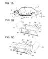
- Fig. 1A is a schematic vie showing a vehicle having a wiring harness according to the present invention.
- Fig. 1B is a perspective view showing a front end side of a half pipe as a harness attachment member.
- Fig. 1C is a perspective view showing a rear end of the half pipe.
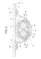
- Fig. 2 is a sectional view taken on line A - A of Fig. 1A .
- Fig. 3 is a sectional view showing an end structure of the wiring harness.
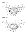
- Fig. 4A is a sectional view showing an example of a fixing structure fixing a harness main body and the half pipe.
- Fig. 4B is a sectional view showing the other example of a main body protective member.
- the wiring harness of this embodiment is cabled in a hybrid vehicle or an electric vehicle, and hereinafter will be explained with an example of the hybrid vehicle. (In a case of the electric vehicle, a configuration, a structure, and an effect of the wiring harness according to the present invention is basically the same.)
- reference sign 1 denotes the hybrid vehicle.
- the hybrid vehicle 1 is driven by mixing two powers of an engine 2 and a motor 3. Electric power from a battery 5 (battery pack) is supplied to the motor 3 via an inverter 4. in this embodiment, the engine 2, the motor 3, and the inverter 4 are mounted on an engine room 6 where a front wheel is positioned. Further, the battery 5 is mounted on a vehicle rear side 7 where a rear wheel is positioned. (The battery may be mounted on a vehicle interior 8 at a rear side of the engine room 6.)
- the motor 3 and the inverter 4 are connected to each other with a motor cable 9. Further, the battery 5 and the inverter 4 are connected to each other with a wiring harness 21 according to the present invention.
- the wiring harness 21 is cabled from the engine room 6 to an underfloor 11 as a ground side of a vehicle floor 10, and cabled from the underfloor 11 to the vehicle rear side 7.
- the wiring harness 21 is cabled straight in the underfloor 11.
- the motor 3 includes: a motor and a generator.
- the inverter 4 includes: an inverter and converter.
- the inverter 4 is an inverter assembly, and includes, for example, an air conditioner inverter, a generator inverter, and a motor inverter.
- the battery 5 is Ni-MH or Li-ion and not modularized. Incidentally, for example, an electrical storage device such as capacitor can also be used. The battery 5 is not limited as long as it can be used in the hybrid vehicle 1 or the electric vehicle.
- the wiring harness 21 includes: a shielded harness main boy 23 having thick high voltage electric wires 22 (high voltage electrically conductive paths) electrically connecting the inverter 4 and the battery 5; and a half pipe 24 (harness attachment member) provided on a cabling target portion of the vehicle floor 10 where the harness main body 23 is cabled.
- the half pipe 24 is fixed to the underfloor 11 of the vehicle floor 10. Further, the half pipe 24 is an attachment of the harness main body 23.
- the harness main body 23 is electromagnetic shielded.
- the present invention is not limited to this (described later).
- the harness main body 23 includes: a plurality of high voltage electric wires 22 as high voltage electrically conductive paths; a connecting means 25 (see Fig. 3 ) provided on one end of the high voltage electric wire 22 and electrically connecting to, for example, battery 5; an end fixing means 26 (see Fig. 3 ) made of conductive metallic material; a tubular metallic foil member 27 (shield member, see Figs. 2 and 3 ) covering the high voltage electric wires 22; a metallic ring-shaped swaging member 28 (see Fig. 3 ) provided outside of an end of the tubular metallic foil member 27 and swaged; and an electric wire protective member 29 (see Figs. 2 and 3 ) collectively protecting a protective target portion of the high voltage electric wires 22 covered by the tubular metallic foil member 27.
- the other end of the high voltage electric wire 22 is formed similar to the one end of the high voltage electric wire 22.
- the number of the high voltage electric wires 22 is two in this embodiment.
- the number of the high voltage electric wires 22 is illustrative. Incidentally, a low voltage electric wire may be included.
- the high voltage electric wires 22 are arranged horizontally (cabled along the underfloor 11).
- the high voltage electric wire 22 is a thick electric wire, and a center conductor 30 positioned in the center of the high voltage electric wire 22 is made of cupper, cupper alloy, or aluminum.
- the high voltage electric wire 22 is a non-shielded electric wire, and composed of the conductive center conductor 30 and a cover 31 provided outside of the center conductor 30.
- the one end of the high voltage electric wire 22 is processed so that the center conductor 30 is extended straight and exposed in a specific length.
- the center conductor 30 may be formed by braiding element wires or made of a bar-shaped conductor having a rectangular section or a circular section (for example, straight angle single core, or a circular single core). Further, a bus bar may be used instead of the high voltage electric wire 22.
- the connecting means 25 (see Fig. 3 ) is connected to the center conductor 30.
- the high voltage electric wire 22 made of an insulated wire is used.
- a high voltage shielded electric wire (high voltage electrically conductive path) may be used.
- the shielded electric wire includes: a center conductor; an insulator provided outside of the center conductor; a shield member provided outside of the insulator; and a sheath provided outside of the shield member.
- the shield member is made of a braided wire or a metallic foil.
- the connecting means 25 is an electrically connecting portion with the battery 5 and formed in a substantially tab shape at a tip thereof.
- the connecting means 25 includes: an electric contact portion 32 positioned at a tip thereof; a wire connecting portion 33 connected to the center conductor 30 by, for example, pressure bonding; and a middle portion 34 connecting the electric contact portion 32 and the wire connecting portion 33.
- the electric contact portion 32 is folded so as to be perpendicular to the middle portion 34.
- a whole of the connecting means 25 is formed in a substantially L-shape.
- the connecting means 25 is electrically connected along a vertical direction shown by an arrow V in Fig. 3 .
- the end fixing means 26 arranges and fixes the high voltage electric wires 22 and the connecting means 25 to a specific position in a battery 5 side, and in this embodiment, made of conductive metallic material.
- the end fixing means 26 in this embodiment includes: a chassis 35; and a tubular connecting portion 36 and a fixing flange 37 continued to the chassis 35.
- An opening 39 is provided on a top wall 38 of the chassis 35.
- the tubular connecting portion 36 is continued to a sidewall 40 so as to communicate with an inside.
- a sidewall 41 other than the sidewall 40 is continued to the fixing flange 37 at a position of the top wall 38.
- the fixing flange 37 is fastened and fixed by a bolt 42.
- the end fixing means 26 in this embodiment is fixed to the battery 5 side with the bolt 42.
- at least two fixing flanges 37 are formed.
- the top wall 38 is abutted on the battery 5 side.
- the top wall 38 works as an electrical ground.
- a bottom wall 43 of the chassis 35 is formed flat and parallel to a bottom wall 44 of the battery 5 side.
- the tubular connecting portion 36 is also arranged parallel to the bottom wall 44. Because the bottom wall 44 is extended along a horizontal direction denoted by an arrow P in Fig. 3 , the tubular connecting portion 36 is extended in this direction.
- reference sign 45 denotes a connector of the battery 5 side by a virtual line.
- the tubular metallic foil member 27 is inserted over an outside of the tubular connecting portion 36. Further, the tubular connecting portion 36 is electrically and mechanically connected to the tubular metallic foil member 27 by swaging with the ring-shaped swaging member 28. In this embodiment, the tubular connecting portion 36 is formed in a oblong sectional shape. Because the tubular connecting portion 36 is continued to the chassis 35, the tubular connecting portion 36 is conductive and metallic. Incidentally, the tubular connecting portion 36 may be formed as a well-known shield shell, and connected to the chassis 35 with a proper fixing means such as a bolt.
- the tubular metallic foil member 27 is made of conductive metallic foil, formed in a tubular shape, and works as an electromagnetic shield.
- An example of the metallic foil as a component of the tubular metallic foil member 27 is preferably cupper foil (of course, well-known metallic foils other than the cupper foil may be used).
- the tubular metallic foil member 27 is made of a single layer of the metallic foil. However, if there is a need to increase strength, two or three layers of the metallic foil may be used.
- the strength of the tubular metallic foil member 27 is further increased.
- resin sheets are laminated with the metallic foil via an adhesive layer.
- An example of the resin sheet is PET sheet.
- the metallic foil may be plated with tin (opposite side of the resin sheet).
- the tubular metallic foil member 27 is provided for adding the electromagnetic shield function to the harness main body 23.
- the later-described half pipe 24 works as the electromagnetic shield, the tubular metallic foil member 27 is optionally provided.
- An end of the tubular metallic foil member 27 is electrically and mechanically connected to the tubular connecting portion 36 by swaging the ring-shaped swaging member 28.
- the ring-shaped swaging member 28 is permanently deformed by swaging (crushing) with a not-shown swaging tool.
- the ring-shaped swaging member 28 is formed by pressing a band-shaped metal thin plate into an oblong shape.
- the ring-shaped swaging member 28 is provided on an outside of an end of the tubular metallic foil member 27.
- the high voltage electric wires 22 (cover 31) received in the tubular metallic foil member 27 are arranged parallel to the bottom wall 44.
- the high voltage electric wire 22 is not limited to this embodiment, and a cabtyre cable may be used as the high voltage electric wire 22.
- the tubular metallic foil member 27 electrically connected to the tubular connecting portion 36 is grounded at the battery 5 side via the end fixing means 26.
- the connecting means 25 When the connecting means 25 provided on an end of the high voltage electric wire 22 is received in the chassis 35, the connecting means 25 is fixed by a housing 46 made of insulating resin material.
- a connector fixing portion 47 projected upward from the opening 39 of the top wall 38 is formed in the housing 46.
- the electric contact portion 32 of the connecting means 25 is exposed in an inner space of the connector fixing portion 47.
- a method of forming the housing 46 is not particularly limited.
- the connecting means 25 may be integrated with a resin-made sub housing, and then, a gap between the sub housing and an inner wall of the chassis 35 may be filled with resin by potting or the like.
- a water-tight packing 49 is (optionally) provided on the housing 46.
- the electric wire protective member 29 collectively protects a protective target portion of the high voltage electric wires 22 covered by the tubular metallic foil member 27.
- the electric wire protective member 29 is formed by wrapping a sheet.
- a corrugate tube may be used instead of the electric wire protective member 29.
- the electric wire protective member 29 is optionally provided.
- the half pipe 24 is formed in a shape (see Fig. 2 ) that a height (a length in a vertical direction shown by an arrow V in Fig. 1A ) is shorter than a radius of a circular pipe from which the half pipe 24 is made.
- the half pipe 24 is not made by cutting halved the circular pipe. Namely, a profile of the half pipe 24 is reduced.
- the half pipe 24 may be made of metal or synthetic resin, and in this embodiment, the half pipe 24 is made of metal.
- the material of the half pipe 24 allows that an outer wall 50 side has good heat radiation property, and an inner wall 51 side has good heat absorption property relative to the high voltage electric wire 22. (The material is not particularly limited.
- the half pipe 24 radiates heat to an outside, shields heat from an outside, and protects electric wires.
- the harness main body 23 is abutted on the inner wall 51 of the half pipe 24 due to the own weight of the harness main body 23 (the high voltage electric wire 22 is indirectly abutted).
- the half pipe 24 is made by extrusion molding or press molding.
- the half pipe 24 is formed in a substantially roof gutter shape continuously opening an opening 52 opposite to the underfloor 11 of the vehicle floor 10 and openings 53, 53 through which the harness main body 23 is guided out (a gutter has some shapes. a roof gutter shape as one type of them is a shape halving a pipe).
- the half pipe 24 is extended straight.
- An edge covering member 54 for covering an edge portion is provided on each end of the openings 53, 53 of the half pipe 24.
- the edge covering member 54 prevents the half pipe 24 from being damaged (if an edge is not generated, there is no need to provide the edge covering member 54).
- the half pipe 24 is fixed in a manner that the opening 52 faces the underfloor 11.
- An example of a fixing means is a plurality of brackets 55 provided corresponding to a position of the opening 52.
- the bracket 55 is fixed by, for example, welding, and has a through-hole 56 for fixing with a bolt.
- the present invention is not limited to the bolt for fixing, and a clip may be used.
- an inverted ⁇ shaped clamp, or a band for engaging with and holding the outer wall 50 of the half pipe 24 may be used.
- the half pipe 24 is not particularly limited, but formed so as to fix the received harness main body 23.
- a plurality of holes is provided on the half pipe 24 for fixing the harness main body 23 with a special clamp, a common band clamp, or the like (for an example, as shown in Fig. 4A , a pair of holes 61, 61 is provided on the half pipe 24, and a well-known banding band 62 is inserted into the holes 61, 61 to fix the harness main body 23).
- a drainage hole other then the above holes is also provided on the half pipe 24. (The drainage hole is not shown. The drainage hole is optionally provided.)
- the half pipe 24 is made of metal
- the protective performance is further increased than the half pipe 24 made of resin.
- Aluminum is an example of the metallic material from aspects of protective performance and weight saving. Further, stainless steel is also a preferable example from aspects of protective performance and weather resistance.
- the half pipe 24 is made of aluminum.
- the half pipe 24 is formed in an arc sectional shape.
- the present invention is not limited to this.
- the half pipe 24 may be formed in a opened box sectional shape. In a case of the opened box sectional shape, there is a merit that a contact area with the harness main body 23 is increased. Further, in this embodiment, the half pipe 24 is extended straight. However, the present invention is not limited to this.
- the half pipe 24 may be bent at a proper position to change a cabling path.
- reference sign 57 denotes a main body protective member.
- This main body protective member 57 is interposed between the harness main body 23 and the underfloor 11 of the vehicle floor 10. If a spot burr is generated in the underfloor 11, the main body protective member 57 protects the harness main body 23 and prevents the harness main body 23 from being damaged.
- the main body protective member 57 is provided throughout the whole half pipe 24, or provided on a position where the spot burr may be generated (the main body protective member 57 is provided optionally).
- the main body protective member 57 may be formed in a spring shape shown in Fig. 4B so as to push the harness main body 23 to the inner wall 51 of the half pipe 24 other than a shape denoted by a virtual line in Fig. 2 .
- the main body protective member 63 works as a spring to push the harness main body 23 (the shape of the main body protective member 63 is one example). In this way, when the harness main body 23 is pushed to the inner wall 51 of the half pipe 24, there is a merit that the heat generated in the harness main body 23 is surely transferred to the half pipe 24 to reduce the temperature. While the vehicle is running and a vibration is generated, the main body protective member 63 constantly pushes the harness main body 23 to the inner wall 51 of the half pipe 24. Therefore, there is a merit that a stable heat radiation effect is attained.
- a member for covering the harness main body 23 such as a corrugate tube (not shown) may be used instead of the main body protective member 57.
- the harness main body 23 when the harness main body 23 is received in the substantially roof gutter shaped half pipe 24, and the half pipe 24 is fixed to the underfloor 11 of the vehicle floor 10, the harness main body 23 is cabled along the underfloor 11. Because the half pipe 24 is formed in the substantially roof gutter shape, and three sides are continuously opened, the harness main body 23 can be received easily without a conventional insertion work. Further, because the half pipe 24 is formed in the substantially roof gutter shape, there is no need to previously insert the harness main body 23 into the half pipe 24. Resultingly, the production process of the wiring harness 21 has flexibility.
- the half pipe 24 saves more weight than the circular pipe at least the opening 52 facing the underfloor 11 of the vehicle floor 10. Further, use material of the half pipe 24 can be further reduced than the circular pipe. Compared to the conventional pipe, a 50 % decrease can be realized by using the half pipe 24.
- the half pipe 24 can be bent afterward, the cost of the molding die can be reduced. Further, by changing the bent, the wiring harness 21 can be used in the other type of vehicle, and the general versatility is increased. Further, the wiring harness 21 can rapidly correspond to design change.
- the harness main body 23 contacts (is closely attached to) the inner wall 51 of the half pipe 24
- the heat generated in the harness main body 23 is transferred to the underfloor 11 side of the vehicle floor 10 via the half pipe 24. Further, the heat generated in the harness main body 23 is radiated from the outer wall 50 of the half pipe 24. Namely, when the harness main body 23 contacts (is closely attached to) the inner wall 51 of the half pipe 24, the temperature of the harness main body 23 is lowered.
- the length of the half pipe 24 is a length provided on the cabling target portion of the vehicle floor 10 where the harness main body 23 is cabled, a packaging size of the half pipe 24 can be reduced.
- the bracket 55 is a separate component from the half pipe 24, and for example, fixed to the half pipe 24 by welding.
- the present invention is not limited to this.
- the bracket 55 may be integrally formed with the half pipe 24.
- a bracket portion 64 is integrally formed with a pipe main body 65 by extrusion molding.
- the bracket portion 64 is integrally formed throughout a whole edge of the opening 52.
Abstract


Description
- This invention relates to a wiring harness configured to be cabled in a vehicle.
- A wiring harness disclosed in below-listed PTL 1 includes: a plurality of non-shielded electric wires; and a metallic shield pipe. The non-shied electric wires are inserted into the shield pipe so as to attain electromagnetic shield and to be protected against outside influences.
-
- [PTL 1]
-
JP, A, 2004-171952 - In the above conventional wiring harness, it is necessary to bend the shield pipe. In this case, the non-shielded electric wires are previously inserted into the shield pipe. Therefore, there is a problem that a production process of the wiring harness is restricted. Further, regarding an insertion operation of the non-shielded electric wires, if the shield pipe is a large radius, the insertion operation is easy. However, practically, the shield pipe is a small radius, and there is a problem that the insertion operation is difficult and troublesome.
- Incidentally, in recent vehicle components, weight saving is required. Therefore, it is important to meet this demand.
- In view of the above conditions, an object of the present invention is to provide a wiring harness able to increase flexibility of a production process, to improve workability, and to save weight.
- For attaining the object, according to a first aspect of the present invention, there is provided a wiring harness including:
- a harness main body having a plurality of high voltage electrically conductive paths; and
- a harness attachment member provided on a cabling target portion of a vehicle floor where the harness main body is cabled and fixed to the vehicle floor,
- wherein the harness attachment member is formed in a substantially roof gutter shape in which a side opposite to the vehicle floor and a side through which the harness main body is guided out are continuously opened.
- According to the present invention having such a feature, when the harness main body is received in the substantially roof gutter shaped harness attachment member, and the harness attachment member is fixed to the vehicle floor, the harness main body is cabled along the vehicle floor. Because the harness attachment member is the substantially roof gutter shape, and three sides of the harness attachment member are continuously opened, the harness main body is easily received in the harness attachment member without insertion of the harness main body to the harness attachment member. Further, because the harness attachment member is formed in the substantially roof gutter shape, flexibility of a production process of the wiring harness is increased. Compared to a pipe having the same size, the harness attachment member saves more weight than the pipe at least due to an opening side opposite to the vehicle floor. In the present invention, the high voltage electrically conductive path is a high voltage electric wire, a bus bar, or the like.
- According to a second aspect of the present invention, there is provided the wiring harness as described in the first aspect, further including:
- a main body protective member interposed between the harness main body and the vehicle floor.
- According to the present invention having such a feature, when a burr is generated on the vehicle floor, and a condition of the cabling target portion is rather bad, the main body protective member prevents the harness main body from being damaged.
- According to a third aspect of the present invention, there is provided the wiring harness as described in the first aspect or the second aspect,
wherein the harness main body is received in a manner to be abutted on an inner wall of the harness attachment member directly or indirectly. - According to the present invention having such a feature, heat generated in the harness main body is transmitted to the vehicle floor side via the harness attachment member. Further, the heat generated in the harness main body is radiated from an outer wall of the harness attachment member.
- According to the invention as described in the first aspect, when the harness attachment member is included, and formed in the substantially roof gutter shape, the flexibility of the production process of the wiring harness is increased compared to the conventional wiring harness. Further, by forming the harness attachment member in the substantially roof gutter shape, the workability is improved, and the weight is saved compared to the conventional wiring harness.
- According to the invention as described in the second aspect, in addition to the effect of the first aspect, the harness main body is prevented from being damaged.
- According to the invention as described in the third aspect, in addition to the effect of the first aspect, the wiring harness has good heat radiation property.
-
- [
Fig. 1A ]
Fig. 1A is a schematic vie showing a vehicle having a wiring harness according to the present invention. - [
Fig. 1B ]
Fig. 1B is a perspective view showing a front end side of a half pipe as a harness attachment member. - [
Fig. 1C ]
Fig. 1C is a perspective view showing a rear end of the half pipe. - [
Fig. 2 ]
Fig. 2 is a sectional view taken on line A - A ofFig. 1A . - [
Fig. 3 ]
Fig. 3 is a sectional view showing an end structure of the wiring harness. - [
Fig. 4A ]
Fig. 4A is a sectional view showing an example of a fixing structure fixing a harness main body and the half pipe. - [
Fig. 4B ]
Fig. 4B is a sectional view showing the other example of a main body protective member. - [
Fig. 5A ]
Fig. 5A is a perspective view showing the other example of the half pipe. - [
Fig. 5B ]
Fig. 5B is a perspective view showing the other example of the half pipe. - A wiring harness includes: a harness main body having a high voltage electrically conductive paths; and a harness attachment member. The harness attachment member is formed in a substantially roof gutter shape. The harness attachment member is provided on a cabling target portion of a vehicle floor where the harness main body is cabled and fixed to the vehicle floor with this substantially roof gutter shape.
- Hereinafter, an embodiment will be explained with reference to drawings.
Fig. 1A is a schematic vie showing a vehicle having a wiring harness according to the present invention.Fig. 1B is a perspective view showing a front end side of a half pipe as a harness attachment member.Fig. 1C is a perspective view showing a rear end of the half pipe. Further,Fig. 2 is a sectional view taken on line A - A ofFig. 1A .Fig. 3 is a sectional view showing an end structure of the wiring harness.Fig. 4A is a sectional view showing an example of a fixing structure fixing a harness main body and the half pipe.Fig. 4B is a sectional view showing the other example of a main body protective member. - The wiring harness of this embodiment is cabled in a hybrid vehicle or an electric vehicle, and hereinafter will be explained with an example of the hybrid vehicle. (In a case of the electric vehicle, a configuration, a structure, and an effect of the wiring harness according to the present invention is basically the same.)
- In
Fig. 1 , reference sign 1 denotes the hybrid vehicle. The hybrid vehicle 1 is driven by mixing two powers of anengine 2 and amotor 3. Electric power from a battery 5 (battery pack) is supplied to themotor 3 via aninverter 4. in this embodiment, theengine 2, themotor 3, and theinverter 4 are mounted on anengine room 6 where a front wheel is positioned. Further, thebattery 5 is mounted on a vehiclerear side 7 where a rear wheel is positioned. (The battery may be mounted on avehicle interior 8 at a rear side of theengine room 6.) - The
motor 3 and theinverter 4 are connected to each other with a motor cable 9. Further, thebattery 5 and theinverter 4 are connected to each other with awiring harness 21 according to the present invention. Thewiring harness 21 is cabled from theengine room 6 to an underfloor 11 as a ground side of avehicle floor 10, and cabled from the underfloor 11 to the vehiclerear side 7. Thewiring harness 21 is cabled straight in the underfloor 11. - Here, this embodiment will be supplementarily explained. The
motor 3 includes: a motor and a generator. Theinverter 4 includes: an inverter and converter. Theinverter 4 is an inverter assembly, and includes, for example, an air conditioner inverter, a generator inverter, and a motor inverter. Thebattery 5 is Ni-MH or Li-ion and not modularized. Incidentally, for example, an electrical storage device such as capacitor can also be used. Thebattery 5 is not limited as long as it can be used in the hybrid vehicle 1 or the electric vehicle. - The
wiring harness 21 includes: a shielded harnessmain boy 23 having thick high voltage electric wires 22 (high voltage electrically conductive paths) electrically connecting theinverter 4 and thebattery 5; and a half pipe 24 (harness attachment member) provided on a cabling target portion of thevehicle floor 10 where the harnessmain body 23 is cabled. Thehalf pipe 24 is fixed to the underfloor 11 of thevehicle floor 10. Further, thehalf pipe 24 is an attachment of the harnessmain body 23. In this embodiment, the harnessmain body 23 is electromagnetic shielded. However, the present invention is not limited to this (described later). - The harness
main body 23 includes: a plurality of high voltageelectric wires 22 as high voltage electrically conductive paths; a connecting means 25 (seeFig. 3 ) provided on one end of the high voltageelectric wire 22 and electrically connecting to, for example,battery 5; an end fixing means 26 (seeFig. 3 ) made of conductive metallic material; a tubular metallic foil member 27 (shield member, seeFigs. 2 and3 ) covering the high voltageelectric wires 22; a metallic ring-shaped swaging member 28 (seeFig. 3 ) provided outside of an end of the tubularmetallic foil member 27 and swaged; and an electric wire protective member 29 (seeFigs. 2 and3 ) collectively protecting a protective target portion of the high voltageelectric wires 22 covered by the tubularmetallic foil member 27. Incidentally, the other end of the high voltageelectric wire 22 is formed similar to the one end of the high voltageelectric wire 22. - In
Fig. 2 , the number of the high voltageelectric wires 22 is two in this embodiment. (The number of the high voltageelectric wires 22 is illustrative. Incidentally, a low voltage electric wire may be included.) The high voltageelectric wires 22 are arranged horizontally (cabled along the underfloor 11). The high voltageelectric wire 22 is a thick electric wire, and acenter conductor 30 positioned in the center of the high voltageelectric wire 22 is made of cupper, cupper alloy, or aluminum. The high voltageelectric wire 22 is a non-shielded electric wire, and composed of theconductive center conductor 30 and acover 31 provided outside of thecenter conductor 30. The one end of the high voltageelectric wire 22 is processed so that thecenter conductor 30 is extended straight and exposed in a specific length. - The
center conductor 30 may be formed by braiding element wires or made of a bar-shaped conductor having a rectangular section or a circular section (for example, straight angle single core, or a circular single core). Further, a bus bar may be used instead of the high voltageelectric wire 22. The connecting means 25 (seeFig. 3 ) is connected to thecenter conductor 30. - Incidentally, in this embodiment, the high voltage
electric wire 22 made of an insulated wire is used. However, the present invention is not limited to this. A high voltage shielded electric wire (high voltage electrically conductive path) may be used. The shielded electric wire includes: a center conductor; an insulator provided outside of the center conductor; a shield member provided outside of the insulator; and a sheath provided outside of the shield member. The shield member is made of a braided wire or a metallic foil. - In
Fig. 3 , the connectingmeans 25 is an electrically connecting portion with thebattery 5 and formed in a substantially tab shape at a tip thereof. The connecting means 25 includes: anelectric contact portion 32 positioned at a tip thereof; awire connecting portion 33 connected to thecenter conductor 30 by, for example, pressure bonding; and amiddle portion 34 connecting theelectric contact portion 32 and thewire connecting portion 33. Theelectric contact portion 32 is folded so as to be perpendicular to themiddle portion 34. A whole of the connectingmeans 25 is formed in a substantially L-shape. The connecting means 25 is electrically connected along a vertical direction shown by an arrow V inFig. 3 . - The end fixing means 26 arranges and fixes the high voltage
electric wires 22 and the connecting means 25 to a specific position in abattery 5 side, and in this embodiment, made of conductive metallic material. The end fixing means 26 in this embodiment includes: achassis 35; and atubular connecting portion 36 and a fixingflange 37 continued to thechassis 35. - An
opening 39 is provided on atop wall 38 of thechassis 35. Thetubular connecting portion 36 is continued to asidewall 40 so as to communicate with an inside. Asidewall 41 other than thesidewall 40 is continued to the fixingflange 37 at a position of thetop wall 38. The fixingflange 37 is fastened and fixed by abolt 42. The end fixing means 26 in this embodiment is fixed to thebattery 5 side with thebolt 42. Incidentally, as not particularly shown, at least two fixingflanges 37 are formed. Thetop wall 38 is abutted on thebattery 5 side. Thetop wall 38 works as an electrical ground. - A
bottom wall 43 of thechassis 35 is formed flat and parallel to abottom wall 44 of thebattery 5 side. When the end fixing means 26 is fixed to thebattery 5 side, thetubular connecting portion 36 is also arranged parallel to thebottom wall 44. Because thebottom wall 44 is extended along a horizontal direction denoted by an arrow P inFig. 3 , thetubular connecting portion 36 is extended in this direction. Incidentally,reference sign 45 denotes a connector of thebattery 5 side by a virtual line. - The tubular
metallic foil member 27 is inserted over an outside of thetubular connecting portion 36. Further, thetubular connecting portion 36 is electrically and mechanically connected to the tubularmetallic foil member 27 by swaging with the ring-shapedswaging member 28. In this embodiment, thetubular connecting portion 36 is formed in a oblong sectional shape. Because thetubular connecting portion 36 is continued to thechassis 35, thetubular connecting portion 36 is conductive and metallic. Incidentally, thetubular connecting portion 36 may be formed as a well-known shield shell, and connected to thechassis 35 with a proper fixing means such as a bolt. - The tubular
metallic foil member 27 is made of conductive metallic foil, formed in a tubular shape, and works as an electromagnetic shield. An example of the metallic foil as a component of the tubularmetallic foil member 27 is preferably cupper foil (of course, well-known metallic foils other than the cupper foil may be used). In this embodiment, the tubularmetallic foil member 27 is made of a single layer of the metallic foil. However, if there is a need to increase strength, two or three layers of the metallic foil may be used. - Incidentally, needless to say, if one of a plurality of layers is a metallic foil, the strength of the tubular
metallic foil member 27 is further increased. In this case, preferably, resin sheets are laminated with the metallic foil via an adhesive layer. An example of the resin sheet is PET sheet. The metallic foil may be plated with tin (opposite side of the resin sheet). In this embodiment, the tubularmetallic foil member 27 is provided for adding the electromagnetic shield function to the harnessmain body 23. However, if the later-describedhalf pipe 24 works as the electromagnetic shield, the tubularmetallic foil member 27 is optionally provided. - An end of the tubular
metallic foil member 27 is electrically and mechanically connected to thetubular connecting portion 36 by swaging the ring-shapedswaging member 28. - The ring-shaped
swaging member 28 is permanently deformed by swaging (crushing) with a not-shown swaging tool. For example, the ring-shapedswaging member 28 is formed by pressing a band-shaped metal thin plate into an oblong shape. The ring-shapedswaging member 28 is provided on an outside of an end of the tubularmetallic foil member 27. - When the tubular
metallic foil member 27 is electrically and mechanically connected to thetubular connecting portion 36 by swaging the ring-shapedswaging member 28, the high voltage electric wires 22 (cover 31) received in the tubularmetallic foil member 27 are arranged parallel to thebottom wall 44. Incidentally, the high voltageelectric wire 22 is not limited to this embodiment, and a cabtyre cable may be used as the high voltageelectric wire 22. The tubularmetallic foil member 27 electrically connected to thetubular connecting portion 36 is grounded at thebattery 5 side via the end fixing means 26. - When the connecting means 25 provided on an end of the high voltage
electric wire 22 is received in thechassis 35, the connectingmeans 25 is fixed by ahousing 46 made of insulating resin material. Aconnector fixing portion 47 projected upward from theopening 39 of thetop wall 38 is formed in thehousing 46. Theelectric contact portion 32 of the connectingmeans 25 is exposed in an inner space of theconnector fixing portion 47. By forming thehousing 46, this portion works as aconnector 48. - Incidentally, a method of forming the
housing 46 is not particularly limited. For example, the connectingmeans 25 may be integrated with a resin-made sub housing, and then, a gap between the sub housing and an inner wall of thechassis 35 may be filled with resin by potting or the like. - A water-
tight packing 49 is (optionally) provided on thehousing 46. - The electric wire
protective member 29 collectively protects a protective target portion of the high voltageelectric wires 22 covered by the tubularmetallic foil member 27. In this embodiment, the electric wireprotective member 29 is formed by wrapping a sheet. For example, a corrugate tube may be used instead of the electric wireprotective member 29. The electric wireprotective member 29 is optionally provided. - In
Figs. 1A to 1C andFig. 2 , thehalf pipe 24 is formed in a shape (seeFig. 2 ) that a height (a length in a vertical direction shown by an arrow V inFig. 1A ) is shorter than a radius of a circular pipe from which thehalf pipe 24 is made. In this embodiment, thehalf pipe 24 is not made by cutting halved the circular pipe. Namely, a profile of thehalf pipe 24 is reduced. Thehalf pipe 24 may be made of metal or synthetic resin, and in this embodiment, thehalf pipe 24 is made of metal. The material of thehalf pipe 24 allows that anouter wall 50 side has good heat radiation property, and aninner wall 51 side has good heat absorption property relative to the high voltageelectric wire 22. (The material is not particularly limited. A preferable example is described later.) Thehalf pipe 24 radiates heat to an outside, shields heat from an outside, and protects electric wires. The harnessmain body 23 is abutted on theinner wall 51 of thehalf pipe 24 due to the own weight of the harness main body 23 (the high voltageelectric wire 22 is indirectly abutted). In this embodiment, thehalf pipe 24 is made by extrusion molding or press molding. - The
half pipe 24 is formed in a substantially roof gutter shape continuously opening anopening 52 opposite to the underfloor 11 of thevehicle floor 10 andopenings main body 23 is guided out (a gutter has some shapes. a roof gutter shape as one type of them is a shape halving a pipe). Thehalf pipe 24 is extended straight. - An
edge covering member 54 for covering an edge portion is provided on each end of theopenings half pipe 24. Theedge covering member 54 prevents thehalf pipe 24 from being damaged (if an edge is not generated, there is no need to provide the edge covering member 54). - The
half pipe 24 is fixed in a manner that theopening 52 faces the underfloor 11. An example of a fixing means is a plurality ofbrackets 55 provided corresponding to a position of theopening 52. Thebracket 55 is fixed by, for example, welding, and has a through-hole 56 for fixing with a bolt. Incidentally, the present invention is not limited to the bolt for fixing, and a clip may be used. As the other fixing means, an inverted Ω shaped clamp, or a band for engaging with and holding theouter wall 50 of thehalf pipe 24 may be used. - The
half pipe 24 is not particularly limited, but formed so as to fix the received harnessmain body 23. Concretely, for example, a plurality of holes is provided on thehalf pipe 24 for fixing the harnessmain body 23 with a special clamp, a common band clamp, or the like (for an example, as shown inFig. 4A , a pair ofholes half pipe 24, and a well-knownbanding band 62 is inserted into theholes half pipe 24. (The drainage hole is not shown. The drainage hole is optionally provided.) - Here, a case that the
half pipe 24 is made of metal will be supplementarily explained. When thehalf pipe 24 is made of metal, of course, the protective performance is further increased than thehalf pipe 24 made of resin. Aluminum is an example of the metallic material from aspects of protective performance and weight saving. Further, stainless steel is also a preferable example from aspects of protective performance and weather resistance. Here, thehalf pipe 24 is made of aluminum. - Incidentally, in this embodiment, the
half pipe 24 is formed in an arc sectional shape. However, the present invention is not limited to this. For example, thehalf pipe 24 may be formed in a opened box sectional shape. In a case of the opened box sectional shape, there is a merit that a contact area with the harnessmain body 23 is increased. Further, in this embodiment, thehalf pipe 24 is extended straight. However, the present invention is not limited to this. For example, thehalf pipe 24 may be bent at a proper position to change a cabling path. - In
Fig. 2 ,reference sign 57 denotes a main body protective member. This main bodyprotective member 57 is interposed between the harnessmain body 23 and the underfloor 11 of thevehicle floor 10. If a spot burr is generated in the underfloor 11, the main bodyprotective member 57 protects the harnessmain body 23 and prevents the harnessmain body 23 from being damaged. The main bodyprotective member 57 is provided throughout thewhole half pipe 24, or provided on a position where the spot burr may be generated (the main bodyprotective member 57 is provided optionally). The main bodyprotective member 57 may be formed in a spring shape shown inFig. 4B so as to push the harnessmain body 23 to theinner wall 51 of thehalf pipe 24 other than a shape denoted by a virtual line inFig. 2 . InFig. 4B , the main bodyprotective member 63 works as a spring to push the harness main body 23 (the shape of the main bodyprotective member 63 is one example). In this way, when the harnessmain body 23 is pushed to theinner wall 51 of thehalf pipe 24, there is a merit that the heat generated in the harnessmain body 23 is surely transferred to thehalf pipe 24 to reduce the temperature. While the vehicle is running and a vibration is generated, the main bodyprotective member 63 constantly pushes the harnessmain body 23 to theinner wall 51 of thehalf pipe 24. Therefore, there is a merit that a stable heat radiation effect is attained. Incidentally, a member for covering the harnessmain body 23 such as a corrugate tube (not shown) may be used instead of the main bodyprotective member 57. - As above explained with reference to
Figs. 1A to 1C ,2 and3 , when the harnessmain body 23 is received in the substantially roof gutter shapedhalf pipe 24, and thehalf pipe 24 is fixed to the underfloor 11 of thevehicle floor 10, the harnessmain body 23 is cabled along the underfloor 11. Because thehalf pipe 24 is formed in the substantially roof gutter shape, and three sides are continuously opened, the harnessmain body 23 can be received easily without a conventional insertion work. Further, because thehalf pipe 24 is formed in the substantially roof gutter shape, there is no need to previously insert the harnessmain body 23 into thehalf pipe 24. Resultingly, the production process of thewiring harness 21 has flexibility. - For example, compared to a circular pipe in the same size, the
half pipe 24 saves more weight than the circular pipe at least theopening 52 facing the underfloor 11 of thevehicle floor 10. Further, use material of thehalf pipe 24 can be further reduced than the circular pipe. Compared to the conventional pipe, a 50 % decrease can be realized by using thehalf pipe 24. - In addition, because the
half pipe 24 can be bent afterward, the cost of the molding die can be reduced. Further, by changing the bent, thewiring harness 21 can be used in the other type of vehicle, and the general versatility is increased. Further, thewiring harness 21 can rapidly correspond to design change. - Because the harness
main body 23 contacts (is closely attached to) theinner wall 51 of thehalf pipe 24, the heat generated in the harnessmain body 23 is transferred to the underfloor 11 side of thevehicle floor 10 via thehalf pipe 24. Further, the heat generated in the harnessmain body 23 is radiated from theouter wall 50 of thehalf pipe 24. Namely, when the harnessmain body 23 contacts (is closely attached to) theinner wall 51 of thehalf pipe 24, the temperature of the harnessmain body 23 is lowered. - Because the length of the
half pipe 24 is a length provided on the cabling target portion of thevehicle floor 10 where the harnessmain body 23 is cabled, a packaging size of thehalf pipe 24 can be reduced. - Of course, various modifications can be practiced within a scope of the present invention.
- In the above explanation, the
bracket 55 is a separate component from thehalf pipe 24, and for example, fixed to thehalf pipe 24 by welding. However, the present invention is not limited to this. As shown inFigs. 5A and 5B , thebracket 55 may be integrally formed with thehalf pipe 24. In a case ofFig. 5 , abracket portion 64 is integrally formed with a pipemain body 65 by extrusion molding. Thebracket portion 64 is integrally formed throughout a whole edge of theopening 52. -
- 1 hybrid vehicle
- 2 engine
- 3 motor
- 4 inverter
- 5 battery
- 6 engine room
- 7 vehicle rear side
- 8 vehicle interior
- 9 motor cable
- 10 vehicle floor
- 11 underfloor
- 21 wiring harness
- 22 high voltage electric wire (high voltage electrically conductive path)
- 23 harness main body
- 24 half pipe (harness attachment member)
- 25 connecting means
- 26 end fixing means
- 27 tubular metallic foil member (shield member)
- 28 ring-shaped swaging member
- 29 electric wire protective member
- 30 center conductor
- 31 cover
- 32 electric contact portion
- 33 wire connecting portion
- 34 middle portion
- 35 chassis
- 36 tubular connecting portion
- 37 fixing flange
- 38 top wall
- 39 opening
- 40, 41 sidewall
- 42 bolt
- 43, 44 bottom wall
- 45 connector
- 46 housing
- 47 connector fixing portion
- 48 connector
- 49 packing
- 50 outer wall
- 51 inner wall
- 52, 53 opening
- 54 edge covering member
- 55 bracket
- 56 through-hole
- 57 main body protective member
Claims (3)
- A wiring harness comprising:a harness main body having a plurality of high voltage electrically conductive paths; anda harness attachment member provided on a cabling target portion of a vehicle floor where the harness main body is cabled and fixed to the vehicle floor,wherein the harness attachment member is formed in a substantially roof gutter shape in which a side opposite to the vehicle floor and a side through which the harness main body is guided out are continuously opened.
- The wiring harness as claimed in claim 1, further comprising:a main body protective member interposed between the harness main body and the vehicle floor.
- The wiring harness as claimed in claim 1 or claim 2,
wherein the harness main body is received in a manner to be abutted on an inner wall of the harness attachment member directly or indirectly.
Applications Claiming Priority (2)
| Application Number | Priority Date | Filing Date | Title |
|---|---|---|---|
| JP2010059108A JP5393548B2 (en) | 2010-03-16 | 2010-03-16 | Wire harness |
| PCT/JP2011/052510 WO2011114801A1 (en) | 2010-03-16 | 2011-02-07 | Wire harness |
Publications (3)
| Publication Number | Publication Date |
|---|---|
| EP2549601A1 true EP2549601A1 (en) | 2013-01-23 |
| EP2549601A4 EP2549601A4 (en) | 2014-04-30 |
| EP2549601B1 EP2549601B1 (en) | 2018-04-11 |
Family
ID=44648908
Family Applications (1)
| Application Number | Title | Priority Date | Filing Date |
|---|---|---|---|
| EP11755991.4A Not-in-force EP2549601B1 (en) | 2010-03-16 | 2011-02-07 | Wire harness |
Country Status (5)
| Country | Link |
|---|---|
| US (1) | US9045092B2 (en) |
| EP (1) | EP2549601B1 (en) |
| JP (1) | JP5393548B2 (en) |
| CN (1) | CN102884691B (en) |
| WO (1) | WO2011114801A1 (en) |
Families Citing this family (19)
| Publication number | Priority date | Publication date | Assignee | Title |
|---|---|---|---|---|
| JP2013229408A (en) * | 2012-04-25 | 2013-11-07 | Auto Network Gijutsu Kenkyusho:Kk | Wiring harness |
| JP5961485B2 (en) * | 2012-08-22 | 2016-08-02 | 矢崎総業株式会社 | Wire Harness |
| ES2700118T3 (en) * | 2015-06-26 | 2019-02-14 | Nexans | Device for receiving a cable bundle |
| JP6646874B2 (en) * | 2016-06-08 | 2020-02-14 | 住友電装株式会社 | Protector and wire harness |
| US10103527B2 (en) | 2016-07-05 | 2018-10-16 | Mitsubishi Electric Corporation | Shielded harness including molded body and fixing member |
| DE102017111525A1 (en) | 2017-05-26 | 2019-01-03 | Bombardier Transportation Gmbh | Vehicle with at least one duct device and method for equipping a vehicle with a duct device |
| CN107275902A (en) * | 2017-07-25 | 2017-10-20 | 上饶市达淋新材料有限公司 | Flat wire harness is used in electrical equipment connection in automobile |
| JP2019089398A (en) * | 2017-11-13 | 2019-06-13 | 矢崎総業株式会社 | Electric wire arrangement structure and vehicle circuit body |
| JP6947100B2 (en) * | 2018-03-28 | 2021-10-13 | 株式会社オートネットワーク技術研究所 | Conductive path |
| JP6955219B2 (en) * | 2018-03-30 | 2021-10-27 | 住友電装株式会社 | Wire harness |
| JP6624234B2 (en) * | 2018-05-10 | 2019-12-25 | 株式会社オートネットワーク技術研究所 | Wiring member mounting structure |
| JP6970894B2 (en) * | 2018-06-12 | 2021-11-24 | 株式会社オートネットワーク技術研究所 | Conductive path |
| JP6984566B2 (en) * | 2018-08-24 | 2021-12-22 | 住友電装株式会社 | Holder and wire harness |
| JP7010199B2 (en) * | 2018-12-03 | 2022-01-26 | 株式会社オートネットワーク技術研究所 | Wire harness and exterior parts |
| CN109703489A (en) * | 2018-12-24 | 2019-05-03 | 芜湖尚唯汽车饰件有限公司 | A kind of trim panel with card line function |
| JP7239906B2 (en) * | 2019-02-22 | 2023-03-15 | 株式会社オートネットワーク技術研究所 | Electromagnetic shielding materials and wire harnesses |
| JP7067507B2 (en) | 2019-02-22 | 2022-05-16 | 株式会社オートネットワーク技術研究所 | Electromagnetic shield member and wire harness |
| JP7302695B2 (en) * | 2019-03-11 | 2023-07-04 | 株式会社オートネットワーク技術研究所 | Electromagnetic shielding materials and wire harnesses |
| JP7261204B6 (en) * | 2020-07-29 | 2023-05-10 | 矢崎総業株式会社 | Shielded wire and wire harness |
Citations (3)
| Publication number | Priority date | Publication date | Assignee | Title |
|---|---|---|---|---|
| JP2002176716A (en) * | 2000-12-11 | 2002-06-21 | Yazaki Corp | Wiring harness protector |
| JP2009274535A (en) * | 2008-05-13 | 2009-11-26 | Autonetworks Technologies Ltd | Wire harness with protective material for vehicle and cable routing structure of wire harness for vehicle |
| WO2012098907A1 (en) * | 2011-01-21 | 2012-07-26 | Yazaki Corporation | Protector and wiring harness |
Family Cites Families (7)
| Publication number | Priority date | Publication date | Assignee | Title |
|---|---|---|---|---|
| JP2625932B2 (en) * | 1988-07-27 | 1997-07-02 | スズキ株式会社 | Protection structure for vehicle harness or tube |
| JP3909763B2 (en) | 2002-11-20 | 2007-04-25 | 株式会社オートネットワーク技術研究所 | Vehicle conductive path with shield function |
| CN100544144C (en) * | 2002-12-19 | 2009-09-23 | 本田技研工业株式会社 | Comprise the bundle conductor group of bundle conductor and retainer thereof and the method for this bundle conductor group of manufacturing |
| JP4146316B2 (en) * | 2003-09-02 | 2008-09-10 | 矢崎総業株式会社 | Protector |
| JP2005160222A (en) * | 2003-11-26 | 2005-06-16 | Yazaki Corp | Lock structure of protector and wiring harness |
| JP5086046B2 (en) * | 2007-12-06 | 2012-11-28 | 矢崎総業株式会社 | Shield material |
| JP5231104B2 (en) * | 2008-07-02 | 2013-07-10 | 矢崎総業株式会社 | Wire harness |
-
2010
- 2010-03-16 JP JP2010059108A patent/JP5393548B2/en not_active Expired - Fee Related
-
2011
- 2011-02-07 CN CN201180022065.0A patent/CN102884691B/en not_active Expired - Fee Related
- 2011-02-07 US US13/634,644 patent/US9045092B2/en not_active Expired - Fee Related
- 2011-02-07 EP EP11755991.4A patent/EP2549601B1/en not_active Not-in-force
- 2011-02-07 WO PCT/JP2011/052510 patent/WO2011114801A1/en active Application Filing
Patent Citations (3)
| Publication number | Priority date | Publication date | Assignee | Title |
|---|---|---|---|---|
| JP2002176716A (en) * | 2000-12-11 | 2002-06-21 | Yazaki Corp | Wiring harness protector |
| JP2009274535A (en) * | 2008-05-13 | 2009-11-26 | Autonetworks Technologies Ltd | Wire harness with protective material for vehicle and cable routing structure of wire harness for vehicle |
| WO2012098907A1 (en) * | 2011-01-21 | 2012-07-26 | Yazaki Corporation | Protector and wiring harness |
Non-Patent Citations (1)
| Title |
|---|
| See also references of WO2011114801A1 * |
Also Published As
| Publication number | Publication date |
|---|---|
| EP2549601B1 (en) | 2018-04-11 |
| CN102884691A (en) | 2013-01-16 |
| US9045092B2 (en) | 2015-06-02 |
| CN102884691B (en) | 2015-08-12 |
| US20130008710A1 (en) | 2013-01-10 |
| JP5393548B2 (en) | 2014-01-22 |
| EP2549601A4 (en) | 2014-04-30 |
| WO2011114801A1 (en) | 2011-09-22 |
| JP2011192578A (en) | 2011-09-29 |
Similar Documents
| Publication | Publication Date | Title |
|---|---|---|
| US9045092B2 (en) | Wiring harness | |
| EP2549602B1 (en) | Wire harness and a method for producing same | |
| EP2894738B1 (en) | Wire harness | |
| US9006939B2 (en) | Wiring harness and a method of providing wiring structure of the same | |
| US9112287B2 (en) | Swaging connection structure | |
| JP5530690B2 (en) | Wire harness | |
| JP5906537B2 (en) | Conductive path structure and wire harness | |
| EP2610112B1 (en) | Wire harness | |
| EP2738775B1 (en) | High-voltage conduction path and wiring harness | |
| JP2016032388A (en) | Wiring harness | |
| WO2014021347A1 (en) | Cladding member for wire harness and wire harness | |
| JP2015201284A (en) | wire harness | |
| EP2628222B1 (en) | Routing structure of a wiring harness |
Legal Events
| Date | Code | Title | Description |
|---|---|---|---|
| PUAI | Public reference made under article 153(3) epc to a published international application that has entered the european phase |
Free format text: ORIGINAL CODE: 0009012 |
|
| 17P | Request for examination filed |
Effective date: 20121016 |
|
| AK | Designated contracting states |
Kind code of ref document: A1 Designated state(s): AL AT BE BG CH CY CZ DE DK EE ES FI FR GB GR HR HU IE IS IT LI LT LU LV MC MK MT NL NO PL PT RO RS SE SI SK SM TR |
|
| DAX | Request for extension of the european patent (deleted) | ||
| A4 | Supplementary search report drawn up and despatched |
Effective date: 20140328 |
|
| RIC1 | Information provided on ipc code assigned before grant |
Ipc: H01B 7/00 20060101ALI20140324BHEP Ipc: H02G 3/04 20060101AFI20140324BHEP Ipc: B60R 16/02 20060101ALI20140324BHEP |
|
| STAA | Information on the status of an ep patent application or granted ep patent |
Free format text: STATUS: EXAMINATION IS IN PROGRESS |
|
| 17Q | First examination report despatched |
Effective date: 20170217 |
|
| GRAP | Despatch of communication of intention to grant a patent |
Free format text: ORIGINAL CODE: EPIDOSNIGR1 |
|
| STAA | Information on the status of an ep patent application or granted ep patent |
Free format text: STATUS: GRANT OF PATENT IS INTENDED |
|
| INTG | Intention to grant announced |
Effective date: 20171206 |
|
| RIN1 | Information on inventor provided before grant (corrected) |
Inventor name: OGA, TATSUYA Inventor name: TOYAMA, EIICHI Inventor name: HASHIZAWA, SHIGEMI Inventor name: ICHIKAWA, HIDEHIRO |
|
| GRAS | Grant fee paid |
Free format text: ORIGINAL CODE: EPIDOSNIGR3 |
|
| GRAA | (expected) grant |
Free format text: ORIGINAL CODE: 0009210 |
|
| STAA | Information on the status of an ep patent application or granted ep patent |
Free format text: STATUS: THE PATENT HAS BEEN GRANTED |
|
| AK | Designated contracting states |
Kind code of ref document: B1 Designated state(s): AL AT BE BG CH CY CZ DE DK EE ES FI FR GB GR HR HU IE IS IT LI LT LU LV MC MK MT NL NO PL PT RO RS SE SI SK SM TR |
|
| REG | Reference to a national code |
Ref country code: GB Ref legal event code: FG4D |
|
| REG | Reference to a national code |
Ref country code: CH Ref legal event code: EP |
|
| REG | Reference to a national code |
Ref country code: AT Ref legal event code: REF Ref document number: 988988 Country of ref document: AT Kind code of ref document: T Effective date: 20180415 |
|
| REG | Reference to a national code |
Ref country code: IE Ref legal event code: FG4D |
|
| REG | Reference to a national code |
Ref country code: DE Ref legal event code: R096 Ref document number: 602011047418 Country of ref document: DE |
|
| REG | Reference to a national code |
Ref country code: NL Ref legal event code: MP Effective date: 20180411 |
|
| REG | Reference to a national code |
Ref country code: LT Ref legal event code: MG4D |
|
| PG25 | Lapsed in a contracting state [announced via postgrant information from national office to epo] |
Ref country code: NL Free format text: LAPSE BECAUSE OF FAILURE TO SUBMIT A TRANSLATION OF THE DESCRIPTION OR TO PAY THE FEE WITHIN THE PRESCRIBED TIME-LIMIT Effective date: 20180411 |
|
| PG25 | Lapsed in a contracting state [announced via postgrant information from national office to epo] |
Ref country code: AL Free format text: LAPSE BECAUSE OF FAILURE TO SUBMIT A TRANSLATION OF THE DESCRIPTION OR TO PAY THE FEE WITHIN THE PRESCRIBED TIME-LIMIT Effective date: 20180411 Ref country code: BG Free format text: LAPSE BECAUSE OF FAILURE TO SUBMIT A TRANSLATION OF THE DESCRIPTION OR TO PAY THE FEE WITHIN THE PRESCRIBED TIME-LIMIT Effective date: 20180711 Ref country code: LT Free format text: LAPSE BECAUSE OF FAILURE TO SUBMIT A TRANSLATION OF THE DESCRIPTION OR TO PAY THE FEE WITHIN THE PRESCRIBED TIME-LIMIT Effective date: 20180411 Ref country code: FI Free format text: LAPSE BECAUSE OF FAILURE TO SUBMIT A TRANSLATION OF THE DESCRIPTION OR TO PAY THE FEE WITHIN THE PRESCRIBED TIME-LIMIT Effective date: 20180411 Ref country code: SE Free format text: LAPSE BECAUSE OF FAILURE TO SUBMIT A TRANSLATION OF THE DESCRIPTION OR TO PAY THE FEE WITHIN THE PRESCRIBED TIME-LIMIT Effective date: 20180411 Ref country code: ES Free format text: LAPSE BECAUSE OF FAILURE TO SUBMIT A TRANSLATION OF THE DESCRIPTION OR TO PAY THE FEE WITHIN THE PRESCRIBED TIME-LIMIT Effective date: 20180411 Ref country code: NO Free format text: LAPSE BECAUSE OF FAILURE TO SUBMIT A TRANSLATION OF THE DESCRIPTION OR TO PAY THE FEE WITHIN THE PRESCRIBED TIME-LIMIT Effective date: 20180711 Ref country code: PL Free format text: LAPSE BECAUSE OF FAILURE TO SUBMIT A TRANSLATION OF THE DESCRIPTION OR TO PAY THE FEE WITHIN THE PRESCRIBED TIME-LIMIT Effective date: 20180411 |
|
| PG25 | Lapsed in a contracting state [announced via postgrant information from national office to epo] |
Ref country code: RS Free format text: LAPSE BECAUSE OF FAILURE TO SUBMIT A TRANSLATION OF THE DESCRIPTION OR TO PAY THE FEE WITHIN THE PRESCRIBED TIME-LIMIT Effective date: 20180411 Ref country code: LV Free format text: LAPSE BECAUSE OF FAILURE TO SUBMIT A TRANSLATION OF THE DESCRIPTION OR TO PAY THE FEE WITHIN THE PRESCRIBED TIME-LIMIT Effective date: 20180411 Ref country code: HR Free format text: LAPSE BECAUSE OF FAILURE TO SUBMIT A TRANSLATION OF THE DESCRIPTION OR TO PAY THE FEE WITHIN THE PRESCRIBED TIME-LIMIT Effective date: 20180411 Ref country code: GR Free format text: LAPSE BECAUSE OF FAILURE TO SUBMIT A TRANSLATION OF THE DESCRIPTION OR TO PAY THE FEE WITHIN THE PRESCRIBED TIME-LIMIT Effective date: 20180712 |
|
| REG | Reference to a national code |
Ref country code: AT Ref legal event code: MK05 Ref document number: 988988 Country of ref document: AT Kind code of ref document: T Effective date: 20180411 |
|
| PG25 | Lapsed in a contracting state [announced via postgrant information from national office to epo] |
Ref country code: PT Free format text: LAPSE BECAUSE OF FAILURE TO SUBMIT A TRANSLATION OF THE DESCRIPTION OR TO PAY THE FEE WITHIN THE PRESCRIBED TIME-LIMIT Effective date: 20180813 |
|
| REG | Reference to a national code |
Ref country code: DE Ref legal event code: R097 Ref document number: 602011047418 Country of ref document: DE |
|
| PG25 | Lapsed in a contracting state [announced via postgrant information from national office to epo] |
Ref country code: SK Free format text: LAPSE BECAUSE OF FAILURE TO SUBMIT A TRANSLATION OF THE DESCRIPTION OR TO PAY THE FEE WITHIN THE PRESCRIBED TIME-LIMIT Effective date: 20180411 Ref country code: RO Free format text: LAPSE BECAUSE OF FAILURE TO SUBMIT A TRANSLATION OF THE DESCRIPTION OR TO PAY THE FEE WITHIN THE PRESCRIBED TIME-LIMIT Effective date: 20180411 Ref country code: CZ Free format text: LAPSE BECAUSE OF FAILURE TO SUBMIT A TRANSLATION OF THE DESCRIPTION OR TO PAY THE FEE WITHIN THE PRESCRIBED TIME-LIMIT Effective date: 20180411 Ref country code: AT Free format text: LAPSE BECAUSE OF FAILURE TO SUBMIT A TRANSLATION OF THE DESCRIPTION OR TO PAY THE FEE WITHIN THE PRESCRIBED TIME-LIMIT Effective date: 20180411 Ref country code: EE Free format text: LAPSE BECAUSE OF FAILURE TO SUBMIT A TRANSLATION OF THE DESCRIPTION OR TO PAY THE FEE WITHIN THE PRESCRIBED TIME-LIMIT Effective date: 20180411 Ref country code: DK Free format text: LAPSE BECAUSE OF FAILURE TO SUBMIT A TRANSLATION OF THE DESCRIPTION OR TO PAY THE FEE WITHIN THE PRESCRIBED TIME-LIMIT Effective date: 20180411 |
|
| PLBE | No opposition filed within time limit |
Free format text: ORIGINAL CODE: 0009261 |
|
| STAA | Information on the status of an ep patent application or granted ep patent |
Free format text: STATUS: NO OPPOSITION FILED WITHIN TIME LIMIT |
|
| PG25 | Lapsed in a contracting state [announced via postgrant information from national office to epo] |
Ref country code: IT Free format text: LAPSE BECAUSE OF FAILURE TO SUBMIT A TRANSLATION OF THE DESCRIPTION OR TO PAY THE FEE WITHIN THE PRESCRIBED TIME-LIMIT Effective date: 20180411 Ref country code: SM Free format text: LAPSE BECAUSE OF FAILURE TO SUBMIT A TRANSLATION OF THE DESCRIPTION OR TO PAY THE FEE WITHIN THE PRESCRIBED TIME-LIMIT Effective date: 20180411 |
|
| 26N | No opposition filed |
Effective date: 20190114 |
|
| PG25 | Lapsed in a contracting state [announced via postgrant information from national office to epo] |
Ref country code: SI Free format text: LAPSE BECAUSE OF FAILURE TO SUBMIT A TRANSLATION OF THE DESCRIPTION OR TO PAY THE FEE WITHIN THE PRESCRIBED TIME-LIMIT Effective date: 20180411 |
|
| REG | Reference to a national code |
Ref country code: CH Ref legal event code: PL |
|
| GBPC | Gb: european patent ceased through non-payment of renewal fee |
Effective date: 20190207 |
|
| PG25 | Lapsed in a contracting state [announced via postgrant information from national office to epo] |
Ref country code: MC Free format text: LAPSE BECAUSE OF FAILURE TO SUBMIT A TRANSLATION OF THE DESCRIPTION OR TO PAY THE FEE WITHIN THE PRESCRIBED TIME-LIMIT Effective date: 20180411 Ref country code: LU Free format text: LAPSE BECAUSE OF NON-PAYMENT OF DUE FEES Effective date: 20190207 |
|
| REG | Reference to a national code |
Ref country code: BE Ref legal event code: MM Effective date: 20190228 |
|
| REG | Reference to a national code |
Ref country code: IE Ref legal event code: MM4A |
|
| PG25 | Lapsed in a contracting state [announced via postgrant information from national office to epo] |
Ref country code: CH Free format text: LAPSE BECAUSE OF NON-PAYMENT OF DUE FEES Effective date: 20190228 Ref country code: LI Free format text: LAPSE BECAUSE OF NON-PAYMENT OF DUE FEES Effective date: 20190228 |
|
| PG25 | Lapsed in a contracting state [announced via postgrant information from national office to epo] |
Ref country code: IE Free format text: LAPSE BECAUSE OF NON-PAYMENT OF DUE FEES Effective date: 20190207 Ref country code: GB Free format text: LAPSE BECAUSE OF NON-PAYMENT OF DUE FEES Effective date: 20190207 |
|
| PG25 | Lapsed in a contracting state [announced via postgrant information from national office to epo] |
Ref country code: BE Free format text: LAPSE BECAUSE OF NON-PAYMENT OF DUE FEES Effective date: 20190228 |
|
| PG25 | Lapsed in a contracting state [announced via postgrant information from national office to epo] |
Ref country code: TR Free format text: LAPSE BECAUSE OF FAILURE TO SUBMIT A TRANSLATION OF THE DESCRIPTION OR TO PAY THE FEE WITHIN THE PRESCRIBED TIME-LIMIT Effective date: 20180411 |
|
| PG25 | Lapsed in a contracting state [announced via postgrant information from national office to epo] |
Ref country code: MT Free format text: LAPSE BECAUSE OF NON-PAYMENT OF DUE FEES Effective date: 20190207 |
|
| PG25 | Lapsed in a contracting state [announced via postgrant information from national office to epo] |
Ref country code: CY Free format text: LAPSE BECAUSE OF FAILURE TO SUBMIT A TRANSLATION OF THE DESCRIPTION OR TO PAY THE FEE WITHIN THE PRESCRIBED TIME-LIMIT Effective date: 20180411 |
|
| PG25 | Lapsed in a contracting state [announced via postgrant information from national office to epo] |
Ref country code: IS Free format text: LAPSE BECAUSE OF FAILURE TO SUBMIT A TRANSLATION OF THE DESCRIPTION OR TO PAY THE FEE WITHIN THE PRESCRIBED TIME-LIMIT Effective date: 20180811 |
|
| PG25 | Lapsed in a contracting state [announced via postgrant information from national office to epo] |
Ref country code: HU Free format text: LAPSE BECAUSE OF FAILURE TO SUBMIT A TRANSLATION OF THE DESCRIPTION OR TO PAY THE FEE WITHIN THE PRESCRIBED TIME-LIMIT; INVALID AB INITIO Effective date: 20110207 |
|
| PGFP | Annual fee paid to national office [announced via postgrant information from national office to epo] |
Ref country code: DE Payment date: 20211230 Year of fee payment: 12 |
|
| PGFP | Annual fee paid to national office [announced via postgrant information from national office to epo] |
Ref country code: FR Payment date: 20220118 Year of fee payment: 12 |
|
| PG25 | Lapsed in a contracting state [announced via postgrant information from national office to epo] |
Ref country code: MK Free format text: LAPSE BECAUSE OF FAILURE TO SUBMIT A TRANSLATION OF THE DESCRIPTION OR TO PAY THE FEE WITHIN THE PRESCRIBED TIME-LIMIT Effective date: 20180411 |
|
| REG | Reference to a national code |
Ref country code: DE Ref legal event code: R119 Ref document number: 602011047418 Country of ref document: DE |
|
| PG25 | Lapsed in a contracting state [announced via postgrant information from national office to epo] |
Ref country code: FR Free format text: LAPSE BECAUSE OF NON-PAYMENT OF DUE FEES Effective date: 20230228 Ref country code: DE Free format text: LAPSE BECAUSE OF NON-PAYMENT OF DUE FEES Effective date: 20230901 |