JP2011190882A - Continuously variable transmission - Google Patents
Continuously variable transmission Download PDFInfo
- Publication number
- JP2011190882A JP2011190882A JP2010058136A JP2010058136A JP2011190882A JP 2011190882 A JP2011190882 A JP 2011190882A JP 2010058136 A JP2010058136 A JP 2010058136A JP 2010058136 A JP2010058136 A JP 2010058136A JP 2011190882 A JP2011190882 A JP 2011190882A
- Authority
- JP
- Japan
- Prior art keywords
- rotating
- rotation
- center axis
- pressing
- continuously variable
- Prior art date
- Legal status (The legal status is an assumption and is not a legal conclusion. Google has not performed a legal analysis and makes no representation as to the accuracy of the status listed.)
- Withdrawn
Links
Images

Landscapes
- Friction Gearing (AREA)
Abstract
【課題】押圧力として利用するスラスト力の伝達効率を向上させること。
【解決手段】第1回転中心軸R1を有する第1及び第2の回転部材10,20と、第1回転中心軸R1とは別の第2回転中心軸R2を有し、第1回転部材10と第2回転部材20とで挟持されてこれらの間におけるトルク伝達を可能にする遊星ボール50と、遊星ボール50を傾転させることで第1及び第2の回転部材10,20の間の回転比を変化させる変速制御部(溝52a,53a等)と、遊星ボール50から加えられたスラスト力を当該遊星ボール50に対する押圧力として第2回転部材20に伝える押圧部(円盤部材91等)と、を設ける。そして、押圧部は、第1回転中心軸R1から径方向外側に向けた距離が、第1回転中心軸R1から第2回転部材20と遊星ボール50との接触位置までの接触半径と同等以上の距離となる位置に第2回転部材20に向けた押圧位置を備えること。
【選択図】図1To improve the transmission efficiency of a thrust force used as a pressing force.
A first rotation member having a first rotation center axis R1 and a second rotation center axis R2 different from the first rotation center axis R1. And the second rotating member 20, and the planetary ball 50 that enables torque transmission therebetween, and the rotation between the first and second rotating members 10, 20 by tilting the planetary ball 50. A speed change control unit (grooves 52a, 53a, etc.) for changing the ratio, and a pressing unit (disk member 91, etc.) for transmitting the thrust force applied from the planetary ball 50 to the second rotating member 20 as a pressing force against the planetary ball 50; Are provided. The pressing portion has a distance from the first rotation center axis R1 toward the radially outer side equal to or greater than a contact radius from the first rotation center axis R1 to the contact position between the second rotation member 20 and the planetary ball 50. A pressing position directed to the second rotating member 20 is provided at a position that is a distance.
[Selection] Figure 1
Description
本発明は、入出力間の回転速度(回転数)を無段階に変化させることが可能な無段変速機に関する。 The present invention relates to a continuously variable transmission capable of continuously changing a rotation speed (number of rotations) between input and output.
従来、回転軸としてのシャフトと、このシャフトの中心軸を第1回転中心軸とする相対回転可能な複数の回転要素と、その第1回転中心軸と平行な別の第2回転中心軸を有し、第1回転中心軸を中心にして放射状に複数配置した転動部材と、を備え、対向させて配置した第1回転要素と第2回転要素とで各転動部材を挟持すると共に、各転動部材を第3回転要素の外周面上に配置した所謂トラクション遊星ギヤ機構の無段変速機が知られている。この種の無段変速機においては、軸線方向の押圧力を第1回転要素及び第2回転要素の内の少なくとも一方から転動部材に加え、これらの間に摩擦力(トラクション力)を発生させることで、これらの間での動力(トルク)の伝達を実現させる。例えば、下記の特許文献1には、シャフトを中心に放射状に配置した複数のボール(転動部材)について、サンローラ(回転要素)の外周面上に配設し、且つ、回転要素たる入力ディスクと出力ディスクとで挟持させた無段変速機が記載されている。この特許文献1の無段変速機においては、加速等の正駆動時に、ボールとサンローラとの間で発生したシャフト軸線方向のスラスト力をボールからサンローラに伝達し、更にシャフトを介して入力ディスクに伝えることができるよう構成されている。これが為、この無段変速機においては、正駆動時にはそのスラスト力を利用して入力ディスクからボールへの押圧力を発生させることができる。 Conventionally, it has a shaft as a rotation axis, a plurality of rotational elements that can rotate relative to the central axis of the shaft as a first rotation center axis, and another second rotation center axis parallel to the first rotation center axis. A plurality of rolling members arranged radially about the first rotation center axis, and sandwiching each rolling member between the first and second rotating elements arranged to face each other, A continuously variable transmission of a so-called traction planetary gear mechanism in which a rolling member is arranged on the outer peripheral surface of a third rotating element is known. In this type of continuously variable transmission, an axial pressing force is applied to the rolling member from at least one of the first rotating element and the second rotating element, and a frictional force (traction force) is generated between them. Thus, transmission of power (torque) between them is realized. For example, in Patent Document 1 below, a plurality of balls (rolling members) arranged radially around a shaft are arranged on the outer peripheral surface of a sun roller (rotating element), and an input disk is a rotating element. A continuously variable transmission sandwiched between output disks is described. In the continuously variable transmission of Patent Document 1, the axial thrust force generated between the ball and the sun roller during positive driving such as acceleration is transmitted from the ball to the sun roller, and further to the input disk via the shaft. It is structured to be able to communicate. For this reason, in this continuously variable transmission, it is possible to generate a pressing force from the input disk to the ball using the thrust force during the positive drive.
尚、下記の特許文献2には、出力筒に加わる両方向(正駆動時の方向と減速等の逆駆動時の方向)のスラスト荷重を支承自在にする玉軸受が配設されたトロイダル型の無段変速機が開示されている。
In
ところで、上記特許文献1に記載の無段変速機は、スラスト力を利用した押圧力をシャフトの近く、つまり入力ディスクの中心側に作用させ、その入力ディスクの外周側に形成されたボールとの接触部位を介して入力ディスクをボールに押し付けるものである。従って、その入力ディスクは、外周側がボールから離れる方向へと撓んでしまう可能性がある。そして、その撓みが生じたときには、スラスト力(押圧力)の伝達効率が低下するので、入力ディスクをボールに押し付ける力(押圧力)が弱くなる又は入力ディスクをボールに押し付けることができなくなり、無段変速機がトルク伝達効率の低いものになってしまう虞がある。 By the way, the continuously variable transmission described in Patent Document 1 applies a pressing force using a thrust force near the shaft, that is, on the center side of the input disk, and with the ball formed on the outer peripheral side of the input disk. The input disk is pressed against the ball through the contact portion. Therefore, the input disk may bend in the direction in which the outer peripheral side is away from the ball. When the deflection occurs, the transmission efficiency of the thrust force (pressing force) decreases, so that the force (pressing force) for pressing the input disc against the ball becomes weak or the input disc cannot be pressed against the ball. There is a possibility that the step transmission may have low torque transmission efficiency.
そこで、本発明は、かかる従来例の有する不都合を改善し、押圧力として利用するスラスト力の伝達効率を向上させた無段変速機を提供することを、その目的とする。 Therefore, an object of the present invention is to provide a continuously variable transmission that improves the inconvenience of the conventional example and improves the transmission efficiency of thrust force used as a pressing force.
上記目的を達成する為、本発明は、対向させて相対回転可能に配置した共通の第1回転中心軸を有する第1及び第2の回転要素と、前記第1回転中心軸とは別の第2回転中心軸を有し、前記第1回転要素と前記第2回転要素とで挟持されて当該第1及び第2の回転要素との間におけるトルク伝達を可能にする転動部材と、前記転動部材を傾転させることで前記第1及び第2の回転要素の間の回転比を変化させる変速制御部と、前記転動部材から加えられたスラスト力を当該転動部材に対する押圧力として前記第1又は第2の回転要素の内の一方に伝える押圧部と、を設け、前記押圧部は、前記第1回転中心軸から径方向外側に向けた距離が、該第1回転中心軸から前記一方の回転要素と前記転動部材との接触位置までの接触半径と同等以上の距離となる位置に当該一方の回転要素に向けた押圧位置を備えることを特徴としている。 In order to achieve the above object, the present invention provides first and second rotating elements having a common first rotation center axis that are opposed to each other and capable of relative rotation, and a first rotation element different from the first rotation center axis. A rolling member having a two-rotation center axis and sandwiched between the first rotating element and the second rotating element to enable torque transmission between the first and second rotating elements; The shift control unit that changes the rotation ratio between the first and second rotating elements by tilting the moving member, and the thrust force applied from the rolling member as the pressing force against the rolling member A pressing portion that transmits to one of the first or second rotating elements, and the pressing portion has a distance from the first rotation center axis toward the outside in the radial direction from the first rotation center axis. Equal to or greater than the contact radius to the contact position between one of the rotating elements and the rolling member It is characterized in that it comprises a pressing position toward said one rotary element in a position to be away.
ここで、無段変速機が前記第1及び第2の回転要素の回転中心に配置した変速機回転軸を有する場合、前記押圧部には、前記変速機回転軸に加えられた前記スラスト力を前記押圧位置まで伝えるスラスト力伝達部材を設けることが望ましい。 Here, in the case where the continuously variable transmission has a transmission rotating shaft disposed at the rotation center of the first and second rotating elements, the thrust force applied to the transmission rotating shaft is applied to the pressing portion. It is desirable to provide a thrust force transmission member that transmits to the pressing position.
更に、前記押圧部は、入力トルクが高いときに前記スラスト力を前記押圧力として前記一方の回転要素に伝えるよう構成することが望ましい。 Furthermore, it is preferable that the pressing portion is configured to transmit the thrust force as the pressing force to the one rotating element when the input torque is high.
また、上記目的を達成する為、本発明は、対向させて相対回転可能に配置した共通の第1回転中心軸を有する第1及び第2の回転要素と、前記第1回転中心軸とは別の第2回転中心軸を有し、前記第1回転要素と前記第2回転要素とで挟持されて当該第1及び第2の回転要素との間におけるトルク伝達を可能にする転動部材と、前記転動部材を傾転させることで前記第1及び第2の回転要素の間の回転比を変化させる変速制御部と、前記転動部材から加えられたスラスト力を当該転動部材に対する押圧力として前記第1又は第2の回転要素の内の一方に伝える第1押圧部と、前記転動部材から加えられた前記スラスト力とは逆向きのスラスト力を当該転動部材に対する押圧力として前記第1又は第2の回転要素の内の他方に伝える第2押圧部と、を設け、前記第1押圧部は、前記第1回転中心軸から径方向外側に向けた距離が、該第1回転中心軸から前記一方の回転要素と前記転動部材との接触位置までの接触半径と同等以上の距離となる位置に当該一方の回転要素に向けた押圧位置を備えることを特徴としている。 In order to achieve the above object, the present invention is different from the first rotation center axis and the first and second rotation elements having a common first rotation center axis that are opposed to each other and are relatively rotatable. A rolling member that has a second rotation center axis and is sandwiched between the first rotation element and the second rotation element to enable torque transmission between the first and second rotation elements; A shift control unit that changes a rotation ratio between the first and second rotating elements by tilting the rolling member, and a thrust force applied from the rolling member is applied to the rolling member. As a pressing force against the rolling member, a first pressing portion that transmits to one of the first or second rotating elements and a thrust force opposite to the thrust force applied from the rolling member 2nd press part which transmits to the other of the 1st or 2nd rotation elements The first pressing portion has a distance from the first rotation center axis to the outer side in the radial direction from the first rotation center axis to the contact position between the one rotation element and the rolling member. It is characterized in that a pressing position directed to the one rotating element is provided at a position that is equal to or greater than the contact radius.
この無段変速機においては、前記押圧力とは別の主となる押圧力を前記第1又は第2の回転要素の内の少なくとも一方に発生させる主押圧部を更に設けることが望ましい。 In the continuously variable transmission, it is desirable to further provide a main pressing portion that generates a main pressing force different from the pressing force in at least one of the first or second rotating elements.
これらの無段変速機においては、前記第1回転中心軸を有すると共に当該第1回転中心軸を中心に放射状に複数個配置した前記転動部材の転動面となる外周面を有し、前記第1及び第2の回転要素に対する相対回転が可能な第3回転要素と、前記第1回転中心軸を有し、前記第1から第3の回転要素に対する相対回転が可能で且つ前記第1回転中心軸を中心にして前記各転動部材を回転させることが可能な第4回転要素と、を設け、前記第1から第4の回転要素の内の何れか1つを前記第1回転中心軸を中心にして回転させぬようにすることが望ましい。 In these continuously variable transmissions, the continuously variable transmission has an outer peripheral surface that has the first rotation center axis and serves as a rolling surface of the rolling member that is radially arranged around the first rotation center axis. A third rotation element capable of relative rotation with respect to the first and second rotation elements, and the first rotation center axis, and capable of relative rotation with respect to the first to third rotation elements and the first rotation. A fourth rotating element capable of rotating each of the rolling members about a central axis, and any one of the first to fourth rotating elements is the first rotating central axis It is desirable not to rotate around the center.
本発明に係る無段変速機は、第1回転中心軸から径方向外側に向けた距離が、その第1回転中心軸から一方の回転要素と転動部材との接触位置までの接触半径と同等以上の距離となる位置に当該一方の回転要素に向けた押圧位置を有する押圧部が設けられており、これにより、転動部材から加えられたスラスト力を当該転動部材に対する押圧力として一方の回転要素に伝えている。その押圧部は、スラスト力を一方の回転要素と転動部材との接触位置に対して径方向において同等の位置にある押圧位置又はその接触位置よりも径方向外側にある押圧位置に伝達し、その押圧位置から一方の回転要素に向けてスラスト力を押圧力として伝える。これが為、この無段変速機においては、押圧力として利用するスラスト力の伝達経路上に設けた部材の撓みの発生を抑えることができ、そのスラスト力の伝達効率が向上する。従って、この無段変速機は、第1及び第2の回転要素と転動部材との間の摩擦力(トラクション力)を増加させることが可能になり、良好な動力(トルク)の伝達効率を得ることができる。特に、この無段変速機は、そのスラスト力を利用した押圧力を入力トルクの高いときに使うことで、大きいスラスト力についても効率良く伝えることができるので、そのときのトルク伝達効率の向上が可能になる。 In the continuously variable transmission according to the present invention, the distance from the first rotation center axis to the outer side in the radial direction is equal to the contact radius from the first rotation center axis to the contact position between the one rotating element and the rolling member. A pressing portion having a pressing position toward the one rotating element is provided at a position where the distance is equal to or greater than this, and thereby, the thrust force applied from the rolling member is used as a pressing force for the rolling member. It tells the rotating element. The pressing portion transmits a thrust force to a pressing position at an equivalent position in the radial direction with respect to the contact position between the one rotating element and the rolling member, or a pressing position that is radially outward from the contact position, A thrust force is transmitted as a pressing force from the pressing position toward one of the rotating elements. For this reason, in this continuously variable transmission, it is possible to suppress the occurrence of bending of a member provided on the transmission path of the thrust force used as the pressing force, and the transmission efficiency of the thrust force is improved. Therefore, this continuously variable transmission can increase the frictional force (traction force) between the first and second rotating elements and the rolling member, and can improve the power (torque) transmission efficiency. Obtainable. In particular, this continuously variable transmission can efficiently transmit even a large thrust force by using a thrust force that uses the thrust force when the input torque is high, which improves the torque transmission efficiency at that time. It becomes possible.
以下に、本発明に係る無段変速機の実施例を図面に基づいて詳細に説明する。尚、この実施例によりこの発明が限定されるものではない。 Embodiments of a continuously variable transmission according to the present invention will be described below in detail with reference to the drawings. The present invention is not limited to the embodiments.
[実施例]
本発明に係る無段変速機の実施例を図1から図7に基づいて説明する。
[Example]
An embodiment of a continuously variable transmission according to the present invention will be described with reference to FIGS.
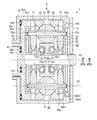
最初に、本実施例の無段変速機の一例について図1を用いて説明する。図1の符号1は、本実施例の無段変速機を示す。 First, an example of a continuously variable transmission according to the present embodiment will be described with reference to FIG. Reference numeral 1 in FIG. 1 indicates a continuously variable transmission according to this embodiment.
この無段変速機1の主要部を成す無段変速機構は、共通の第1回転中心軸R1を有する相互間での相対回転が可能な第1から第4の回転要素10,20,30,40と、その第1回転中心軸R1と後述する基準位置において平行な別の第2回転中心軸R2を各々有する複数の第5回転要素50と、第1から第4の回転要素10,20,30,40の回転中心に配置した変速機回転軸としてのシャフト60と、を備えた所謂トラクション遊星ギヤ機構と云われるものである。この無段変速機1は、第2回転中心軸R2を第1回転中心軸R1に対して傾斜させ、第5回転要素50を傾転させることによって、入出力間の変速比を変えるものである。以下においては、特に言及しない限り、その第1回転中心軸R1や第2回転中心軸R2に沿う方向を軸線方向と云い、その第1回転中心軸R1周りの方向を周方向と云う。また、その第1回転中心軸R1に直交する方向を径方向と云い、その中でも、内方に向けた側を径方向内側と、外方に向けた側を径方向外側と云う。この無段変速機1においては、第1から第4の回転要素10,20,30,40の内の何れか1つを周方向へと回転させぬよう固定し、その内の残りが周方向に回転できるようになっている。
The continuously variable transmission mechanism that forms the main part of the continuously variable transmission 1 includes first to fourth
この無段変速機1においては、第1回転要素10と第2回転要素20と第3回転要素30と第4回転要素40との間で各第5回転要素50を介したトルクの伝達が行われる。例えば、この無段変速機1においては、第1から第4の回転要素10,20,30,40の内の1つがトルク(動力)の入力部となり、残りの回転要素の内の少なくとも1つがトルクの出力部となる。これが為、この無段変速機1においては、入力部となる何れかの回転要素と出力部となる何れかの回転要素との間の回転速度(回転数)の比が変速比となる。例えば、この無段変速機1は、車両の動力伝達経路上に配設される。その際には、その入力部がエンジンやモータ等の動力源側に連結され、その出力部が駆動輪側に連結される。この無段変速機1においては、入力部としての回転要素にトルクが入力された場合の各回転要素の回転動作を正駆動と云い、出力部としての回転要素に正駆動時とは逆方向のトルクが入力された場合の各回転要素の回転動作を逆駆動と云う。例えば、この無段変速機1は、先の車両の例示に従えば、加速等の様に動力源側からトルクが入力部たる回転要素に入力されて当該回転要素を回転させているときが正駆動となり、減速等の様に駆動輪側から出力部たる回転中の回転要素に正駆動時とは逆方向のトルクが入力されているときが逆駆動となる。
In the continuously variable transmission 1, torque is transmitted between the first
この無段変速機1においては、シャフト60の中心軸(第1回転中心軸R1)を中心にして放射状に複数個の第5回転要素50を配置する。その夫々の第5回転要素50は、対向させて配置した第1回転要素10と第2回転要素20とで挟持させると共に、第3回転要素30の外周面上に配設する。また、夫々の第5回転要素50は、自身の回転中心軸(第2回転中心軸R2)を中心にした自転を行う。更に、第5回転要素50は、第4回転要素40が上記の固定対象になっていなければ、その第4回転要素40と一緒に回転して、第1回転中心軸R1を中心にした公転を行う。この無段変速機1は、第1及び第2の回転要素10,20の内の少なくとも一方を第5回転要素50に押し付けることによって、第1から第4の回転要素10,20,30,40と第5回転要素50との間に適切な摩擦力(トラクション力)を発生させ、その間におけるトルクの伝達を可能にする。また、この無段変速機1は、夫々の第5回転要素50を自身の第2回転中心軸R2と第1回転中心軸R1とを含む平面上で傾転させ、第1回転要素10と第2回転要素20との間の回転速度(回転数)の比を変化させることによって、入出力間の回転速度(回転数)の比を変える。
In the continuously variable transmission 1, a plurality of
ここで、この無段変速機1においては、第1及び第2の回転要素10,20が遊星歯車機構で云うところのリングギヤの機能を為すものとなる。また、第3回転要素30はトラクション遊星ギヤ機構のサンローラとして機能し、第4回転要素40はキャリアとして機能する。また、第5回転要素50は、トラクション遊星ギヤ機構におけるボール型ピニオンとして機能する。以下、第1及び第2の回転要素10,20については、各々「第1及び第2の回転部材10,20」と云う。また、第3回転要素30については「サンローラ30」と云い、第4回転要素40については「キャリア40」と云う。また、第5回転要素50については、「遊星ボール50」と云う。以下においては、キャリア40が上記の固定対象になっている場合を例に挙げて詳述する。
Here, in the continuously variable transmission 1, the first and second
第1及び第2の回転部材10,20は、第1回転中心軸R1を回転軸とする円盤部材(ディスク)や円環部材(リング)であり、軸線方向で対向させて各遊星ボール50を挟み込むように配設する。この例示においては、双方とも円環部材とする。尚、この第1及び第2の回転部材10,20を円盤部材とする場合には、シャフト60を挿入する為の円形の貫通孔が中心に形成されている。具体的に、第1及び第2の回転部材10,20は、後述するスラスト軸受TB2,TB1を介してシャフト60に対する周方向の相対回転を行うことができる。また、この第1及び第2の回転部材10,20は、後で詳述する各遊星ボール50の径方向外側の外周曲面と接触する接触面を有している。その夫々の接触面は、例えば、遊星ボール50の外周曲面の曲率と同等の曲率の凹円弧面、その外周曲面の曲率とは異なる曲率の凹円弧面、凸円弧面又は平面等の形状を成している。ここでは、後述する基準位置の状態で第1回転中心軸R1から各遊星ボール50との接触部分までの距離が同じ長さになるように夫々の接触面を形成して、第1及び第2の回転部材10,20の各遊星ボール50に対する夫々の接触角が同じ角度になるようにしている。その接触角とは、基準から各遊星ボール50との接触部分までの角度のことである。ここでは、径方向を基準にしている。その夫々の接触面は、遊星ボール50の外周曲面に対して点接触又は面接触している。また、夫々の接触面は、第1及び第2の回転部材10,20から遊星ボール50に向けて軸線方向の力が加わった際に、その遊星ボール50に対して径方向内側で且つ斜め方向の力が加わるように形成されている。
The first and second
サンローラ30は、第1回転中心軸R1を回転軸とした円筒状に成型する。このサンローラ30の外周面には、複数個の遊星ボール50が放射状に略等間隔で配置される。従って、このサンローラ30においては、その外周面が遊星ボール50の自転の際の転動面となる。このサンローラ30は、自らの回転動作によって夫々の遊星ボール50を転動(自転)させることもできれば、夫々の遊星ボール50の転動動作(自転動作)に伴って回転することもできる。また、このサンローラ30には、その内周面の軸線方向における中間部分に環状部30aを設ける。環状部30aは、その両側面が第1回転中心軸R1と直交する環状面になっている。
The
ここで、サンローラ30は、その環状部30aの内方に挿入されたシャフト60に対して周方向に相対回転できるように支持する。その支持は、サンローラ30とシャフト60の間に配設した軸受を介して行う。その軸受は、所謂アンギュラ軸受に相当するものであり、内輪(インナーレース)に相当する軸受部材31,32と、外輪(アウターレース)に相当する軸受部材33,34と、軸受ボール35と、を備える。例えば、軸受部材31,32は、内方にシャフト60を挿入できるよう円筒状に成型し、そのシャフト60上で対向させ且つシャフト60に対する軸線方向への相対移動ができないように配設する。この軸受部材31,32には、軸受ボール35の転動を支える環状の転動面31a,32aが形成される。その転動面31a,32aは、径方向内側に形成された環状の凹曲面と、径方向外側に形成された環状の側壁面と、を有する。その側壁面は、環状部30aの環状面に対して軸線方向で対向させる。一方、軸受部材33,34は、サンローラ30の内周面から環状部30aの環状面に沿わせた形状のものであり、サンローラ30に嵌合等で一体化されている。この軸受部材33,34は、軸受ボール35の転動を支える環状の転動面33a,34aを有する。その転動面33a,34aは、環状部30aの環状面に沿う環状部分に形成されたものであり、環状部30aの環状面と平行にしている。また、軸受ボール35は、その軸受部材31,33の間と軸受部材32,34の間に第1回転中心軸R1を中心にして放射状に複数個配設する。この軸受ボール35は、軸線方向へと力が加えられた際に、その力を転動面31a,32aにおける側壁面へと伝達できるように配置されることが望ましい。
Here, the
キャリア40は、例えば、第1回転中心軸R1を回転軸とする第1及び第2の円盤部41,42を対向させて配置し、その第1及び第2の円盤部41,42を複数本の連結軸(図示略)で連結して、全体として籠状となるようにする。これにより、このキャリア40は、外周面に開放部分を有することになる。各遊星ボール50は、第1及び第2の円盤部41,42の間に配置し、その開放部分を介してキャリア40の外周面から径方向外側に一部分を突出させている。ここで例示するキャリア40は、前述したように固定対象になっており、周方向への回転を行わせない。
The
遊星ボール50は、サンローラ30の外周面上を転がる転動部材である。この遊星ボール50は、完全な球状体であることが好ましいが、少なくとも転動方向にて球形を成すもの、例えばラグビーボールの様な断面が楕円形状のものであってもよい。この遊星ボール50は、その中心を通って貫通させた支持軸51によって回転自在に支持する。例えば、遊星ボール50は、支持軸51の外周面との間に配設した軸受(図示略)によって、第2回転中心軸R2を回転軸とした支持軸51に対する相対回転(つまり自転)ができるようにしている。従って、この遊星ボール50は、支持軸51を中心にしてサンローラ30の外周面上を転動することができる。
The
その支持軸51の基準となる位置は、図1に示すように、第2回転中心軸R2が第1回転中心軸R1と平行になる位置である。この支持軸51は、その基準位置で形成される自身の回転中心軸(第2回転中心軸R2)と第1回転中心軸R1とを含む平面内において、基準位置とそこから傾斜させた位置との間を遊星ボール50と共に揺動(傾転)することができる。その傾転は、その平面内で遊星ボール50の中心を支点にして行われる。
The reference position of the
この無段変速機1には、夫々の遊星ボール50を傾転させることによって変速させる変速制御部が設けられている。その遊星ボール50の傾転機構を成す変速制御部としては、この技術分野において周知のものを利用すればよい。例えば、この変速制御部としては、遊星ボール50から突出させた支持軸51の夫々の突出端部の内の少なくとも一方を上述した平面内で動作させるものが考えられる。この変速制御部は、その夫々の突出端部と、一方の突出端部が収められる第1円盤部材52の溝52aと、他方の突出端部が収められる第2円盤部材53の溝53aと、第1円盤部材52又は第2円盤部材53の内の少なくとも一方を他方に対して周方向に相対回転させる駆動装置(図示略)と、を備える。ここでは、駆動装置で第2円盤部材53を回転させる。その夫々の溝52a,53aは、突出端部よりも広い幅と遊星ボール50の傾転角に応じた長さとを有しており、第2円盤部材53の回転に伴い突出端部を上記の平面内で長手方向に案内する形状(例えば弧状や矩形状)になっている。このような形状の夫々の溝52a,53aは、突出端部を上記の平面内に沿って移動させる為に、第1回転中心軸R1を中心とした放射方向に対して傾斜させる。また、駆動装置は、例えば第1円盤部材52又は第2円盤部材53の内の少なくとも一方の外周面のネジ部に螺合させたウォームギヤであり、電動モータを電子制御装置(ECU)に制御させることで動作させる。この例示では、後述するように第2円盤部材53の外周面にラジアル軸受RBを設けているので、第1円盤部材52の外周面にウォームギヤを配設する。この変速制御部においては、第2円盤部材53の回転に伴い一方の突出端部が図1の紙面下方に動いたならば、他方の突出端部が図1の紙面上方に動く。また、第2円盤部材53を逆回転させたときには、夫々の突出端部が逆方向に上下動する。これにより、この無段変速機1においては、支持軸51に上記の平面に沿った傾転力が付与されるので、その支持軸51と共に遊星ボール50を傾転させることができる。
The continuously variable transmission 1 is provided with a shift control unit that shifts each
この無段変速機1においては、夫々の遊星ボール50の傾転角が0度のときに、第1回転部材10と第2回転部材20とが同一回転速度(同一回転数)で回転する。つまり、このときには、第1回転部材10と第2回転部材20の回転比(回転速度又は回転数の比)が1になっている。一方、夫々の遊星ボール50を基準位置から傾転させた際には、第1回転部材10との接触部分(接触点)及び第2回転部材20との接触部分(接触点)が変わり、支持軸51の中心軸から第1回転部材10との接触部分までの距離が変化すると共に、支持軸51の中心軸から第2回転部材20との接触部分までの距離が変化する。これが為、第1回転部材10又は第2回転部材20の内の何れか一方が基準位置のときよりも高速で回転し、他方が低速で回転するようになる。例えば第2回転部材20は、遊星ボール50を一方へと傾転させたときに第1回転部材10よりも低回転になり(減速)、他方へと傾転させたときに第1回転部材10よりも高回転になる(増速)。従って、この無段変速機1においては、その傾転角を変えることによって、第1回転部材10と第2回転部材20との間の回転比を無段階に変化させることができる。尚、ここでの増速時には、図1における上側の遊星ボール50を紙面時計回り方向に傾転させ且つ下側の遊星ボール50を紙面反時計回り方向に傾転させる。また、減速時には、図1における上側の遊星ボール50を紙面反時計回り方向に傾転させ且つ下側の遊星ボール50を紙面時計回り方向に傾転させる。
In the continuously variable transmission 1, when the tilt angle of each
この無段変速機1には、第1又は第2の回転部材10,20の内の少なくとも何れか一方を各遊星ボール50に押し付けて、第1及び第2の回転部材10,20と各遊星ボール50との間に挟圧力を発生させる押圧部が設けられている。その押圧部は、軸線方向の力(押圧力)を発生させることで、その間に挟圧力を生じさせるものである。その間においては、その挟圧力によって適切な摩擦力(トラクション力)が発生し、入力側となる何れか一方の回転トルクを効率良く他方に伝える。また、その押圧部の押圧力は、第1及び第2の回転部材10,20の接触面と各遊星ボール50の外周曲面の形状及び位置関係によって、各遊星ボール50を介してサンローラ30にも伝わる。これが為、サンローラ30と各遊星ボール50との間にも適切な摩擦力(トラクション力)が発生して、入力側となる何れか一方の回転トルクを効率良く他方に伝える。従って、その押圧力は、各遊星ボール50を介した第1回転部材10と第2回転部材20とサンローラ30との間のトルク伝達を維持し得る大きさとする。
In this continuously variable transmission 1, at least one of the first or second
この押圧部は、第1回転部材10側と第2回転部材20側の双方又は一方に設ける。この例示においては、押圧部としてのトルクカム機構を双方に設けることにする。第1回転部材10側には、第1回転部材10を遊星ボール50に押し付けることが可能なトルクカム71を配設し、第2回転部材20側には、第2回転部材20を遊星ボール50に押し付けることが可能なトルクカム72を配設する。
This pressing portion is provided on both or one of the first rotating
トルクカム71は、第1回転部材10と第1トルク伝達部材81との間でのトルク伝達を可能にするものでもあり、これらの間に配設する。ここで、第1トルク伝達部材81は、第1回転中心軸R1を中心にしたシャフト60に対する周方向への回転が可能な回転部材であって、シャフト60が挿入される貫通孔を有する円盤部81aと、第1回転部材10におけるトルクカム71側の環状面に対向させるべく突設した環状部81bと、を有する。その円盤部81aと後述するシャフト60の環状部60aとの間にはスラスト軸受TB1が配設されており、第1トルク伝達部材81は、シャフト60や第1回転部材10等に対する相対回転が可能になっている。トルクカム71は、図2に示すように、第1トルク伝達部材81と一体になって回転する第1係合部材71aと、第1回転部材10と一体になって回転する第2係合部材71bと、その第1係合部材71aと第2係合部材71bに挟持されるカムローラ71cと、を有している。その第1係合部材71aと第2係合部材71bは、第1回転中心軸R1を回転軸とする環状部材である。一方、カムローラ71cは、第1係合部材71aと第2係合部材71bの互いに対向する面に各々形成したカム面71dにおいて挟持する。
The
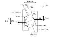
このトルクカム71は、第1係合部材71a又は第2係合部材71bの回転トルクを軸力Faに変換し、その軸力Faを押圧力として第1回転部材10に伝えるものである。このトルクカム71においては、第1係合部材71aに正転方向のトルクが入力されているとき又は第2係合部材71bに逆転方向のトルクが入力されているときに、夫々のカム面71dの間隔が狭くなり、その夫々のカム面71dがカムローラ71cを挟み付けて相互に一体化されて、軸力Faを発生させる。これが為、夫々の対向するカム面71dは、一方が基準面に対する軸線方向の間隔を正転時の周方向に向けて徐々に拡げるよう傾斜させ、他方が基準面に対する軸線方向の間隔を正転時の周方向に向けて徐々に狭めるよう傾斜させる。その基準面とは、第1回転中心軸R1に対する垂線を含む仮想平面である。更に、このトルクカム71においては、その夫々のカム面71dに連なる爪71eが第1係合部材71aと第2係合部材71bとに形成されており、第1係合部材71aに逆転方向のトルクが入力されているとき又は第2係合部材71bに正転方向のトルクが入力されているときに、夫々の爪71eがカムローラ71cに引っかかり、軸力Faを発生させはしないが、第1係合部材71aと第2係合部材71bとが一体になって回転する。このトルクカム71においては、カムローラ71cが複数個用意されており、その数に合わせてカム面71dや爪71eも形成する。ここでは、便宜上、一方の周方向の回転を「正転」と云い、これとは逆方向の回転を「逆転」と云う。尚、トルクカム71は、何れの回転要素を入力部にした場合でも、正駆動時と逆駆動時に軸力Faを発生させるように設定することが好ましい。尚、図2の「Ftcam」は、カムローラ71cを挟み付けている箇所における円周方向(接線方向)の荷重を示している。また、「α1,α2」は、カム面71dの傾斜角度(つまりカム角)を示している。
The
一方、トルクカム72は、第2回転部材20と第2トルク伝達部材82との間でのトルク伝達を可能にするものでもあり、これらの間に配設する。ここで、第2トルク伝達部材82は、第1回転中心軸R1を中心にしたシャフト60に対する周方向への回転が可能な回転部材であって、第1及び第2の回転部材10,20の外周面を覆う円筒部82aと、この円筒部82aの第2回転部材20側の内周面から径方向内側に延設した環状部82bと、円筒部82aの第1回転部材10側の内周面から径方向内側に延設した円盤部82cと、を有する。その環状部82bは、第2回転部材20におけるトルクカム72側の環状面20aと軸線方向で対向する第1環状面82b1と、この第1環状面82b1に対して軸線方向で反対側に位置する第2環状面82b2と、ラジアル軸受RBの外輪(アウターレース)が嵌合される環状の軸受保持部82b3と、を有している。ここでは、そのラジアル軸受RBの内輪(インナーレース)を第2円盤部材53の外周面に嵌合させる。一方、円盤部82cは、第1トルク伝達部材81の円盤部81aの円盤面を外から覆うものである、この円盤部82cと円盤部81aとの間には、スラスト軸受TB2が配設されている。第2トルク伝達部材82は、そのラジアル軸受RBやスラスト軸受TB2によって、シャフト60、第1回転部材10や第2回転部材20等に対する相対回転が可能になっている。
On the other hand, the
トルクカム72は、図2に示すように、トルクカム71と同様の第1係合部材72a、第2係合部材72b及びカムローラ72cを有しており、夫々のカム面72dでカムローラ72cを挟持する。その第1係合部材72aは、第2回転部材20と一体になって回転し、第2係合部材72bは、第2トルク伝達部材82と一体になって回転する。このトルクカム72は、トルクカム71と同様に、第1係合部材72aに正転方向のトルクが入力されているとき又は第2係合部材72bに逆転方向のトルクが入力されているときに軸力Faを発生させる。このトルクカム72は、その軸力Faを押圧力として第2回転部材20に伝える。また、このトルクカム72は、第1係合部材72aに逆転方向のトルクが入力されているとき又は第2係合部材72bに正転方向のトルクが入力されているときに、夫々の爪72eがカムローラ72cに引っかかり、軸力Faを発生させはしないが、第1係合部材72aと第2係合部材72bとが一体になって回転する。このトルクカム72においても、カムローラ72cが複数個用意されており、その数に合わせてカム面72dや爪72eも形成されている。尚、このトルクカム72は、何れの回転要素を入力部にした場合でも、正駆動時と逆駆動時に軸力Faを発生させるように設定することが好ましい。
As shown in FIG. 2, the
ここで、第1トルク伝達部材81は、後述する第2副押圧部による押圧力を第1回転部材10側に伝える押圧力伝達部材として機能すると共に、例えば動力源側に連結されることで無段変速機1の入力部として機能する。一方、第2トルク伝達部材82は、後述する第1副押圧部による押圧力を第2回転部材20側に伝える押圧力伝達部材として機能すると共に、例えば駆動輪側に連結されることで無段変速機1の出力部として機能する。
Here, the first
この無段変速機1においては、第1回転部材10の回転に伴い第1回転部材10と夫々の遊星ボール50との間に摩擦力(トラクション力Ft)が発生し、夫々の遊星ボール50が自転を始める。そして、この無段変速機1においては、その夫々の遊星ボール50の回転によって、各遊星ボール50と第2回転部材20との間、各遊星ボール50とサンローラ30との間にも摩擦力が発生し、その第2回転部材20とサンローラ30も回転を始める。
In the continuously variable transmission 1, a frictional force (traction force Ft) is generated between the first rotating
また、この無段変速機1においては、第2回転部材20の回転に伴い第2回転部材20と夫々の遊星ボール50との間に摩擦力が発生し、夫々の遊星ボール50が自転を始める。そして、この無段変速機1においては、その夫々の遊星ボール50の回転によって、各遊星ボール50と第1回転部材10との間、各遊星ボール50とサンローラ30との間にも摩擦力が発生し、その第1回転部材10とサンローラ30も回転を始める。
In the continuously variable transmission 1, a frictional force is generated between the second rotating
また、この無段変速機1においては、サンローラ30の回転に伴いサンローラ30と夫々の遊星ボール50との間に摩擦力が発生し、夫々の遊星ボール50が自転を始める。そして、この無段変速機1においては、その夫々の遊星ボール50の回転によって、各遊星ボール50と第1回転部材10との間、各遊星ボール50と第2回転部材20との間にも摩擦力が発生し、その第1回転部材10と第2回転部材20も回転を始める。
In the continuously variable transmission 1, a frictional force is generated between the
尚、この無段変速機1においては、キャリア40以外の回転要素を固定対象に設定した場合、そのキャリア40の回転に伴い夫々の遊星ボール50が自転と公転を始める。そして、この無段変速機1においては、その夫々の遊星ボール50の回転によって、各遊星ボール50と第1回転部材10との間、各遊星ボール50と第2回転部材20との間、各遊星ボール50とサンローラ30との間にも摩擦力が発生し、その第1回転部材10と第2回転部材20とサンローラ30も回転を始める。
In the continuously variable transmission 1, when a rotating element other than the
この無段変速機1においては、正駆動時又は逆駆動時に、トルクカム71,72で軸力Faが発生し、その軸力Faが押圧力として第1回転部材10と第2回転部材20に伝達される。そして、その押圧力は、第1回転部材10、第2回転部材20及びサンローラ30と夫々の遊星ボール50との間の摩擦力を増加させる。これにより、この無段変速機1においては、その間における正駆動時又は逆駆動時のトルクの伝達効率が上昇する。例えば、動力源側に第1トルク伝達部材81を入力部として連結し、駆動輪側に第2トルク伝達部材82を出力部として連結した場合、この無段変速機1は、正駆動時に動力源の動力を変速比に応じて変速し、その変速後の動力を駆動輪側に車両の駆動力として伝えることができる。一方、逆駆動時には、動力源がエンジンならばエンジンブレーキを発生させることができ、また、動力源がモータならば電力の回生や回生制動を行うことができる。
In the continuously variable transmission 1, an axial force Fa is generated by the
このように、この無段変速機1においては、トルクカム71,72によってトルクの伝達効率を上昇させている。しかしながら、この種の無段変速機1は、入力トルクが高いほど大きな押圧力で遊星ボール50を押し付けなければ、その入力トルクに応じた摩擦力を発生させることができず、トルクの伝達効率が低下してしまう虞がある。例えば、動力源の出力トルクが高いときには、無段変速機1への入力トルクも高くなるので、押圧力が不足していると、トルクの伝達効率が低下してしまう可能性がある。これが為、この無段変速機1は、高い入力トルクに対応させるべく、そのトルクカム71,72の軸力Faによる押圧力に加えて、別の押圧力で第1回転部材10又は第2回転部材20の内の少なくとも一方を遊星ボール50に押し付けるようにする。以下、主な押圧力(軸力Fa)を発生させる押圧部(ここではトルクカム71,72)のことを「主押圧部」と云い、この主押圧部とは別の押圧力を発生させる押圧部のことを「副押圧部」と云う。
Thus, in this continuously variable transmission 1, the torque transmission efficiency is increased by the
副押圧部は、正駆動時に押圧力を発生させるものと、逆駆動時に押圧力を発生させるものとを個別に用意する。以下、正駆動時に押圧力を発生させる副押圧部のことを第1副押圧部(第1押圧部)と云い、逆駆動時に押圧力を発生させる副押圧部のことを第2副押圧部(第2押圧部)と云う。 The sub-pressing unit is prepared separately for generating a pressing force during forward driving and for generating a pressing force during reverse driving. Hereinafter, a sub-pressing portion that generates a pressing force during forward driving is referred to as a first sub-pressing portion (first pressing portion), and a sub-pressing portion that generates a pressing force during reverse driving is referred to as a second sub-pressing portion ( This is called a second pressing portion.
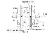
ところで、遊星ボール50における第1回転部材10との接触部分においては、第1回転部材10が回転し始めたときに、その回転方向と同じ向きの接線方向の摩擦力が加わる。そして、その接触部分は、遊星ボール50の外周面上において遊星ボール50の重心からずらした位置にある。これが為、その摩擦力は遊星ボール50において偏心荷重となるので、その摩擦力が加わった際には、その重心を中心にした回転モーメント(以下、「偏心荷重モーメント」という。)が遊星ボール50に発生する。更に、この無段変速機1の動作中においては、図3又は図4に示すように、遊星ボール50における第1回転部材10との接触部分と第2回転部材20との接触部分とに逆方向の摩擦力が定常的に発生している。例えば、第1回転部材10を入力側、第2回転部材20を出力側とした正転時の場合、第1回転部材10との接触部分においては、第1回転部材10の回転方向と同じ向きの接線方向の摩擦力となり、第2回転部材20との接触部分においては、第2回転部材20の回転方向とは逆向きの接線方向の摩擦力となる。これが為、遊星ボール50には、その摩擦力の向きの違いによって、重心を中心にした偏心荷重モーメントが発生する。
By the way, in the contact part with the
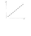
ここで、無段変速機1においては、遊星ボール50の傾転動作を円滑にする為に、その傾転動作の際に動作させる部材間に隙間を設けている。例えば、この例示においては、上述した支持軸51の夫々の突出端部と第1及び第2の円盤部材52,53の夫々の溝52a,53aとの間に隙間を設けている。これが為、遊星ボール50は、上記の偏心荷重モーメントが発生した場合に、その隙間に応じた量だけ偏心荷重モーメントの方向へと傾いてしまう。つまり、偏心荷重モーメントの方向は上述した第1回転中心軸R1と第2回転中心軸R2とを含む平面に沿うものではないので、その際には、その隙間と偏心荷重モーメントによって、第1回転中心軸R1と第2回転中心軸R2との間の平行状態が崩れてしまい、第2回転中心軸R2が上述した平面内から外れてしまう。従って、サンローラ30と遊星ボール50との間には、スキューが発生する。故に、サンローラ30には、遊星ボール50の偏心荷重モーメントに応じた、換言するならば図3又は図4に示すサンローラ30の速度ベクトルと遊星ボール50の速度ベクトルのずれに応じた軸線方向のスラスト力が遊星ボール50から加わる。その図3に示すスラスト力は、正駆動時のものである。また、図4に示すスラスト力は、逆駆動時のものである。図5に示すように、スラスト力Fbは、トルクカム71,72の軸力Faとの間に線形性を持っている。第1及び第2の副押圧部は、そのスラスト力を利用する。
Here, in the continuously variable transmission 1, in order to make the
先ず、正駆動時の第1副押圧部について説明する。正駆動時のスラスト力は、図6に示すように、サンローラ30の環状部30aの環状面から軸受部材33に伝わり、その軸受部材33における環状の転動面33aを介して夫々の軸受ボール35に伝達された後、更に各軸受ボール35から軸受部材31の転動面31aにおける側壁面に伝達される。そして、このスラスト力は、軸受部材31からシャフト60に伝わる。従って、この第1副押圧部は、そのシャフト60に加わったスラスト力を第2回転部材20に押圧力として伝えるものにする。具体的に、この第1副押圧部は、第2回転部材20と遊星ボール50との接触部分に効率良く押圧力を加えるものであり、第1回転中心軸R1からその接触部分までの距離(接触半径)と同等の距離だけ第1回転中心軸R1から径方向外側に離れた軸線方向における或る位置(以下、「押圧位置」という。)に押圧面を備える。この第1副押圧部は、シャフト60に加わったスラスト力をその押圧面に伝え、その押圧面から第2回転部材20に向けて押圧力を加える。従って、この第1副押圧部は、その押圧面の他に、シャフト60に加わったスラスト力を押圧面に伝えるスラスト力伝達部材を有している。ここで、その押圧面は、例えば中心に第1回転中心軸R1を有し且つ接触半径と同等又はそれに近い内径と外径を有する環状面が考えられる。
First, the 1st sub press part at the time of a positive drive is demonstrated. As shown in FIG. 6, the thrust force during the positive drive is transmitted from the annular surface of the
ここで例示する第1副押圧部は、スラスト力伝達部材を成すと共に上記の押圧面を有する円盤部材91を備える。その円盤部材91は、第1回転中心軸R1を中心軸とする円盤状のものであり、シャフト60の外周面上に配設される。この円盤部材91は、そのシャフト60に対する相対的な動きの中でも少なくとも軸線方向への移動が禁止される。これが為、この円盤部材91には、シャフト60に加わったスラスト力がそのまま伝えられている。また、この円盤部材91は、その外径が少なくとも押圧面の外径と同等以上になるよう成型する。つまり、この円盤部材91の半径は、接触半径と同等又はそれに近い大きさになっている。これが為、この円盤部材91においては、その環状の平面の一部が押圧面となる。
The 1st subpressing part illustrated here is provided with the
この無段変速機1においては、その円盤部材91の押圧面をラジアル軸受RBの側面に当接させており、円盤部材91におけるスラスト力がその押圧面を介し押圧力としてラジアル軸受RBに伝えられる。そして、そのラジアル軸受RBに伝えられた押圧力は、反対側の側面を介して環状部82bの軸受保持部82b3における環状面に伝達される。ここでは、そのラジアル軸受RBの反対側の側面も押圧面となる。ここで、円盤部材91の押圧面と環状部82bの第2環状面82b2との間に例えばスラスト軸受(図示略)を介装させてもよく、この場合には、円盤部材91におけるスラスト力がその押圧面から押圧力としてスラスト軸受に伝えられ、その押圧力がスラスト軸受から第2環状面82b2を介して環状部82bに伝達される。
In this continuously variable transmission 1, the pressing surface of the
第2トルク伝達部材82の環状部82bに伝達された押圧力は、第1環状面82b1からトルクカム72へと伝わり、そのトルクカム72を介して第2回転部材20に加えられる。その押圧力は、第2回転部材20を介して夫々の遊星ボール50に働く。ここでは、その第1環状面82b1やトルクカム72における第2係合部材72bのカム面72d及び第1係合部材72aの第2回転部材20との当接面についても押圧面となる。
The pressing force transmitted to the
この無段変速機1における第1副押圧部は、軸線方向への相対移動が規制されたサンローラ30、軸受部材33、軸受ボール35、軸受部材31、シャフト60、円盤部材91、ラジアル軸受RB、第2トルク伝達部材82及びトルクカム72によって副押圧部としての機能を為すものであり、これらによって遊星ボール50からのスラスト力を押圧力として第2回転部材20へと伝えるものとなる。
The first sub-pressing portion in the continuously variable transmission 1 includes a
このように、本実施例の無段変速機1は、正駆動時に主押圧部としてのトルクカム71,72による押圧力に加えて第1副押圧部によるスラスト力を利用した押圧力も働くので、その2種類の押圧力で第1回転部材10、第2回転部材20及びサンローラ30と夫々の遊星ボール50との間の摩擦力を増加させ、その間におけるトルクの伝達効率を上昇させることができる。これが為、上記の例示の如き車両においては、無段変速機1の正駆動時におけるトルクの伝達効率が更に向上することになるので、動力源を高トルク化しても適切に駆動力を発生させることができる。
As described above, the continuously variable transmission 1 of the present embodiment works in addition to the pressing force by the
次に、逆駆動時の第2副押圧部について説明する。逆駆動時のスラスト力は、図4に示すように、正駆動時のスラスト力とは逆向きになる。このスラスト力は、環状部30aの環状面から軸受部材34に伝わり、その軸受部材34における環状の転動面34aを介して夫々の軸受ボール35に伝達された後、更に各軸受ボール35から軸受部材32の転動面32aにおける側壁面に伝達される。この逆駆動時のスラスト力は、軸受部材32を介してシャフト60に伝わる。従って、この第2副押圧部は、そのシャフト60に加わったスラスト力を第1回転部材10に押圧力として伝えるものにする。具体的に、この第2副押圧部は、図1及び図7に示すように、第1トルク伝達部材81の円盤部81aに軸線方向にて対向させたシャフト60の環状部60aと、その円盤部81aと環状部60aとの間に配設した環状のスラスト軸受TB1と、を備える。その環状部60aは、円盤部81aを外側から覆う位置に配置して、その円盤部81aの径方向内側部分にスラスト力が伝わるよう(つまりシャフト60の近くでスラスト力を伝えるよう)外径を設定する。シャフト60に加わったスラスト力は、その環状部60aとスラスト軸受TB1を介して第1トルク伝達部材81に押圧力として伝わる。その押圧力は、トルクカム71を介して第1回転部材10に伝わり、夫々の遊星ボール50に働く。厳密に述べるのであれば、この第2副押圧部は、軸線方向への相対移動が規制されたサンローラ30、軸受部材34、軸受ボール35、軸受部材32、シャフト60(主軸部分及び環状部60a)、スラスト軸受TB1、第1トルク伝達部材81及びトルクカム71によって副押圧部としての機能を為すものであり、これらによって遊星ボール50からのスラスト力を押圧力として第1回転部材10へと伝えるものとなる。
Next, the 2nd sub press part at the time of reverse drive is demonstrated. As shown in FIG. 4, the thrust force during reverse driving is opposite to the thrust force during forward driving. This thrust force is transmitted from the annular surface of the
このように、本実施例の無段変速機1は、逆駆動時にも正駆動時と同様に、主押圧部としてのトルクカム71,72による押圧力に加えて第2副押圧部による正駆動時とは逆向きのスラスト力を利用した押圧力も働くので、その2種類の押圧力で第1回転部材10、第2回転部材20及びサンローラ30と夫々の遊星ボール50との間の摩擦力を増加させ、その間におけるトルクの伝達効率を上昇させることができる。これが為、上記の例示の如き車両においては、無段変速機1の逆駆動時におけるトルクの伝達効率が更に向上することになるので、動力源がエンジンならば適度な大きさのエンジンブレーキを発生させることができ、また、動力源がモータならば適量な電力の回生や適度な大きさの回生制動を行うことができるようになる。
As described above, the continuously variable transmission 1 according to the present embodiment is also in the case of the forward drive by the second sub-pressing portion in addition to the pressing force by the
ここで、第1副押圧部について、シャフト60に加わったスラスト力を第2副押圧部の様なシャフト60に近い位置で押圧力として伝える構造にしたと仮定した場合、例えば第2副押圧部が第1副押圧部として利用される場合には、大きいスラスト力が発生しているときほど第1トルク伝達部材81に撓みが生じる可能性がある。特に、正駆動時には、動力源から高いトルクが入力されるので、スラスト力が大きくなって撓み発生の可能性が逆駆動時よりも高くなる。そして、その撓み発生の際には、第1トルク伝達部材81の外周面側が遊星ボール50から離れる方向に動き、これに伴いトルクカム71や第1回転部材10も遊星ボール50から離れてしまうので、第1回転部材10から遊星ボール50への押圧力が低くなってトルクの伝達効率を低下させてしまう虞がある。つまり、この無段変速機1は、入力トルクが高いほど大きな押圧力が必要になるにも拘わらず、それに反して押圧力が低くなるので、摩擦力が不足してトルクの伝達効率を低下させてしまう虞がある。これが為、この仮定状態の場合には、肉厚を厚くしたり高剛性の材料で成型したりして第1トルク伝達部材81の高剛性化を図り、第1トルク伝達部材81の撓み発生を抑える必要があるが、かかる対応策で無段変速機1の重量の増加や体格の大型化を招くので好ましくない。
Here, when it is assumed that the thrust force applied to the
しかしながら、本実施例の第1副押圧部は、第2回転部材20と遊星ボール50との接触位置に対して第1回転中心軸R1を中心にした径方向外側の同等の位置又はそれに近い位置に押圧位置(押圧面)を設けているので、仮定において説明したような撓みの発生を抑えることができる。従って、本実施例の無段変速機1は、高いトルクが入力される正駆動時においても、発生したスラスト力を押圧力として効率良く利用することができるので、良好なトルク伝達効率での動作が可能になる。ここで、その撓み発生の抑制という観点に立つならば、第1副押圧部は、第2回転部材20と遊星ボール50との接触位置に対して径方向外側の同等の位置よりも外側に設けてもよく、このようにしても同様の作用効果を得ることができる。つまり、第1副押圧部は、第1回転中心軸R1から径方向外側に向けた距離が、第1回転中心軸R1から第2回転部材20と遊星ボール50との接触位置までの接触半径と同等以上の距離となる位置に押圧位置(押圧面)を設けることが好ましい。
However, the first sub-pressing portion of the present embodiment is an equivalent position on the outer side in the radial direction around the first rotation center axis R1 with respect to the contact position between the second rotating
一方、逆駆動時には、入力トルクが正駆動時ほど大きくないので、スラスト力が正駆動時よりも小さい。これが為、第2副押圧部は、シャフト60に近い位置で押圧力として伝える構造を採用しても第1トルク伝達部材81を撓ませることがない。従って、本実施例の無段変速機1は、逆駆動時においても、発生したスラスト力を押圧力として効率良く利用することができるので、良好なトルク伝達効率での動作が可能になる。
On the other hand, during reverse drive, the input torque is not as great as during forward drive, so the thrust force is smaller than during forward drive. For this reason, the second sub-pressing portion does not bend the first
以上示したように、本実施例の無段変速機1は、適度な大きさの押圧力を正駆動時、逆駆動時に拘わらず発生させることができる。また、この無段変速機1においては、その押圧力を発生させる為の機構や構造の大型化を抑えることができる。これが為、この無段変速機1は、車両等への搭載性にも優れたものとなる。 As described above, the continuously variable transmission 1 according to the present embodiment can generate a moderately large pressing force regardless of whether it is forward driven or reverse driven. Moreover, in this continuously variable transmission 1, the enlargement of the mechanism and structure for generating the pressing force can be suppressed. For this reason, the continuously variable transmission 1 is excellent in mountability to a vehicle or the like.
ここで、本実施例においては主押圧部としてトルクカム機構によるものを例示したが、その主押圧部は、液体や気体の圧力を利用して押圧力を発生させる液圧押圧機構や気圧押圧機構であってもよい。その液圧押圧機構や気圧押圧機構は、主押圧部としての押圧力が必要とされるとき(例えば正駆動時や逆駆動時)に、その動作が制御装置によって制御される。この場合の無段変速機においては、主押圧部による押圧力の大きさを制御することによって、過不足のない必要全押圧力を発生させることができる。また、この無段変速機においては、第1副押圧部や第2副押圧部による押圧力の分だけ主押圧部で発生させる押圧力を小さくできるので、低い液圧又は気圧で過不足のない必要全押圧力を発生させることができ、その液圧又は気圧を発生させる為のポンプ等における駆動損失の低減が可能になる。 Here, in the present embodiment, the main pressing portion is exemplified by a torque cam mechanism, but the main pressing portion is a hydraulic pressure mechanism or an atmospheric pressure mechanism that generates a pressing force using the pressure of liquid or gas. There may be. The hydraulic pressure pressing mechanism and the atmospheric pressure pressing mechanism are controlled by the control device when the pressing force as the main pressing portion is required (for example, at the time of forward driving or at the time of reverse driving). In the continuously variable transmission in this case, it is possible to generate the necessary total pressing force without excess or deficiency by controlling the magnitude of the pressing force by the main pressing portion. Further, in this continuously variable transmission, the pressing force generated in the main pressing portion can be reduced by the pressing force of the first sub-pressing portion and the second sub-pressing portion, so there is no excess or deficiency at low hydraulic pressure or atmospheric pressure. The necessary total pressing force can be generated, and the driving loss in a pump or the like for generating the hydraulic pressure or the atmospheric pressure can be reduced.
また、以上示した無段変速機1においてはシャフト60に対して相対回転可能なサンローラ30を備えているが、そのようなサンローラ30が無い無段変速機においても同様の作用効果を奏することができる。そのサンローラ30の無い無段変速機とは、例えば、無段変速機1において、シャフト60の外周面上に放射状に遊星ボール50を複数個配設したもの、軸線方向への相対移動ができぬようシャフト60に取り付けた円筒部材の外周面上に放射状に遊星ボール50を複数個配設したものなどである。前者の無段変速機においては、遊星ボール50からシャフト60に直接スラスト力が加わるので、そのスラスト力を利用した押圧力の発生が可能になる。また、後者の無段変速機においては、円筒部材を介してシャフト60に加わることになるので、そのスラスト力を利用した押圧力の発生が可能になる。
In addition, the continuously variable transmission 1 described above includes the
尚、ここで例示した無段変速機1においては主押圧部を設けているが、例えば小さい入力トルクしか入力されない場合には、第1副押圧部と第2副押圧部のみで押圧力を発生させるように無段変速機を構築してもよい。 In the continuously variable transmission 1 illustrated here, the main pressing portion is provided. However, when only a small input torque is input, for example, the pressing force is generated only by the first sub pressing portion and the second sub pressing portion. A continuously variable transmission may be constructed so that
以上のように、本発明に係る無段変速機は、押圧力として利用するスラスト力の伝達効率を向上させる為の技術に有用である。 As described above, the continuously variable transmission according to the present invention is useful for a technique for improving the transmission efficiency of a thrust force used as a pressing force.
1 無段変速機
10 第1回転部材(第1回転要素)
20 第2回転部材(第2回転要素)
30 サンローラ(第3回転要素)
30a 環状部
31,32,33,34 軸受部材
31a,32a,33a,34a 転動面
35 軸受ボール
40 キャリア(第4回転要素)
50 遊星ボール(転動部材、第5回転要素)
51 支持軸
52,53 円盤部材
52a,53a 溝
60 シャフト(変速機回転軸)
60a 環状部
71,72 トルクカム(主押圧部)
81 第1トルク伝達部材
81a 円盤部
81b 環状部
82 第2トルク伝達部材
82b 環状部
82b1 第1環状面
82b2 第2環状面
82b3 軸受保持部
91 円盤部材
R1 第1回転中心軸
R2 第2回転中心軸
RB ラジアル軸受
TB1,TB2 スラスト軸受
1 continuously
20 Second rotating member (second rotating element)
30 Sun Roller (third rotating element)
50 planetary ball (rolling member, fifth rotating element)
51
81 1st
Claims (6)
前記第1回転中心軸とは別の第2回転中心軸を有し、前記第1回転要素と前記第2回転要素とで挟持されて当該第1及び第2の回転要素との間におけるトルク伝達を可能にする転動部材と、
前記転動部材を傾転させることで前記第1及び第2の回転要素の間の回転比を変化させる変速制御部と、
前記転動部材から加えられたスラスト力を当該転動部材に対する押圧力として前記第1又は第2の回転要素の内の一方に伝える押圧部と、
を設け、
前記押圧部は、前記第1回転中心軸から径方向外側に向けた距離が、該第1回転中心軸から前記一方の回転要素と前記転動部材との接触位置までの接触半径と同等以上の距離となる位置に当該一方の回転要素に向けた押圧位置を備えることを特徴とした無段変速機。 First and second rotating elements having a common first rotation center axis facing each other and capable of relative rotation;
Torque transmission between the first and second rotating elements having a second rotating center axis different from the first rotating center axis and sandwiched between the first rotating element and the second rotating element Rolling members that enable
A transmission control unit that changes a rotation ratio between the first and second rotating elements by tilting the rolling member;
A pressing portion for transmitting a thrust force applied from the rolling member to one of the first or second rotating elements as a pressing force against the rolling member;
Provided,
The pressing portion has a distance from the first rotation center axis to the radially outer side equal to or greater than a contact radius from the first rotation center axis to a contact position between the one rotation element and the rolling member. A continuously variable transmission comprising a pressing position directed to the one rotating element at a position corresponding to a distance.
前記押圧部は、前記変速機回転軸に加えられた前記スラスト力を前記押圧位置まで伝えるスラスト力伝達部材を有することを特徴とした請求項1記載の無段変速機。 A transmission rotating shaft disposed at the center of rotation of the first and second rotating elements;
The continuously variable transmission according to claim 1, wherein the pressing portion includes a thrust force transmitting member that transmits the thrust force applied to the transmission rotation shaft to the pressing position.
前記第1回転中心軸とは別の第2回転中心軸を有し、前記第1回転要素と前記第2回転要素とで挟持されて当該第1及び第2の回転要素との間におけるトルク伝達を可能にする転動部材と、
前記転動部材を傾転させることで前記第1及び第2の回転要素の間の回転比を変化させる変速制御部と、
前記転動部材から加えられたスラスト力を当該転動部材に対する押圧力として前記第1又は第2の回転要素の内の一方に伝える第1押圧部と、
前記転動部材から加えられた前記スラスト力とは逆向きのスラスト力を当該転動部材に対する押圧力として前記第1又は第2の回転要素の内の他方に伝える第2押圧部と、
を設け、
前記第1押圧部は、前記第1回転中心軸から径方向外側に向けた距離が、該第1回転中心軸から前記一方の回転要素と前記転動部材との接触位置までの接触半径と同等以上の距離となる位置に当該一方の回転要素に向けた押圧位置を備えることを特徴とした無段変速機。 First and second rotating elements having a common first rotation center axis facing each other and capable of relative rotation;
Torque transmission between the first and second rotating elements having a second rotating center axis different from the first rotating center axis and sandwiched between the first rotating element and the second rotating element Rolling members that enable
A transmission control unit that changes a rotation ratio between the first and second rotating elements by tilting the rolling member;
A first pressing portion for transmitting a thrust force applied from the rolling member to one of the first or second rotating elements as a pressing force against the rolling member;
A second pressing portion that transmits a thrust force opposite to the thrust force applied from the rolling member to the other of the first or second rotating elements as a pressing force against the rolling member;
Provided,
The first pressing portion has a distance from the first rotation center axis radially outward to a contact radius from the first rotation center axis to a contact position between the one rotation element and the rolling member. A continuously variable transmission comprising a pressing position directed to the one rotating element at a position having the above distance.
前記第1回転中心軸を有し、前記第1から第3の回転要素に対する相対回転が可能で且つ前記第1回転中心軸を中心にして前記各転動部材を回転させることが可能な第4回転要素と、
を設け、
前記第1から第4の回転要素の内の何れか1つを前記第1回転中心軸を中心にして回転させぬようにすることを特徴とした請求項1から5の内の何れか1つに記載の無段変速機。 An outer peripheral surface having a first rotation center axis and a rolling surface of the rolling member arranged radially around the first rotation center axis, the first rotation axis relative to the first and second rotation elements; A third rotating element capable of relative rotation;
A fourth shaft having the first rotation center axis, capable of rotating relative to the first to third rotation elements, and capable of rotating the rolling members around the first rotation center axis. A rotating element;
Provided,
6. One of the first to fourth rotating elements according to claim 1, wherein any one of the first to fourth rotating elements is not rotated about the first rotation center axis. The continuously variable transmission described in 1.
Priority Applications (1)
| Application Number | Priority Date | Filing Date | Title |
|---|---|---|---|
| JP2010058136A JP2011190882A (en) | 2010-03-15 | 2010-03-15 | Continuously variable transmission |
Applications Claiming Priority (1)
| Application Number | Priority Date | Filing Date | Title |
|---|---|---|---|
| JP2010058136A JP2011190882A (en) | 2010-03-15 | 2010-03-15 | Continuously variable transmission |
Publications (1)
| Publication Number | Publication Date |
|---|---|
| JP2011190882A true JP2011190882A (en) | 2011-09-29 |
Family
ID=44796017
Family Applications (1)
| Application Number | Title | Priority Date | Filing Date |
|---|---|---|---|
| JP2010058136A Withdrawn JP2011190882A (en) | 2010-03-15 | 2010-03-15 | Continuously variable transmission |
Country Status (1)
| Country | Link |
|---|---|
| JP (1) | JP2011190882A (en) |
Cited By (3)
| Publication number | Priority date | Publication date | Assignee | Title |
|---|---|---|---|---|
| WO2013125041A1 (en) * | 2012-02-24 | 2013-08-29 | トヨタ自動車株式会社 | Continuously variable transmission |
| WO2014069141A1 (en) * | 2012-11-05 | 2014-05-08 | トヨタ自動車株式会社 | Stepless transmission |
| JPWO2013125041A1 (en) * | 2012-02-24 | 2015-07-30 | トヨタ自動車株式会社 | Continuously variable transmission |
-
2010
- 2010-03-15 JP JP2010058136A patent/JP2011190882A/en not_active Withdrawn
Cited By (8)
| Publication number | Priority date | Publication date | Assignee | Title |
|---|---|---|---|---|
| WO2013125041A1 (en) * | 2012-02-24 | 2013-08-29 | トヨタ自動車株式会社 | Continuously variable transmission |
| CN104136810A (en) * | 2012-02-24 | 2014-11-05 | 丰田自动车株式会社 | Continuously variable transmission |
| JPWO2013125041A1 (en) * | 2012-02-24 | 2015-07-30 | トヨタ自動車株式会社 | Continuously variable transmission |
| KR101541673B1 (en) | 2012-02-24 | 2015-08-03 | 도요타지도샤가부시키가이샤 | Continuously variable transmission |
| AU2012370697B2 (en) * | 2012-02-24 | 2015-09-03 | Toyota Jidosha Kabushiki Kaisha | Continuously variable transmission |
| CN104136810B (en) * | 2012-02-24 | 2016-10-19 | 丰田自动车株式会社 | CVT |
| WO2014069141A1 (en) * | 2012-11-05 | 2014-05-08 | トヨタ自動車株式会社 | Stepless transmission |
| JP2014092236A (en) * | 2012-11-05 | 2014-05-19 | Toyota Motor Corp | Continuously variable transmission |
Similar Documents
| Publication | Publication Date | Title |
|---|---|---|
| JP5131353B2 (en) | Continuously variable transmission | |
| US8382636B2 (en) | Continuously variable transmission | |
| JP5500118B2 (en) | Continuously variable transmission | |
| JP2012122568A (en) | Continuously variable transmission | |
| JP2012107725A (en) | Continuously variable transmission | |
| JP5903834B2 (en) | Friction roller speed reducer and electric vehicle drive device | |
| JP2014040885A (en) | Friction roller-type change gear | |
| JP2011190882A (en) | Continuously variable transmission | |
| JP5601420B2 (en) | Continuously variable transmission | |
| CN101283201B (en) | Planetary roller transmission device and vehicle equipped with the device | |
| JP2011153645A (en) | Continuously variable transmission and control device of continuously variable transmission | |
| WO2018070372A1 (en) | Continuously variable transmission and bicycle | |
| CN111279099B (en) | Continuously variable transmission and bicycle | |
| JP6119372B2 (en) | Loading cam device and friction roller reducer | |
| JP7422939B2 (en) | transmission | |
| JP2011190881A (en) | Continuously variable transmission | |
| JP2012127457A (en) | Continuously variable transmission | |
| JP2014214838A (en) | Continuously variable transmission | |
| JP5761445B2 (en) | Continuously variable transmission | |
| JP2012122567A (en) | Continuously variable transmission | |
| JP5488492B2 (en) | Continuously variable transmission | |
| JP2011202701A (en) | Continuously variable transmission | |
| JP2014040886A (en) | Friction roller type transmission | |
| JP2011202699A (en) | Continuously variable transmission | |
| JP2013190019A (en) | Continuously variable transmission |
Legal Events
| Date | Code | Title | Description |
|---|---|---|---|
| A300 | Withdrawal of application because of no request for examination |
Free format text: JAPANESE INTERMEDIATE CODE: A300 Effective date: 20130604 |