JP2011190872A - Control device of continuously variable transmission - Google Patents
Control device of continuously variable transmission Download PDFInfo
- Publication number
- JP2011190872A JP2011190872A JP2010057763A JP2010057763A JP2011190872A JP 2011190872 A JP2011190872 A JP 2011190872A JP 2010057763 A JP2010057763 A JP 2010057763A JP 2010057763 A JP2010057763 A JP 2010057763A JP 2011190872 A JP2011190872 A JP 2011190872A
- Authority
- JP
- Japan
- Prior art keywords
- target
- rotational speed
- driving force
- continuously variable
- variable transmission
- Prior art date
- Legal status (The legal status is an assumption and is not a legal conclusion. Google has not performed a legal analysis and makes no representation as to the accuracy of the status listed.)
- Withdrawn
Links
Images


Landscapes
- Control Of Transmission Device (AREA)
Abstract
Description
本発明は、無段変速機の制御装置に関し、特に、アクセル開度または目標駆動力に応じて目標回転数を設定し、入力軸の回転数が目標回転数になるように無段変速機を制御する技術に関する。 The present invention relates to a control device for a continuously variable transmission, and more particularly to a continuously variable transmission that sets a target rotational speed in accordance with an accelerator opening or a target driving force so that the rotational speed of an input shaft becomes a target rotational speed. It relates to the technology to control.
無段変速機を搭載した車両が知られている。無段変速機は、ギヤ比を無段階に変化させることが可能である。したがって、車速、すなわち無段変速機の出力軸回転数に対して、無段変速機の入力軸回転数、すなわち無段変速機に連結された駆動源(たとえばエンジンまたは電動モータ)の出力軸回転数を任意に変化させることが可能である。よって、燃費が最適(最小)となるように駆動源の出力軸回転数を調整することができる。 A vehicle equipped with a continuously variable transmission is known. The continuously variable transmission can change the gear ratio steplessly. Therefore, the input shaft rotation speed of the continuously variable transmission, that is, the output shaft rotation of a drive source (for example, an engine or an electric motor) connected to the continuously variable transmission, with respect to the vehicle speed, that is, the output shaft rotation speed of the continuously variable transmission. The number can be arbitrarily changed. Therefore, it is possible to adjust the output shaft rotational speed of the drive source so that the fuel consumption is optimum (minimum).
燃費が最適になるようにエンジン回転数を制御した場合、車速とエンジン回転数とが比例しない場合がある。たとえば、加速時においては、始めに、効率のよい回転数までエンジン回転数を上昇させるべく無段変速機がダウンシフトされ、その後、エンジン回転数を略一定に維持したまま、無段変速機がアップシフトしながら車両が加速する。このような現象は、ラバーバンドフィールと呼ばれる。一般的に、ドライバは、車速とともにエンジン回転数が増大することを期待する。したがって、無段変速機は燃費を向上する一方で、ラバーバンドフィールというドライバの期待に反する現象を伴なう。 When the engine speed is controlled to optimize fuel consumption, the vehicle speed may not be proportional to the engine speed. For example, at the time of acceleration, the continuously variable transmission is first downshifted to increase the engine speed to an efficient speed, and then the continuously variable transmission is maintained while maintaining the engine speed substantially constant. The vehicle accelerates while upshifting. Such a phenomenon is called a rubber band feel. In general, the driver expects the engine speed to increase with vehicle speed. Therefore, the continuously variable transmission improves the fuel efficiency, but is accompanied by a phenomenon called a rubber band feel that is contrary to the driver's expectation.
無段変速機のドライバビリティを改善する方策の一つとして、たとえば、特開2006−51842号公報(特許文献1)は、運転者の加速要求が判定されたときは、車速の増大に対して所定勾配で増加する加速用目標回転速度を設定し、無段変速機の入力軸回転速度が設定された加速用目標回転速度となるように無段変速機の速度比および動力源の出力トルクを制御する制御手段とを備えた車両の制御装置を開示する。 As one of the measures for improving the drivability of the continuously variable transmission, for example, Japanese Patent Laying-Open No. 2006-51842 (Patent Document 1) is directed to an increase in vehicle speed when a driver's acceleration request is determined. The target rotational speed for acceleration that increases at a predetermined gradient is set, and the speed ratio of the continuously variable transmission and the output torque of the power source are set so that the input shaft rotational speed of the continuously variable transmission becomes the set target rotational speed for acceleration. Disclosed is a vehicle control device including a control means for controlling.
しかしながら、アクセルペダルを操作せずに車速を一定に維持するためのクルーズコントロールを実行している間は、運転者がアクセルペダルを操作しないため、運転者の加速要求は検出されない。したがって、クルーズコントロールを実行している間は、燃費を重視した制御のみが実行され得る。この場合、加速時におけるラバーバンドフィールによってドライバビリティが悪化し得る。 However, since the driver does not operate the accelerator pedal while cruise control for maintaining the vehicle speed constant without operating the accelerator pedal, the driver's acceleration request is not detected. Therefore, only control with an emphasis on fuel efficiency can be executed while cruise control is being executed. In this case, drivability may deteriorate due to the rubber band feel during acceleration.
本発明は、上述の課題を解決するためになされたものであって、その目的は、ドライバビリティを向上することができる無段変速機の制御装置を提供することである。 The present invention has been made to solve the above-described problem, and an object thereof is to provide a control device for a continuously variable transmission that can improve drivability.
第1の発明に係る無段変速機の制御装置は、車両に搭載された無段変速機の制御装置である。制御装置は、アクセル開度を検出するための手段と、目標駆動力を設定するための手段と、予め定められた第1の領域にアクセル開度がある場合は第1の態様で目標回転数を設定し、第1の領域が含むアクセル開度よりも小さいアクセル開度を含む第2の領域にアクセル開度がある場合は第1の態様とは異なる第2の態様で目標回転数を設定し、予め定められた第3の領域に目標駆動力がある場合は第1の態様で目標回転数を設定し、第3の領域が含む目標駆動力よりも小さい目標駆動力を含む第4の領域に目標駆動力がある場合は第2の態様で目標回転数を設定するように、アクセル開度および目標駆動力のうちのいずれか一方に応じて目標回転数を設定するための設定手段と、入力軸の回転数が設定された目標回転数になるように、無段変速機のギヤ比を制御するための制御手段とを備える。第1の態様では、車速が大きくなるほど大きくなるように目標回転数が定められる。第2の態様では、第1の態様に比べて、燃料消費量が低減するように目標回転数が定められる。 A control device for a continuously variable transmission according to a first invention is a control device for a continuously variable transmission mounted on a vehicle. The control device includes a means for detecting the accelerator opening, a means for setting the target driving force, and the target rotational speed in the first mode when the accelerator opening is in a predetermined first region. When the accelerator opening is in the second region including the accelerator opening smaller than the accelerator opening included in the first region, the target rotational speed is set in a second mode different from the first mode. If the predetermined third region has the target driving force, the target rotational speed is set in the first mode, and the fourth driving force includes a target driving force smaller than the target driving force included in the third region. A setting means for setting the target rotational speed according to one of the accelerator opening and the target driving force so that the target rotational speed is set in the second mode when the target driving power is in the region; In order to keep the input shaft speed at the set target speed And a control unit for controlling the gear ratio of the speed machine. In the first aspect, the target rotational speed is determined so as to increase as the vehicle speed increases. In the second aspect, the target rotational speed is determined so that the fuel consumption is reduced as compared with the first aspect.
この構成によると、アクセル開度が小さい場合には、燃費を重視して目標回転数が定められる一方で、アクセル開度が大きい場合、すなわち、ドライバが加速を要求している場合には、車速と共に増大するように目標回転数が定められる。無段変速機の入力軸の回転数は、設定された目標回転数になるように制御される。これにより、無段変速機に連結された駆動源の出力軸の回転数が車速と共に増大するというドライバの期待に応えることができる。アクセル開度の代わりに目標駆動力を用いる場合、アクセル開度を用いる場合と同様の態様で目標回転数が定められる。すなわち、目標駆動力が小さい場合には、燃費を重視して目標回転数が定められる一方で、目標駆動力が大きい場合、すなわち、加速時には、車速と共に増大するように目標回転数が定められる。無段変速機の入力軸の回転数は、設定された目標回転数になるように制御される。これにより、たとえばクルーズコントロールの実行時など、アクセルペダルは操作されずに目標駆動力が設定される場合であっても、無段変速機に連結された駆動源の出力軸の回転数が車速と共に増大するというドライバの期待に応えることができる。その結果、ドライバビリティを向上することができる無段変速機の制御装置を提供することできる。 According to this configuration, when the accelerator opening is small, the target rotational speed is determined with an emphasis on fuel efficiency, while when the accelerator opening is large, that is, when the driver requests acceleration, the vehicle speed The target rotational speed is determined so as to increase with time. The rotational speed of the input shaft of the continuously variable transmission is controlled so as to be the set target rotational speed. Thereby, it is possible to meet the driver's expectation that the rotation speed of the output shaft of the drive source connected to the continuously variable transmission increases with the vehicle speed. When the target driving force is used instead of the accelerator opening, the target rotational speed is determined in the same manner as when the accelerator opening is used. That is, when the target driving force is small, the target rotational speed is determined with an emphasis on fuel consumption, while when the target driving force is large, that is, during acceleration, the target rotational speed is determined so as to increase with the vehicle speed. The rotational speed of the input shaft of the continuously variable transmission is controlled so as to be the set target rotational speed. As a result, even when the target driving force is set without operating the accelerator pedal, for example, during cruise control, the rotational speed of the output shaft of the drive source connected to the continuously variable transmission is set together with the vehicle speed. It can meet the driver's expectation to increase. As a result, a control device for a continuously variable transmission that can improve drivability can be provided.
第2の発明に係る無段変速機の制御装置においては、設定手段は、第1の領域および第2領域とは異なる第5の領域にアクセル開度がある場合、第1の態様で定められた目標回転数と、第2の態様で定められた目標回転数とから目標回転数を定め、第3の領域および第4領域とは異なる第6の領域に目標駆動力がある場合、第1の態様で定められた目標回転数と、第2の態様で定められた目標回転数とから目標回転数を定めるように、アクセル開度および目標駆動力のうちのいずれか一方に応じて目標回転数を設定する。 In the continuously variable transmission control device according to the second invention, the setting means is determined in the first mode when the accelerator opening is in a fifth region different from the first region and the second region. When the target rotational speed is determined from the target rotational speed and the target rotational speed determined in the second mode, and the target driving force is in the sixth area different from the third area and the fourth area, The target speed is determined according to either the accelerator opening or the target driving force so as to determine the target speed from the target speed determined in the mode and the target speed determined in the second mode. Set the number.
この構成によると、車速と共に増大するように目標回転数が定められる領域と、燃費を重視して目標回転数が定められる領域との間の領域では、車速と共に増大するように定められた目標回転数と、燃費を重視して定められた目標回転数との両方に基づいて目標回転数が定められる。これにより、車速と共に増大するように目標回転数が定められる領域と、燃費を重視して目標回転数が定められる領域とのうちの一方の領域から、他方の領域に移行する際に、目標回転数の急変を防止することができる。 According to this configuration, in a region between a region where the target rotational speed is determined so as to increase with the vehicle speed and a region where the target rotational speed is determined with emphasis on fuel efficiency, the target rotational speed determined so as to increase with the vehicle speed. The target rotational speed is determined based on both the number and the target rotational speed determined with emphasis on fuel consumption. As a result, when shifting from one of the region where the target rotational speed is determined so as to increase with the vehicle speed and the region where the target rotational speed is determined with emphasis on fuel efficiency, to the other region, the target rotational speed is set. A sudden change in the number can be prevented.
第3の発明に係る無段変速機の制御装置は、第1の態様で目標回転数が定められる状態において、無段変速機の現在のギヤ比で実現可能な駆動力の最大値が、目標駆動力よりも小さい場合、目標回転数を大きくするための手段をさらに備える。 In the continuously variable transmission control device according to the third aspect of the present invention, in the state where the target rotational speed is determined in the first aspect, the maximum value of the driving force that can be realized with the current gear ratio of the continuously variable transmission is When the driving force is smaller than the driving force, a means for increasing the target rotational speed is further provided.
この構成によると、ダウンシフトすることによって目標駆動力を確実に実現することができる。 According to this configuration, the target driving force can be reliably realized by downshifting.
第4の発明に係る無段変速機の制御装置は、第1の態様で目標回転数が定める状態において、無段変速機の入力軸の回転数がしきい値よりも高い状態が予め定められた時間以上継続した場合、目標回転数を小さくするための手段をさらに備える。 In the continuously variable transmission control device according to the fourth aspect of the present invention, in a state where the target rotational speed is determined in the first aspect, a state in which the rotational speed of the input shaft of the continuously variable transmission is higher than a threshold value is predetermined. For further reducing the target rotational speed when the operation continues for more than a predetermined time.
この構成によると、無段変速機の入力軸の回転数が高い状態が継続する場合、目標回転数が小さくされる。これにより、無段変速機に連結された駆動源から騒音などに起因して乗員に与える不快感を低減することができる。 According to this configuration, when the state where the rotational speed of the input shaft of the continuously variable transmission is high continues, the target rotational speed is reduced. Thereby, the discomfort given to a passenger | crew by the noise etc. from the drive source connected with the continuously variable transmission can be reduced.
第5の発明に係る無段変速機の制御装置においては、車両には、無段変速機に連結された内燃機関が搭載される。制御装置は、目標駆動力を、スロットル開度に変換するための手段をさらに備える。設定手段は、第2の態様で目標回転数が設定される状態において、目標駆動力の変化量に対するスロットル開度の変化量が大きい領域では、目標駆動力の変化量に対するスロットル開度の変化量が小さい領域に比べて、無段変速機のギヤ比の変化量が小さくなるように、目標駆動力から変換されたスロットル開度に応じて目標回転数を設定する。 In the continuously variable transmission control apparatus according to the fifth aspect of the invention, the vehicle is mounted with an internal combustion engine coupled to the continuously variable transmission. The control device further includes means for converting the target driving force into a throttle opening. In the state where the target rotational speed is set in the second mode, the setting means is configured to change the amount of change in the throttle opening relative to the amount of change in the target driving force in a region where the amount of change in the throttle opening relative to the amount of change in the target driving force The target rotational speed is set in accordance with the throttle opening converted from the target driving force so that the amount of change in the gear ratio of the continuously variable transmission is smaller than in the region where is small.
この構成によると、目標駆動力から変換されたスロットル開度に応じて目標回転数が設定される。目標駆動力の変化量に対するスロットル開度の変化量が大きい領域では、目標駆動力が僅かに変化した場合であっても、目標駆動力から変換されるスロットル開度が大きく変化する。そこで、目標駆動力の変化量に対するスロットル開度の変化量が大きい領域では、目標駆動力の変化量に対するスロットル開度の変化量が小さい領域に比べて、無段変速機のギヤ比の変化量が小さくなるように、目標駆動力から変換されたスロットル開度に応じて目標回転数が設定される。たとえば、無段変速機のギヤ比を最大のギヤ比に固定することによって、ギヤ比の変化量が零にされる。これにより、ギヤ比のハンチングを防止することができる。 According to this configuration, the target rotational speed is set according to the throttle opening converted from the target driving force. In a region where the amount of change in the throttle opening relative to the amount of change in the target driving force is large, the throttle opening converted from the target driving force changes greatly even when the target driving force changes slightly. Therefore, in the region where the amount of change in the throttle opening relative to the amount of change in the target driving force is large, the amount of change in the gear ratio of the continuously variable transmission is smaller than in the region where the amount of change in the throttle opening relative to the amount of change in the target driving force is small. Is set in accordance with the throttle opening converted from the target driving force. For example, the change amount of the gear ratio is made zero by fixing the gear ratio of the continuously variable transmission to the maximum gear ratio. Thereby, hunting of the gear ratio can be prevented.
第6の発明に係る無段変速機の制御装置は、アクセル開度を目標駆動力に変換するための手段と、アクセル開度から変換された目標駆動力と、設定された目標駆動力とのうちのいずれか一方に応じて無段変速機に連結された駆動源を制御するための手段と、設定された目標駆動力を、スロットル開度に変換するための手段とをさらに備える。設定手段は、第2の態様で目標回転数が設定される状態において、検出されたアクセル開度および目標駆動力から変換されたスロットル開度のうちのいずれか一方に応じて目標回転数を設定する。 A control device for a continuously variable transmission according to a sixth aspect of the present invention includes means for converting the accelerator opening to a target driving force, a target driving force converted from the accelerator opening, and a set target driving force. Means for controlling a drive source connected to the continuously variable transmission according to any one of them and means for converting the set target driving force into a throttle opening are further provided. The setting means sets the target rotational speed in accordance with one of the detected accelerator opening and the throttle opening converted from the target driving force in a state where the target rotational speed is set in the second mode. To do.
この構成によると、アクセル開度から変換された目標駆動力と、設定された目標駆動力とのうちのいずれか一方に応じて駆動源が制御される一方で、検出されたアクセル開度および目標駆動力から変換されたスロットル開度のうちのいずれか一方に応じて目標回転数が設定される。これにより、駆動源の制御と無段変速機の制御とを切り離し、各々を個別に制御することができる。そのため、一方の制御によって他方の制御が中断されるといったことを防止することができる。その結果、駆動源の制御の連続性および無段変速機の制御の連続性を保つことができる。 According to this configuration, while the drive source is controlled according to either the target driving force converted from the accelerator opening or the set target driving force, the detected accelerator opening and target The target rotational speed is set according to any one of the throttle openings converted from the driving force. Thereby, the control of the drive source and the control of the continuously variable transmission can be separated and each can be controlled individually. Therefore, it is possible to prevent the other control from being interrupted by one control. As a result, the continuity of control of the drive source and the continuity of control of the continuously variable transmission can be maintained.
第7の発明に係る無段変速機の制御装置においては、設定手段は、第2の態様で目標回転数が定められる状態において、補機の負荷分だけ大きいアクセル開度および補機の負荷分だけ大きい目標駆動力のうちのいずれか一方に応じて目標回転数を設定する。 In the continuously variable transmission control device according to the seventh aspect of the invention, the setting means is configured such that, in a state where the target rotational speed is determined in the second mode, the accelerator opening larger by the load of the auxiliary machine and the load of the auxiliary machine. The target rotational speed is set according to any one of the larger target driving forces.
この構成によると、燃費を重視した目標回転数を設定する際に、補機を駆動するために消費される燃料分を考慮することができる。そのため、燃費が最適となる目標回転数をより精度よく設定することができる。 According to this configuration, it is possible to take into account the amount of fuel consumed to drive the auxiliary machine when setting the target rotational speed with an emphasis on fuel consumption. Therefore, the target rotational speed at which the fuel efficiency is optimal can be set with higher accuracy.
以下、図面を参照しつつ、本発明の実施の形態について説明する。以下の説明では、同一の部品には同一の符号を付してある。それらの名称および機能も同一である。したがって、それらについての詳細な説明は繰返さない。 Hereinafter, embodiments of the present invention will be described with reference to the drawings. In the following description, the same parts are denoted by the same reference numerals. Their names and functions are also the same. Therefore, detailed description thereof will not be repeated.
<第1の実施の形態>
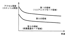
図1を参照して、車両に搭載されたパワートレーン100のエンジン200の出力トルクは、トルクコンバータ300を介して、前後進切換装置400を有する無段変速機500に入力される。無段変速機500の出力は、減速歯車600および差動歯車装置700に伝達され、左右の駆動輪800へ分配される。パワートレーン100は、後述するECU(Electronic Control Unit)900により制御される。なお、エンジン200の代わりにもしくは加えて、電動モータを駆動源として用いるようにしてもよい。
<First Embodiment>
Referring to FIG. 1, the output torque of
トルクコンバータ300は、エンジン200のクランク軸に連結されたポンプインペラ302と、タービン軸304を介して前後進切換装置400に連結されたタービンランナ306とから構成されている。ポンプインペラ302およびタービンランナ306の間にはロックアップクラッチ308が設けられている。ロックアップクラッチ308は、係合側油室および解放側油室に対する油圧供給が切換えられることにより、係合または解放されるようになっている。
The
ロックアップクラッチ308が完全係合させられることにより、ポンプインペラ302およびタービンランナ306は一体的に回転させられる。ポンプインペラ302には、無段変速機500を変速制御したり、ベルト挟圧力を発生させたり、各部に潤滑のための作動油を供給したりするための油圧を発生する機械式のオイルポンプ310が設けられている。
When the
前後進切換装置400は、ダブルピニオン型の遊星歯車装置から構成されている。トルクコンバータ300のタービン軸304はサンギヤ402に連結されている。無段変速機500の入力軸502はキャリア404に連結されている。キャリア404とサンギヤ402とはフォワードクラッチ406を介して連結されている。リングギヤ408は、リバースブレーキ410を介してハウジングに固定される。フォワードクラッチ406およびリバースブレーキ410は油圧シリンダによって摩擦係合させられる。フォワードクラッチ406の入力回転数は、タービン軸304の回転数、すなわちタービン回転数NTと同じである。
The forward /
フォワードクラッチ406が係合させられるとともに、リバースブレーキ410が解放されることにより、前後進切換装置400は前進用係合状態となる。この状態で、前進方向の動力が無段変速機500に伝達される。リバースブレーキ410が係合させられるとともにフォワードクラッチ406が解放されることにより、前後進切換装置400は後進用係合状態となる。この状態で、入力軸502はタービン軸304に対して逆方向へ回転させられる。これにより、後進方向の動力が無段変速機500に伝達される。
When the
すなわち、フォワードクラッチ406もしくはリバースブレーキ410が係合することにより、エンジン200から出力された動力が駆動輪800に伝達される。フォワードクラッチ406およびリバースブレーキ410が共に解放されると、前後進切換装置400は動力伝達を遮断するニュートラル状態になる。
That is, when the
なお、前後進切換装置400を、無段変速機500と駆動輪800との間に配置するようにしてもよい。
The forward /
無段変速機500には、入力軸502に設けられたプライマリプーリ504と、出力軸506に設けられたセカンダリプーリ508と、これらのプーリに巻き掛けられた金属ベルト510とがさらに設けられる。各プーリと金属ベルト510との間の摩擦力を利用して、動力伝達が行われる。
The continuously
各プーリは溝幅が可変であるように、油圧シリンダ(シーブ)から構成されている。プライマリプーリ504の油圧シリンダ、すなわちプライマリシーブの油圧が制御されることにより、各プーリの溝幅が変化する。これにより、各プーリの有効径が変更され、ギヤ比GR(=プライマリプーリ回転数NIN/セカンダリプーリ回転数NO)が連続的に変化させられる。なお、金属ベルト510の代わりにチェーンを用いるようにしてもよい。
Each pulley is composed of a hydraulic cylinder (sheave) so that the groove width is variable. By controlling the hydraulic pressure of the hydraulic cylinder of the
図2に示すように、ECU900には、エンジン回転数センサ902、タービン回転数センサ904、車速センサ906、スロットル開度センサ908、冷却水温センサ910、油温センサ912、アクセル開度センサ914、フットブレーキスイッチ916、ポジションセンサ918、プライマリプーリ回転数センサ922およびセカンダリプーリ回転数センサ924が接続されている。
As shown in FIG. 2, the
エンジン回転数センサ902は、エンジン200の回転数(エンジン回転数)NEを検出する。タービン回転数センサ904は、タービン軸304の回転数(タービン回転数)NTを検出する。車速センサ906は、車速Vを検出する。スロットル開度センサ908は、電子スロットルバルブの開度TAを検出する。冷却水温センサ910は、エンジン200の冷却水温TWを検出する。油温センサ912は、無段変速機500の作動に用いられる作動油の温度(以下、油温とも記載する)THOを検出する。アクセル開度センサ914は、アクセルペダルの開度PAを検出する。フットブレーキスイッチ916は、フットブレーキの操作の有無を検出する。ポジションセンサ918は、シフトポジションと対応する位置に設けられた接点がONであるかOFFであるかを判別することにより、シフトレバー920のポジションPSHを検出する。プライマリプーリ回転数センサ922は、プライマリプーリ504の回転数(入力軸回転数)NINを検出する。セカンダリプーリ回転数センサ924は、セカンダリプーリ508の回転数(出力軸回転数)NOを検出する。各センサの検出結果を表す信号が、ECU900に送信される。タービン回転数NTは、フォワードクラッチ406が係合された前進走行時にはプライマリプーリ回転数NINと一致する。車速Vは、セカンダリプーリ回転数NOと対応した値になる。したがって、本実施の形態においては、車速Vを示す物理量としてセカンダリプーリ回転数NOが用いられる。なお、車速センサ906により検出された車速Vを用いるようにしてもよい。
The
本実施の形態においてアクセル開度PAおよびスロットル開度TAは共に百分率で表わされる。アクセル開度PAおよびスロットル開度TAが全閉状態である場合、アクセル開度PAおよびスロットル開度TAは「0%」と表わされる。アクセル開度PAおよびスロットル開度TAが全開状態である場合、アクセル開度PAおよびスロットル開度TAは「100%」と表わされる。アクセル開度PAおよびスロットル開度TAは共に百分率で表わされるため、アクセル開度PAおよびスロットル開度TAを直接比較することができる。すなわち、アクセル開度PAとスロットル開度TAとは同じ物理量であるとみなされる。 In the present embodiment, both the accelerator opening PA and the throttle opening TA are expressed as percentages. When the accelerator opening PA and the throttle opening TA are in the fully closed state, the accelerator opening PA and the throttle opening TA are expressed as “0%”. When the accelerator opening PA and the throttle opening TA are fully open, the accelerator opening PA and the throttle opening TA are expressed as “100%”. Since both the accelerator opening PA and the throttle opening TA are expressed as percentages, the accelerator opening PA and the throttle opening TA can be directly compared. That is, the accelerator opening PA and the throttle opening TA are regarded as the same physical quantity.
ECU900は、CPU(Central Processing Unit)、メモリおよび入出力インターフェースなどを含む。CPUはメモリに記憶されたプログラムに従って信号処理を行なう。これにより、エンジン200の出力制御、無段変速機500の変速制御、ベルト挟圧力制御、フォワードクラッチ406の係合/解放制御およびリバースブレーキ410の係合/解放制御などを実行する。
エンジン200の出力制御は電子スロットルバルブ1000、燃料噴射装置1100、点火装置1200などによって行なわれる。無段変速機500の変速制御、ベルト挟圧力制御、フォワードクラッチ406の係合/解放制御およびリバースブレーキ410の係合/解放制御は、油圧制御回路2000によって行なわれる。
Output control of the
図3を参照して、ECU900に実装される車両の制御システムの構成について説明する。図5中の「F」は駆動力を、「TE」はエンジントルクを、「PA」はアクセル開度を、「TA」はスロットル開度を、「NO」はセカンダリプーリ回転数を示す。駆動力の単位は「N(ニュートン)」である。なお、以下に説明する各構成の機能は、ハードウエアにより実現するようにしてもよく、ソフトウエア(プログラム)により実現するようにしてもよく、ハードウエアとソフトウエアとの組み合わせにより実現するようにしてもよい。
With reference to FIG. 3, the configuration of a vehicle control system implemented in
制御システムは、パワートレーンドライバモデル3000、クルーズコントロールシステム3010およびパワートレーンマネージャ3100、エンジン制御システム3200および油圧制御システム3300を含む。
The control system includes a power
パワートレーンドライバモデル3000は、ドライバの操作に基づいて、車両の目標駆動力を設定するために用いられるモデル(関数)である。本実施の形態においては、実験およびシミュレーションの結果などに基づいて予め定められたマップに従って、アクセル開度PAならびに車速V(セカンダリプーリ回転数NO)から、駆動力設定部3002により目標駆動力が設定される。
The power
クルーズコントロールシステム3010は、車両の挙動に応じて目標駆動力を自動的に設定する。たとえば、クルーズコントロールシステム3010は、ドライバにより設定された車速Vを維持するために必要な目標駆動力を、設計者により予め作成されたマップなどに基づいて自動的に設定する。
The
その他、車両の挙動を安定化するためのVSC(Vehicle Stability Control)、TRC(TRaction Control)、ABS(Anti lock Brake System)、EPS(Electric Power Steering)などの制御システムを搭載するようにしてもよい。VSCは、前後輪が横滑りしそうな状態をセンサが検出して場合において、各輪のブレーキ油圧および車両の目標駆動力などの最適値を自動的に設定し、車両の安定性を確保する制御である。TRCは、滑りやすい路面での発進時および加速時に、駆動輪の空転をセンサが感知すると、各輪のブレーキ油圧および車両の目標駆動力などの最適値を自動的に設定し、最適な駆動力を確保する制御である。ABSは、ブレーキ油圧の最適値を自動的に設定し、車輪のロックを防止する制御システムである。EPSは、電動モータの力によってステアリングホイールの操舵をアシストする制御システムである。 In addition, control systems such as VSC (Vehicle Stability Control), TRC (TRaction Control), ABS (Antilock Brake System), EPS (Electric Power Steering), etc. for stabilizing the behavior of the vehicle may be installed. . VSC is a control that ensures the stability of the vehicle by automatically setting optimum values such as the brake hydraulic pressure of each wheel and the target driving force of the vehicle when the sensor detects that the front and rear wheels are likely to skid. is there. TRC automatically sets optimal values such as brake hydraulic pressure of each wheel and target driving force of the vehicle when the sensor detects idling of the driving wheel when starting and accelerating on a slippery road surface. It is the control to ensure. ABS is a control system that automatically sets an optimum value of brake hydraulic pressure and prevents wheel lock. EPS is a control system that assists steering of a steering wheel by the force of an electric motor.
パワートレーンマネージャ3100は、パワートレーンドライバモデル3000およびクルーズコントロールシステム3010から入力される目標駆動力を調整する駆動力調停部3102を備える。たとえば、最も大きい目標駆動力を選択するように、パワートレーンドライバモデル3000およびクルーズコントロールシステム3010から入力される目標駆動力が調停される。なお、車両の運転状態に応じて目標駆動力の調停方法を変更するようにしてもよい。最も小さい目標駆動力を選択するようにしてもよい。
The
駆動力調停部3102において調停された目標駆動力は、トルク変換部3104において目標エンジントルクに変換される。たとえば、目標駆動力と車輪の半径との積を、無段変速機500の現在のギヤ比などで除算することにより、目標駆動力が目標エンジントルクに変換される。なお、駆動力をトルクに変換する方法には周知の一般的な技術を利用すればよいため、ここではその詳細な説明は繰返さない。
The target driving force adjusted by the driving
トルク変換部3104において目標駆動力から変換された目標エンジントルクは、エンジン制御システム3200に入力される。エンジン制御システム3200は、パワートレーンマネージャ3100から入力された目標エンジントルクを実現するように、電子スロットルバルブ1000、点火時期、EGR(Exhaust Gas Recirculation)バルブなど、エンジン200の出力トルクを制御するためにエンジン200に設けられた機器(アクチュエータ)を制御する。
The target engine torque converted from the target driving force in the
エンジン200は、目標エンジントルクに加えて、エンジン200の補機(オルタネータ、ウォーターポンプおよびオイルポンプなど)を駆動するために必要なパワーを実現するトルクを出力するように制御される。なお、パワーの単位は「W(ワット)」である。
パワートレーンマネージャ3100は、目標エンジントルクの他、無段変速機500の目標入力回転数NINT、すなわちプライマリプーリ回転数NINの目標回転数を設定する機能を有する。
In addition to the target engine torque, the
目標入力回転数NINTは、アクセル開度センサ914により検出されたアクセル開度PA、および、クルーズコントロールシステム3010により設定された目標駆動力から変換されたスロットル開度TAのうちのいずれか一方に応じて設定される。
The target input rotational speed NINT depends on one of the accelerator opening PA detected by the
クルーズコントロールシステム3010により設定された目標駆動力は、スロットル変換部3110によりスロットル開度TAに変換される。クルーズコントロールシステム3010により設定された目標駆動力は、たとえば、実験およびシミュレーションの結果に応じて開発者により作成されたマップに従って、スロットル開度TAに変換される。なお、目標駆動力をスロットル開度TAに変換する方法はこれに限らない。
The target driving force set by the
アクセル開度センサ914により検出されたアクセル開度PA、および、クルーズコントロールシステム3010により設定された目標駆動力から変換されたスロットル開度TAは、スロットル調停部3112により調停される。スロットル調停部3112以降の処理において、アクセル開度PAは、スロットル開度TAとして取り扱われる。スロットル調停部3112は、たとえば、最も大きいスロットル開度TAを選択する。なお、車両の運転状態に応じてスロットル開度TAの調停方法を変更するようにしてもよい。最も小さいスロットル開度TAを選択するようにしてもよい。また、アクセル開度PAに応じて設定された目標駆動力から変換されたスロットル開度TAと、クルーズコントロールシステム3010により設定された目標駆動力から変換されたスロットル開度TAとを調停するようにしてもよい。
The throttle opening degree PA detected by the accelerator
スロットル調停部3112により選択されたスロットル開度TAは、目標入力回転数設定部3114に入力される。目標入力回転数設定部3114は、スロットル開度TAおよび車速Vをパラメータに有するマップに従って、目標入力回転数NINTを設定する。目標入力回転数設定部3114に入力されるスロットル開度TAは、アクセル開度PAと同じもの、または、目標駆動力から変換されたものである。したがって、目標入力回転数設定部3114は、アクセル開度PAおよび目標駆動力のうちのいずれか一方に応じて目標入力回転数NINTを設定する。
The throttle opening degree TA selected by the
スロットル調停部3112により、アクセル開度センサ914により検出されたアクセル開度PA(スロットル開度TA)が選択された場合、目標入力回転数NINTは、図6に示すマップに従って、アクセル開度PA(スロットル開度TA)および車速Vに応じてリニアシフトモードまたは燃費最適モードで設定される。
When the
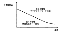
図4に示すように、大きいアクセル開度PA(スロットル開度TA)を含む第1の領域にアクセル開度PAがある場合、リニアシフトモードで目標入力回転数NINTが設定される。第1の領域が含むアクセル開度PAよりも小さいアクセル開度PAを含む第2の領域にアクセル開度PAがある場合、リニアシフトモードとは異なる燃費最適モードで目標入力回転数NINTが設定される。 As shown in FIG. 4, when the accelerator opening PA is in the first region including the large accelerator opening PA (throttle opening TA), the target input rotational speed NINT is set in the linear shift mode. When the accelerator opening PA is in the second area including the accelerator opening PA smaller than the accelerator opening PA included in the first area, the target input rotational speed NINT is set in the fuel efficiency optimal mode different from the linear shift mode. The
リニアシフトモードでは、車速Vが大きくなるほど大きくなるように目標入力回転数NINTが定められる。燃費最適モードでは、リニアシフトモードに比べて、燃料消費量が低減するように目標入力回転数NINTが定められる。リニアシフトモードおよび燃費最適モードについては、後でさらに詳細に説明する。 In the linear shift mode, the target input rotational speed NINT is determined so as to increase as the vehicle speed V increases. In the fuel efficiency optimum mode, the target input rotational speed NINT is determined so that the fuel consumption is reduced as compared with the linear shift mode. The linear shift mode and the fuel efficiency optimal mode will be described in more detail later.
同様に、スロットル調停部3112により、クルーズコントロールシステム3010により設定された目標駆動力から変換されたスロットル開度TAが選択された場合、目標入力回転数NINTは、図5に示すマップに従って、目標駆動力から変換されたスロットル開度TAおよび車速Vに応じてリニアシフトモードまたは燃費最適モードで設定される。なお、図5に示すマップでは、説明のため、スロットル開度TAの代わりに、スロットル開度TAに変換される前の目標駆動力を示す。
Similarly, when the throttle opening degree TA converted from the target driving force set by the
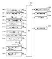
図5に示すように、大きい目標駆動力(スロットル開度TA)を含む第3の領域に目標駆動力がある場合はリニアシフトモードで目標入力回転数NINTが設定される。第3の領域が含む目標駆動力よりも小さい目標駆動力を含む第4の領域に目標駆動力がある場合は燃費最適モードで目標入力回転数NINTが設定される。 As shown in FIG. 5, when the target driving force is in the third region including the large target driving force (throttle opening TA), the target input rotational speed NINT is set in the linear shift mode. When the target driving force is present in the fourth region including the target driving force smaller than the target driving force included in the third region, the target input rotational speed NINT is set in the fuel efficiency optimal mode.
目標入力回転数設定部3114には、アクセル開度PAと同じであるスロットル開度TAまたは目標駆動力から変換されたスロットル開度TAのうちのいずれか一方が入力される。その結果として、目標入力回転数設定部3114は、図4に示す第1の領域にアクセル開度PAがある場合および図5に示す第3の領域に目標駆動力がある場合のうちのいずれか一方の場合に、リニアシフトモードで目標入力回転数NINTを設定する。
The target input rotation
本実施の形態では、アクセル開度PA(スロットル開度TA)の方が、目標駆動力(目標駆動力から変換されたスロットル開度TA)よりも、リニアシフトモードで目標入力回転数NINTを設定するため条件を満たし易いように種々のしきい値が設定される。 In this embodiment, the accelerator opening PA (throttle opening TA) sets the target input speed NINT in the linear shift mode rather than the target driving force (throttle opening TA converted from the target driving force). Therefore, various threshold values are set so as to easily satisfy the conditions.
たとえば、図6に示すように、第1の領域の下端を規定する境界線は、破線で示される、第3の領域の下端を規定する境界線よりも低くなるように定められる。図6においては、図5に示す第3の領域の下端を規定する境界線をスロットル開度TAに変換した線を破線で示す。 For example, as shown in FIG. 6, the boundary line that defines the lower end of the first region is determined to be lower than the boundary line that defines the lower end of the third region, which is indicated by a broken line. In FIG. 6, a line obtained by converting the boundary line defining the lower end of the third region shown in FIG. 5 into the throttle opening degree TA is indicated by a broken line.
これにより、ドライバがアクセルペダルを操作した場合には、ドライバの操作に対応した制御をより実現し易くすることができる。 Thereby, when the driver operates the accelerator pedal, it is possible to more easily realize the control corresponding to the operation of the driver.
図7に示すように、リニアシフトモードでは、車速Vと目標入力回転数NINTとが比例するように、目標入力回転数NINTが設定される。より具体的には、たとえば、アクセル開度PA(スロットル開度TA)または目標駆動力(目標駆動力から変換されたスロットル開度TA)が安定している場合は、無段変速機500のギヤ比が固定される。目標入力回転数NINTが車速に比例して増大しながら、無段変速機500のギヤ比が小さくなるように(無段変速機500がアップシフトするように)してもよい。
As shown in FIG. 7, in the linear shift mode, the target input rotational speed NINT is set so that the vehicle speed V is proportional to the target input rotational speed NINT. More specifically, for example, when the accelerator opening PA (throttle opening TA) or the target driving force (throttle opening TA converted from the target driving force) is stable, the gear of the continuously
リニアシフトモードで目標入力回転数NINTを設定する際、トルクコンバータ300の速度比(出力軸回転数/入力軸回転数)を考慮して、エンジン回転数NEが車速に比例して増大するように目標入力回転数NINTが設定される。 When setting the target input speed NINT in the linear shift mode, the engine speed NE is increased in proportion to the vehicle speed in consideration of the speed ratio of the torque converter 300 (output shaft speed / input shaft speed). A target input rotational speed NINT is set.
図3に戻って、リニアシフトモードで設定された目標入力回転数NINTは、第1補正部3121および第2補正部3122により、車両の運転状態に応じて補正される。
Returning to FIG. 3, the target input rotational speed NINT set in the linear shift mode is corrected by the
第1補正部3121は、リニアシフトモードで目標入力回転数NINTが定められる状態において、エンジン200の出力パワーを増大しても駆動力調停部3102において選択された目標駆動力を実現できない場合(実現できない状況に近い場合を含む)、目標入力回転数NINTを増大する。
The
たとえば、無段変速機500の現在のギヤ比によって得られる駆動力の最大値と予め定められた定数Kとの積が、駆動力調停部3102において選択された目標駆動力よりも小さい場合、目標入力回転数NINTが増大される。同様に、アクセル開度PAが急増した場合、目標入力回転数NINTが増大される。たとえば、アクセル開度PAの変化率がしきい値以上であり、かつアクセル開度PAがしきい値以上であると、目標入力回転数NINTが増大される。
For example, if the product of the maximum value of the driving force obtained by the current gear ratio of continuously
目標入力回転数NINTは、駆動力調停部3102において選択された目標駆動力を実現できる回転数まで増大される。これにより、無段変速機500をダウンシフトすることができる。そのため、必要な駆動力を確保することができる。
The target input rotational speed NINT is increased to a rotational speed at which the target driving force selected by the driving
本実施の形態では、アクセル開度PAの方が、目標駆動力よりも、目標入力回転数NINTを増大するように補正するため条件を満たし易いように定数Kおよび種々のしきい値が設定される。 In the present embodiment, a constant K and various threshold values are set so that the accelerator opening PA is more easily satisfied than the target driving force in order to correct the target input rotational speed NINT to increase. The
なお、定数Kが1より大きくなるように設定することにより、駆動力の実現よりもプライマリプーリ回転数NINの回転数の低回転化を優先することができる。この場合、実現される駆動力の精度が悪化したことを、信号などを用いてパワートレーンドライバモデル3000またはクルーズコントロールシステム3010に通知し、フィードバック制御および積分演算などを中断することが好ましい。
Note that by setting the constant K to be greater than 1, priority can be given to lowering the rotation speed of the primary pulley rotation speed NIN than to realizing the driving force. In this case, it is preferable to notify the power
第2補正部3122は、リニアシフトモードで目標入力回転数NINTが定める状態において、無段変速機500のプライマリプーリ回転数NINがしきい値よりも高い状態が予め定められた時間以上継続した場合、目標入力回転数NINTを小さくする。これにより、エンジン200が発する音によりドライバに与える不快感を和らげることができる。
When the target input rotational speed NINT is determined in the linear shift mode, the
第1補正部3121または第2補正部3122によって目標入力回転数NINTを補正する場合、目標入力回転数NINTの変化率を制限することが好ましい。目標入力回転数NINTの変化率を制限することにより、プライマリプーリ回転数NINの急変を防ぐことができる。
When the target input rotation speed NINT is corrected by the
燃費最適モードでは、目標駆動力と消費燃料マップより定まる、燃費が最適となる回転数が、目標入力回転数NINTとして設定される。燃費等を考慮した静的な変速線によって目標入力回転数NINTを規定してもよい。 In the fuel efficiency optimal mode, the rotational speed at which the fuel efficiency is optimal, which is determined from the target driving force and the fuel consumption map, is set as the target input rotational speed NINT. The target input rotational speed NINT may be defined by a static shift line considering fuel consumption and the like.
燃費最適モードで設定される目標入力回転数NINTは、要するに、現在の車速Vにおいて、調停の結果選択された目標駆動力を実現できるエンジンの作動点のうち、燃料消費量が最も小さい回転数である。具体的には、図8に示すように、実験およびシミュレーションなどの結果に応じて開発者により規定される最適燃費線と等パワー線との交点における回転数が目標入力回転数NINTとして設定される。 In short, the target input speed NINT set in the fuel efficiency optimal mode is the speed at which the fuel consumption is the smallest among the operating points of the engine that can achieve the target driving force selected as a result of the arbitration at the current vehicle speed V. is there. Specifically, as shown in FIG. 8, the rotational speed at the intersection of the optimum fuel consumption line and the equal power line defined by the developer according to the results of experiments and simulations is set as the target input rotational speed NINT. .
最適燃費線と等パワー線との交点から目標回転数NINTを逐次演算する代わりに、本実施の形態においては、最適燃費線と等パワー線との交点における回転数が目標入力回転数NINTとして規定されたマップが用いられる。 Instead of sequentially calculating the target rotational speed NINT from the intersection of the optimal fuel consumption line and the equal power line, in this embodiment, the rotational speed at the intersection of the optimal fuel consumption line and the equal power line is defined as the target input rotational speed NINT. Map is used.
図9に示すように、上述の目標入力回転数NINTは、スロットル開度TAと車速Vとをパラメータに有するマップに従って設定される。図9における矢印は、スロットル開度TA(アクセル開度PA)が大きいほど、大きい目標入力回転数NINTが設定されることを示す。 As shown in FIG. 9, the target input rotational speed NINT is set according to a map having the throttle opening degree TA and the vehicle speed V as parameters. The arrows in FIG. 9 indicate that a larger target input rotational speed NINT is set as the throttle opening degree TA (accelerator opening degree PA) is larger.
目標入力回転数NINTを設定するために用いられるマップは、たとえば、実験およびシミュレーションの結果に基づいて開発者により予め作成される。マップを用いることにより、燃費が最適になるという要件以外にも、車速Vと目標駆動力とによって目標入力回転数NINTが一義的に定まる要件を考慮して、目標入力回転数NINTを設定することができる。 The map used for setting the target input rotational speed NINT is created in advance by the developer based on the results of experiments and simulations, for example. The target input speed NINT is set in consideration of the requirement that the target input speed NINT is uniquely determined by the vehicle speed V and the target driving force in addition to the requirement that the fuel consumption is optimized by using the map. Can do.
燃費最適モードでは、目標駆動力の変化量に対するスロットル開度の変化量が大きい領域では、目標駆動力の変化量に対するスロットル開度の変化量が小さい領域に比べて、無段変速機500のギヤ比の変化量が小さくなるように、目標入力回転数NINTが設定される。
In the fuel efficiency optimum mode, the gear of the continuously
具体的には、スロットル開度TA(アクセル開度PA)と車速Vとが、図10において破線で囲まれる領域内にある場合、無段変速機500のギヤ比が上限値に固定されるように、目標入力回転数NINTが定められる。たとえば、スロットル開度TA(アクセル開度PA)と車速Vとが、図10において破線で囲まれる領域内にある場合、図9に示す上限回転数以上の目標入力回転数NINTが設定されるようにマップが定められるとともに、目標入力回転数NINTを上限回転数により制限することによって、無段変速機500のギヤ比が上限値に固定される。これにより、目標入力回転数NINTのハンチングを防止することができる。
Specifically, when throttle opening degree TA (acceleration opening degree PA) and vehicle speed V are within the region surrounded by the broken line in FIG. 10, the gear ratio of continuously
図3に戻って、燃費最適モードで目標入力回転数NINTが定められる場合、スロットル調停部3112により選択されたスロットル開度TA(アクセル開度PA)に、補機の負荷に相当するスロットル開度TAが加えられたスロットル開度TAを用いて、目標入力回転数NINTが設定される。すなわち、燃費最適モードでは、エンジン200の補機の負荷分だけ大きいアクセル開度PAおよび補機の負荷分だけ大きい目標駆動力のうちのいずれか一方に応じて目標入力回転数NINTが設定される。
Returning to FIG. 3, when the target input rotational speed NINT is determined in the fuel efficiency optimal mode, the throttle opening corresponding to the load of the auxiliary machine is added to the throttle opening TA (accelerator opening PA) selected by the
補機の負荷に相当するスロットル開度TAは、スロットル変換部3116により、補機を駆動するために必要なパワーから変換される。たとえば、実験およびシミュレーションなどに基づいて開発者が予め作成したマップに従って、補機を駆動するために必要なパワーがスロットル開度TAに換算される。なお、エンジン200の補機の負荷(補機を駆動するために必要なパワー)を算出する方法は、周知の一般的な技術を利用すればよいため、ここではその詳細な説明は繰り返さない。
The throttle opening degree TA corresponding to the load of the auxiliary machine is converted from the power necessary for driving the auxiliary machine by the
パワートレーンマネージャ3100により設定された目標入力回転数NINTは、油圧制御システム3300に入力される。油圧制御システム3300は、実際のプライマリプーリ回転数NINが、パワートレーンマネージャ3100により設定された目標入力回転数NINTになるように、油圧制御回路2000を用いて無段変速機500のギヤ比を制御する。
The target input rotational speed NINT set by the
以上のように、本実施の形態によれば、アクセル開度PAが小さい場合には、燃費を重視して目標入力回転数NINTが定められる一方で、アクセル開度PAが大きい場合、すなわち、ドライバが加速を要求している場合には、車速Vと共に増大するように目標入力回転数NINTが定められる。無段変速機500の入力軸回転数(プライマリプーリ回転数)NINは、設定された目標入力回転数NINTになるように制御される。これにより、無段変速機500に連結されたエンジン200の回転数NEが車速Vと共に増大するというドライバの期待に応えることができる。クルーズコントロールシステム3010により、アクセル開度PAの代わりに目標駆動力が用いられる場合、アクセル開度PAを用いる場合と同様の態様で目標入力回転数NINTが定められる。すなわち、目標駆動力が小さい場合には、燃費を重視して目標入力回転数NINTが定められる一方で、目標駆動力が大きい場合、すなわち、加速時には、車速Vと共に増大するように目標入力回転数NINTが定められる。無段変速機500の入力軸回転数NINは、設定された目標入力回転数NINTになるように制御される。これにより、アクセルペダルは操作されずに目標駆動力が設定される場合であっても、エンジン回転数NEが車速Vと共に増大するというドライバの期待に応えることができる。その結果、ドライバビリティを向上することができる。
As described above, according to the present embodiment, when the accelerator opening PA is small, the target input rotational speed NINT is determined with emphasis on fuel efficiency, while when the accelerator opening PA is large, that is, the driver Is required to accelerate, the target input rotational speed NINT is determined so as to increase with the vehicle speed V. The input shaft rotational speed (primary pulley rotational speed) NIN of the continuously
<第2の実施の形態>
以下、第2の実施の形態について説明する。図11に示すように、本実施の形態においては、リニアシフトモードで目標入力回転数NINTが設定される第1の領域と、燃費最適モードで目標入力回転数NINTが設定される第2の領域とが離間している。
<Second Embodiment>
Hereinafter, a second embodiment will be described. As shown in FIG. 11, in the present embodiment, the first region where the target input rotational speed NINT is set in the linear shift mode and the second region where the target input rotational speed NINT is set in the fuel efficiency optimal mode. Are separated from each other.
スロットル調停部3112により、アクセル開度センサ914により検出されたアクセル開度PA(スロットル開度TA)が選択され、かつ、第1の領域および第2領域とは異なる第5の領域にアクセル開度PAがある場合、リニアシフトモードで定められた目標入力回転数NINTと、燃費最適モードで定められた目標入力回転数NINTとから目標入力回転数NINTを定めるように、アクセル開度PAに応じて目標入力回転数NINTが定められる。
The
同様に、図12に示すように、リニアシフトモードで目標入力回転数NINTが設定される第3の領域と、燃費最適モードで目標入力回転数NINTが設定される第4の領域とが離間している。 Similarly, as shown in FIG. 12, the third area where the target input speed NINT is set in the linear shift mode and the fourth area where the target input speed NINT is set in the fuel efficiency optimal mode are separated from each other. ing.
スロットル調停部3112により、クルーズコントロールシステム3010により設定された目標駆動力から変換されたスロットル開度TAが選択され、かつ、第3の領域および第4領域とは異なる第6の領域に目標駆動力(スロットル開度TA)がある場合、リニアシフトモードで定められた目標入力回転数NINTと、燃費最適モードで定められた目標入力回転数NINTとから目標入力回転数NINTを定めるように、目標駆動力に応じて目標入力回転数NINTが設定される。
A throttle opening degree TA converted from the target driving force set by the
その他の構造については、前述の第1の実施の形態と同じである。したがって、ここではそれらの詳細な説明は繰り返さない。 Other structures are the same as those in the first embodiment. Therefore, detailed description thereof will not be repeated here.
以下、目標入力回転数NINTを設定する方法についてさらに詳細に説明する。目標入力回転数NINTは、下記の式に基づいて算出される。 Hereinafter, a method for setting the target input rotation speed NINT will be described in more detail. The target input rotation speed NINT is calculated based on the following equation.
NINT=NINT1×α+NINT2×(1−α)・・・(1)
式1において、「NINT1」は、リニアシフトモードで設定される目標入力回転数NINTを示す。「NINT2」は、燃費最適モードで設定される目標入力回転数NINTを示す。「α」は、0〜1までの係数であって、目標入力回転数NINTに対するリニアシフトモードの寄与度を示す。
NINT = NINT 1 × α + NINT 2 × (1−α) (1)
In Expression 1, “NINT 1 ” indicates the target input rotational speed NINT set in the linear shift mode. “NINT 2 ” indicates a target input rotational speed NINT set in the fuel efficiency optimal mode. “Α” is a coefficient from 0 to 1, and indicates the degree of contribution of the linear shift mode to the target input rotational speed NINT.
本実施の形態において、リニアシフトモードで設定される目標入力回転数NINT1、および燃費最適モードで設定される目標入力回転数NINT2は、常時算出される。「α」は、前述した第1の領域および第3の領域で「1」であり、前述した第2の領域および第4の領域で「0」であり、前述した第5の領域および第6の領域において「0」より大きく「1」より小さい値であるように規定されている。 In the present embodiment, the target input rotation speed NINT 1 set in the linear shift mode and the target input rotation speed NINT 2 set in the fuel efficiency optimal mode are always calculated. “Α” is “1” in the first region and the third region described above, “0” in the second region and the fourth region described above, and the fifth region and the sixth region described above. In this area, the value is defined to be larger than “0” and smaller than “1”.
このようにすれば、リニアシフトモードで目標入力回転数NINTが設定される領域と、燃費最適モードで目標入力回転数NINTが設定される領域とのうちの、一方の領域から他方の領域にアクセル開度PAまたは目標駆動力が移行する場合に、目標入力回転数NINTを緩やかに変化させることができる。 In this case, the accelerator is moved from one region to the other region in the region where the target input rotational speed NINT is set in the linear shift mode and the region where the target input rotational speed NINT is set in the fuel efficiency optimal mode. When the opening degree PA or the target driving force shifts, the target input rotation speed NINT can be changed gently.
なお、式1を用いる代わりに、目標入力回転数NINTが所定の変化量ずつ変化するような処理を実行してもよい。 Instead of using Equation 1, a process in which the target input rotational speed NINT changes by a predetermined change amount may be executed.
<第3の実施の形態>
第1,2の実施の形態において、図13に示すように、アクセル開度PAおよびスロットル開度TAの代わりに、目標駆動力を用いて目標入力回転数NINTを設定するようにしてもよい。この場合、前述した第1の実施の形態および第2の実施の形態において説明したマップのパラメータ等として用いられていたアクセル開度PAおよびスロットル開度TAを、目標駆動力に換算して用いればよい。
<Third Embodiment>
In the first and second embodiments, as shown in FIG. 13, the target input rotational speed NINT may be set using a target driving force instead of the accelerator opening PA and the throttle opening TA. In this case, if the accelerator opening PA and the throttle opening TA used as the parameters of the maps described in the first embodiment and the second embodiment are converted into the target driving force and used. Good.
本実施の形態において、燃費最適モードで目標入力回転数NINTが定められる場合、補機の負荷に相当する駆動力が加えられた目標駆動力を用いて、目標入力回転数NINTが設定される。補機の負荷に相当する駆動力は、駆動力変換部3118により、補機を駆動するために必要なパワーから変換される。
In the present embodiment, when the target input rotational speed NINT is determined in the fuel efficiency optimal mode, the target input rotational speed NINT is set using the target driving force applied with the driving force corresponding to the load of the auxiliary machine. The driving force corresponding to the load of the auxiliary machine is converted from the power necessary for driving the auxiliary machine by the driving
<第4の実施の形態>
第1〜3の実施の形態において、図14に示すように、エンジン200に加えて、第1モータジェネレータ201、第2モータジェネレータ202を搭載したハイブリッド車を用いてもよい。ハイブリッド車は、エンジン200および第2モータジェネレータ202のうちの少なくともいずれか一方からの駆動力により走行する。
<Fourth embodiment>
In the first to third embodiments, as shown in FIG. 14, a hybrid vehicle in which a
エンジン200、第1モータジェネレータ201および第2モータジェネレータ202は、動力分割機構204を介して接続されている。エンジン200が発生するトルクは、動力分割機構204により、2経路に分割される。一方の経路はトルクを無段変速機500に伝達する。他方の経路は、トルクを第1モータジェネレータ201に伝達する。
第1モータジェネレータ201は、三相交流回転電機である。第1モータジェネレータ201は、動力分割機構204により分割されたエンジン200のトルクにより駆動されて、発電する。第1モータジェネレータ201により発電された電力は、車両の走行状態や、バッテリ(図示せず)の残存容量の状態に応じて使い分けられる。たとえば、通常走行時では、第1モータジェネレータ201により発電された電力はそのまま第2モータジェネレータ202を駆動させる電力となる。一方、バッテリの残存容量が予め定められた値よりも低い場合、第1モータジェネレータ201により発電された電力は、バッテリに蓄えられる。
第2モータジェネレータ202は、三相交流回転電機である。第2モータジェネレータ202は、バッテリに蓄えられた電力および第1モータジェネレータ201により発電された電力のうちの少なくともいずれかの電力により駆動する。
第2モータジェネレータ202の出力トルクは、無段変速機500に入力される。これにより、第2モータジェネレータ202はエンジン200をアシストしたり、第2モータジェネレータ202からの駆動力により車両を走行させたりする。
The output torque of the
プラグイン車両の回生制動時には、第2モータジェネレータ202が発電機として駆動される。これにより第2モータジェネレータ202は、制動エネルギを電力に変換する回生ブレーキとして作動する。第2モータジェネレータ202により発電された電力は、バッテリに蓄えられる。
During regenerative braking of the plug-in vehicle, the
動力分割機構204は、サンギヤと、ピニオンギヤと、キャリアと、リングギヤとを含む遊星歯車から構成される。ピニオンギヤは、サンギヤおよびリングギヤと係合する。キャリアは、ピニオンギヤが自転可能であるように支持する。サンギヤは第1モータジェネレータ201の回転軸に連結される。キャリアはエンジン200のクランクシャフトに連結される。リングギヤは第2モータジェネレータ202の回転軸および無段変速機500の入力軸に連結される。
Power split
エンジン200、第1モータジェネレータ201および第2モータジェネレータ202が、遊星歯車からなる動力分割機構204を介して連結されることで、図15に示すように、エンジン200、第1モータジェネレータ201および第2モータジェネレータ202の回転数は、共線図において直線で結ばれる関係になる。したがって、エンジン回転数NEは、無段変速機500の入力回転数NINと、第1モータジェネレータ201の回転数との影響を受けて定まる。
The
このようなハイブリッド車において、リニアシフトモードで目標入力回転数NINTを設定する際、エンジン回転数NEが車速Vに比例するようにするとともに、第1モータジェネレータおよび第2モータジェネレータによる電力の収支が最適となるように、目標入力回転数NINTを設定することが好ましい。 In such a hybrid vehicle, when setting the target input rotational speed NINT in the linear shift mode, the engine rotational speed NE is made proportional to the vehicle speed V, and the balance of electric power by the first motor generator and the second motor generator is set. It is preferable to set the target input rotational speed NINT so as to be optimal.
<その他の実施の形態>
第1〜4の実施の形態において、車両の駆動力を用いてパワートレーン100を制御する代わりに、車両のパワーを用いてパワートレーン100を制御するようにしてもよい。すなわち、目標駆動力の代わりに目標パワーを設定するようにしてもよい。ただし、パワーを無段変速機500の出力軸回転数NO、すなわち車速で除算することによりトルクが求められ、トルクを車輪の半径等で除算することにより駆動力が求められるため、目標パワーと目標駆動力とは同義であるとみなすことができる。すなわち、目標パワーは目標駆動力の一種であると考えられる。
<Other embodiments>
In the first to fourth embodiments, instead of controlling the
今回開示された実施の形態は、すべての点で例示であって制限的なものではないと考えられるべきである。本発明の範囲は上記した説明ではなくて特許請求の範囲によって示され、特許請求の範囲と均等の意味および範囲内でのすべての変更が含まれることが意図される。 The embodiment disclosed this time should be considered as illustrative in all points and not restrictive. The scope of the present invention is defined by the terms of the claims, rather than the description above, and is intended to include any modifications within the scope and meaning equivalent to the terms of the claims.
100 パワートレーン、200 エンジン、201 第1モータジェネレータ、202 第2モータジェネレータ、204 動力分割機構、300 トルクコンバータ、400 前後進切換装置、500 無段変速機、502 入力軸、504 プライマリプーリ、506 出力軸、508 セカンダリプーリ、510 金属ベルト、600 減速歯車、700 差動歯車装置、800 駆動輪、914 アクセル開度センサ、3000 パワートレーンドライバモデル、3002 駆動力設定部、3010 クルーズコントロールシステム、3100 パワートレーンマネージャ、3102 駆動力調停部、3104 トルク変換部、3110 スロットル変換部、3112 スロットル調停部、3114 目標入力回転数設定部、3116 スロットル変換部、3118 駆動力変換部、3121 第1補正部、3122 第2補正部、3200 エンジン制御システム、3300 油圧制御システム。 100 power train, 200 engine, 201 first motor generator, 202 second motor generator, 204 power split mechanism, 300 torque converter, 400 forward / reverse switching device, 500 continuously variable transmission, 502 input shaft, 504 primary pulley, 506 output Shaft, 508 Secondary pulley, 510 Metal belt, 600 Reduction gear, 700 Differential gear device, 800 Driving wheel, 914 Accelerator opening sensor, 3000 Powertrain driver model, 3002 Driving force setting unit, 3010 Cruise control system, 3100 Powertrain Manager, 3102 Driving force adjuster, 3104 Torque converter, 3110 Throttle converter, 3112 Throttle adjuster, 3114 Target input speed setting unit, 3116 Throttle change Department, 3118 driving force converting unit, 3121 first correction unit, 3122 second corrector, 3200 engine control system, 3300 hydraulic control system.
Claims (7)
アクセル開度を検出するための手段と、
目標駆動力を設定するための手段と、
予め定められた第1の領域にアクセル開度がある場合は第1の態様で目標回転数を設定し、前記第1の領域が含むアクセル開度よりも小さいアクセル開度を含む第2の領域にアクセル開度がある場合は前記第1の態様とは異なる第2の態様で目標回転数を設定し、予め定められた第3の領域に目標駆動力がある場合は前記第1の態様で目標回転数を設定し、前記第3の領域が含む目標駆動力よりも小さい目標駆動力を含む第4の領域に目標駆動力がある場合は前記第2の態様で目標回転数を設定するように、アクセル開度および目標駆動力のうちのいずれか一方に応じて目標回転数を設定するための設定手段と、
入力軸の回転数が設定された目標回転数になるように、前記無段変速機のギヤ比を制御するための制御手段とを備え、
前記第1の態様では、車速が大きくなるほど大きくなるように目標回転数が定められ、
前記第2の態様では、前記第1の態様に比べて、燃料消費量が低減するように目標回転数が定められる、無段変速機の制御装置。 A control device for a continuously variable transmission mounted on a vehicle,
Means for detecting the accelerator opening;
Means for setting a target driving force;
When the accelerator opening is in the predetermined first area, the target rotational speed is set in the first mode, and the second area includes an accelerator opening smaller than the accelerator opening included in the first area. When there is an accelerator opening, the target rotational speed is set in a second mode different from the first mode, and when there is a target driving force in a predetermined third region, the first mode is set. A target rotational speed is set, and when there is a target driving force in a fourth region including a target driving force that is smaller than the target driving force included in the third region, the target rotational speed is set in the second mode. And setting means for setting the target rotational speed according to any one of the accelerator opening and the target driving force;
Control means for controlling the gear ratio of the continuously variable transmission so that the rotational speed of the input shaft becomes a set target rotational speed,
In the first aspect, the target rotational speed is determined so as to increase as the vehicle speed increases,
In the second aspect, the control device for the continuously variable transmission, in which the target rotational speed is determined so that the fuel consumption is reduced as compared with the first aspect.
目標駆動力を、スロットル開度に変換するための手段をさらに備え、
前記設定手段は、前記第2の態様で目標回転数が設定される状態において、目標駆動力の変化量に対するスロットル開度の変化量が大きい領域では、目標駆動力の変化量に対するスロットル開度の変化量が小さい領域に比べて、無段変速機のギヤ比の変化量が小さくなるように、目標駆動力から変換されたスロットル開度に応じて目標回転数を設定する、請求項1に記載の無段変速機の制御装置。 The vehicle is equipped with an internal combustion engine coupled to the continuously variable transmission,
A means for converting the target driving force into a throttle opening;
In the state where the target rotational speed is set in the second mode, the setting means has a throttle opening degree with respect to the target driving force change amount in a region where the throttle opening change amount with respect to the target driving force change amount is large. The target rotational speed is set according to the throttle opening converted from the target driving force so that the amount of change in the gear ratio of the continuously variable transmission is smaller than in a region where the amount of change is small. Control device for continuously variable transmission.
アクセル開度から変換された目標駆動力と、設定された目標駆動力とのうちのいずれか一方に応じて前記無段変速機に連結された駆動源を制御するための手段と、
設定された目標駆動力を、スロットル開度に変換するための手段とをさらに備え、
前記設定手段は、前記第2の態様で目標回転数が設定される状態において、検出されたアクセル開度および目標駆動力から変換されたスロットル開度のうちのいずれか一方に応じて目標回転数を設定する、請求項1に記載の無段変速機の制御装置。 Means for converting the accelerator opening to the target driving force;
Means for controlling a drive source connected to the continuously variable transmission according to any one of a target drive force converted from an accelerator opening and a set target drive force;
Means for converting the set target driving force into a throttle opening,
In the state where the target rotational speed is set in the second mode, the setting means sets the target rotational speed according to either the detected accelerator opening or the throttle opening converted from the target driving force. The continuously variable transmission control device according to claim 1, wherein:
Priority Applications (1)
| Application Number | Priority Date | Filing Date | Title |
|---|---|---|---|
| JP2010057763A JP2011190872A (en) | 2010-03-15 | 2010-03-15 | Control device of continuously variable transmission |
Applications Claiming Priority (1)
| Application Number | Priority Date | Filing Date | Title |
|---|---|---|---|
| JP2010057763A JP2011190872A (en) | 2010-03-15 | 2010-03-15 | Control device of continuously variable transmission |
Publications (1)
| Publication Number | Publication Date |
|---|---|
| JP2011190872A true JP2011190872A (en) | 2011-09-29 |
Family
ID=44796008
Family Applications (1)
| Application Number | Title | Priority Date | Filing Date |
|---|---|---|---|
| JP2010057763A Withdrawn JP2011190872A (en) | 2010-03-15 | 2010-03-15 | Control device of continuously variable transmission |
Country Status (1)
| Country | Link |
|---|---|
| JP (1) | JP2011190872A (en) |
Cited By (2)
| Publication number | Priority date | Publication date | Assignee | Title |
|---|---|---|---|---|
| WO2016013124A1 (en) * | 2014-07-25 | 2016-01-28 | 日産自動車株式会社 | Vehicle control device and control method therefor |
| JP2019043547A (en) * | 2018-10-12 | 2019-03-22 | 株式会社エフ・シー・シー | Power transmission device of hybrid vehicle |
-
2010
- 2010-03-15 JP JP2010057763A patent/JP2011190872A/en not_active Withdrawn
Cited By (7)
| Publication number | Priority date | Publication date | Assignee | Title |
|---|---|---|---|---|
| WO2016013124A1 (en) * | 2014-07-25 | 2016-01-28 | 日産自動車株式会社 | Vehicle control device and control method therefor |
| CN106574560A (en) * | 2014-07-25 | 2017-04-19 | 日产自动车株式会社 | Vehicle control device and control method therefor |
| JPWO2016013124A1 (en) * | 2014-07-25 | 2017-06-08 | 日産自動車株式会社 | VEHICLE CONTROL DEVICE AND ITS CONTROL METHOD |
| EP3173607A4 (en) * | 2014-07-25 | 2017-10-25 | Nissan Motor Co., Ltd | Vehicle control device and control method therefor |
| US9809216B2 (en) | 2014-07-25 | 2017-11-07 | Nissan Motor Co., Ltd. | Vehicle control device and control method |
| CN106574560B (en) * | 2014-07-25 | 2018-05-04 | 日产自动车株式会社 | The control device and its control method of vehicle |
| JP2019043547A (en) * | 2018-10-12 | 2019-03-22 | 株式会社エフ・シー・シー | Power transmission device of hybrid vehicle |
Similar Documents
| Publication | Publication Date | Title |
|---|---|---|
| US8204659B2 (en) | Engine start control system for hybrid vehicle | |
| JP4197013B2 (en) | Control device for hybrid vehicle | |
| JP4265572B2 (en) | POWER OUTPUT DEVICE, VEHICLE MOUNTING THE SAME, AND METHOD FOR CONTROLLING POWER OUTPUT DEVICE | |
| US8939868B2 (en) | Control device for vehicle drive device | |
| JP6003592B2 (en) | Vehicle control device | |
| JP6423895B2 (en) | Control device for continuously variable transmission for vehicle | |
| JP2005061224A (en) | Control device for hybrid vehicle | |
| JP2007296958A (en) | Control apparatus for vehicle | |
| JP2011183963A (en) | Vehicle control system | |
| JP5821475B2 (en) | Control device for hybrid vehicle | |
| JP2010143308A (en) | Drive torque controller for vehicle | |
| JP2007191049A (en) | Vehicle and its control method | |
| JP2010151154A (en) | Control device for vehicle | |
| JP2009063161A (en) | Control device of continuously variable transmission | |
| US20170253119A1 (en) | Vehicle control device and method for controlling the same | |
| JP2011190872A (en) | Control device of continuously variable transmission | |
| JP2012154386A (en) | Vehicle control device | |
| JP5806246B2 (en) | Vehicle control device | |
| JP6690428B2 (en) | Vehicle driving force control method and driving force control device | |
| JP5071335B2 (en) | Driving force control device | |
| JP6036491B2 (en) | Vehicle control device | |
| JP2010112502A (en) | Vehicular shift controller | |
| JP2008189243A (en) | Control apparatus and control method for power train, program for implementing the method, and recording medium with the program recorded thereon | |
| JP2007176419A (en) | Vehicle and its control method | |
| JP2004147385A (en) | Drive control device for vehicle |
Legal Events
| Date | Code | Title | Description |
|---|---|---|---|
| A300 | Withdrawal of application because of no request for examination |
Free format text: JAPANESE INTERMEDIATE CODE: A300 Effective date: 20130604 |