JP2011189620A - Method of manufacturing vacuum formed product, drawdown preventing method, and sheet for vacuum forming - Google Patents
Method of manufacturing vacuum formed product, drawdown preventing method, and sheet for vacuum forming Download PDFInfo
- Publication number
- JP2011189620A JP2011189620A JP2010057500A JP2010057500A JP2011189620A JP 2011189620 A JP2011189620 A JP 2011189620A JP 2010057500 A JP2010057500 A JP 2010057500A JP 2010057500 A JP2010057500 A JP 2010057500A JP 2011189620 A JP2011189620 A JP 2011189620A
- Authority
- JP
- Japan
- Prior art keywords
- thermoplastic resin
- sheet
- resin sheet
- infrared
- vacuum
- Prior art date
- Legal status (The legal status is an assumption and is not a legal conclusion. Google has not performed a legal analysis and makes no representation as to the accuracy of the status listed.)
- Pending
Links
Images


Abstract
Description
本発明は、熱可塑性樹脂シートを使用した真空成形体の製造方法に関する。 The present invention relates to a method for producing a vacuum molded body using a thermoplastic resin sheet.
熱可塑性樹脂シートの真空成形時におけるドローダウン(垂下)は、成形物の皺や破れの原因となることや、真空成形同時加飾法(加飾を目的としたシート(加飾シート)を熱成形により三次元形状に成形すると同時に被着体に貼り付けて一体化する方法)における柄位置ずれの原因となったりもする。特に、複数の基材を型あるいは被着体として使用し複数の成形を同時に行ういわゆる多数個取りにおいては、使用する熱可塑性樹脂シートに極度のドローダウンが発生する(図1、2参照)と、シート中央とシート端とのシート展開率が異なるために、シート中央に位置する成形物とシート端に位置する成形物とで物性値や柄に差がでてしまい、歩留まり低下の原因となることがあった。 Drawdown (drooping) during vacuum forming of thermoplastic resin sheets may cause wrinkling and tearing of the molded product, and vacuum forming simultaneous decoration method (sheets for decorative purposes (decorative sheets) can be heated) It may cause a pattern position shift in a method of forming a three-dimensional shape by molding and simultaneously attaching and integrating the three-dimensional shape on an adherend. In particular, in the so-called multi-cavity method in which a plurality of base materials are used as a mold or an adherend and a plurality of moldings are performed simultaneously, extreme drawdown occurs in the thermoplastic resin sheet used (see FIGS. 1 and 2). Since the sheet development rate is different between the sheet center and the sheet edge, the physical property value and the pattern are different between the molded product located at the sheet center and the molded product located at the sheet edge, which causes a decrease in yield. There was a thing.
従来、このようなドローダウンに関しては、シート自体の樹脂組成を適宜調整することで制御がなされてきた(例えば特許文献1、2参照)。しかしながらシート自体の樹脂組成を調整する方法は、シート単価や外観、物性等に直接影響することであり、汎用的な方法ではない。
ドローダウンを装置で制御する方法として、特許文献3には、被加熱シートを位置決めする位置決め手段と、上記被加熱シートにおける軟化が必要な部位の周囲を遮蔽して熱遮断を行う熱遮断手段と、上記被加熱シートのシート面を加熱して軟化部位を型成形する熱成形手段とを具備する真空成形装置が記載されている。
Conventionally, such a drawdown has been controlled by appropriately adjusting the resin composition of the sheet itself (see, for example,
As a method for controlling the drawdown by the apparatus,
しかしながら特許文献3に記載の方法は、多数個取りにおける寸法の大きいシートにおいてはドローダウンを完全に制御できるものではない。また、ドローダウンを下方から支持する耐熱性シートを成形の都度交換するといったことや、該耐熱性シートや遮蔽板等をクランプで挟み込む作業が必要となり操作が煩雑であるといった問題がある。また本方法は、基材側に粘接着剤層を有する粘接着剤付きシートを使用した熱成形には使用できないと言った問題があった。
However, the method described in
本発明が解決しようとする課題は、熱可塑性樹脂シートの真空成形時におけるドローダウンを防止することにあり、多数個取りであっても歩留まり低下の少ない均一な性状の成形物(真空成形体)を得る方法を提供することにある。 The problem to be solved by the present invention is to prevent a drawdown during the vacuum forming of a thermoplastic resin sheet, and a molded product having a uniform property (vacuum molded product) with a small yield reduction even when a large number of sheets are taken. It is to provide a method of obtaining.
本発明者らは、熱可塑性樹脂シート上に予め、
成形時に隣り合う基材の境界に位置するような赤外線反射材を設置するか、あるいは熱可塑性樹脂シート自体に、成形時に隣り合う基材の境界に位置するように赤外線反射インキで描いた線を描き、この状態で、真空成形用チャンバー内に設置し、該熱可塑性樹脂シートに赤外線照射して可塑化した後、真空成形することで、課題を解決した。
Inventors of the present invention on the thermoplastic resin sheet in advance
Install infrared reflective material that is located at the boundary between adjacent substrates at the time of molding, or a line drawn with infrared reflective ink on the thermoplastic resin sheet itself so that it is positioned at the boundary between adjacent substrates at the time of molding Drawing and installing in the vacuum forming chamber in this state, the thermoplastic resin sheet was plasticized by irradiating with infrared rays, and the problem was solved by vacuum forming.
即ち本発明は、少なくとも2個の成形を同時に行う真空成形体の製造方法であって、
(1)熱可塑性樹脂シートと、該熱可塑性樹脂シート上に成形時に隣り合う基材の境界に位置するような赤外線反射材を設置する工程、又は、
成形時に隣り合う基材の境界に位置するように赤外線反射インキで描いた線を有する熱可塑性樹脂シートを設置する工程と、
(2)前記熱可塑性樹脂シートに赤外線照射する工程と
(3)前記熱可塑性樹脂シートを真空成形する工程
とをこの順に有する真空成形体の製造方法を提供する。
That is, the present invention is a method for producing a vacuum molded body in which at least two moldings are performed simultaneously,
(1) A step of installing a thermoplastic resin sheet and an infrared reflecting material located on a boundary between adjacent substrates at the time of molding on the thermoplastic resin sheet, or
A step of installing a thermoplastic resin sheet having a line drawn with an infrared reflective ink so as to be positioned at the boundary between adjacent substrates at the time of molding;
(2) Provided is a method for producing a vacuum molded body having in this order a step of irradiating the thermoplastic resin sheet with infrared rays and (3) a step of vacuum forming the thermoplastic resin sheet.
また本発明は、少なくとも2個の成形を同時に行う真空成形時におけるドローダウン防止方法であって、
(1)熱可塑性樹脂シートと、該熱可塑性樹脂シート上に成形時に隣り合う基材の境界に位置するような赤外線反射材を設置する工程、又は、
成形時に隣り合う基材の境界に位置するように赤外線反射インキで描いた線を有する熱可塑性樹脂シートを設置する工程と、
(2)前記熱可塑性樹脂シートに赤外線照射する工程と
(3)前記熱可塑性樹脂シートを真空成形する工程
とをこの順に有するドローダウン防止方法を提供する。
The present invention is also a method for preventing drawdown during vacuum forming in which at least two moldings are performed simultaneously,
(1) A step of installing a thermoplastic resin sheet and an infrared reflecting material located on a boundary between adjacent substrates at the time of molding on the thermoplastic resin sheet, or
A step of installing a thermoplastic resin sheet having a line drawn with an infrared reflective ink so as to be positioned at the boundary between adjacent substrates at the time of molding;
(2) Provided is a method for preventing drawdown, which comprises, in this order, a step of irradiating the thermoplastic resin sheet with infrared rays and (3) a step of vacuum forming the thermoplastic resin sheet.
また本発明は、少なくとも2個の成形を同時に行う真空成形法に使用する真空成形用シートであって、熱可塑性樹脂シート上に、成形時に隣り合う基材の境界に位置するような赤外線反射インキで描いた線を有する真空成形用シートを提供する。 The present invention also relates to a vacuum forming sheet for use in a vacuum forming method in which at least two moldings are performed simultaneously, such that the infrared reflective ink is positioned on a thermoplastic resin sheet at the boundary between adjacent substrates during molding. The sheet | seat for vacuum forming which has the line drawn by is provided.
本発明により、熱可塑性樹脂シートの真空成形時におけるドローダウンを防止することができ、多数個取りであっても歩留まり低下の少ない均一な性状の成形物(真空成形体)を得ることができる。 According to the present invention, it is possible to prevent the thermoplastic resin sheet from being drawn down at the time of vacuum forming, and it is possible to obtain a molded product (vacuum molded body) having a uniform property with little decrease in yield even when a large number of sheets are taken.
(用語について)
本発明において「真空成形」とは、熱源として赤外線輻射ヒーターを有し、真空を利用して熱可塑性樹脂シートを3次元形状に成形する方法であれば特に限定はない。例えば、ストレート成形、ドレープ成形、プラグアシスト成形等の真空成形機内に金型を設置し、前記熱可塑性樹脂シートを金型を使用して成形する真空成形方法、成形材料の上部から圧縮空気を吹き込んでアシストするようにした圧空真空成形機等を使用した方法や、前記熱可塑性樹脂シートを加飾シートとして、真空成形により三次元形状に成形すると同時に被着体に貼り付けて一体化する、真空成形同時加飾法等が挙げられる。
また本発明において「基材」とは、前者の方法であれば金型等の型を、後者の方法であれば被着体を示す。
また本発明において、「少なくとも2個の成形を同時に行う」とはいわゆる多数個取りを指す。
また本発明において「ドローダウン」とは、クランプ枠で保持された熱可塑性樹脂の成形時の加熱軟化(可塑化)に伴うたわみ変形(垂下)をさす。通常はシート重みに従い下方に垂れるが、完全真空状態で行う真空成形機内では、上方に膨らむ場合もある。
(Terminology)
In the present invention, “vacuum forming” is not particularly limited as long as it is a method having an infrared radiation heater as a heat source and forming a thermoplastic resin sheet into a three-dimensional shape using vacuum. For example, a mold is placed in a vacuum molding machine such as straight molding, drape molding, plug-assist molding, etc., and the thermoplastic resin sheet is molded using the mold, and compressed air is blown from above the molding material. A method using a pressure-air vacuum forming machine or the like that assists with a vacuum, and the thermoplastic resin sheet as a decorative sheet is formed into a three-dimensional shape by vacuum forming and at the same time is attached to an adherend and integrated into a vacuum. Examples include a simultaneous molding method.
In the present invention, the “base material” indicates a mold such as a mold in the former method, and an adherend in the latter method.
Further, in the present invention, “at least two moldings are performed simultaneously” refers to so-called multiple molding.
Further, in the present invention, “draw down” refers to bending deformation (drooping) accompanying heat softening (plasticization) during molding of a thermoplastic resin held by a clamp frame. Normally, it hangs down according to the weight of the sheet, but it may swell upward in a vacuum forming machine that is fully vacuumed.
(熱可塑性樹脂シート)
本発明で使用する熱可塑性樹脂シートは、特に限定はなく、通常真空成形に使用される熱可塑性樹脂シートであれば何でも使用できる。また、単層または多層フィルムであって顔料もしくは染料等の着色剤を含有しても良い。
具体的には、真空成形等の熱による成形工程を行なうため、軟化点が30〜300℃の範囲にある熱可塑性樹脂を主体とするシートであり、好ましい軟化点は50〜250℃の範囲である。
前記熱可塑性樹脂の例を挙げれば、ポリエチレンやポリプロピレン等のポリオレフィン樹脂、ポリエチレンテレフタレートやポリブチレンテレフタレート等のポリエステル樹脂、ポリメチルメタクリレートやポリエチルメタクリレート等のアクリル樹脂、アイオノマー樹脂、ポリスチレン、ポリアクリロニトリル、アクリロニトリル−スチレン樹脂、メチルメタクリレート−スチレン樹脂、ポリアクリロニトリル、ナイロン6やナイロン66等のポリアミド樹脂、エチレン−酢酸ビニル、エチレン−アクリル酸樹脂、エチレン−エチルアクリレート樹脂、エチレン−ビニルアルコール樹脂、ポリ塩化ビニルやポリ塩化ビニリデン等の塩素樹脂、ポリフッ化ビニルやポリフッ化ビニリデン等のフッ素樹脂、ポリカーボネート樹脂、環状ポリオレフィン、変性ポリフェニレンエーテル樹脂、メチルペンテン樹脂、セルロース系樹脂等が好ましく用いられる。これらの熱可塑性樹脂の中でも熱成形性及び金属調意匠の発現性に優れることからアクリル樹脂、ポリエステル樹脂、ポリカーボネート樹脂、およびポリオレフィン樹脂の群から選択される少なくとも1種を主成分とするシートが好ましい。
またシートの透明性を損なわない範囲でこれらのブレンド物やポリマーアロイを使用することができる。またこれらは単層、多層で使用しても良い。
また、これらの熱可塑性樹脂シートはゴム変性体としても良い。ゴム変性体とする方法については特に限定はないが、各樹脂の重合時にブタジエン等のゴム成分モノマーを添加して共重合する方法、及び、各樹脂と合成ゴム、もしくは熱可塑性エラストマーとを熱溶融ブレンドする方法が挙げられる。
(Thermoplastic resin sheet)
The thermoplastic resin sheet used in the present invention is not particularly limited, and any thermoplastic resin sheet that is usually used for vacuum forming can be used. Moreover, it is a single layer or a multilayer film, and may contain coloring agents, such as a pigment or dye.
Specifically, a sheet mainly composed of a thermoplastic resin having a softening point in the range of 30 to 300 ° C. for performing a molding process by heat such as vacuum forming, and a preferable softening point is in a range of 50 to 250 ° C. is there.
Examples of the thermoplastic resin include polyolefin resins such as polyethylene and polypropylene, polyester resins such as polyethylene terephthalate and polybutylene terephthalate, acrylic resins such as polymethyl methacrylate and polyethyl methacrylate, ionomer resins, polystyrene, polyacrylonitrile and acrylonitrile. -Styrene resin, methyl methacrylate-styrene resin, polyacrylonitrile, polyamide resin such as
These blends and polymer alloys can be used as long as the transparency of the sheet is not impaired. These may be used in a single layer or multiple layers.
Moreover, these thermoplastic resin sheets are good also as a rubber modified body. There is no particular limitation on the method of making the rubber modified, but a method of copolymerizing by adding a rubber component monomer such as butadiene at the time of polymerization of each resin, and hot melting of each resin and synthetic rubber or thermoplastic elastomer. The method of blending is mentioned.
熱可塑性樹脂シートの製造方法は特に限定されず、定法によりシート化すれば良く、更に熱成形時の展延性を阻害しない範囲で一軸もしくは二軸方向に延伸処理を施しても良い。 The method for producing the thermoplastic resin sheet is not particularly limited, and may be formed into a sheet by a conventional method. Further, the thermoplastic resin sheet may be stretched in a uniaxial or biaxial direction as long as the spreadability during thermoforming is not hindered.
また、これらの熱可塑性樹脂シートには成形性が阻害されない範囲で慣用の添加剤を添加してもよく、例えば、可塑剤、耐光性添加剤(紫外線吸収剤、安定剤等)、酸化防止剤、オゾン化防止剤、活性剤、耐電防止剤、滑剤、耐摩擦剤、表面調節剤(レベリング剤、消泡剤、ブロッキング防止剤等)、防カビ剤、抗菌剤、分散剤、難燃剤及び加流促進剤や加流促進助剤等の添加剤を配合してもよい。これら添加剤は単独で使用しても2種類以上を併用してもよい。
熱可塑性樹脂シートの厚みは特に制限は無いが、30μm〜400μm程度の膜厚のシートが好ましく使用される。
In addition, conventional additives may be added to these thermoplastic resin sheets as long as the moldability is not hindered. For example, plasticizers, light-resistant additives (ultraviolet absorbers, stabilizers, etc.), antioxidants , Antiozonants, activators, antistatic agents, lubricants, antifriction agents, surface conditioners (leveling agents, antifoaming agents, antiblocking agents, etc.), antifungal agents, antibacterial agents, dispersants, flame retardants and additives You may mix | blend additives, such as a flow promoter and a flow promotion adjuvant. These additives may be used alone or in combination of two or more.
The thickness of the thermoplastic resin sheet is not particularly limited, but a sheet having a thickness of about 30 μm to 400 μm is preferably used.
(赤外線反射材)
本発明の製造方法の具体的態様の一例を図3に示す。
また本発明の製造方法における(1)熱可塑性樹脂シートと、該熱可塑性樹脂シート上に成形時に隣り合う基材の境界に位置するような赤外線反射材を設置する工程(以下工程(1−1)と称す)で使用する、赤外線反射材の具体的態様の一例を図5及び6に示す。
(Infrared reflector)
An example of a specific embodiment of the production method of the present invention is shown in FIG.
In the production method of the present invention, (1) a step of installing a thermoplastic resin sheet and an infrared reflecting material located on the thermoplastic resin sheet at the boundary between adjacent substrates at the time of molding (hereinafter referred to as step (1-1) 5) and 6) show an example of a specific embodiment of the infrared reflecting material used in the above).
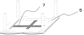
赤外線反射材は、成形時に隣り合う基材の境界部分の赤外線をカットすることで、該境界部分シートの加熱軟化(可塑化)を遅らせる。赤外線が照射されるシート面積を基材面積に適した大きさに区切ることにより、極度のドローダウンを防止することができる。(図3参照)
具体的には、熱可塑性樹脂シートと、該熱可塑性樹脂シート上に成形時に隣り合う基材の境界に位置するような赤外線反射材を設置した状態で赤外線を輻射すると、前記ヒーターと前記シートとの間に赤外線反射材がないシート部位(以下部位Aと称す)は赤外線が直接輻射されるために可塑化が生じるが、前記ヒーターと前記シートとの間に上に赤外線反射材があるシート部位(以下部位B)は赤外線が直接輻射されないので部位Aよりも熱が加わらず、可塑化が遅れる。即ち、部位Aが成形可能な状態に可塑化された状態であっても部位Bは可塑化が遅れているので、硬く、可塑化された部位Aを保持できるだけの強度を有している(図4参照)。その結果、シートのいずれの部位も極度のドローダウンは生じないので、シート中央とシート端とのシート展開率が異なることもなく、シート中央に位置する成形物とシート端に位置する成形物とで物性値や柄に差がでることもなく、歩留まり低下を抑えることができる。また部位Bは成形時に隣り合う基材の境界に位置するため、成形体に影響を与えることはない。
An infrared reflecting material delays heat softening (plasticization) of the boundary portion sheet by cutting infrared rays at the boundary portion between adjacent base materials during molding. An extreme drawdown can be prevented by dividing the sheet area irradiated with infrared rays into a size suitable for the substrate area. (See Figure 3)
Specifically, when the infrared ray is radiated in a state in which a thermoplastic resin sheet and an infrared reflecting material that is positioned at the boundary between adjacent substrates at the time of molding are installed on the thermoplastic resin sheet, the heater and the sheet The sheet part (hereinafter referred to as part A) having no infrared reflecting material between them is plasticized due to direct radiation of infrared rays, but the sheet part having an infrared reflecting material above the heater and the sheet. Since infrared rays are not directly radiated (hereinafter referred to as part B), heat is not applied as compared with part A, and plasticization is delayed. That is, even when the part A is plasticized to a moldable state, the part B is delayed in plasticization, and thus is hard and has a strength sufficient to hold the plasticized part A (see FIG. 4). As a result, extreme drawdown does not occur in any part of the sheet, so that the sheet development rate does not differ between the sheet center and the sheet edge, and the molded article positioned at the sheet center and the molded article positioned at the sheet edge Thus, there is no difference in physical property values and patterns, and yield reduction can be suppressed. Moreover, since the site | part B is located in the boundary of the adjacent base material at the time of shaping | molding, it does not affect a molded object.
赤外線反射材は、成形時に隣り合う基材の境界に位置するように設置することから、板状あるいはリボン状のある程度の幅を有する細長い形状を有するものであれば、硬さや厚み等には特に限定なく使用できる。真空成形機の大きさや使用するシートの大きさ、基材の数や取り数にもよるが、20mm以上の幅を有するものが、効果がより得られ好ましい。また長さとしては、例えばシートを枠状クランプで保持するのであれば、該クランプ枠の辺と同程度かそれ以上の長さ、部分クランプで保持するのであれば、各クランプ間の距離と同程度かそれ以上の長さであればよい。(図5、6参照) Since the infrared reflecting material is placed so as to be positioned at the boundary between adjacent substrates at the time of molding, particularly if it has an elongated shape having a certain width such as a plate shape or a ribbon shape, the hardness, thickness, etc. Can be used without limitation. Although it depends on the size of the vacuum forming machine, the size of the sheet to be used, the number of substrates and the number of substrates, one having a width of 20 mm or more is more preferable because of its effect. For example, if the sheet is held by a frame clamp, the length is about the same as or longer than the side of the clamp frame. If the sheet is held by a partial clamp, the length is the same as the distance between the clamps. It may be a length of about or longer. (See Figs. 5 and 6)
赤外線反射材の素材は、耐熱性を有し且つ赤外線を反射するものであれば特に限定はない。具体的にはアルミニウム、金、銀、銅、真鍮、チタン、クロム、ニッケル、ニッケルクロム、ステンレス等の金属やFe−Cr系複合酸化物、三酸化アンチモン、ジクロム酸アンチモン等を素材とする箔や板等が挙げられる。但し厚みのある金属板の場合には、熱伝導性の良いものは赤外線を反射する率よりも輻射熱を吸収してシートに余分な熱を加える恐れがあるので、あまり熱伝導性のよいものはさけたほうがよい。 The material of the infrared reflecting material is not particularly limited as long as it has heat resistance and reflects infrared rays. Specifically, foils made of metals such as aluminum, gold, silver, copper, brass, titanium, chromium, nickel, nickel chrome, stainless steel, Fe-Cr complex oxide, antimony trioxide, antimony dichromate, etc. A board etc. are mentioned. However, in the case of a thick metal plate, a material with good thermal conductivity absorbs radiant heat rather than the rate of reflecting infrared rays and may add extra heat to the sheet. You should avoid salmon.
真空成形機に熱可塑性樹脂シートを設置する際には、クランプを使用する。具体的には、シートの一部分を固定する方法やシートの全周囲を枠状クランプで固定する方法等が挙げられるが、熱可塑性樹脂シートの張力を適正化(均一化)することができるためシートの全周囲を枠状クランプでクランプする方法が好ましい。
前記工程(1)において、熱可塑性樹脂シートと、該熱可塑性樹脂シート上に成形時に隣り合う基材の境界に位置するような赤外線反射材を設置する場合には、前記赤外線反射材の端部を前記シートと共にクランプする方法や、端部を枠の内側に固定する方法等が挙げられる。
When installing a thermoplastic resin sheet in a vacuum forming machine, a clamp is used. Specific examples include a method of fixing a part of the sheet and a method of fixing the entire periphery of the sheet with a frame clamp. However, the tension of the thermoplastic resin sheet can be optimized (homogenized). A method of clamping the entire periphery of the substrate with a frame-like clamp is preferable.
In the step (1), when an infrared reflecting material located at the boundary between adjacent thermoplastic resin sheets and a base material adjacent to the thermoplastic resin sheet is formed on the thermoplastic resin sheet, an end portion of the infrared reflecting material And a method of clamping the end portion to the inside of the frame.
(赤外線反射インキで描いた線を有する熱可塑性樹脂シート)
本発明の製造方法における(1)赤外線反射インキで描いた線を有する熱可塑性樹脂シート(以下工程(1−2)と称す)において、赤外線反射インキとは、赤外線反射物質を含有するインキであり、照射された赤外線を反射する。
赤外線反射インキが含有する赤外線反射物質は、例えば、アルミニウム、金、銀、銅、真鍮、チタン、クロム、ニッケル、ニッケルクロム、ステンレス等の金属やFe−Cr系複合酸化物、三酸化アンチモン、ジクロム酸アンチモン等が挙げられる。具体的には、市販されている金属箔等を使用したメタリックインキ等を好適に使用することができる。また、金属箔等を使用したメタリックカラーを呈する油性ペン等も使用可能である。
(Thermoplastic resin sheet with lines drawn with infrared reflective ink)
In the thermoplastic resin sheet (hereinafter referred to as step (1-2)) having a line drawn with (1) infrared reflecting ink in the production method of the present invention, the infrared reflecting ink is an ink containing an infrared reflecting substance. , Reflects the irradiated infrared rays.
Infrared reflective materials contained in the infrared reflective ink include, for example, metals such as aluminum, gold, silver, copper, brass, titanium, chromium, nickel, nickel chromium, and stainless steel, Fe-Cr complex oxides, antimony trioxide, and dichrome. Antimony acid etc. are mentioned. Specifically, a metallic ink using a commercially available metal foil or the like can be suitably used. An oil-based pen or the like that exhibits a metallic color using a metal foil or the like can also be used.
前記熱可塑性樹脂シートに赤外線反射インキで絵柄を設ける方法は、手描きやコーティング、印刷等が挙げられるが、工業的には印刷が好ましい。方法については特に限定はなく、例えば、グラビア印刷、オフセット印刷、スクリーン印刷、インクジェット印刷、刷毛塗り、ロールコーティング、コンマコーティング、ロッドグラビアコーティング、マイクログラビアコーティングなどの方法が挙げられる。中でもグラビア印刷法が好ましい。 Examples of the method of providing a pattern with infrared reflection ink on the thermoplastic resin sheet include hand-drawing, coating, printing, and the like, but printing is preferred industrially. The method is not particularly limited, and examples thereof include gravure printing, offset printing, screen printing, ink jet printing, brush coating, roll coating, comma coating, rod gravure coating, and micro gravure coating. Of these, the gravure printing method is preferred.
前記赤外線反射インキで描いた線の太さや長さは、前記赤外線反射材と同様に、幅は20mm以上であり、また長さとしては、例えばシートを枠状クランプで保持するのであれば、該クランプ枠の辺と同程度かそれ以上の長さ、部分クランプで保持するのであれば、各クランプ間の距離と同程度かそれ以上の長さであればよい。(図4、5に準じる) The thickness and length of the line drawn with the infrared reflecting ink is 20 mm or more as in the infrared reflecting material, and the length is, for example, if the sheet is held by a frame-shaped clamp, If the length is equal to or longer than the side of the clamp frame and is held by a partial clamp, the length may be equal to or longer than the distance between the clamps. (According to FIGS. 4 and 5)
前記赤外線反射インキで描いた線を有する熱可塑性樹脂シートにおいて、赤外線反射インキで描いた線は、前述の工程(1−1)における赤外線反射材と同様の役割をする。即ち、赤外線反射インキで描いた線を有する熱可塑性樹脂シートを設置して(設置方法は前述と同様でよい)赤外線を輻射すると、赤外線反射インキで描いた線を有さないシート部位(以下部位A’と称す)は赤外線が直接輻射されるために可塑化が生じるが、赤外線反射インキで描いた線を有するシート部位(以下部位B’)は赤外線が直接輻射されないので部位A’よりも熱が加わらず、可塑化が遅れる。即ち、部位A’が成形可能な状態に可塑化された状態であっても部位B’は可塑化が遅れているので、硬く、可塑化された部位A’を保持できるだけの強度を有している。その結果、シートのいずれの部位も極度のドローダウンは生じないので、シート中央とシート端とのシート展開率が異なることもなく、シート中央に位置する成形物とシート端に位置する成形物とで物性値や柄に差がでることもなく、歩留まり低下を抑えることができる。また部位B’は成形時に隣り合う基材の境界に位置するため、成形体に影響を与えることはない。 In the thermoplastic resin sheet having a line drawn with the infrared reflecting ink, the line drawn with the infrared reflecting ink plays the same role as the infrared reflecting material in the step (1-1) described above. That is, when a thermoplastic resin sheet having a line drawn with infrared reflecting ink is installed (the installation method may be the same as described above), when infrared rays are radiated, a sheet part having no line drawn with infrared reflecting ink (the following part) A ′) is plasticized because infrared rays are directly radiated, but the sheet part (hereinafter referred to as part B ′) having a line drawn with infrared reflecting ink is not radiated directly, and therefore heat is more than part A ′. Will not be added and plasticization will be delayed. That is, even if the portion A ′ is plasticized into a moldable state, the portion B ′ is delayed in plasticization, so that it is hard and has a strength sufficient to hold the plasticized portion A ′. Yes. As a result, extreme drawdown does not occur in any part of the sheet, so that the sheet development rate does not differ between the sheet center and the sheet edge, and the molded article positioned at the sheet center and the molded article positioned at the sheet edge Thus, there is no difference in physical property values and patterns, and yield reduction can be suppressed. Further, since the part B ′ is located at the boundary between the adjacent base materials at the time of molding, it does not affect the molded body.
(その他の任意の層 接着層)
また、前記熱可塑性樹脂シートは、必要に応じて他の層を有していても良い。例えば真空成形同時加飾法においては、被着体との接着性を高める意味で、可塑性を示す樹脂層からなる接着剤や粘着剤等の接着層を有していてもよい。また、高い温度で可塑性を示す架橋型の樹脂層であっても真空成形できるようなら有していて構わない。このような観点から、耐摩擦性、耐摩傷性、耐候性、耐汚染性、耐水性、耐薬品性、耐熱性等の特性を付与する目的で、延展性を妨げない程度に一部架橋してなる表面保護層を有していても良い。架橋形態は特に限定はなく、イソシアネートと水酸基との熱硬化反応、エポキシ基と水酸基との熱硬化反応、(メタ)アクリロイル基のラジカル重合反応を利用したUVあるいは熱硬化反応、シラノール基や加水分解性シリル基の加水分解縮合反応等既存の反応を利用すればよいが、イソシアネートと水酸基との熱硬化反応が熱成形時にかかる熱を利用して架橋反応を促進することができるため好ましい。
(Other optional layers Adhesive layer)
Moreover, the said thermoplastic resin sheet may have another layer as needed. For example, in the vacuum molding simultaneous decorating method, an adhesive layer such as an adhesive or a pressure-sensitive adhesive made of a resin layer exhibiting plasticity may be included in order to enhance the adhesion to an adherend. Even a cross-linked resin layer exhibiting plasticity at a high temperature may be provided if it can be vacuum-formed. From this point of view, for the purpose of imparting characteristics such as friction resistance, scratch resistance, weather resistance, stain resistance, water resistance, chemical resistance, heat resistance, etc., it is partially crosslinked to such an extent that it does not interfere with spreadability. The surface protective layer may be provided. There are no particular limitations on the form of cross-linking, thermosetting reaction between isocyanate and hydroxyl group, thermosetting reaction between epoxy group and hydroxyl group, UV or thermosetting reaction using radical polymerization reaction of (meth) acryloyl group, silanol group or hydrolysis An existing reaction such as a hydrolytic condensation reaction of a functional silyl group may be used, but a thermosetting reaction between an isocyanate and a hydroxyl group is preferable because the crosslinking reaction can be promoted by using heat applied during thermoforming.
本発明の製造方法において、以下、(2)前記熱可塑性樹脂シートに赤外線照射する工程(以下工程(2)と称す)と
(3)前記熱可塑性樹脂シートを真空成形する工程(以下工程(3)と称す)
とは、通常の真空成形時における工程と同様である。
In the production method of the present invention, hereinafter, (2) a step of irradiating the thermoplastic resin sheet with infrared rays (hereinafter referred to as step (2)) and (3) a step of vacuum forming the thermoplastic resin sheet (hereinafter referred to as step (3) ))
Is the same as the process during normal vacuum forming.
前記工程(2)で使用する赤外線輻射ヒーターは、赤色から近赤外、赤外レーザー光の波長域であれば特に限定はなく使用できる。多くの場合、真空成形法、圧空真空成形法等に用いる既存の熱成形機には、加熱手段として赤外線照射装置が設置あるいは外付けできるようになっているので、これを利用することが好ましい。具体的には、遠赤外から近赤外の領域に強い波長ピークをもつハロゲンヒーター、短波長ヒーター、カーボンヒーター、中赤外線ヒーター、遠赤外線ヒーター等が挙げられる。 The infrared radiation heater used in the step (2) is not particularly limited as long as it is in a wavelength range from red to near infrared and infrared laser light. In many cases, an existing thermoforming machine used for a vacuum forming method, a compressed air vacuum forming method or the like can be installed or externally provided with an infrared irradiation device as a heating means. Specific examples include halogen heaters having a strong wavelength peak in the far infrared to near infrared region, short wavelength heaters, carbon heaters, mid-infrared heaters, and far-infrared heaters.
その後、工程(3)で真空成形する。真空成形方法は、使用する真空成形機に準じた方法で行う。 Thereafter, vacuum forming is performed in step (3). The vacuum forming method is performed by a method according to the vacuum forming machine to be used.
(基材)
金型や被着体等の基材の形状は、特に限定はなく、所望の形状で真空成形が可能である。だが、あまり大きな基材よりは、小さな基材を使用する多数個取りの真空成形に本発明の方法は適している。
(Base material)
The shape of the base material such as a mold or an adherend is not particularly limited, and vacuum forming can be performed in a desired shape. However, the method of the present invention is suitable for multi-cavity vacuum forming using a small substrate rather than a very large substrate.
真空成形後はトリミングすることで、各々の成形体を得ることができる。トリミング加工方法についても特に限定はなく、はさみやカッター等でカットする方法、ダイカット法、レーザーカット法、ウォータージェット法、抜き刃プレス法により加工することができる。 Each molded body can be obtained by trimming after vacuum forming. The trimming method is not particularly limited, and the trimming method can be processed by a method of cutting with scissors or a cutter, a die cutting method, a laser cutting method, a water jet method, or a punching blade press method.
以下、本発明を実施例により説明する。特に断わりのない限り「部」、「%」は質量基準である。 Hereinafter, the present invention will be described with reference to examples. Unless otherwise specified, “part” and “%” are based on mass.
(熱可塑性樹脂シート)
熱可塑性樹脂シートとしては、以下のシートを使用した。
・東洋紡績株式会社製PETシート「ソフトシャインX1130」(膜厚125μm)
・東洋紡績株式会社製PETシート「ソフトシャインX1130」(膜厚188μm)
・サンビック株式会社製PPシート「PP39LMS2−30R黒」(膜厚300μm)
(Thermoplastic resin sheet)
The following sheets were used as the thermoplastic resin sheet.
・ PET sheet "Soft Shine X1130" manufactured by Toyobo Co., Ltd. (film thickness 125μm)
-PET sheet "Soft Shine X1130" manufactured by Toyobo Co., Ltd. (film thickness: 188 μm)
-PP sheet "PP39LMS2-30R black" manufactured by Sanvic Co., Ltd. (film thickness 300 μm)
(赤外線反射材)
赤外線反射材は以下の素材を使用した。
・アルミニウム箔(膜厚20μm)
(Infrared reflector)
The following materials were used for the infrared reflecting material.
・ Aluminum foil (film thickness 20μm)
(赤外線反射インキ:ペン)
赤外線反射インキ(ペン)は以下のインキを使用した。
・三菱鉛筆株式会社製「ペイントマーカー銀色」 赤外線反射インキとして使用。
・三菱鉛筆株式会社製「ペイントマーカー青色」 色インキとして使用。
(Infrared reflective ink: pen)
The following ink was used as the infrared reflection ink (pen).
・ Mitsubishi Pencil Co., Ltd. “paint marker silver” Used as infrared reflective ink.
・ Mitsubishi Pencil Co., Ltd. “Paint Marker Blue” Used as color ink.
(赤外線反射インキ:光輝性インキ(A))
赤外線反射インキ「光輝性インキ(A)」は以下を混合、使用した。
・Ciba製 「METASHEEEN 71−0010」37部
・DIC株式会社製「XS−756 BKN メジュームB」63部
(Infrared reflective ink: glitter ink (A))
The infrared reflection ink “Brightness Ink (A)” was mixed and used as follows.
-37 parts of Ciba "METASHEEEN 71-0010"-63 parts of "XS-756 BKN Medium B" made by DIC Corporation
(赤外線反射インキ印刷方法)
前記熱可塑性樹脂シートに、前記インキを使用して、手描きにて、該熱可塑性樹脂シート上に成形時に隣り合う基材の境界に位置するような直線を描いた。
(Infrared reflective ink printing method)
On the thermoplastic resin sheet, using the ink, a straight line was drawn by hand-drawing on the thermoplastic resin sheet so as to be positioned at the boundary between adjacent substrates during molding.
(実施例1) 成形時に隣り合う基材の境界に位置するように赤外線反射インキで描いた線を有する熱可塑性樹脂シートを設置した例
布施真空株式会社製真空成形機「NGF−0709型(赤外線ヒーターはシート上方から照射する)」を使用し、真空成形を行った。
赤外線反射インキ「ペイントマーカー銀色」を使用し、熱可塑性樹脂シートである東洋紡績株式会社製PETシート「ソフトシャインX1130」(膜厚125μm 縦700mm×横950mmの長方形シート)のシート面に、長方形の長辺を均等に2分するように、短辺に平行な幅20mmの線を描いた。
前記線を描いた面が赤外線ヒーター側となるように、前記熱可塑性樹脂シートの周囲を完全にクランプして設置した。
線で区切られた前記シート(部位A’)の下に位置する様に可動テーブルに基材を設置し、真空成形機の上下ボックスを閉じ、ボックス内をほぼ完全真空状態にした後、赤外線ヒーターとしてヘリウス社製中赤外線ヒーターを使用し前記熱可塑性樹脂シートを間接加熱し、前記熱可塑性樹脂シートの部位Aの表面温度が放射温度計測定値で194℃になるまで上昇させた。(赤外線ヒーターと熱可塑性樹脂シートとの距離は250mm程度である)
このとき、赤外線反射インキが描かれた部位B’は加熱軟化によるドローダウンは生じずに、シート部位A’はドローダウンの深さが10mm以内に抑えられていた。
その後基材を乗せた可動テーブルを上昇させ、上ボックス中に0.2MPaの圧空を吹き込み、前記熱可塑性樹脂シートを基材に貼り付けて一体成形させ、真空成形を行った。
その後、トリミングを行い、熱可塑性樹脂シートが表面に加飾された2個の真空成形体を得た。得られた2つの真空成形体のシート膜厚の差異や破れ、皺等はなく、均一な品質の真空成形体が得られた。
(Example 1) Example in which a thermoplastic resin sheet having a line drawn with infrared reflecting ink is placed so as to be positioned at the boundary between adjacent substrates at the time of molding Vacuum forming machine “NGF-0709 type (infrared ray) manufactured by Fuse Vacuum Co., Ltd. The heater was irradiated from above the sheet) ”and vacuum forming was performed.
Infrared reflective ink “paint marker silver” is used, and the sheet surface of PET sheet “Soft Shine X1130” (film thickness 125 μm length 700 mm × width 950 mm rectangular sheet) manufactured by Toyobo Co., Ltd., which is a thermoplastic resin sheet, is rectangular. A line having a width of 20 mm parallel to the short side was drawn so that the long side was equally divided into two.
The periphery of the thermoplastic resin sheet was completely clamped and installed so that the surface on which the line was drawn was on the infrared heater side.
Place the base material on the movable table so that it is located under the sheet (part A ′) separated by a line, close the upper and lower boxes of the vacuum forming machine, and make the inside of the box almost completely vacuumed, then the infrared heater As described above, the thermoplastic resin sheet was indirectly heated using a mid-infrared heater manufactured by Helius Co., Ltd., and the surface temperature of the portion A of the thermoplastic resin sheet was increased to 194 ° C. as measured by a radiation thermometer. (The distance between the infrared heater and the thermoplastic resin sheet is about 250 mm)
At this time, the draw-down due to heat softening did not occur in the portion B ′ where the infrared reflective ink was drawn, and the depth of the draw-down in the sheet portion A ′ was suppressed within 10 mm.
Thereafter, the movable table on which the substrate was placed was raised, 0.2 MPa of compressed air was blown into the upper box, the thermoplastic resin sheet was attached to the substrate and integrally molded, and vacuum forming was performed.
Thereafter, trimming was performed to obtain two vacuum molded bodies with a thermoplastic resin sheet decorated on the surface. There was no difference in the film thickness of the two vacuum formed bodies, no tears, no wrinkles, etc., and a vacuum formed body of uniform quality was obtained.
(実施例2)成形時に隣り合う基材の境界に位置するように赤外線反射インキで描いた線を有する熱可塑性樹脂シートを設置した例
実施例1において、熱可塑性樹脂シートの片面(赤外線反射インキを描いた面の反対面)に印刷層を有しているシートを使用した以外は実施例1と同様にして、真空成形を行い、2個の真空成形体を得た。
真空成形時、赤外線反射インキが描かれた部位B’は加熱軟化によるドローダウンは生じずに、シート部位A’はドローダウンの深さが10mm以内に抑えられていた。得られた2つの真空成形体のシート膜厚の差異や破れ、皺等はなく、均一な品質の真空成形体が得られた。
(Example 2) Example in which a thermoplastic resin sheet having a line drawn with infrared reflecting ink is placed so as to be positioned at the boundary between adjacent substrates at the time of molding In Example 1, one side of the thermoplastic resin sheet (infrared reflecting ink) The vacuum forming was performed in the same manner as in Example 1 except that a sheet having a printed layer was used on the surface opposite to the surface on which two were formed, and two vacuum formed bodies were obtained.
At the time of vacuum forming, the draw-down due to heat softening did not occur in the portion B ′ where the infrared reflecting ink was drawn, and the depth of the draw-down of the sheet portion A ′ was suppressed to within 10 mm. There was no difference in the film thickness of the two vacuum formed bodies, no tears, no wrinkles, etc., and a vacuum formed body of uniform quality was obtained.
(実施例3)成形時に隣り合う基材の境界に位置するように赤外線反射インキで描いた線を有する熱可塑性樹脂シートを設置した例
実施例1において、熱可塑性樹脂シートとして東洋紡績株式会社製PETシート「ソフトシャインX1130」(膜厚188μm)を使用した以外は実施例1と同様にして、真空成形を行い、2個の真空成形体を得た。
真空成形時、赤外線反射インキが描かれた部位B’は加熱軟化によるドローダウンは生じずに、シート部位A’はドローダウンの深さが10mm以内に抑えられていた。得られた2つの真空成形体のシート膜厚の差異や破れ、皺等はなく、均一な品質の真空成形体が得られた。
(Example 3) Example in which a thermoplastic resin sheet having a line drawn with infrared reflecting ink is placed so as to be positioned at the boundary between adjacent substrates at the time of molding In Example 1, as a thermoplastic resin sheet, manufactured by Toyobo Co., Ltd. Except for using the PET sheet “Soft Shine X1130” (film thickness: 188 μm), vacuum forming was performed in the same manner as in Example 1 to obtain two vacuum formed bodies.
At the time of vacuum forming, the draw-down due to heat softening did not occur in the portion B ′ where the infrared reflecting ink was drawn, and the depth of the draw-down of the sheet portion A ′ was suppressed to within 10 mm. There was no difference in the film thickness of the two vacuum formed bodies, no tears, no wrinkles, etc., and a vacuum formed body of uniform quality was obtained.
(実施例4)成形時に隣り合う基材の境界に位置するように赤外線反射インキで描いた線を有する熱可塑性樹脂シートを設置した例
実施例1において、熱可塑性樹脂シートとしてサンビック株式会社製PPシート「PP39LMS2−30R黒」(膜厚300μm)を使用し、成形温度を145℃にした以外は実施例1と同様にして、真空成形を行い、2個の真空成形体を得た。
真空成形時、赤外線反射インキが描かれた部位B’は加熱軟化によるドローダウンは生じずに、シート部位A’はドローダウンの深さが10mm以内に抑えられていた。得られた2つの真空成形体のシート膜厚の差異や破れ、皺等はなく、均一な品質の真空成形体が得られた。
(Example 4) Example in which a thermoplastic resin sheet having a line drawn with infrared reflecting ink is placed so as to be positioned at the boundary between adjacent substrates at the time of molding In Example 1, PP manufactured by Sanbic Co., Ltd. is used as the thermoplastic resin sheet. A sheet “PP39LMS2-30R black” (film thickness 300 μm) was used, and vacuum forming was performed in the same manner as in Example 1 except that the forming temperature was 145 ° C., and two vacuum formed bodies were obtained.
At the time of vacuum forming, the draw-down due to heat softening did not occur in the portion B ′ where the infrared reflecting ink was drawn, and the depth of the draw-down of the sheet portion A ′ was suppressed to within 10 mm. There was no difference in the film thickness of the two vacuum formed bodies, no tears, no wrinkles, etc., and a vacuum formed body of uniform quality was obtained.
(実施例5)成形時に隣り合う基材の境界に位置するように赤外線反射インキで描いた線を有する熱可塑性樹脂シートを設置した例
実施例1において、赤外線反射インキ「ペイントマーカー銀色」の代わりに光輝性インキ(A)を刷毛を使用して幅20mmの線を描いた以外は実施例1と同様にして、真空成形を行い、2個の真空成形体を得た。
真空成形時、赤外線反射インキが描かれた部位B’は加熱軟化によるドローダウンは生じずに、シート部位A’はドローダウンの深さが10mm以内に抑えられていた。得られた2つの真空成形体のシート膜厚の差異や破れ、皺等はなく、均一な品質の真空成形体が得られた。
(Example 5) Example in which a thermoplastic resin sheet having a line drawn with infrared reflecting ink is placed so as to be positioned at the boundary between adjacent substrates at the time of molding In Example 1, instead of infrared reflecting ink “paint marker silver” A vacuum forming was performed in the same manner as in Example 1 except that a line having a width of 20 mm was drawn using a brush with the glitter ink (A) to obtain two vacuum formed bodies.
At the time of vacuum forming, the draw-down due to heat softening did not occur in the portion B ′ where the infrared reflecting ink was drawn, and the depth of the draw-down of the sheet portion A ′ was suppressed to within 10 mm. There was no difference in the film thickness of the two vacuum formed bodies, no tears, no wrinkles, etc., and a vacuum formed body of uniform quality was obtained.
(実施例6)成形時に隣り合う基材の境界に位置するように赤外線反射インキで描いた線を有する熱可塑性樹脂シートを設置した例
三和興業株式会社製真空成形機「PLAVAC TV−33(赤外線メインヒーターはシート下方から照射する)」を使用し、真空成形を行った。
赤外線反射インキ「ペイントマーカー銀色」を使用し、熱可塑性樹脂シートである東洋紡績株式会社製PETシート「ソフトシャインX1130」(膜厚125μm 縦320mm×横500mmの長方形シート)のシート面に、長方形の長辺を均等に2分するように、短辺に平行な幅20mmの線を描いた。
前記線を描いた面が赤外線メインヒーター側となるように、前記熱可塑性樹脂シートの周囲を完全にクランプして設置した。
線で区切られた前記シート(部位A’)の下に位置する様に可動テーブルに基材を設置し、赤外線ヒーターとして遠赤外線ヒーターを使用し前記熱可塑性樹脂シートを間接加熱し、前記熱可塑性樹脂シートの部位Aを加熱した。(赤外線ヒーターと熱可塑性樹脂シートとの距離は150mm程度である)
このとき、赤外線反射インキが描かれた部位B’は加熱軟化によるドローダウンは生じずに、シート部位A’はドローダウンの深さが10mm以内に抑えられていた。
その後基材を乗せた可動テーブルを上昇させて前記熱可塑性樹脂シートの真空成形を行った。
その後、トリミングを行い、熱可塑性樹脂シートの2個の真空成形体を得た。得られた2つの真空成形体のシート膜厚の差異や破れ、皺等はなく、均一な品質の真空成形体が得られた。
(Example 6) An example in which a thermoplastic resin sheet having a line drawn with infrared reflecting ink is placed so as to be positioned at the boundary between adjacent substrates at the time of molding Sanwa Kogyo Co., Ltd. vacuum forming machine "PLAVAC TV-33 ( The infrared main heater is irradiated from the lower side of the sheet) ”and vacuum forming was performed.
Infrared reflective ink “paint marker silver” is used, and the sheet surface of PET sheet “Soft Shine X1130” (film thickness 125 μm length 320 mm × width 500 mm rectangular sheet) manufactured by Toyobo Co., Ltd. is a thermoplastic resin sheet. A line having a width of 20 mm parallel to the short side was drawn so that the long side was equally divided into two.
The thermoplastic resin sheet was completely clamped and installed so that the surface on which the line was drawn was on the infrared main heater side.
A base is placed on the movable table so as to be positioned under the sheet (part A ′) separated by a line, and the thermoplastic resin sheet is indirectly heated using a far infrared heater as an infrared heater, and the thermoplastic The part A of the resin sheet was heated. (The distance between the infrared heater and the thermoplastic resin sheet is about 150 mm)
At this time, the draw-down due to heat softening did not occur in the portion B ′ where the infrared reflective ink was drawn, and the depth of the draw-down in the sheet portion A ′ was suppressed within 10 mm.
Thereafter, the movable table on which the substrate was placed was raised, and the thermoplastic resin sheet was vacuum-formed.
Thereafter, trimming was performed to obtain two vacuum molded bodies of thermoplastic resin sheets. There was no difference in the film thickness of the two vacuum formed bodies, no tears, no wrinkles, etc., and a vacuum formed body of uniform quality was obtained.
(実施例7)熱可塑性樹脂シートと、該熱可塑性樹脂シート上に成形時に隣り合う基材の境界に位置するような赤外線反射材を設置した例
布施真空株式会社製真空成形機「NGF−0709型」を使用し、真空成形を行った。
熱可塑性樹脂シートである東洋紡績株式会社製PETシート「ソフトシャインX1130」(膜厚125μm 縦700mm×横950mmの長方形シート)のシートと、該シートの長方形の長辺を均等に2分するように、短辺に平行となるように該シート上に設置したアルミニウム箔(膜厚20μm、幅20mm)とを、前記アルミニウム箔の設置面が赤外線ヒーター側となるように、前記アルミニウム箔の端がクランプされるように、前記熱可塑性樹脂シートの周囲を完全にクランプして設置した。
アルミニウム箔で区切られた前記シート(部位A)の下に位置する様に可動テーブルに基材を設置し、真空成形機の上下ボックスを閉じ、ボックス内をほぼ完全真空状態にした後、赤外線ヒーターとしてヘリウス社製中赤外線ヒーターを使用し前記熱可塑性樹脂シートを間接加熱し、前記熱可塑性樹脂シートの部位Aの表面温度が放射温度計測定値で194℃になるまで上昇させた。(赤外線ヒーターと熱可塑性樹脂シートとの距離は250mm程度である)
このとき、赤外線反射インキが描かれた部位Bは加熱軟化によるドローダウンは生じずに、シート部位Aはドローダウンの深さが10mm以内に抑えられていた。
その後基材を乗せた可動テーブルを上昇させ、上ボックス中に0.2MPaの圧空を吹き込み、前記熱可塑性樹脂シートを基材に貼り付けて一体成形させ、真空成形を行った。
その後、トリミングを行い、熱可塑性樹脂シートが表面に加飾された2個の真空成形体を得た。得られた2つの真空成形体のシート膜厚の差異や破れ、皺等はなく、均一な品質の真空成形体が得られた。
(Example 7) An example in which a thermoplastic resin sheet and an infrared reflecting material positioned on the boundary between adjacent substrates at the time of molding are installed on the thermoplastic resin sheet. Vacuum forming machine “NGF-0709” manufactured by Fuse Vacuum Co., Ltd. The mold was used for vacuum forming.
A sheet of Toyobo Co., Ltd. PET sheet “Soft Shine X1130” (thickness 125 μm length 700 mm × width 950 mm rectangular sheet) which is a thermoplastic resin sheet, and the long side of the rectangle of the sheet are equally divided into two. The end of the aluminum foil is clamped so that the aluminum foil (film thickness 20 μm, width 20 mm) placed on the sheet so as to be parallel to the short side is the infrared heater side. As described above, the periphery of the thermoplastic resin sheet was completely clamped and installed.
Place the base material on the movable table so that it is located under the sheet (part A) separated by the aluminum foil, close the upper and lower boxes of the vacuum forming machine, make the inside of the box almost completely vacuumed, and then the infrared heater As described above, the thermoplastic resin sheet was indirectly heated using a mid-infrared heater manufactured by Helius Co., Ltd., and the surface temperature of the portion A of the thermoplastic resin sheet was increased to 194 ° C. as measured by a radiation thermometer. (The distance between the infrared heater and the thermoplastic resin sheet is about 250 mm)
At this time, the draw-down due to heat softening did not occur in the portion B where the infrared reflective ink was drawn, and the depth of the draw-down in the sheet portion A was suppressed to within 10 mm.
Thereafter, the movable table on which the substrate was placed was raised, 0.2 MPa of compressed air was blown into the upper box, the thermoplastic resin sheet was attached to the substrate and integrally molded, and vacuum forming was performed.
Thereafter, trimming was performed to obtain two vacuum molded bodies with a thermoplastic resin sheet decorated on the surface. There was no difference in the film thickness of the two vacuum formed bodies, no tears, no wrinkles, etc., and a vacuum formed body of uniform quality was obtained.
(比較例1)
実施例1において、赤外線反射インキ「ペイントマーカー銀色」の代わりに色インキ「ペイントマーカー青色」を使用した以外は実施例1と同様にして、真空成形を行い、2個の真空成形体を得た。
真空成形時、色インキが描かれた部位B’は、シート部位A’と全く同様に加熱軟化し、一体となってドローダウンした。それによりドローダウンの深さは50mmほどになった。その結果、賦形時にシートの過剰な伸びが元に戻らず、成形体に皺が残った。
(Comparative Example 1)
In Example 1, vacuum forming was performed in the same manner as in Example 1 except that the color ink “paint marker blue” was used instead of the infrared reflective ink “paint marker silver”, and two vacuum formed bodies were obtained. .
At the time of vacuum forming, the part B ′ on which the color ink was drawn was softened by heating in the same manner as the sheet part A ′, and was integrally drawn down. Thereby, the depth of the drawdown became about 50 mm. As a result, excessive elongation of the sheet did not return to the original during shaping, and wrinkles remained in the molded body.
1:熱可塑性樹脂シート
2:赤外線輻射ヒーター
3:赤外線
4:被着体
5:クランプ
6:真空成形機ボックス
7:赤外線反射材
8:部位A、A’
9:部位B、B’
1: Thermoplastic resin sheet 2: Infrared radiation heater 3: Infrared ray 4: Substrate 5: Clamp 6: Vacuum molding machine box 7: Infrared reflector 8: Sites A and A ′
9: Sites B and B ′
Claims (3)
(1)熱可塑性樹脂シートと、該熱可塑性樹脂シート上に成形時に隣り合う基材の境界に位置するような赤外線反射材を設置する工程、又は、
成形時に隣り合う基材の境界に位置するように赤外線反射インキで描いた線を有する熱可塑性樹脂シートを設置する工程と、
(2)前記熱可塑性樹脂シートに赤外線照射する工程と
(3)前記熱可塑性樹脂シートを真空成形する工程、
とをこの順に有することを特徴とする、真空成形体の製造方法。 A method of manufacturing a vacuum formed body in which at least two moldings are performed simultaneously,
(1) A step of installing a thermoplastic resin sheet and an infrared reflecting material located on a boundary between adjacent substrates at the time of molding on the thermoplastic resin sheet, or
A step of installing a thermoplastic resin sheet having a line drawn with an infrared reflective ink so as to be positioned at the boundary between adjacent substrates at the time of molding;
(2) a step of irradiating the thermoplastic resin sheet with infrared rays; and (3) a step of vacuum forming the thermoplastic resin sheet.
And in this order, a method for producing a vacuum formed body.
(1)熱可塑性樹脂シートと、該熱可塑性樹脂シート上に成形時に隣り合う基材の境界に位置するような赤外線反射材を設置する工程、又は、
成形時に隣り合う基材の境界に位置するように赤外線反射インキで描いた線を有する熱可塑性樹脂シートを設置する工程と、
(2)前記熱可塑性樹脂シートに赤外線照射する工程と
(3)前記熱可塑性樹脂シートを真空成形する工程、
とをこの順に有することを特徴とする、ドローダウン防止方法。 A method of preventing drawdown during vacuum forming in which at least two moldings are performed simultaneously,
(1) A step of installing a thermoplastic resin sheet and an infrared reflecting material located on a boundary between adjacent substrates at the time of molding on the thermoplastic resin sheet, or
A step of installing a thermoplastic resin sheet having a line drawn with an infrared reflective ink so as to be positioned at the boundary between adjacent substrates at the time of molding;
(2) a step of irradiating the thermoplastic resin sheet with infrared rays; and (3) a step of vacuum forming the thermoplastic resin sheet.
A method for preventing a drawdown, comprising:
Priority Applications (1)
| Application Number | Priority Date | Filing Date | Title |
|---|---|---|---|
| JP2010057500A JP2011189620A (en) | 2010-03-15 | 2010-03-15 | Method of manufacturing vacuum formed product, drawdown preventing method, and sheet for vacuum forming |
Applications Claiming Priority (1)
| Application Number | Priority Date | Filing Date | Title |
|---|---|---|---|
| JP2010057500A JP2011189620A (en) | 2010-03-15 | 2010-03-15 | Method of manufacturing vacuum formed product, drawdown preventing method, and sheet for vacuum forming |
Publications (1)
| Publication Number | Publication Date |
|---|---|
| JP2011189620A true JP2011189620A (en) | 2011-09-29 |
Family
ID=44795042
Family Applications (1)
| Application Number | Title | Priority Date | Filing Date |
|---|---|---|---|
| JP2010057500A Pending JP2011189620A (en) | 2010-03-15 | 2010-03-15 | Method of manufacturing vacuum formed product, drawdown preventing method, and sheet for vacuum forming |
Country Status (1)
| Country | Link |
|---|---|
| JP (1) | JP2011189620A (en) |
Cited By (1)
| Publication number | Priority date | Publication date | Assignee | Title |
|---|---|---|---|---|
| CN108454072A (en) * | 2018-01-08 | 2018-08-28 | 上海古汉汽车饰件模具有限公司 | A kind of fascia vacuum adsorption molding integration mold |
Citations (1)
| Publication number | Priority date | Publication date | Assignee | Title |
|---|---|---|---|---|
| JPS4945164A (en) * | 1972-09-06 | 1974-04-30 |
-
2010
- 2010-03-15 JP JP2010057500A patent/JP2011189620A/en active Pending
Patent Citations (1)
| Publication number | Priority date | Publication date | Assignee | Title |
|---|---|---|---|---|
| JPS4945164A (en) * | 1972-09-06 | 1974-04-30 |
Cited By (1)
| Publication number | Priority date | Publication date | Assignee | Title |
|---|---|---|---|---|
| CN108454072A (en) * | 2018-01-08 | 2018-08-28 | 上海古汉汽车饰件模具有限公司 | A kind of fascia vacuum adsorption molding integration mold |
Similar Documents
| Publication | Publication Date | Title |
|---|---|---|
| JP4609605B2 (en) | Method for producing decorative molded body | |
| JP5223221B2 (en) | Transfer decorative sheet, method for producing decorative molded product, and decorative molded product | |
| JP5694641B2 (en) | Lapping solid molded body and method for producing the same | |
| JP4811541B2 (en) | Manufacturing method of injection molded body | |
| KR20060120155A (en) | Decorating sheet, decorated resin molded article and method for production thereof | |
| JP6128854B2 (en) | Manufacturing method of pneumatic molded products | |
| KR101627431B1 (en) | A Light Guiding Decorative Composite Sheet and Components Made Thereof | |
| CN111566150B (en) | Film for holding metal layer, metallic decorative sheet intermediate, metallic decorative sheet, and extrusion-laminated body | |
| JP2021530382A (en) | Compatibility shielding film | |
| JP7074436B2 (en) | Decorative sheet, structure including decorative sheet and method of manufacturing decorative sheet | |
| JP4919137B2 (en) | Molding sheet and manufacturing method thereof | |
| JP2011189620A (en) | Method of manufacturing vacuum formed product, drawdown preventing method, and sheet for vacuum forming | |
| KR102196604B1 (en) | Film, film molding method, mold, molding comprising film, and molding method therefor | |
| CN111684034B (en) | Thermally stretchable decorative film for light projection and article bonded therewith | |
| JP2009262521A (en) | Transfer foil | |
| JP5641307B2 (en) | Method for producing vacuum formed body having uneven pattern and resin container | |
| CN111315572A (en) | Light-transmitting decorative film, molded article including light-transmitting decorative film, method for producing the molded article, and illuminated display device | |
| JP7048399B2 (en) | A heat-stretchable decorative film for three-dimensional coating molding, an article to which it is attached, and a method for manufacturing these. | |
| JP5531686B2 (en) | Decorative sheet for thermoforming and method for producing decorative molded body | |
| JP2007070518A (en) | Adhesive agent for molded sheet and molded sheet for decorating molded article | |
| US20060267256A1 (en) | Systems and methods for molding a thermoplastic | |
| JP5641306B2 (en) | Method for producing decorative molded body | |
| JP5641313B2 (en) | Laminated sheet for decorating back surface, back surface decorating body, and manufacturing method of back surface decorating body | |
| JP7000653B2 (en) | Decorative film, transfer sheet, decorative molded product and its manufacturing method | |
| JP2012000781A (en) | Method for manufacturing decorative sheet with unevenness on surface |
Legal Events
| Date | Code | Title | Description |
|---|---|---|---|
| A621 | Written request for application examination |
Free format text: JAPANESE INTERMEDIATE CODE: A621 Effective date: 20130111 |
|
| A977 | Report on retrieval |
Free format text: JAPANESE INTERMEDIATE CODE: A971007 Effective date: 20140129 |
|
| A131 | Notification of reasons for refusal |
Free format text: JAPANESE INTERMEDIATE CODE: A131 Effective date: 20140204 |
|
| A02 | Decision of refusal |
Free format text: JAPANESE INTERMEDIATE CODE: A02 Effective date: 20140624 |