JP2011189534A - Tape printer, method for controlling the same and program - Google Patents
Tape printer, method for controlling the same and program Download PDFInfo
- Publication number
- JP2011189534A JP2011189534A JP2010055461A JP2010055461A JP2011189534A JP 2011189534 A JP2011189534 A JP 2011189534A JP 2010055461 A JP2010055461 A JP 2010055461A JP 2010055461 A JP2010055461 A JP 2010055461A JP 2011189534 A JP2011189534 A JP 2011189534A
- Authority
- JP
- Japan
- Prior art keywords
- tape
- enlarged
- margin
- printing
- tape width
- Prior art date
- Legal status (The legal status is an assumption and is not a legal conclusion. Google has not performed a legal analysis and makes no representation as to the accuracy of the status listed.)
- Withdrawn
Links
Images


Classifications
-
- B—PERFORMING OPERATIONS; TRANSPORTING
- B41—PRINTING; LINING MACHINES; TYPEWRITERS; STAMPS
- B41J—TYPEWRITERS; SELECTIVE PRINTING MECHANISMS, i.e. MECHANISMS PRINTING OTHERWISE THAN FROM A FORME; CORRECTION OF TYPOGRAPHICAL ERRORS
- B41J3/00—Typewriters or selective printing or marking mechanisms characterised by the purpose for which they are constructed
- B41J3/407—Typewriters or selective printing or marking mechanisms characterised by the purpose for which they are constructed for marking on special material
- B41J3/4075—Tape printers; Label printers
-
- B—PERFORMING OPERATIONS; TRANSPORTING
- B41—PRINTING; LINING MACHINES; TYPEWRITERS; STAMPS
- B41J—TYPEWRITERS; SELECTIVE PRINTING MECHANISMS, i.e. MECHANISMS PRINTING OTHERWISE THAN FROM A FORME; CORRECTION OF TYPOGRAPHICAL ERRORS
- B41J21/00—Column, tabular or like printing arrangements; Means for centralising short lines
-
- B—PERFORMING OPERATIONS; TRANSPORTING
- B41—PRINTING; LINING MACHINES; TYPEWRITERS; STAMPS
- B41J—TYPEWRITERS; SELECTIVE PRINTING MECHANISMS, i.e. MECHANISMS PRINTING OTHERWISE THAN FROM A FORME; CORRECTION OF TYPOGRAPHICAL ERRORS
- B41J3/00—Typewriters or selective printing or marking mechanisms characterised by the purpose for which they are constructed
- B41J3/36—Typewriters or selective printing or marking mechanisms characterised by the purpose for which they are constructed for portability, i.e. hand-held printers or laptop printers
-
- G—PHYSICS
- G06—COMPUTING; CALCULATING OR COUNTING
- G06K—GRAPHICAL DATA READING; PRESENTATION OF DATA; RECORD CARRIERS; HANDLING RECORD CARRIERS
- G06K15/00—Arrangements for producing a permanent visual presentation of the output data, e.g. computer output printers
- G06K15/02—Arrangements for producing a permanent visual presentation of the output data, e.g. computer output printers using printers
- G06K15/021—Adaptations for printing on specific media
- G06K15/022—Adaptations for printing on specific media for printing on continuous media, e.g. tapes
Abstract
Description
本発明は、テープ印刷装置、テープ印刷装置の制御方法、およびプログラムに関する。 The present invention relates to a tape printer, a control method for the tape printer, and a program.
従来、テープ幅より大きな印刷画像の一部が印刷された各テープ部分(テープ片)を、複数貼り合わせることによって印刷画像を形成する、いわゆる「拡大印刷機能」を備えたテープ印刷装置が知られている(例えば、特許文献1)。この拡大印刷機能を備えたテープ印刷装置では、印刷画像の一部がそれぞれ印刷された同じ長さの印刷済みテープ部分を、テープ幅方向に平設することによって印刷画像、即ち拡大印刷画像を形成することができる。 2. Description of the Related Art Conventionally, a tape printer having a so-called “enlarged printing function” that forms a printed image by bonding a plurality of tape portions (tape pieces) on which a part of a printed image larger than the tape width is printed is known. (For example, Patent Document 1). In a tape printer equipped with this enlarged printing function, a printed image, that is, an enlarged printed image, is formed by laying the same length of a printed tape portion on which a part of the printed image is printed in the tape width direction. can do.
さらに、拡大印刷機能において、テープ長方向における印刷画像が存在しない前端部分および後端部分である非印刷画像領域を削除する画像データ生成装置(テープ印刷装置)が開示されている(特許文献2)。このような画像データ生成装置によれば、拡大印刷において、テープ長方向のテープの使用量を削減することが可能となる。 Furthermore, an image data generation device (tape printing device) that deletes a non-printing image area that is a front end portion and a rear end portion where no print image exists in the tape length direction in the enlargement printing function is disclosed (Patent Document 2). . According to such an image data generation device, it is possible to reduce the amount of tape used in the tape length direction in enlarged printing.
しかしながら、拡大印刷機能においては、テープ幅方向においても印刷画像が存在しない上端部分(上側余白)および下端部分(下側余白)である非印刷画像領域が生じる。この非印刷画像領域がテープ幅以上となる場合には、非印刷画像領域に相当するテープ部分は、テープ印刷装置から出力されても使用されずに無駄となってしまう場合があった。 However, in the enlarged printing function, a non-printing image area is generated which is an upper end portion (upper margin) and a lower end portion (lower margin) where no print image exists even in the tape width direction. When the non-print image area is equal to or larger than the tape width, the tape portion corresponding to the non-print image area may be wasted without being used even if it is output from the tape printer.
本発明は、上述の課題の少なくとも一部を解決するためになされたものであり、以下の形態または適用例として実現することが可能である。 SUMMARY An advantage of some aspects of the invention is to solve at least a part of the problems described above, and the invention can be implemented as the following forms or application examples.
[適用例1]本適用例に係るテープ印刷装置は、長尺状のテープのテープ幅より大きな拡大印刷画像を複数に分割して複数のテープ部分に順次印刷し、印刷により形成された複数の印刷ラベルをテープ幅方向に並設することによって前記拡大印刷画像を形成させる拡大印刷機能を有するテープ印刷装置であって、前記テープ幅を検出するテープ幅検出部と、前記拡大印刷画像を構成する文字や図形の配置を示す拡大レイアウト情報を算出するレイアウト算出部と、前記レイアウト算出部が算出した前記拡大レイアウト情報に基づいて、前記拡大印刷画像のテープ幅方向の上側余白および下側余白の幅を算出し、それぞれの幅が前記テープ幅以上か否かを判断する余白判断部と、前記拡大レイアウト情報に基づいて前記拡大印刷画像の画像データを生成する画像データ生成部と、前記余白判断部の判断結果に基づいて、前記テープ幅以上となっている余白に相当するテープ部分を除いて、前記拡大印刷画像の画像データを1または複数のテープ部分に順次印刷する印刷部と、を備えることを特徴とする。 [Application Example 1] A tape printer according to this application example divides an enlarged print image larger than the tape width of a long tape into a plurality of pieces, and sequentially prints them on a plurality of tape portions. A tape printing apparatus having an enlarged printing function for forming the enlarged printed image by arranging print labels in parallel in the tape width direction, the tape width detecting unit for detecting the tape width, and the enlarged printed image A layout calculation unit that calculates enlarged layout information indicating the arrangement of characters and figures, and widths of upper and lower margins in the tape width direction of the enlarged print image based on the enlarged layout information calculated by the layout calculation unit A margin determination unit that determines whether each width is equal to or greater than the tape width, and image data of the enlarged print image based on the enlarged layout information. Based on the determination result of the image data generation unit and the margin determination unit, the image data of the enlarged print image is converted into one or a plurality of image data except for a tape portion corresponding to a margin equal to or larger than the tape width. And a printing unit that sequentially prints on the tape portion.
このようなテープ印刷装置によれば、テープ幅検出部はテープ幅を検出する。レイアウト算出部は、文字や図形の配置を示す拡大レイアウト情報を算出する。余白判断部は、拡大印刷画像の上側余白および下側余白の幅が、それぞれテープ幅以上か否かを判断する。画像データ生成部は、拡大レイアウト情報に基づいて拡大印刷画像の画像データを生成する。印刷部は、テープ幅以上となっている余白に相当するテープ部分を除いて、拡大印刷画像の画像データを1つまたは複数のテープ部分に順次印刷する。これにより、上側余白や下側余白がテープ幅以上となる場合には、上側余白や下側余白に相当するテープ部分は、テープ印刷装置から出力されないため、テープの使用量を削減することができる。ここで、余白とは、印刷画像が存在しない非印刷画像領域を示す。 According to such a tape printer, the tape width detection unit detects the tape width. The layout calculation unit calculates enlarged layout information indicating the arrangement of characters and figures. The margin determination unit determines whether the widths of the upper margin and the lower margin of the enlarged print image are each equal to or greater than the tape width. The image data generation unit generates image data of the enlarged print image based on the enlarged layout information. The printing unit sequentially prints the image data of the enlarged print image on one or a plurality of tape portions, excluding the tape portion corresponding to the margin that is equal to or larger than the tape width. As a result, when the upper margin and the lower margin are equal to or larger than the tape width, the tape portion corresponding to the upper margin and the lower margin is not output from the tape printer, so the amount of tape used can be reduced. . Here, the margin indicates a non-print image area where no print image exists.
[適用例2]本適用例に係るテープ印刷装置は、長尺状のテープのテープ幅より大きな拡大印刷画像を複数に分割して複数のテープ部分に順次印刷し、印刷により形成された複数の印刷ラベルをテープ幅方向に並設することによって前記拡大印刷画像を形成させる拡大印刷機能を有するテープ印刷装置であって、前記テープ幅を検出するテープ幅検出部と、前記拡大印刷画像を構成する文字や図形の配置を示す第1の拡大レイアウト情報を算出する第1レイアウト算出部と、前記第1のレイアウト算出部が算出した前記第1の拡大レイアウト情報に基づいて、前記拡大印刷画像のテープ幅方向の上側余白および下側余白の幅を算出し、それぞれの幅が前記テープ幅以上か否かを判断する余白判断部と、前記余白判断部の判断結果に基づいて、前記第1の拡大レイアウト情報から、前記テープ幅以上となっている余白に相当するテープ幅分の印刷画像部分を除いた第2の拡大レイアウト情報を算出する第2レイアウト算出部と、前記第2レイアウト算出部が算出した前記第2の拡大レイアウト情報に基づいて、拡大印刷画像の画像データを生成する画像データ生成部と、前記拡大印刷画像の画像データを1または複数のテープ部分に順次印刷する印刷部と、
を備えることを特徴とする。
Application Example 2 A tape printing apparatus according to this application example divides an enlarged print image larger than the tape width of a long tape into a plurality of pieces, and sequentially prints them on a plurality of tape portions. A tape printing apparatus having an enlarged printing function for forming the enlarged printed image by arranging print labels in parallel in the tape width direction, the tape width detecting unit for detecting the tape width, and the enlarged printed image A first layout calculation unit that calculates first enlarged layout information indicating the arrangement of characters and figures, and a tape of the enlarged print image based on the first enlarged layout information calculated by the first layout calculation unit Calculating the width of the upper and lower margins in the width direction, based on the margin determination unit for determining whether each width is equal to or greater than the tape width, and the determination result of the margin determination unit, A second layout calculation unit for calculating second enlarged layout information excluding a print image portion corresponding to a tape width corresponding to a margin equal to or larger than the tape width from the first enlarged layout information; Based on the second enlarged layout information calculated by the layout calculating unit, an image data generating unit that generates image data of the enlarged print image, and sequentially printing the image data of the enlarged print image on one or a plurality of tape portions. A printing section;
It is characterized by providing.
このようなテープ印刷装置によれば、テープ幅検出部はテープ幅を検出する。第1レイアウト算出部は、文字や図形の配置を示す第1の拡大レイアウト情報を算出する。余白判断部は、第1の拡大レイアウト情報に基づいて拡大印刷画像の上側余白および下側余白の幅が、それぞれテープ幅以上か否かを判断する。第2レイアウト算出部は、第1の拡大レイアウト情報から、テープ幅以上となっている余白に相当するテープ幅分の印刷画像部分を除いた第2の拡大レイアウト情報を算出する。画像データ生成部は、第2の拡大レイアウト情報に基づいて、拡大印刷画像の画像データを生成する。印刷部は、拡大印刷画像の画像データを1または複数のテープ部分に順次印刷する。これにより、上側余白や下側余白がテープ幅以上となる場合には、上側余白や下側余白に相当するテープ部分は、テープ印刷装置から出力されないため、テープの使用量を削減することができる。 According to such a tape printer, the tape width detection unit detects the tape width. The first layout calculation unit calculates first enlarged layout information indicating the arrangement of characters and figures. The margin determining unit determines whether or not the widths of the upper margin and the lower margin of the enlarged print image are equal to or greater than the tape width based on the first enlarged layout information. The second layout calculating unit calculates second enlarged layout information obtained by removing a print image portion corresponding to a tape width corresponding to a margin equal to or larger than the tape width from the first enlarged layout information. The image data generation unit generates image data of the enlarged print image based on the second enlarged layout information. The printing unit sequentially prints the image data of the enlarged print image on one or a plurality of tape portions. As a result, when the upper margin and the lower margin are equal to or larger than the tape width, the tape portion corresponding to the upper margin and the lower margin is not output from the tape printer, so the amount of tape used can be reduced. .
[適用例3]本適用例に係るテープ印刷装置の制御方法は、長尺状のテープのテープ幅より大きな拡大印刷画像を複数に分割して複数のテープ部分に順次印刷し、印刷により形成された複数の印刷ラベルをテープ幅方向に並設することによって前記拡大印刷画像を形成させる拡大印刷機能を有するテープ印刷装置の制御方法であって、前記テープ幅を検出するテープ幅検出ステップと、前記拡大印刷画像を構成する文字や図形の配置を示す拡大レイアウト情報を算出するレイアウト算出ステップと、前記レイアウト算出ステップによって算出された前記拡大レイアウト情報に基づいて、前記拡大印刷画像のテープ幅方向の上側余白および下側余白の幅を算出し、それぞれの余白の幅が前記テープ幅以上か否かを判断する余白判断ステップと、前記拡大レイアウト情報に基づいて前記拡大印刷画像の画像データを生成する画像データ生成ステップと、前記余白判断ステップによる判断結果に基づいて、前記テープ幅以上となっている余白に相当するテープ部分を除いて、前記拡大印刷画像の画像データを1または複数のテープ部分に順次印刷する印刷ステップと、を備えることを特徴とする。 [Application Example 3] The control method of the tape printer according to this application example is formed by printing an enlarged print image larger than the tape width of a long tape, dividing it into a plurality of pieces, and sequentially printing on a plurality of tape portions. And a tape width detecting step for detecting the tape width, the tape printing apparatus having an enlarged printing function for forming the enlarged printed image by arranging a plurality of print labels in parallel in the tape width direction, A layout calculation step for calculating enlarged layout information indicating the arrangement of characters and figures constituting the enlarged print image, and an upper side of the enlarged print image in the tape width direction based on the enlarged layout information calculated by the layout calculation step A margin determination step of calculating widths of the margin and the lower margin, and determining whether the width of each margin is equal to or greater than the tape width; An image data generation step for generating image data of the enlarged print image based on the enlarged layout information, and a tape portion corresponding to a margin equal to or larger than the tape width is excluded based on a determination result by the margin determination step. And a printing step of sequentially printing the image data of the enlarged print image on one or a plurality of tape portions.
このようなテープ印刷装置の制御方法によれば、上側余白や下側余白がテープ幅以上となる場合には、上側余白や下側余白に相当するテープ部分は、テープ印刷装置から出力されない。よって、テープの使用量を削減することができる。 According to such a control method of the tape printer, when the upper margin and the lower margin are equal to or larger than the tape width, the tape portion corresponding to the upper margin and the lower margin is not output from the tape printer. Therefore, the amount of tape used can be reduced.
[適用例4]本適用例に係るテープ印刷装置の制御方法は、長尺状のテープのテープ幅より大きな拡大印刷画像を複数に分割して複数のテープ部分に順次印刷し、印刷により形成された複数の印刷ラベルをテープ幅方向に並設することによって前記拡大印刷画像を形成させる拡大印刷機能を有するテープ印刷装置の制御方法であって、前記テープ幅を検出するテープ幅検出ステップと、前記拡大印刷画像を構成する文字や図形の配置を示す第1の拡大レイアウト情報を算出する第1レイアウト算出ステップと、前記第1レイアウト算出ステップによって算出された前記第1の拡大レイアウト情報に基づいて、前記拡大印刷画像のテープ幅方向の上側余白および下側余白の幅を算出し、それぞれの幅が前記テープ幅以上か否かを判断する余白判断ステップと、前記余白判断ステップによる判断結果に基づいて、前記第1の拡大レイアウト情報から、前記テープ幅以上となっている余白に相当するテープ幅分の印刷画像部分を除いた第2の拡大レイアウト情報を算出する第2レイアウト算出ステップと、前記第2レイアウト算出ステップにより算出された前記第2の拡大レイアウト情報に基づいて、拡大印刷画像の画像データを生成する画像データ生成ステップと、前記拡大印刷画像の画像データを1または複数のテープ部分に順次印刷する印刷ステップと、を備えることを特徴とする。 [Application Example 4] A control method of a tape printer according to this application example is formed by dividing an enlarged print image larger than the tape width of a long tape into a plurality of pieces and sequentially printing them on a plurality of tape portions. And a tape width detecting step for detecting the tape width, the tape printing apparatus having an enlarged printing function for forming the enlarged printed image by arranging a plurality of print labels in parallel in the tape width direction, Based on the first layout calculation step for calculating the first enlarged layout information indicating the arrangement of characters and figures constituting the enlarged print image, and the first enlarged layout information calculated by the first layout calculation step, A margin size for calculating an upper margin and a lower margin width in the tape width direction of the enlarged print image and determining whether each width is equal to or greater than the tape width. And a second enlarged layout obtained by removing a print image portion corresponding to a tape width corresponding to a margin equal to or larger than the tape width from the first enlarged layout information based on a determination result in the step and the margin determining step. A second layout calculating step for calculating information, an image data generating step for generating image data of an enlarged print image based on the second enlarged layout information calculated by the second layout calculating step, and the enlarged printing A printing step of sequentially printing image data of the image on one or a plurality of tape portions.
このようなテープ印刷装置の制御方法によれば、上側余白や下側余白がテープ幅以上となる場合には、上側余白や下側余白に相当するテープ部分は、テープ印刷装置から出力されない。よって、テープの使用量を削減することができる。 According to such a control method of the tape printer, when the upper margin and the lower margin are equal to or larger than the tape width, the tape portion corresponding to the upper margin and the lower margin is not output from the tape printer. Therefore, the amount of tape used can be reduced.
[適用例5]本適用例に係るプログラムは、コンピューターに、上記適用例3に記載のテープ印刷装置の制御方法における各ステップを実行させるためのものであることを特徴とする。 Application Example 5 A program according to this application example is for causing a computer to execute each step in the method for controlling the tape printing apparatus according to Application Example 3 described above.
このようなプログラムをコンピューターに実行させることにより、上側余白や下側余白がテープ幅以上となる場合には、上側余白や下側余白に相当するテープ部分は、テープ印刷装置から出力されない。よって、テープの使用量を削減することができる。 By causing the computer to execute such a program, when the upper margin and the lower margin are equal to or larger than the tape width, the tape portion corresponding to the upper margin and the lower margin is not output from the tape printer. Therefore, the amount of tape used can be reduced.
[適用例6]本適用例に係るプログラムは、コンピューターに、上記適用例4に記載のテープ印刷装置の制御方法における各ステップを実行させるためのものであることを特徴とする。 Application Example 6 A program according to this application example is a program for causing a computer to execute each step in the method of controlling the tape printing apparatus according to Application Example 4.
このようなプログラムをコンピューターに実行させることにより、上側余白や下側余白がテープ幅以上となる場合には、上側余白や下側余白に相当するテープ部分は、テープ印刷装置から出力されない。よって、テープの使用量を削減することができる。 By causing the computer to execute such a program, when the upper margin and the lower margin are equal to or larger than the tape width, the tape portion corresponding to the upper margin and the lower margin is not output from the tape printer. Therefore, the amount of tape used can be reduced.
以下、実施形態について説明する。 Hereinafter, embodiments will be described.
(第1の実施形態)
第1の実施形態では、拡大印刷の際にテープ幅以上となっている余白に相当するテープ部分を除いて、拡大印刷画像の画像データを順次印刷するテープ印刷装置について説明する。
(First embodiment)
In the first embodiment, a tape printing apparatus that sequentially prints image data of an enlarged print image, excluding a tape portion corresponding to a margin that is equal to or larger than the tape width during enlargement printing, will be described.
図1および図2は、本実施形態のテープ印刷装置を示す斜視図である。
図1および図2に示すように、テープ印刷装置1は、本体が筐体10に収容された構成を有しており、筐体10の上面手前側には、キーボード11が備えられている。キーボード11は、文字列の入力等、ユーザーによる各種入力操作を受け付ける入力部であり、仮名、漢字、アルファベット、数字、および記号等からなる文字列を入力可能な多数の文字キーと、テープ印刷装置1に対して各種動作を指示するための複数の制御キーとを有している。キーボード11が備える制御キーには、電源のオンとオフとを切り替えるための電源キー、入力した仮名を漢字に変換するための変換キー、入力した文字列等を確定させるための決定キー、カーソルの移動等に用いられるカーソルキー、印刷を実行させるための印刷キー、拡大印刷を実行させるための拡大印刷キー等が含まれる。
1 and 2 are perspective views showing the tape printer of this embodiment.
As shown in FIGS. 1 and 2, the
筐体10の上面奥側には、液晶表示装置等からなる表示部12が備えられている。表示部12は、マトリクス状に配列された多数の画素で画像を形成するものであり、キーボード11から入力された文字の表示や、メニュー画面やメッセージ画面の表示等に用いられる。
A
筐体10の上面奥側には、表示部12に隣接して、テープカートリッジ2を装着するための凹部13が形成されている。凹部13の開口部上には、開閉蓋14が開閉可能に備えられており、開閉蓋14を開放状態にすることによって、テープカートリッジ2を着脱することが可能となる。また、開閉蓋14には、透光性を有する確認窓14aが備えられており、凹部13にテープカートリッジ2が装着されているか否かを外部から視認可能になっている。凹部13の底面には、サーマルヘッド15や、搬送機構16(図3参照)を構成する回転軸16a,16bが設けられており、凹部13にテープカートリッジ2を装着すると、テープカートリッジ2に設けられた孔状のヘッド嵌合部21にサーマルヘッド15が嵌合するとともに、孔状の被駆動部22a,22bに回転軸16a,16bがそれぞれ係合する。
A
テープカートリッジ2には、カートリッジケース20の内部に、ともに帯状のテープTとインクリボンRとが内蔵されている。テープTは、テープ印刷装置1の印刷媒体であり、PET(ポリエチレンテレフタレート)或いは紙材等からなる基材の裏面に接着剤層が形成され、それが剥離紙によって覆われた構成になっている。テープ印刷装置1は、テープTの幅や素材(基材の材質)、色等が異なる複数種類のテープカートリッジ2に対応可能であり、ユーザーは、用途や好みに応じたテープカートリッジ2を使用することができる。なお、テープカートリッジ2の裏面には、内蔵するテープTを識別するための複数の孔(図示せず)が設けられており、テープ印刷装置1は、凹部13の底面に備えられたマイクロスイッチ等の識別センサー19(図3参照)によって、装着されたテープカートリッジ2のテープ種別を識別することができる。ここで、テープ種別の情報にはテープ幅の情報が含まれており、識別センサー19がテープ幅検出部に相当する。
The
テープカートリッジ2を凹部13に装着すると、テープTの表面は、ヘッド嵌合部21において、インクリボンRを介してサーマルヘッド15と対向する。サーマルヘッド15には、テープTの長手方向(搬送方向)と直交する方向に1列に配列された多数の発熱素子(図示せず)が形成されており、各発熱素子を選択的に発熱させることにより、インクリボンRのインクがテープTの表面に転写(熱転写)される。つまり、テープTの表面には、発熱した発熱素子に対応する位置にドットが形成される。ここで、回転軸16a,16bを回転駆動すると、テープTとインクリボンRは搬送されて、テープTはカートリッジケース20の外部に排出され、インクリボンRはカートリッジケース20の内部で巻き取られる。そして、テープTとインクリボンRとを少しずつ搬送しながら上記の熱転写を繰り返すことにより、複数のドットで構成される画像がテープTの表面に印刷される。
When the
筐体10の側面には、筐体10の外部と凹部13とを連通するスリット17が設けられており、カートリッジケース20から排出された印刷済みのテープTは、スリット17を通って筐体10の外部に向けて所定量だけ搬送される。筐体10の内部には、スリット17を横断するテープTを切断するためのカッターユニット18が配設されており、テープTの印刷済みの部位は、このカッターユニット18によって切り離され、テープ片(ラベル)としてスリット17の開口部(テープ排出口)から排出される。
A
図3は、テープ印刷装置1の回路構成を示すブロック図である。
図3に示すように、テープ印刷装置1は、上述したキーボード11、表示部12、サーマルヘッド15、回転軸16a,16b(図2参照)を含む搬送機構16、カッターユニット18、識別センサー19の他に、テープ印刷装置1の動作を統括制御する制御部30、表示部12に画像を表示させる表示駆動部41、サーマルヘッド15を発熱駆動するヘッド駆動部42、搬送機構16を駆動する搬送駆動部43、カッターユニット18を駆動するカッター駆動部44等を備えている。
FIG. 3 is a block diagram illustrating a circuit configuration of the
As shown in FIG. 3, the
制御部30は、コンピューターとして機能するものであり、互いにバス30aを介して接続されたCPU(Central Processing Unit)31、RAM(Random Access Memory)32、ROM(Read Only Memory)33、CGROM(キャラクタージェネレーターROM)34、入力インターフェイス(I/F)35、出力インターフェイス(I/F)36等を有している。
The
CPU31は、ROM33に記憶されている制御プログラムに従って動作し、テープ印刷装置1全体の各種動作を制御する。
The
RAM32は、揮発性の記憶装置で構成された記憶部であり、CPU31の各種処理結果や、キーボード11から入力された文字コード列、表示部12に表示させる表示画像データ、サーマルヘッド15に印刷させる印刷画像データ等を一時的に記憶する。さらに、各種のフラグ等も記憶する。また、文字コード列によって構成される文書データ等も記憶する。なお、これらの文書データ等は、不揮発性の記憶装置であるフラッシュメモリー等に記憶してもよい。
The
ROM33およびCGROM34は、マスクROMやフラッシュメモリー等の不揮発性の記憶装置で構成された記憶部であり、ROM33には、上述した制御プログラムや各種データ等が記憶されている。また、ROM33には、文字コード列に基づいて文字や図形の印刷画像の配置を表すレイアウト情報を算出するレイアウト算出プログラム33a、拡大印刷時に拡大印刷画像のレイアウト情報に基づいて印刷画像のテープ幅方向の上側余白および下側余白の幅を算出し、それぞれの幅がテープ幅以上か否かを判断する余白判断プログラム33bが記憶されている。さらに、レイアウト情報に基づいて印刷画像または拡大印刷画像の画像データを生成する画像データ生成プログラム33c、印刷画像または拡大印刷画像の画像データをテープTに印刷する印刷プログラム33dが記憶されている。
The
CGROM34には、テープ印刷装置1で印刷可能な文字のフォントデータが記憶されている。フォントデータは、サーマルヘッド15に印刷させる文字や、表示部12に表示させる文字を生成するためのビットマップ形式のデータである。ビットマップ形式のフォントデータは多数のドットで構成されており、各ドットはサーマルヘッド15の発熱素子や表示部12の画素に対応する。CGROM34には、複数のフォントのフォントデータが記憶されており、CPU31は、フォントの種別、文字サイズおよび文字コードを指定することによって、対応するフォントデータをCGROM34から取得し、このフォントデータを用いて表示画像データおよび印刷画像データを形成する。なお、フォントデータとしては、種々の文字サイズに対応させやすいアウトライン形式のフォントデータを用いるようにしてもよい。
The
入力インターフェイス35には、キーボード11および識別センサー19が接続されている。ユーザーによりキーボード11が操作されると、キーボード11は、この操作を受け付けて、操作されたキーに対応するキー情報を、入力インターフェイス35を介してCPU31に出力する。また、識別センサー19は、装着されたテープカートリッジ2のテープ種別に応じた識別情報(テープ幅の情報を含む)を、入力インターフェイス35を介してCPU31に出力する。
The
出力インターフェイス36には、表示駆動部41、ヘッド駆動部42、搬送駆動部43、およびカッター駆動部44が接続されており、これらは、CPU31の制御に基づいて、表示部12、サーマルヘッド15、搬送機構16、およびカッターユニット18をそれぞれ駆動する。
A
上記のように構成されたテープ印刷装置1において、ユーザーにより電源キーが操作されると、テープ印刷装置1は、動作を開始し、文字キーによる文字の入力や、制御キーによる各種指示が可能な状態となる。
In the
ここで、ユーザーにより文字キーが操作されて文字が入力されると、キーボード11は、この入力を受け付けて制御部30にキー情報を出力する。制御部30は、キーボード11から入力されるキー情報に基づいて、入力された文字の文字コードを特定し、この文字コードをRAM32に記憶する。そして、この文字コードに対応するフォントデータをCGROM34から取得し、このフォントデータを用いて表示画像データを形成する。制御部30がこの表示画像データを表示駆動部41に供給すると、入力された文字が表示部12に表示される。そして、ユーザーが文字の入力を複数回繰り返せば、RAM32には、複数の文字コードを含んだ文字コード列(テキストデータ)が記憶され、表示部12には、複数の文字からなる文字列が表示される。
Here, when the user operates a character key to input a character, the
文字(文字列)が入力された後、ユーザーにより印刷キーが操作されると、テープ印刷装置1は、印刷処理を実行する。
When a print key is operated by the user after a character (character string) is input, the
ここで、本実施形態のテープ印刷装置1は、テープTのテープ幅より大きな印刷画像(拡大印刷画像)を複数に分割して複数のテープ部分に順次印刷することが可能である。そして、印刷により形成された複数の印刷ラベルをテープ幅方向に並設することによって拡大印刷画像を形成させる「拡大印刷」を行うことが可能である。
Here, the
次に、拡大印刷について説明する。まず、拡大印刷を行う際の操作と画面表示について説明する。
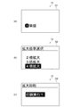
図4は、テープ印刷装置1の拡大印刷を行う際の表示部12の画面を表す説明図であり、図4(a)は、文字列入力画面を表す説明図であり、図4(b)は、拡大倍率を選択させる画面を表す説明図であり、図4(c)は、拡大印刷を実行させる画面を表す説明図である。
Next, enlarged printing will be described. First, operations and screen display when performing enlarged printing will be described.
FIG. 4 is an explanatory diagram illustrating a screen of the
図4(a)は、ユーザーに文字列を入力させる文字列入力画面G1である。文字列入力画面G1には、行番号を表す記号、およびユーザーによって入力された文字列が表示されている。文字列入力画面G1において、キーボード11に備わる拡大印刷キーが押下されると、拡大印刷における拡大倍率を選択させる拡大倍率選択画面が表示される。
FIG. 4A shows a character string input screen G1 that allows the user to input a character string. The character string input screen G1 displays a symbol representing a line number and a character string input by the user. When the enlargement print key provided on the
図4(b)は、拡大倍率選択画面G2である。拡大倍率選択画面G2の最上部には、拡大倍率選択画面であることを表す「拡大倍率選択」の文字列が表示されている。その下には、順番に、「2倍拡大」、「3倍拡大」、および「4倍拡大」の文字列が表示されている。ユーザーは、キーボード11に備わるカーソルキーを押下し、さらに決定キーを押下することで、「2倍拡大」、「3倍拡大」、および「4倍拡大」のいずれかを選択することができる。選択された拡大倍率はRAM32に記憶される。なお、選択中の項目は、白黒反転した文字で表示される。
FIG. 4B is an enlargement magnification selection screen G2. At the top of the enlargement magnification selection screen G2, a character string “enlargement magnification selection” indicating that it is an enlargement magnification selection screen is displayed. Below that, character strings of “2 times enlargement”, “3 times enlargement”, and “4 times enlargement” are displayed in order. The user can select any one of “2 times enlargement”, “3 times enlargement”, and “4 times enlargement” by pressing the cursor key provided on the
拡大倍率選択画面G2において、拡大倍率が選択されると、拡大印刷実行確認画面が表示される。
図4(c)は、拡大印刷実行確認画面G3を表す説明図である。拡大印刷実行確認画面G3の最上部には、拡大印刷実行確認画面であることを表す「拡大印刷」の文字列が表示されている。その下には、「印刷実行?」の文字列が白黒反転表示されている。ユーザーは、キーボード11に備わる決定キーを押下することで、拡大印刷を実行することができる。
When an enlargement magnification is selected on the enlargement magnification selection screen G2, an enlargement print execution confirmation screen is displayed.
FIG. 4C is an explanatory diagram showing an enlarged print execution confirmation screen G3. At the top of the enlarged print execution confirmation screen G3, a character string “enlarged print” representing the enlarged print execution confirmation screen is displayed. Below that, the character string “print execution?” Is displayed in black and white reversed. The user can execute enlarged printing by pressing a determination key provided on the
拡大印刷実行確認画面G3において、ユーザーによって拡大印刷が実行されると、テープ印刷装置1は、図5に示す拡大印刷処理(フローチャート)を実行する。
図5は、拡大印刷処理を説明するためのフローチャートである。図5を用いて、拡大印刷処理を説明する。
When enlargement printing is executed by the user on the enlargement printing execution confirmation screen G3, the
FIG. 5 is a flowchart for explaining the enlarged printing process. The enlarged printing process will be described with reference to FIG.
ユーザーによって拡大印刷が実行されると、制御部30は、識別センサー19からの情報に基づいて、装着されたテープカートリッジ2のテープ幅を検出する(ステップS101)。そして、制御部30は、レイアウト算出プログラム33aを実行することによって、拡大レイアウト情報を算出する(ステップS102)。具体的には、テープ幅、拡大倍率、入力された文字や図形とその大きさの設定情報、文字や図形に対する装飾の設定情報等に基づき、拡大印刷画像における文字や図形の配置座標を算出する。このときの制御部30がレイアウト算出部に相当する。
When enlargement printing is executed by the user, the
次に、制御部30は、余白判断プログラム33bを実行することによって、拡大印刷画像のテープ幅方向の上側余白がテープ幅以上か否かを判断する(ステップS103)。
Next, the
ここで、拡大印刷画像における余白とテープ幅について説明する。
図6は、印刷画像についての説明図であり、図6(a)は、通常印刷画像の説明図であり、図6(b)は、4倍拡大印刷画像の説明図である。
図6(a)に示すように、通常印刷画像(即ち拡大しない場合の印刷画像)D1では、印刷画像の幅がテープ幅Wを表している。実際には、テープ幅Wはドット数によって表される。
Here, the margin and the tape width in the enlarged print image will be described.
FIG. 6 is an explanatory diagram of a print image, FIG. 6 (a) is an explanatory diagram of a normal print image, and FIG. 6 (b) is an explanatory diagram of a 4 × enlarged print image.
As shown in FIG. 6A, in the normal print image (that is, the print image when not enlarged) D1, the width of the print image represents the tape width W. Actually, the tape width W is represented by the number of dots.
図6(b)に示すように、4倍拡大印刷画像D2では、拡大印刷画像の幅はテープ幅Wの4倍となっている。そして、上側余白Tmは、文字の上側の余白、即ち印刷対象となるドットが存在しない非印刷画像領域を表している。下側余白Bmは、文字の下側の余白を表している。なお、文字の上側や下側に文字を装飾するための外枠等が存在する場合には、上側余白Tmや下側余白Bmはその外枠の上側や下側の余白を表す。このような上側余白Tmや下側余白Bmは、拡大レイアウト情報に含まれる文字や図形の配置座標からドット数として算出することができる。そして、余白判断プログラム33bは、上側余白Tmや下側余白Bmがテープ幅W以上となっているか否かを判断する。
As shown in FIG. 6B, in the 4 × enlarged print image D2, the width of the enlarged print image is four times the tape width W. The upper margin Tm represents the upper margin of the character, that is, a non-print image area where there is no dot to be printed. The lower margin Bm represents the lower margin of the character. When an outer frame or the like for decorating the character exists above or below the character, the upper margin Tm or the lower margin Bm represents the upper or lower margin of the outer frame. Such upper margin Tm and lower margin Bm can be calculated as the number of dots from the arrangement coordinates of characters and figures included in the enlarged layout information. Then, the
図5に戻り、拡大印刷画像の上側余白Tmがテープ幅W以上の場合(ステップS103:YES)、制御部30は、上側余白削除フラグをオンにする(ステップS104)。拡大印刷画像の上側余白Tmがテープ幅W以上でない場合、即ちテープ幅W未満の場合(ステップS103:NO)、制御部30は、上側余白削除フラグをオフにする(ステップS105)。ここで、上側余白削除フラグは、RAM32に記憶されるフラグとする。
Returning to FIG. 5, when the upper margin Tm of the enlarged print image is equal to or greater than the tape width W (step S103: YES), the
次に、制御部30は、余白判断プログラム33bを実行することによって、拡大印刷画像のテープ幅方向の下側余白Bmがテープ幅W以上か否かを判断する(ステップS106)。拡大印刷画像の下側余白Bmがテープ幅W以上の場合(ステップS106:YES)、制御部30は、下側余白削除フラグをオンにする(ステップS107)。拡大印刷画像の下側余白Bmがテープ幅W以上でない場合、即ちテープ幅W未満の場合(ステップS106:NO)、制御部30は、下側余白削除フラグをオフにする(ステップS108)。ここで、下側余白削除フラグは、RAM32に記憶されるフラグとする。このように上側余白Tmおよび下側余白Bmを算出して、テープ幅W以上か否かを判断する際の制御部30が、余白判断部に相当する。
Next, the
制御部30は、画像データ生成プログラム33cを実行することによって、拡大印刷画像の画像データを生成する(ステップS109)。具体的には、制御部30は、CGROM34から文字や図形等のフォントデータを取得し、拡大レイアウト情報に基づいた配置座標に配置することで画像データを生成する。このとき、拡大印刷画像の画像データには上側余白Tmおよび下側余白Bmも含まれている。このときの制御部30が画像データ生成部に相当する。
The
制御部30は、上側余白削除フラグおよび下側余白削除フラグを確認し、削除可能な余白があるか否かを判断する(ステップS110)。削除可能な余白がある場合(ステップS110:YES)、制御部30は、印刷プログラム33dを実行し、削除可能な余白に相当するテープ部分を除いて、拡大印刷画像の画像データをテープTに順次印刷する(ステップS111)。具体的には、制御部30は、拡大印刷画像の画像データをテープ幅方向の上側から順番に印刷するが、削除可能な余白に相当するテープ幅分については印刷を行わないようにする。そして、制御部30は、ヘッド駆動部42および搬送駆動部43にそれぞれサーマルヘッド15および搬送機構16を駆動させ、画像データに応じた画像をテープTに印刷させる。その後、制御部30が、カッター駆動部44にカッターユニット18を駆動させると、テープTは切断される。この動作を順次実行する。このときの制御部30、ヘッド駆動部42、搬送駆動部43、サーマルヘッド15、および搬送機構16が印刷部に相当する。そして、拡大印刷処理を終了する。
The
削除可能な余白がない場合(ステップS110:NO)、制御部30は、拡大印刷画像の全ての画像データをテープTに順次印刷する(ステップS112)。そして、拡大印刷処理を終了する。
When there is no erasable margin (step S110: NO), the
ここで、テープ印刷装置1の印刷によって形成される印刷ラベルについて説明する。
図7は、印刷がなされたラベルを示す平面図であり、図7(a)は、通常印刷がなされたラベルの平面図であり、図7(b)は、拡大印刷において余白に相当するテープ部分が印刷された場合のラベルの平面図であり、図7(c)は、拡大印刷において余白に相当するテープ部分を印刷しないラベルの平面図である。
Here, a print label formed by printing of the
FIG. 7 is a plan view showing a printed label, FIG. 7 (a) is a plan view of a label that is normally printed, and FIG. 7 (b) is a tape corresponding to a margin in enlarged printing. FIG. 7C is a plan view of a label that does not print a tape portion corresponding to a margin in enlarged printing.
図7(a)に示すように、通常印刷において印刷がなされた通常印刷ラベルL1は、図6(a)で示した通常印刷画像D1に基づいて印刷された1枚のラベルである。
一方、図7(b)は、従来のテープ印刷装置で拡大倍率を4倍として拡大印刷がなされた4倍拡大印刷ラベル(テープ部分L21,L22,L23,L24)である。図7(b)に示すように、テープ部分L21は上側余白Tmに相当し、テープ部分L24は下側余白Bmに相当しており、共に印刷対象となるドットが存在していない。このため、テープ部分L21およびテープ部分L24は、印刷出力されても、ユーザーに使用されない場合がある。
As shown in FIG. 7A, the normal printing label L1 printed in the normal printing is one label printed based on the normal printing image D1 shown in FIG.
On the other hand, FIG. 7B is a 4 × enlargement print label (tape portions L21, L22, L23, L24) that has been enlarged and printed with a conventional tape printer with an enlargement magnification of 4. As shown in FIG. 7B, the tape portion L21 corresponds to the upper margin Tm, the tape portion L24 corresponds to the lower margin Bm, and there are no dots to be printed. For this reason, the tape portion L21 and the tape portion L24 may not be used by the user even if printed out.
本実施形態のテープ印刷装置1では、図7(c)に示すように、テープ部分L21およびテープ部分L24の印刷出力は行わず、テープ部分L22およびテープ部分L23の印刷出力のみを行うことができる。
In the
上述した第1の実施形態によれば、以下の効果が得られる。
(1)テープ印刷装置1は、テープ幅W以上となっている余白に相当するテープ部分を除いて、拡大印刷画像の画像データを順次印刷する。これにより、上側余白Tmや下側余白Bmがテープ幅W以上となる場合には、上側余白Tmや下側余白Bmに相当するテープ部分は、印刷出力されないため、拡大印刷においてテープTの使用量を削減することができる。
According to the first embodiment described above, the following effects can be obtained.
(1) The
(2)テープ印刷装置1は、拡大印刷において、テープ幅Wが狭いテープカートリッジ2を使用する場合に、上側余白Tmや下側余白Bmがテープ幅W以上となる可能性が高くなる。よって、テープ幅Wが狭いテープカートリッジ2を使用する場合に、テープTの使用量の削減の効果が高まる。つまり、限られたテープカートリッジ2を用いて拡大印刷を行う場合において、テープTの使用量を削減することができる。
(2) When the
(3)テープ印刷装置1は、テープ幅Wに対して小さな文字や図形を拡大印刷させる場合に、上側余白Tmや下側余白Bmがテープ幅W以上となる可能性が高くなる。よって、テープTの使用量の削減の効果が高まる。
(3) When the
(第2の実施形態)
以下、第2の実施形態について説明する。
(Second Embodiment)
Hereinafter, the second embodiment will be described.
第2の実施形態では、拡大印刷の際にテープ幅W以上となっている余白に相当するテープ部分を除いた拡大印刷画像の画像データを生成するテープ印刷装置100について説明する。
In the second embodiment, a
第2の実施形態に係るテープ印刷装置100の外観および機構は、第1の実施形態に係るテープ印刷装置1と同様である。よって、説明は省略する。また、第2の実施形態に係るテープ印刷装置100の回路構成を示すブロック図も、第1の実施形態に係るテープ印刷装置1と同様である。よって、説明は省略する。また、第2の実施形態に係るテープ印刷装置100の拡大印刷を行う際の操作と画面表示も第1の実施形態に係るテープ印刷装置1と同様である。よって、説明は省略する。
The appearance and mechanism of the
次に、第2の実施形態に係るテープ印刷装置100における拡大印刷処理について説明する。第1の実施形態と同様に、拡大印刷実行確認画面G3において、ユーザーによって拡大印刷が実行されると、テープ印刷装置100は、図8に示す拡大印刷処理(フローチャート)を実行する。
図8は、第2の実施形態に係る拡大印刷処理を説明するためのフローチャートである。図8を用いて、拡大印刷処理を説明する。
Next, an enlarged printing process in the
FIG. 8 is a flowchart for explaining the enlarged printing process according to the second embodiment. The enlarged printing process will be described with reference to FIG.
ユーザーによって拡大印刷が実行されると、制御部30は、識別センサー19からの情報に基づいて、装着されたテープカートリッジ2のテープ幅を検出する(ステップS201)。そして、制御部30は、レイアウト算出プログラム33aを実行することによって、第1の拡大レイアウト情報を算出する(ステップS202)。具体的には、テープ幅、拡大倍率、入力された文字や図形とその大きさの設定情報、文字や図形に対する装飾の設定情報等に基づき、拡大印刷画像における文字や図形の配置座標を算出する。このときの制御部30が第1レイアウト算出部に相当する。
When enlargement printing is executed by the user, the
次に、制御部30は、余白判断プログラム33bを実行することによって、拡大印刷画像のテープ幅方向の上側余白Tmがテープ幅W以上か否かを判断する(ステップS203)。ここで、余白判断プログラム33bが実行する、上側余白Tmや下側余白Bmがテープ幅W以上となっているか否かの判断処理は、第1の実施形態と同様である。
Next, the
拡大印刷画像の上側余白Tmがテープ幅W以上の場合(ステップS203:YES)、制御部30は、上側余白削除フラグをオンにする(ステップS204)。拡大印刷画像の上側余白Tmがテープ幅W以上でない場合、即ちテープ幅W未満の場合(ステップS203:NO)、制御部30は、上側余白削除フラグをオフにする(ステップS205)。
When the upper margin Tm of the enlarged print image is greater than or equal to the tape width W (step S203: YES), the
次に、制御部30は、余白判断プログラム33bを実行することによって、拡大印刷画像のテープ幅方向の下側余白Bmがテープ幅W以上か否かを判断する(ステップS206)。拡大印刷画像の下側余白Bmがテープ幅W以上の場合(ステップS206:YES)、制御部30は、下側余白削除フラグをオンにする(ステップS207)。拡大印刷画像の下側余白Bmがテープ幅W以上でない場合、即ちテープ幅W未満の場合(ステップS206:NO)、制御部30は、下側余白削除フラグをオフにする(ステップS208)。このように上側余白Tmおよび下側余白Bmを算出して、テープ幅W以上か否かを判断する際の制御部30が余白判断部に相当する。
Next, the
制御部30は、上側余白削除フラグおよび下側余白削除フラグを確認し、削除可能な余白があるか否かを判断する(ステップS209)。削除可能な余白がある場合(ステップS209:YES)、制御部30は、レイアウト算出プログラム33aを実行することによって、削除可能な余白に相当するテープ部分を除いた第2の拡大レイアウト情報を算出する(ステップS210)。具体的には、第1の拡大レイアウト情報から、削除可能な上側余白Tmに相当するテープ部分のテープ幅W、および削除可能な下側余白Bmに相当するテープ部分のテープ幅Wを削除した拡大レイアウト情報を算出する。このときの制御部30が第2レイアウト算出部に相当する。
削除可能な余白がない場合(ステップS209:NO)、制御部30は、ステップS210の処理は行わない。
The
When there is no erasable margin (step S209: NO), the
次に制御部30は、画像データ生成プログラム33cを実行することによって、拡大印刷画像の画像データを生成する(ステップS211)。このとき、第2の拡大レイアウト情報が算出されていれば、第2の拡大レイアウト情報に基づいて拡大印刷画像の画像データを生成し、第2の拡大レイアウト情報が算出されていなければ、第1の拡大レイアウト情報に基づいて拡大印刷画像の画像データを生成する。このときの制御部30が画像データ生成部に相当する。
Next, the
ここで、上側余白Tmに相当するテープ部分のテープ幅W、および下側余白Bmに相当するテープ部分のテープ幅Wが削除可能な場合に生成された、拡大印刷画像の画像データについて説明する。
図9は、余白テープ部分が削除された拡大印刷画像についての説明図である。図9に示すように、4倍拡大印刷画像D3は4倍の拡大印刷画像であるが、上側余白Tmに相当するテープ部分のテープ幅W、および下側余白Bmに相当するテープ部分のテープ幅Wが削除されているため、拡大印刷画像の幅はテープ幅Wの2倍となっている。
Here, the image data of the enlarged print image generated when the tape width W of the tape portion corresponding to the upper margin Tm and the tape width W of the tape portion corresponding to the lower margin Bm can be deleted will be described.
FIG. 9 is an explanatory diagram of an enlarged print image from which the blank tape portion has been deleted. As shown in FIG. 9, the 4 × enlarged print image D3 is a 4 × enlarged print image, but the tape width W of the tape portion corresponding to the upper margin Tm and the tape width of the tape portion corresponding to the lower margin Bm. Since W is deleted, the width of the enlarged print image is twice the tape width W.
図8に戻り、制御部30は、印刷プログラム33dを実行することによって、拡大印刷画像の全ての画像データを順次印刷する(ステップS212)。この印刷時の制御部30、ヘッド駆動部42、搬送駆動部43、サーマルヘッド15、および搬送機構16が印刷部に相当する。ここで、図9で示したように、上側余白Tmに相当するテープ部分のテープ幅W、および下側余白Bmに相当するテープ部分のテープ幅Wが削除可能な場合には、印刷ラベルは2枚となる。そして、拡大印刷処理を終了する。
Returning to FIG. 8, the
テープ印刷装置100の印刷によって形成される印刷ラベルは、図7(c)と同様に、テープ部分L22およびテープ部分L23のみとなる。
The print labels formed by the printing of the
上述した第2の実施形態によれば、第1の実施形態の効果(2)、(3)と同様の効果を奏することができる。他に以下の効果が得られる。
(1)テープ印刷装置100は、テープ幅W以上となっている余白に相当するテープ幅分の印刷画像を除いた拡大印刷画像の画像データを生成する。そして、拡大印刷画像の画像データを順次印刷する。これにより、上側余白Tmや下側余白Bmがテープ幅W以上となる場合には、上側余白Tmや下側余白Bmに相当するテープ部分は、印刷出力されないため、拡大印刷においてテープTの使用量を削減することができる。また、拡大印刷画像の画像データ生成時のメモリー使用量を削減することができる。
According to the second embodiment described above, the same effects as the effects (2) and (3) of the first embodiment can be achieved. In addition, the following effects can be obtained.
(1) The
また、上述した実施形態は、上記機能を実現するためのプログラムをコンピューターで読み取り可能に記録した記録媒体等の態様で構成することも可能である。記録媒体としては、フレキシブルディスクやハードディスク、CDやDVD等の光ディスク、光磁気ディスク、不揮発性の半導体メモリーを搭載したメモリーカードやUSBメモリー、画像生成装置の内部記憶装置(RAMやROM等の半導体メモリー)等、前記コンピューターが読み取り可能な種々の媒体を利用することができる。 In addition, the above-described embodiment can be configured in the form of a recording medium or the like in which a program for realizing the above functions is recorded so as to be readable by a computer. Recording media include flexible disks, hard disks, optical disks such as CDs and DVDs, magneto-optical disks, memory cards and USB memories equipped with non-volatile semiconductor memory, and internal storage devices for image generation devices (semiconductor memories such as RAM and ROM). ) And the like can be used.
なお、上述した実施形態に限定されず、種々の変更や改良等を加えて実施することが可能である。変形例を以下に述べる。 In addition, it is not limited to embodiment mentioned above, It is possible to implement by adding various change, improvement, etc. A modification will be described below.
(変形例1)上記実施形態では、拡大印刷の際の上側余白Tmや下側余白Bmはテープ幅W以上として、上側および下側のテープ部分の1枚分を削除して印刷する場合について説明したが、上側余白Tmや下側余白Bmがテープ幅Wのn倍(n≧1)以上である場合には、上側および下側のテープ部分のn枚分を削除して印刷してもよい。こうすれば、テープTの使用量をさらに削減することができる。 (Modification 1) In the embodiment described above, the upper margin Tm and the lower margin Bm at the time of enlarged printing are set to be equal to or larger than the tape width W, and printing is performed by deleting one of the upper and lower tape portions. However, when the upper margin Tm and the lower margin Bm are n times (n ≧ 1) or more of the tape width W, the upper and lower tape portions of n sheets may be deleted and printed. . In this way, the usage amount of the tape T can be further reduced.
(変形例2)上記実施形態では、拡大印刷における選択可能な拡大倍率は、「2倍拡大」、「3倍拡大」、および「4倍拡大」としているが、これ以外の拡大倍率としてもよい。 (Modification 2) In the above embodiment, the selectable enlargement magnification in enlargement printing is “2 times enlargement”, “3 times enlargement”, and “4 times enlargement”, but other enlargement magnifications may be used. .
(変形例3)上記実施形態では、テープTに文字等を印刷するための印刷方式として、サーマルヘッド15による熱転写方式を用いているが、この方式に限られず、インク滴を吐出するインクジェット方式等、他の印刷方式を用いてもよい。
(Modification 3) In the above embodiment, the thermal transfer method using the
1,100…テープ印刷装置、2…テープカートリッジ、10…筐体、11…キーボード、12…表示部、15…サーマルヘッド、16…搬送機構、18…カッターユニット、19…識別センサー、30…制御部、31…CPU、32…RAM、33…ROM、33a…レイアウト算出プログラム、33b…余白判断プログラム、33c…画像データ生成プログラム、33d…印刷プログラム、34…CGROM、35…入力インターフェイス、36…出力インターフェイス、41…表示駆動部、42…ヘッド駆動部、43…搬送駆動部、44…カッター駆動部。 DESCRIPTION OF SYMBOLS 1,100 ... Tape printer, 2 ... Tape cartridge, 10 ... Housing | casing, 11 ... Keyboard, 12 ... Display part, 15 ... Thermal head, 16 ... Conveyance mechanism, 18 ... Cutter unit, 19 ... Identification sensor, 30 ... Control , 31 ... CPU, 32 ... RAM, 33 ... ROM, 33a ... layout calculation program, 33b ... margin determination program, 33c ... image data generation program, 33d ... print program, 34 ... CGROM, 35 ... input interface, 36 ... output Interface, 41 ... display drive unit, 42 ... head drive unit, 43 ... transport drive unit, 44 ... cutter drive unit.
Claims (6)
前記テープ幅を検出するテープ幅検出部と、
前記拡大印刷画像を構成する文字や図形の配置を示す拡大レイアウト情報を算出するレイアウト算出部と、
前記レイアウト算出部が算出した前記拡大レイアウト情報に基づいて、前記拡大印刷画像のテープ幅方向の上側余白および下側余白の幅を算出し、それぞれの幅が前記テープ幅以上か否かを判断する余白判断部と、
前記拡大レイアウト情報に基づいて前記拡大印刷画像の画像データを生成する画像データ生成部と、
前記余白判断部の判断結果に基づいて、前記テープ幅以上となっている余白に相当するテープ部分を除いて、前記拡大印刷画像の画像データを1または複数のテープ部分に順次印刷する印刷部と、
を備えることを特徴とするテープ印刷装置。 The enlarged print image larger than the tape width of the long tape is divided into a plurality of pieces and sequentially printed on a plurality of tape portions, and a plurality of print labels formed by printing are arranged side by side in the tape width direction. A tape printer having an enlarged printing function for forming an image,
A tape width detector for detecting the tape width;
A layout calculating unit that calculates enlarged layout information indicating the arrangement of characters and figures constituting the enlarged print image;
Based on the enlarged layout information calculated by the layout calculating unit, the width of the upper margin and the lower margin in the tape width direction of the enlarged print image is calculated, and it is determined whether or not each width is equal to or greater than the tape width. A margin determination unit;
An image data generation unit that generates image data of the enlarged print image based on the enlarged layout information;
A printing unit that sequentially prints image data of the enlarged print image on one or a plurality of tape portions, excluding a tape portion corresponding to a margin that is equal to or larger than the tape width, based on a determination result of the margin determination portion; ,
A tape printing apparatus comprising:
前記テープ幅を検出するテープ幅検出部と、
前記拡大印刷画像を構成する文字や図形の配置を示す第1の拡大レイアウト情報を算出する第1レイアウト算出部と、
前記第1のレイアウト算出部が算出した前記第1の拡大レイアウト情報に基づいて、前記拡大印刷画像のテープ幅方向の上側余白および下側余白の幅を算出し、それぞれの幅が前記テープ幅以上か否かを判断する余白判断部と、
前記余白判断部の判断結果に基づいて、前記第1の拡大レイアウト情報から、前記テープ幅以上となっている余白に相当するテープ幅分の印刷画像部分を除いた第2の拡大レイアウト情報を算出する第2レイアウト算出部と、
前記第2レイアウト算出部が算出した前記第2の拡大レイアウト情報に基づいて、拡大印刷画像の画像データを生成する画像データ生成部と、
前記拡大印刷画像の画像データを1または複数のテープ部分に順次印刷する印刷部と、
を備えることを特徴とするテープ印刷装置。 The enlarged print image larger than the tape width of the long tape is divided into a plurality of pieces and sequentially printed on a plurality of tape portions, and a plurality of print labels formed by printing are arranged side by side in the tape width direction. A tape printer having an enlarged printing function for forming an image,
A tape width detector for detecting the tape width;
A first layout calculating unit that calculates first enlarged layout information indicating an arrangement of characters and figures constituting the enlarged print image;
Based on the first enlarged layout information calculated by the first layout calculating unit, the width of the upper margin and the lower margin in the tape width direction of the enlarged print image is calculated, and each width is equal to or larger than the tape width. A margin judgment unit for judging whether or not
Based on the determination result of the margin determination unit, second enlarged layout information is calculated by removing, from the first enlarged layout information, a print image portion corresponding to a tape width corresponding to a margin equal to or larger than the tape width. A second layout calculation unit that
An image data generation unit that generates image data of an enlarged print image based on the second enlarged layout information calculated by the second layout calculation unit;
A printing unit that sequentially prints image data of the enlarged print image on one or a plurality of tape portions;
A tape printing apparatus comprising:
前記テープ幅を検出するテープ幅検出ステップと、
前記拡大印刷画像を構成する文字や図形の配置を示す拡大レイアウト情報を算出するレイアウト算出ステップと、
前記レイアウト算出ステップによって算出された前記拡大レイアウト情報に基づいて、前記拡大印刷画像のテープ幅方向の上側余白および下側余白の幅を算出し、それぞれの余白の幅が前記テープ幅以上か否かを判断する余白判断ステップと、
前記拡大レイアウト情報に基づいて前記拡大印刷画像の画像データを生成する画像データ生成ステップと、
前記余白判断ステップによる判断結果に基づいて、前記テープ幅以上となっている余白に相当するテープ部分を除いて、前記拡大印刷画像の画像データを1または複数のテープ部分に順次印刷する印刷ステップと、
を備えることを特徴とするテープ印刷装置の制御方法。 The enlarged print image larger than the tape width of the long tape is divided into a plurality of pieces and sequentially printed on a plurality of tape portions, and a plurality of print labels formed by printing are arranged side by side in the tape width direction. A control method of a tape printer having an enlarged printing function for forming an image,
A tape width detecting step for detecting the tape width;
A layout calculating step for calculating enlarged layout information indicating an arrangement of characters and figures constituting the enlarged print image;
Based on the enlarged layout information calculated by the layout calculating step, the width of the upper margin and the lower margin in the tape width direction of the enlarged print image is calculated, and whether or not each margin width is equal to or larger than the tape width. Margin determination step for determining
An image data generation step for generating image data of the enlarged print image based on the enlarged layout information;
A printing step of sequentially printing image data of the enlarged print image on one or a plurality of tape portions, excluding a tape portion corresponding to a margin that is equal to or larger than the tape width, based on a determination result by the margin determination step; ,
A control method for a tape printer, comprising:
前記テープ幅を検出するテープ幅検出ステップと、
前記拡大印刷画像を構成する文字や図形の配置を示す第1の拡大レイアウト情報を算出する第1レイアウト算出ステップと、
前記第1レイアウト算出ステップによって算出された前記第1の拡大レイアウト情報に基づいて、前記拡大印刷画像のテープ幅方向の上側余白および下側余白の幅を算出し、それぞれの幅が前記テープ幅以上か否かを判断する余白判断ステップと、
前記余白判断ステップによる判断結果に基づいて、前記第1の拡大レイアウト情報から、前記テープ幅以上となっている余白に相当するテープ幅分の印刷画像部分を除いた第2の拡大レイアウト情報を算出する第2レイアウト算出ステップと、
前記第2レイアウト算出ステップにより算出された前記第2の拡大レイアウト情報に基づいて、拡大印刷画像の画像データを生成する画像データ生成ステップと、
前記拡大印刷画像の画像データを1または複数のテープ部分に順次印刷する印刷ステップと、
を備えることを特徴とするテープ印刷装置の制御方法。 The enlarged print image larger than the tape width of the long tape is divided into a plurality of pieces and sequentially printed on a plurality of tape portions, and a plurality of print labels formed by printing are arranged side by side in the tape width direction. A control method of a tape printer having an enlarged printing function for forming an image,
A tape width detecting step for detecting the tape width;
A first layout calculating step of calculating first enlarged layout information indicating an arrangement of characters and figures constituting the enlarged print image;
Based on the first enlarged layout information calculated by the first layout calculating step, the width of the upper margin and the lower margin in the tape width direction of the enlarged print image is calculated, and each width is equal to or greater than the tape width. Margin determination step for determining whether or not,
Based on the determination result in the margin determination step, second expanded layout information is calculated by removing a print image portion corresponding to a tape width corresponding to a margin equal to or larger than the tape width from the first expanded layout information. A second layout calculating step,
An image data generating step for generating image data of an enlarged print image based on the second enlarged layout information calculated by the second layout calculating step;
A printing step of sequentially printing image data of the enlarged print image on one or a plurality of tape portions;
A control method for a tape printer, comprising:
Priority Applications (6)
| Application Number | Priority Date | Filing Date | Title |
|---|---|---|---|
| JP2010055461A JP2011189534A (en) | 2010-03-12 | 2010-03-12 | Tape printer, method for controlling the same and program |
| EP11156366.4A EP2364856A3 (en) | 2010-03-12 | 2011-03-01 | Tape printer, method for controlling tape printer, and program product |
| US13/041,555 US20110222946A1 (en) | 2010-03-12 | 2011-03-07 | Tape printer, method for controlling tape printer, and computer program product |
| KR1020110021035A KR101272863B1 (en) | 2010-03-12 | 2011-03-09 | Tape printer, method for controlling tape printer, and recording medium having computer program thereon |
| TW100107966A TWI435810B (en) | 2010-03-12 | 2011-03-09 | Tape printer, and method for controlling tape printer |
| CN2011100596622A CN102189819B (en) | 2010-03-12 | 2011-03-11 | Tape printer and method for controlling tape printer |
Applications Claiming Priority (1)
| Application Number | Priority Date | Filing Date | Title |
|---|---|---|---|
| JP2010055461A JP2011189534A (en) | 2010-03-12 | 2010-03-12 | Tape printer, method for controlling the same and program |
Publications (2)
| Publication Number | Publication Date |
|---|---|
| JP2011189534A true JP2011189534A (en) | 2011-09-29 |
| JP2011189534A5 JP2011189534A5 (en) | 2012-11-29 |
Family
ID=44168215
Family Applications (1)
| Application Number | Title | Priority Date | Filing Date |
|---|---|---|---|
| JP2010055461A Withdrawn JP2011189534A (en) | 2010-03-12 | 2010-03-12 | Tape printer, method for controlling the same and program |
Country Status (6)
| Country | Link |
|---|---|
| US (1) | US20110222946A1 (en) |
| EP (1) | EP2364856A3 (en) |
| JP (1) | JP2011189534A (en) |
| KR (1) | KR101272863B1 (en) |
| CN (1) | CN102189819B (en) |
| TW (1) | TWI435810B (en) |
Cited By (1)
| Publication number | Priority date | Publication date | Assignee | Title |
|---|---|---|---|---|
| JP2011201227A (en) * | 2010-03-26 | 2011-10-13 | Seiko Epson Corp | Tape printer, method for controlling tape printer, and program |
Families Citing this family (6)
| Publication number | Priority date | Publication date | Assignee | Title |
|---|---|---|---|---|
| JP5914983B2 (en) * | 2011-04-27 | 2016-05-11 | セイコーエプソン株式会社 | Tape printing apparatus and display method in tape printing apparatus |
| JP5769015B2 (en) * | 2011-09-20 | 2015-08-26 | カシオ計算機株式会社 | Printing apparatus, printing method, and program |
| CN104063190B (en) * | 2013-03-19 | 2017-06-30 | 卡西欧计算机株式会社 | Data processing equipment, printing equipment, data processing method and storage medium |
| JP6144093B2 (en) * | 2013-04-12 | 2017-06-07 | セイコーエプソン株式会社 | Label data generation method, program, label data generation apparatus, and label generation system |
| JP6455345B2 (en) * | 2015-06-30 | 2019-01-23 | ブラザー工業株式会社 | Printing device |
| JP7314505B2 (en) * | 2018-12-18 | 2023-07-26 | カシオ計算機株式会社 | Program, print data generation device, and print data generation method |
Citations (2)
| Publication number | Priority date | Publication date | Assignee | Title |
|---|---|---|---|---|
| JPH0852906A (en) * | 1994-08-10 | 1996-02-27 | Brother Ind Ltd | Printing data forming apparatus |
| JP2008238492A (en) * | 2007-03-26 | 2008-10-09 | Casio Comput Co Ltd | Printing apparatus, its printing method, and printing processing program |
Family Cites Families (16)
| Publication number | Priority date | Publication date | Assignee | Title |
|---|---|---|---|---|
| JP2995314B2 (en) * | 1992-10-15 | 1999-12-27 | カシオ計算機株式会社 | Tape cassette and printing device |
| JP2940404B2 (en) * | 1994-08-10 | 1999-08-25 | ブラザー工業株式会社 | Label making device |
| DE69535836D1 (en) * | 1994-11-29 | 2008-10-23 | Seiko Epson Corp | Tape printing device |
| JP3911726B2 (en) * | 1996-07-23 | 2007-05-09 | カシオ計算機株式会社 | Tape printer |
| JP3693429B2 (en) * | 1996-08-20 | 2005-09-07 | 株式会社キングジム | Tape printer |
| JP3399332B2 (en) | 1997-11-27 | 2003-04-21 | セイコーエプソン株式会社 | Method of creating divided image in tape printing apparatus, method of printing divided image, and apparatuses thereof |
| JP3397111B2 (en) * | 1997-11-27 | 2003-04-14 | セイコーエプソン株式会社 | Method of creating divided image in tape printing apparatus, method of printing divided image, and apparatuses thereof |
| JP3899656B2 (en) * | 1998-03-31 | 2007-03-28 | ブラザー工業株式会社 | Tape printer |
| KR100385062B1 (en) * | 2001-09-20 | 2003-05-23 | 삼성전자주식회사 | Printer and Apparatus for controlling outputting Printing data capable of preventing printing about page of data nonexisting |
| KR100524023B1 (en) * | 2003-07-04 | 2005-10-26 | 삼성전자주식회사 | Wide page printing system and method |
| JP2005022332A (en) * | 2003-07-04 | 2005-01-27 | Canon Finetech Inc | Information processor, image recording device, picture recording system, and their controlling method |
| JP2007203676A (en) * | 2006-02-03 | 2007-08-16 | King Jim Co Ltd | Tape printing system |
| JP2008238580A (en) * | 2007-03-27 | 2008-10-09 | Casio Comput Co Ltd | Printer, printing method, and print processing program |
| JP5067005B2 (en) * | 2007-05-14 | 2012-11-07 | セイコーエプソン株式会社 | Image data generation apparatus, tape printing apparatus, printing system, and program |
| JP4792004B2 (en) | 2007-05-14 | 2011-10-12 | 株式会社キングジム | Image data generation apparatus, tape printing apparatus, printing system, and program |
| TWI330140B (en) * | 2007-12-28 | 2010-09-11 | Teco Image Sys Co Ltd | Control module and method for printing poster and mfp |
-
2010
- 2010-03-12 JP JP2010055461A patent/JP2011189534A/en not_active Withdrawn
-
2011
- 2011-03-01 EP EP11156366.4A patent/EP2364856A3/en not_active Withdrawn
- 2011-03-07 US US13/041,555 patent/US20110222946A1/en not_active Abandoned
- 2011-03-09 KR KR1020110021035A patent/KR101272863B1/en active IP Right Grant
- 2011-03-09 TW TW100107966A patent/TWI435810B/en active
- 2011-03-11 CN CN2011100596622A patent/CN102189819B/en active Active
Patent Citations (2)
| Publication number | Priority date | Publication date | Assignee | Title |
|---|---|---|---|---|
| JPH0852906A (en) * | 1994-08-10 | 1996-02-27 | Brother Ind Ltd | Printing data forming apparatus |
| JP2008238492A (en) * | 2007-03-26 | 2008-10-09 | Casio Comput Co Ltd | Printing apparatus, its printing method, and printing processing program |
Cited By (1)
| Publication number | Priority date | Publication date | Assignee | Title |
|---|---|---|---|---|
| JP2011201227A (en) * | 2010-03-26 | 2011-10-13 | Seiko Epson Corp | Tape printer, method for controlling tape printer, and program |
Also Published As
| Publication number | Publication date |
|---|---|
| CN102189819A (en) | 2011-09-21 |
| KR20110103337A (en) | 2011-09-20 |
| US20110222946A1 (en) | 2011-09-15 |
| TW201200366A (en) | 2012-01-01 |
| EP2364856A3 (en) | 2014-04-23 |
| CN102189819B (en) | 2013-11-13 |
| TWI435810B (en) | 2014-05-01 |
| EP2364856A2 (en) | 2011-09-14 |
| KR101272863B1 (en) | 2013-06-10 |
Similar Documents
| Publication | Publication Date | Title |
|---|---|---|
| JP4862271B2 (en) | Label making device | |
| KR101272863B1 (en) | Tape printer, method for controlling tape printer, and recording medium having computer program thereon | |
| JP3945165B2 (en) | Text data processing device | |
| JP5505022B2 (en) | Tape printer, control method of tape printer, and program | |
| JP2008021248A (en) | Tape printer and tape printing program | |
| JP5914983B2 (en) | Tape printing apparatus and display method in tape printing apparatus | |
| JP2012121216A (en) | Tape printer, control method for tape printer, and program | |
| JP4075076B2 (en) | Tape printer | |
| JP5772045B2 (en) | Tape printer, control method of tape printer, and program | |
| US20020178189A1 (en) | Text control method and apparatus | |
| JP2010241102A (en) | Printer, tape printer, and printer control method | |
| JP2011011450A (en) | Tape printer and method for controlling the same | |
| US10671898B2 (en) | Tape cassette and printing apparatus | |
| JP2011240505A (en) | Tape printing device, method of controlling the same, and program | |
| JP2011116022A (en) | Tape printer, method for controlling the tape printer, and program | |
| JP6812924B2 (en) | Printing processing program and printing equipment | |
| JP3767563B2 (en) | Tape printer | |
| JP4544000B2 (en) | Label making device | |
| JP2010020373A (en) | Tape printer, character string conversion device, and character string conversion method | |
| JP2011251484A (en) | Tape printing device, method for controlling the same and program | |
| JP2014008723A (en) | Tape-like printing medium, tape cartridge, tape printer and control method of tape printer | |
| JP2012131048A (en) | Document processing device, tape printing device, control method of them, and program | |
| JP2012113463A (en) | Document processing apparatus, tape printing apparatus, control method of document processing apparatus and program | |
| JPH11105326A (en) | Thermal transfer recording apparatus | |
| JP2006102951A (en) | Printer |
Legal Events
| Date | Code | Title | Description |
|---|---|---|---|
| A521 | Written amendment |
Free format text: JAPANESE INTERMEDIATE CODE: A523 Effective date: 20121017 |
|
| A621 | Written request for application examination |
Free format text: JAPANESE INTERMEDIATE CODE: A621 Effective date: 20121017 |
|
| A977 | Report on retrieval |
Free format text: JAPANESE INTERMEDIATE CODE: A971007 Effective date: 20131115 |
|
| A131 | Notification of reasons for refusal |
Free format text: JAPANESE INTERMEDIATE CODE: A131 Effective date: 20131119 |
|
| A761 | Written withdrawal of application |
Free format text: JAPANESE INTERMEDIATE CODE: A761 Effective date: 20140106 |