JP2011174635A - Boiler piping structure - Google Patents
Boiler piping structure Download PDFInfo
- Publication number
- JP2011174635A JP2011174635A JP2010037704A JP2010037704A JP2011174635A JP 2011174635 A JP2011174635 A JP 2011174635A JP 2010037704 A JP2010037704 A JP 2010037704A JP 2010037704 A JP2010037704 A JP 2010037704A JP 2011174635 A JP2011174635 A JP 2011174635A
- Authority
- JP
- Japan
- Prior art keywords
- boiler
- boiler pipe
- corrosion
- heat transfer
- pipe
- Prior art date
- Legal status (The legal status is an assumption and is not a legal conclusion. Google has not performed a legal analysis and makes no representation as to the accuracy of the status listed.)
- Withdrawn
Links
Images


Landscapes
- Heat-Exchange Devices With Radiators And Conduit Assemblies (AREA)
Abstract
Description
本発明は、ボイラ管の配管構造に係り、特に、熱交換部を有するボイラ内に複数設けられるボイラ管の配管構造に関する。 The present invention relates to a piping structure for a boiler pipe, and more particularly to a piping structure for a boiler pipe provided in a boiler having a heat exchange section.
熱交換部を有するボイラ内に複数設けられるボイラ管(伝熱管)には、排ガスとボイラ管内の水とが熱交換する過程で燃焼灰の付着およびスケールの生成といった現象が起こる。ボイラ管に付着した燃焼灰やスケールは、ボイラ管の熱交換率を悪化させるだけでなく、ボイラ管を腐食させる恐れがある。これを防止するために、従来、ボイラ管の表面には、耐食性を有する溶射材料が溶射されるようになっている。 A plurality of boiler tubes (heat transfer tubes) provided in a boiler having a heat exchanging unit undergo phenomena such as adhesion of combustion ash and generation of scale in the process of heat exchange between exhaust gas and water in the boiler tube. The combustion ash and scale adhering to the boiler pipe not only deteriorate the heat exchange rate of the boiler pipe, but may corrode the boiler pipe. In order to prevent this, conventionally, a spray material having corrosion resistance is sprayed on the surface of the boiler tube.
産業用ボイラの耐食・耐磨耗溶射材料としては、例えば、Ni−50CrのようなNi基材料やCr3C2/NiCrのような金属炭化物を主成分とした材料が用いられ、様々な溶射法によりコーティングされてきた。 As an anti-corrosion / abrasion-resistant spraying material for industrial boilers, for example, a Ni-based material such as Ni-50Cr or a material mainly composed of a metal carbide such as Cr 3 C 2 / NiCr is used. It has been coated by the method.
しかし、これら耐食・耐磨耗溶射材料は、高い耐食性と耐磨耗性を有するものの、高価なニッケルや金属炭化物を含むため、ボイラの構成部材のような広い面積を対象とする場合、高コストになってしまうという問題がある。 However, although these corrosion-resistant and wear-resistant thermal spray materials have high corrosion resistance and wear resistance, they contain expensive nickel and metal carbide, so that they are expensive when targeting large areas such as boiler components. There is a problem of becoming.
また、耐食・耐磨耗溶射材料は、伝熱性能が低いため、耐食・耐磨耗溶射材料を用いてボイラ管の表面をコーティングすると、ボイラ管の熱交換率が低下する恐れがある。
このため、ボイラ管の熱交換率を維持するとともに、ボイラ管の腐食を防止する表面処理を施したボイラ管構造が求められている。
Further, since the corrosion resistant / wear resistant thermal spray material has low heat transfer performance, if the surface of the boiler pipe is coated with the corrosion resistant / wear resistant thermal spray material, the heat exchange rate of the boiler pipe may be lowered.
For this reason, while maintaining the heat exchange rate of a boiler pipe, the boiler pipe structure which performed the surface treatment which prevents corrosion of a boiler pipe is calculated | required.
伝熱管の表面処理に用いられる被覆用材料ではあるが、特許文献1には、Fe−Si系化合物からなる金属製基板表面の被覆用材料が記載されている。この被覆用材料は、Si:10〜35%で、残部がFeと不可避不純物からなる合金であり、溶射材料として用いられる。
Although it is a coating material used for the surface treatment of the heat transfer tube,
また、特許文献2には、アルカリシリケートを含むコーティングゾルを支持体に塗布し、その後、塗布剤に2段階の熱的圧縮を加えてガラス質層へ変成させるコーティング手法が記載されている。
しかしながら、特許文献1に記載される被覆用材料は、溶射により伝熱管に直接塗布しており、ボイラ管の熱交換率維持について指摘されていない。
また、特許文献2は、塗布剤に2段階の熱的圧縮を加えてガラス質層へ変成させるので、作業が困難で変成の際に手間が生じ、コストがかかる。
However, the coating material described in
Further, in
本発明は、上述の事情に鑑みてなされたものであり、低コストでボイラ管の腐食を防止するとともに熱交換率を維持するボイラ管の配管構造を提供することを目的とする。 The present invention has been made in view of the above circumstances, and an object of the present invention is to provide a boiler tube piping structure that prevents corrosion of a boiler tube and maintains a heat exchange rate at low cost.
本発明に係るボイラ管の配管構造は、熱交換部を有するボイラ内に複数設けられるボイラ管の配管構造において、前記ボイラ管の表面に形成され、前記ボイラ管に少なくとも耐食性を付与する耐食層と、前記ボイラ管の表面に形成され、前記ボイラ管に熱を伝達する伝熱部とを備え、前記耐食層と前記伝熱部が前記ボイラ管の周方向及び長手方向に多数混在することを特徴とする。 The boiler pipe piping structure according to the present invention includes a plurality of boiler pipe piping structures provided in a boiler having a heat exchanging portion, and is formed on the surface of the boiler pipe, and is provided with a corrosion-resistant layer that imparts at least corrosion resistance to the boiler pipe. And a heat transfer section formed on the surface of the boiler pipe and transferring heat to the boiler pipe, wherein the corrosion-resistant layer and the heat transfer section are mixed in the circumferential direction and the longitudinal direction of the boiler pipe. And
このボイラ管の配管構造では、耐食層と伝熱部がボイラ管の周方向及び長手方向に多数混在しているので、ボイラ管の耐食とボイラ管の熱交換率維持を両立することができる。また、従来のNi基材料や金属炭化物を主成分とした材料を用いることなく、表面処理できるのでコストを低減することが可能となる。 In this boiler pipe piping structure, since many corrosion-resistant layers and heat transfer portions are mixed in the circumferential direction and the longitudinal direction of the boiler pipe, both corrosion resistance of the boiler pipe and maintenance of the heat exchange rate of the boiler pipe can be achieved. In addition, since the surface treatment can be performed without using a conventional Ni-based material or a material mainly composed of metal carbide, the cost can be reduced.
上記ボイラ管の配管構造において、前記伝熱部は、前記ボイラ管の表面に突設して複数形成されてもよい。
これにより、ボイラ管の表面に突設している伝熱部が耐食層による伝熱阻害の影響を軽減することができるので、ボイラ管の耐食とボイラ管の熱交換率維持を両立することができる。
In the piping structure of the boiler pipe, a plurality of the heat transfer portions may be formed so as to protrude from the surface of the boiler pipe.
As a result, the heat transfer section projecting from the surface of the boiler pipe can reduce the influence of heat transfer inhibition by the corrosion resistant layer, so that both the corrosion resistance of the boiler pipe and the maintenance of the heat exchange rate of the boiler pipe can be achieved. it can.
あるいは、前記伝熱部は、前記ボイラ管の表面に沿って形成されるメッシュ構造であってもよい。
この場合、ボイラ管の表面に沿って形成されるメッシュ構造が耐食層による伝熱阻害の影響を軽減することができるので、ボイラ管の耐食とボイラ管の熱交換率維持を両立することができる。
Alternatively, the heat transfer section may have a mesh structure formed along the surface of the boiler tube.
In this case, since the mesh structure formed along the surface of the boiler tube can reduce the influence of heat transfer inhibition by the corrosion-resistant layer, it is possible to achieve both corrosion resistance of the boiler tube and maintenance of the heat exchange rate of the boiler tube. .
上記ボイラ管の配管構造において、前記耐食層は、前記ボイラ管の表面に常温で硬化するコーティング材を被覆することによって形成されてもよい。
これにより、バインダー(固着材)を用いることなく、常温で膜材を硬化させることができるので、耐食層の形成が容易であり、コーティング費用を低減させることができる。
In the boiler pipe piping structure, the corrosion-resistant layer may be formed by coating the surface of the boiler pipe with a coating material that cures at room temperature.
Thereby, since a film | membrane material can be hardened at normal temperature, without using a binder (adhesive material), formation of a corrosion-resistant layer is easy and coating cost can be reduced.
本発明では、耐食層と伝熱部がボイラ管の周方向及び長手方向に多数混在しているので、ボイラ管の耐食とボイラ管の熱交換率維持を両立することができる。また、従来のNi基材料や金属炭化物を主成分とした材料を用いることなく、表面処理できるのでコストを低減することが可能となる。 In the present invention, since many corrosion-resistant layers and heat transfer portions are mixed in the circumferential direction and longitudinal direction of the boiler tube, both corrosion resistance of the boiler tube and maintenance of the heat exchange rate of the boiler tube can be achieved. In addition, since the surface treatment can be performed without using a conventional Ni-based material or a material mainly composed of metal carbide, the cost can be reduced.
以下、添付図面に従って本発明の実施形態について説明する。ただし、この実施形態に記載されている構成部品の寸法、材質、形状、その相対的配置等は、特定的な記載がない限り本発明の範囲をこれに限定する趣旨ではなく、単なる説明例にすぎない。 Hereinafter, embodiments of the present invention will be described with reference to the accompanying drawings. However, the dimensions, materials, shapes, relative arrangements, and the like of the components described in this embodiment are not intended to limit the scope of the present invention unless otherwise specified, and are merely illustrative examples. Only.
[実施形態1]
図1は、実施形態1のボイラ管の配管構造の一例を示す一部断面図である。図2は、図1の伝熱管の最外層部を示す一部拡大図である。
[Embodiment 1]
FIG. 1 is a partial cross-sectional view illustrating an example of the piping structure of the boiler pipe of the first embodiment. FIG. 2 is a partially enlarged view showing the outermost layer portion of the heat transfer tube of FIG. 1.
ボイラ管1は、図1に示すように、主に、耐食層6と、伝熱部2とから構成される。ボイラ管1は、熱交換部を有するボイラ内に複数設けられる鋼管である。ボイラ管1の材料は、特に限定されないが、例えば、炭素鋼、合金鋼、ステンレス鋼であってもよい。
なお、本実施形態のボイラ管1では、厚さを1.2〜12.5mmとしてもよい。
As shown in FIG. 1, the
In the
耐食層6は、ボイラ管1の表面に形成され、ボイラ管1に少なくとも耐食性を付与する。具体的には、耐食層6は耐食性の他に、例えば、耐摩耗性を付与するものであってもよい。
また、耐食層6は、伝熱性能が低いため、伝熱部2に塗布されないように留意し、ボイラ管1の基材面4に塗布する。
The corrosion-
Moreover, since the heat-resistant performance is low, the corrosion-
耐食層6は、ボイラ管の表面に常温で硬化するコーティング材を被覆することによって形成されてもよい。これにより、バインダーを用いることなく、常温で膜材を硬化させることができるので、耐食層の形成が容易であり、コーティング費用を低減させることができる。
The corrosion-
具体的には、耐食層6は、例えば、常温硬化可能なガラス繊維であってもよいし、パーヒドロポリシラザン(アクアミカ)であってもよい。
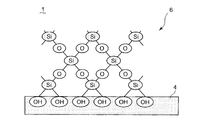
パーヒドロポリシラザンは、−(SiH2NH)−を基本ユニットとして有しており、常温で緻密なシリカ(SiO2)に転化する。例えば、図2に示すように、パーヒドロポリシラザンは、OH基を有する物質と反応して加水分解され、常温でシリカに転化し、伝熱管1の基材面4を被覆する。
−(SiH2NH)− + 2H2O → SiO2 + 2H2
Specifically, the corrosion-
Perhydropolysilazane has — (SiH 2 NH) — as a basic unit, and is converted into dense silica (SiO 2 ) at room temperature. For example, as shown in FIG. 2, perhydropolysilazane reacts with a substance having an OH group to be hydrolyzed, converted to silica at room temperature, and covers the
- (SiH 2 NH) - + 2H 2 O →
なお、耐食層6としてガラス繊維を用いた場合、耐食層6の厚さは、10〜100μmであってもよい。
In addition, when glass fiber is used as the corrosion-
伝熱部2は、ボイラ管1の表面に形成され、ボイラ管1に熱を伝達する。伝熱部2は、図1に示すように、ボイラ管1の表面に突設して複数形成されてもよい。
これにより、ボイラ管1の表面に突設している伝熱部2が耐食層6による伝熱阻害の影響を軽減することができる。
The
Thereby, the
なお、図1には、伝熱部2として、伝熱管2の基材面4に周方向及び長手方向に複数設けられるスタッドを図示している。スタッドの形状は、特に限定されず、略円柱形状であってもよいし、先端部に向かって先細る略円錐形状であってもよい。
また、図示しないが、伝熱部2は伝熱管2の表面に形成されるフィンであってもよい。
FIG. 1 shows a plurality of studs provided in the circumferential direction and the longitudinal direction on the
Although not shown, the
上述のようにして形成される耐食層6および伝熱部2は、ボイラ管1の周方向及び長手方向に多数混在する。また、伝熱部2が耐食層6によって全て覆われないように少なくとも一部露出して設けられることが好ましい。
Many corrosion-
本実施形態のボイラ管の配管構造では、耐食層6と伝熱部2とがボイラ管1の周方向及び長手方向に多数混在しているので、ボイラ管1の耐食とボイラ管1の熱交換率維持を両立することができる。また、従来のNi基材料や金属炭化物を主成分とした材料を用いることなく、表面処理できるのでコストを低減することが可能となる。
In the boiler pipe piping structure of the present embodiment, since the corrosion-
[実施形態2]
次に、実施形態2に係るボイラ管の配管構造について説明する。図3は、実施形態2のボイラ管の配管構造の一例を示す外観図である。
実施形態2では、伝熱部2が異なる点を除けば、実施形態1で説明したボイラ管の配管構造と同一であるので、その詳細な説明を省略する。
[Embodiment 2]
Next, the piping structure of the boiler pipe according to the second embodiment will be described. FIG. 3 is an external view showing an example of the piping structure of the boiler pipe of the second embodiment.
The second embodiment is the same as the piping structure of the boiler pipe described in the first embodiment except that the
伝熱部は、図2に示すように、ボイラ管1の表面に沿って形成されるメッシュ構造8であってもよい。
メッシュ構造8の伝熱部を形成するには、まず、耐食層6を形成するコーティング材がボイラ管1の基材面4に付着しないように、予めボイラ管1の表面に網目状のマスキングを施す。その後、ボイラ管1の表面にマスキングをした状態で、常温硬化可能なガラス繊維などのコーティング材を塗布する。次いで、コーティング材の硬化が始まる前に、マスキングを剥がすことにより、メッシュ構造8の伝熱部である基材面4を露出させることができる。
As shown in FIG. 2, the heat transfer section may be a
In order to form the heat transfer portion of the
上述のようにしてボイラ管1の表面に沿って形成されるメッシュ構造8が耐食層6による伝熱阻害の影響を軽減することができるので、ボイラ管1の耐食とボイラ管1の熱交換率維持を両立することができる。
Since the
1 ボイラ管
2 伝熱部(スタッド)
4 基材面
6 耐食層
8 メッシュ構造
1
4
Claims (4)
前記ボイラ管の表面に形成され、前記ボイラ管に少なくとも耐食性を付与する耐食層と、前記ボイラ管の表面に形成され、前記ボイラ管に熱を伝達する伝熱部とを備え、
前記耐食層と前記伝熱部が前記ボイラ管の周方向及び長手方向に多数混在することを特徴とするボイラ管の配管構造。 In the piping structure of the boiler tube provided in the boiler having the heat exchange part,
Formed on the surface of the boiler pipe, and provided with a corrosion-resistant layer that imparts at least corrosion resistance to the boiler pipe, and a heat transfer section that is formed on the surface of the boiler pipe and transfers heat to the boiler pipe,
A piping structure of a boiler pipe, wherein a large number of the corrosion-resistant layer and the heat transfer section are mixed in a circumferential direction and a longitudinal direction of the boiler pipe.
Priority Applications (1)
| Application Number | Priority Date | Filing Date | Title |
|---|---|---|---|
| JP2010037704A JP2011174635A (en) | 2010-02-23 | 2010-02-23 | Boiler piping structure |
Applications Claiming Priority (1)
| Application Number | Priority Date | Filing Date | Title |
|---|---|---|---|
| JP2010037704A JP2011174635A (en) | 2010-02-23 | 2010-02-23 | Boiler piping structure |
Publications (1)
| Publication Number | Publication Date |
|---|---|
| JP2011174635A true JP2011174635A (en) | 2011-09-08 |
Family
ID=44687658
Family Applications (1)
| Application Number | Title | Priority Date | Filing Date |
|---|---|---|---|
| JP2010037704A Withdrawn JP2011174635A (en) | 2010-02-23 | 2010-02-23 | Boiler piping structure |
Country Status (1)
| Country | Link |
|---|---|
| JP (1) | JP2011174635A (en) |
-
2010
- 2010-02-23 JP JP2010037704A patent/JP2011174635A/en not_active Withdrawn
Similar Documents
| Publication | Publication Date | Title |
|---|---|---|
| JP2007015913A5 (en) | ||
| CN104404430A (en) | Iron-based non-crystalline composite coating for protecting heat exchange pipes in flue gas waste heat recovery system of power station boiler and laser re-melting and moulding technology thereof | |
| JP2007051364A5 (en) | ||
| US20070048537A1 (en) | Coated Metallic Component | |
| CN101636524B (en) | Method of preventing sulfide corrosion, high-temperature member with resistance to sulfide corrosion, and method of repairing heat-transfer tube | |
| CN101375102A (en) | Improvements to the lifespan and performance of Flame Tips | |
| US7204061B2 (en) | Fireproof structure and installation method for protecting water pipes | |
| JP2011174635A (en) | Boiler piping structure | |
| CN104136659B (en) | The surface treatment method of steel coating and heat-transfer pipe | |
| CN103925612A (en) | Method improving smoke corrosion resistance of pipeline on heating surface of coal-fired boiler | |
| JP2011174634A (en) | Surface treatment method of heat transfer tube and structure of heat transfer tube | |
| CN219573294U (en) | High-temperature-resistant and corrosion-resistant thermocouple | |
| JP2002310594A (en) | Heat exchanger with heat exchanger tubes for heat exchange | |
| JP5645534B2 (en) | Heat exchanger for corrosive hot gas | |
| KR101064953B1 (en) | Erosion-prevention coated boiler heat exchanger piping and its coating method | |
| CN219493494U (en) | Organosilicon heat-resistant coating structure for process pipeline | |
| JP3715184B2 (en) | Stave cooler and manufacturing method of double pipe used therefor | |
| JPS60205108A (en) | Protector structure of heat transfer tube | |
| CN223740252U (en) | A corrosion-resistant ductile iron pipe | |
| CN223610123U (en) | High-temperature corrosion-resistant scaling-resistant gradient coating for incinerator | |
| JP3294035B2 (en) | Heat transfer tube wear prevention method for fluidized bed boiler. | |
| CN221501234U (en) | Stainless steel furnace tube and LPCVD equipment | |
| CN203744802U (en) | Enamel heat transfer element | |
| JP2005090833A (en) | Heat exchanger | |
| JP2015183194A (en) | Production method of anticorrosive coating film |
Legal Events
| Date | Code | Title | Description |
|---|---|---|---|
| A300 | Withdrawal of application because of no request for examination |
Free format text: JAPANESE INTERMEDIATE CODE: A300 Effective date: 20130507 |