JP2011145107A - Method and inspection set of detecting air leaking point of air tube of differential distribution type heat sensor - Google Patents
Method and inspection set of detecting air leaking point of air tube of differential distribution type heat sensor Download PDFInfo
- Publication number
- JP2011145107A JP2011145107A JP2010004202A JP2010004202A JP2011145107A JP 2011145107 A JP2011145107 A JP 2011145107A JP 2010004202 A JP2010004202 A JP 2010004202A JP 2010004202 A JP2010004202 A JP 2010004202A JP 2011145107 A JP2011145107 A JP 2011145107A
- Authority
- JP
- Japan
- Prior art keywords
- gas
- air
- pipe
- air pipe
- tube
- Prior art date
- Legal status (The legal status is an assumption and is not a legal conclusion. Google has not performed a legal analysis and makes no representation as to the accuracy of the status listed.)
- Pending
Links
Images


Abstract
Description
本発明は、差動式分布型熱感知器の空気管の漏気箇所を検出する方法及び検査セットに関するものである。更に詳しくは、空気管式の差動式分布型熱感知器の作動試験を行って、空気管に封入されている空気が漏れている場合、その漏気箇所を検出することができる方法及び検査セットに関する。 The present invention relates to a method and a test set for detecting an air leak location of an air pipe of a differential distributed heat sensor. More specifically, when an air tube type differential distributed heat sensor is subjected to an operation test and the air enclosed in the air tube is leaking, a method and an inspection capable of detecting the leak location are detected. Regarding the set.
差動式分布型熱感知器(以下、単に「熱感知器」という場合がある)は、その周囲の温度の上昇率が一定以上になることで火災の発生を感知し、信号や音を発するなどして周りに報知するものである。熱感知器は、空気管式、熱電対式及び熱半導体式に大別され、この中では、故障しにくく性能が安定している空気管式のものが多く採用されている。 A differential distributed heat detector (hereinafter sometimes referred to simply as a “heat detector”) detects the occurrence of a fire and emits a signal or sound when the rate of increase in ambient temperature exceeds a certain level. Etc. to inform the surroundings. The heat detector is roughly classified into an air tube type, a thermocouple type, and a thermal semiconductor type, and among these, an air tube type that is less likely to break down and has stable performance is often used.
熱感知器の空気管は、例えば各種工場や作業所、体育館や文化財などの天井部に数十メートルにわたり張り巡らされており、長期にわたる使用では、雨漏りや各種腐食性ガスの影響あるいは建物の造作工事をなどで劣化又は損傷し、これにより穴が開いてしまうことがあった。この場合は、空気管に封入されている空気が穴から漏れてしまうため、熱感知器が正常に作動しなくなる。 The air pipes of heat detectors are stretched over several tens of meters, for example, on the ceilings of various factories, workshops, gymnasiums, cultural properties, etc. There was a case that a hole was opened due to deterioration or damage of the construction work. In this case, since the air enclosed in the air pipe leaks from the hole, the heat sensor does not operate normally.
したがって、熱感知器の性能を維持するために、定期的に熱感知器の作動試験を行うことが義務付けられている。空気管式の熱感知器の作動試験を行う装置として一例をあげれば、特許文献1に記載された試験装置がある。 Therefore, in order to maintain the performance of the heat sensor, it is obliged to periodically test the operation of the heat sensor. As an example of an apparatus for performing an operation test of an air tube type heat sensor, there is a test apparatus described in Patent Document 1.
この試験装置は、接続部を熱感知器側の接続部に接続し、電動ドライバによって調整ねじを調整室内に所定の速度でねじ込み、圧力注入部から注入口を介して空気管内に空気が注入され、空気管の空気圧は、圧力測定部を介して圧力センサで検出され、制御部では、圧力センサで検出される空気圧が所定の上昇率になるように電動ドライバの速度を制御し、規定時間が経過したときに、熱感知器の火災判定部から火災発生の信号が出力されれば、この熱感知器の動作は正常と判定することによって、差動式分布型の熱感知器を簡単に試験することができるというものである。 In this test apparatus, the connection part is connected to the connection part on the heat sensor side, the adjustment screw is screwed into the adjustment chamber at a predetermined speed by an electric driver, and air is injected from the pressure injection part into the air pipe through the injection port. The air pressure of the air pipe is detected by the pressure sensor via the pressure measuring unit, and the control unit controls the speed of the electric driver so that the air pressure detected by the pressure sensor becomes a predetermined rate of increase, and the specified time If a fire occurrence signal is output from the fire detector of the heat detector when it has passed, the operation of the heat detector is judged normal, and the differential distribution type heat detector can be easily tested. It can be done.
しかしながら、特許文献1に記載された試験装置には、次のような課題があった。
すなわち、前記試験装置を使用すれば、空気管から空気が漏れているかどうかを検出することは可能であるが、空気が漏れていることが分かっても、その箇所を特定することはできない。通常、数十メートルあるいはそれ以上にわたり高所に張り巡らされている空気管のどこから空気が漏れているかを特定する作業は、足場の設置なども含めて大変な手間がかかる困難な作業である。したがって、作動試験で空気管の空気が漏れていることが分かった場合、空気が漏れている箇所(漏気箇所)を特定して修復する作業は行わず、空気管全体の張り替えを行っているのが実情である。
However, the test apparatus described in Patent Document 1 has the following problems.
That is, if the test apparatus is used, it is possible to detect whether or not air is leaking from the air pipe, but even if it is found that air is leaking, the location cannot be specified. Usually, the work of identifying where air is leaking from an air pipe stretched at a high place over several tens of meters or more is a difficult work that requires a lot of labor, including the installation of a scaffold. Therefore, if the air test reveals that air in the air pipe is leaking, the work to identify and repair the air leaking part (the air leaking part) is not performed, and the entire air pipe is replaced. Is the actual situation.
(本発明の目的)
本発明は、空気管式の差動式分布型熱感知器の作動試験を行って、空気管に漏気が認められた場合、その漏気箇所を検出することができる方法及び検査セットを提供することを目的とする。
(Object of the present invention)
The present invention provides a method and an inspection set capable of detecting an air leak location when an air pipe is leaked by performing an operation test of an air pipe type differential distributed heat sensor. The purpose is to do.
前記課題を解決するために本発明が講じた手段は次のとおりである。
(1)本発明は、
差動式分布型熱感知器の空気管に反応ガスを注入し、
ガス検知器を使用して、ガス検知器に反応ガスの反応があるかどうかを、布設されている空気管に沿って検査し、
ガス検知器に反応ガスの反応があった箇所を漏気箇所として特定する、
差動式分布型熱感知器の空気管の漏気箇所を検出する方法である。
Means taken by the present invention to solve the above-mentioned problems are as follows.
(1) The present invention
Inject the reaction gas into the air pipe of the differential distributed heat sensor,
A gas detector is used to check whether there is a reaction of the reaction gas in the gas detector along the installed air pipe,
Identify the location where the reaction of the reaction gas has occurred in the gas detector as the leak location,
This is a method for detecting a leak location of an air pipe of a differential distributed heat sensor.
(2)本発明は、
反応ガスを熱感知器の空気管へ送給するガス送給器と、
反応ガスを検出するガス検知器と、
で構成されており、
前記ガス送給器は、
反応ガス供給手段と、
反応ガス供給手段から供給される反応ガスを差動式分布型熱感知器の空気管へ送るガス送給管と、
前記空気管のガス圧を計測する圧力計と、
を備えている、
差動式分布型熱感知器の空気管の漏気箇所を検出する検査セットである。
(2) The present invention
A gas feeder for feeding the reaction gas to the air pipe of the heat detector;
A gas detector for detecting the reaction gas;
Consists of
The gas feeder is
Reactive gas supply means;
A gas feed pipe for sending the reaction gas supplied from the reaction gas supply means to the air pipe of the differential distributed heat detector;
A pressure gauge for measuring the gas pressure in the air pipe;
With
It is a test set for detecting a leak point of an air pipe of a differential distributed heat sensor.
(3)本発明は、
反応ガスを熱感知器の空気管へ送給するガス送給器と、
反応ガスを検出するガス検知器と、
で構成されており、
前記ガス送給器は、
反応ガス供給手段と、
反応ガス供給手段から反応ガスが注入されるガス注入管と、
ガス注入管に接続されており、それぞれバルブを有する往路管及び復路管と、
熱感知器から接続を外した空気管往路部を前記往路管に接続し、熱感知器から接続を外した空気管復路部を前記復路管に接続する管接続手段と、
前記復路管のガス圧を計測する圧力計と、
を備えている、
差動式分布型熱感知器の空気管の漏気箇所を検出する検査セットである。
(3) The present invention
A gas feeder for feeding the reaction gas to the air pipe of the heat detector;
A gas detector for detecting the reaction gas;
Consists of
The gas feeder is
Reactive gas supply means;
A gas injection pipe into which the reaction gas is injected from the reaction gas supply means;
Connected to the gas injection pipe, each of the forward pipe and the return pipe each having a valve;
A pipe connecting means for connecting an air pipe forward path part disconnected from the heat sensor to the forward pipe, and connecting an air pipe return path part disconnected from the heat sensor to the return pipe;
A pressure gauge for measuring the gas pressure in the return pipe;
With
It is a test set for detecting a leak point of an air pipe of a differential distributed heat sensor.
(4)本発明は、
空気管内に空気を注入して、空気管内の反応ガスを空気と入れ替える空気注入ポンプを備えている、
前記(2)又は(3)の差動式分布型熱感知器の空気管の漏気箇所を検出する検査セットである。
(4) The present invention
It is equipped with an air injection pump that injects air into the air pipe and replaces the reaction gas in the air pipe with air.
It is a test | inspection set which detects the leak location of the air pipe of the differential type | mold distributed heat sensor of said (2) or (3).
特許請求の範囲及び明細書にいう「反応ガス」としては、ガス検知器による検出が確実にできると共に、毒性がなく、環境に対する負荷が小さいガスを採用するのが好ましい。例えば、温室効果ガスではあるが、オゾン層を破壊しにくいとされる代替フロン(ハイドロクロロフルオロカーボン(HCFC)類、あるいはHFC-134aに代表されるハイドロフルオロカーボン(HFC)類など)があげられるが、これに限定されるものではない。 As the “reactive gas” in the claims and specification, it is preferable to employ a gas that can be reliably detected by a gas detector, has no toxicity, and has a low environmental load. For example, alternative fluorocarbons (hydrochlorofluorocarbons (HCFCs) or hydrofluorocarbons (HFCs) typified by HFC-134a), which are greenhouse gases but are less likely to destroy the ozone layer, It is not limited to this.
(作用)
本発明に係る検査セットの作用を説明する。なお、ここでは、説明で使用する各構成要件に、後述する実施の形態において各部に付与した符号を対応させて付与するが、この符号は、特許請求の範囲の各請求項に記載した符号と同様に、あくまで内容の理解を容易にするためであって、各構成要件の意味を前記各部に限定するものではない。
(Function)
The operation of the test set according to the present invention will be described. Here, the constituent elements used in the description are assigned in correspondence with the reference numerals given to the respective parts in the embodiments described later. These reference numerals are the same as the reference numerals described in the claims of the claims. Similarly, it is only for the purpose of facilitating the understanding of the contents, and the meaning of each component is not limited to each of the above parts.
空気管式の差動式分布型熱感知器(4)の作動試験を行って、空気管(46)に漏気が認められた場合は、まず、差動式分布型熱感知器(4)の空気管(46)の往路部(461)と復路部(462)をガス送給器(1)の接続箇所から取り外す。
次に、管接続手段(14)を介して空気管往路部(461)をガス送給器(1)の往路管(12)に接続し、空気管復路部(462)を復路管(13)に接続する。なお、復路管(13)側は、バルブを開ける等して大気に開放しておく。
When an air pipe differential heat detector (4) is tested and air leakage is found in the air pipe (46), the differential heat detector (4) The forward path part (461) and the return path part (462) of the air pipe (46) are removed from the connection point of the gas feeder (1).
Next, the air pipe forward path part (461) is connected to the forward pipe (12) of the gas feeder (1) via the pipe connecting means (14), and the air pipe return path part (462) is connected to the return pipe (13). Connect to. The return pipe (13) side is opened to the atmosphere by opening a valve or the like.
反応ガス供給手段(17)によってガス注入管(10)に反応ガスを所定のガス圧で供給する。復路管(13)側は大気に開放されているので、反応ガスは、ガス送給管である往路管(12)を通り空気管往路部(461)から空気管(46)に入り、空気管(46)内部の空気を押し出して空気と入れ替わる。空気管(46)内部の空気が反応ガスに入れ替わったら、復路管(13)側を閉じてガスが大気に排出されないようにする。復路管(13)終端側のガス圧は、実質的に空気管(46)内部のガス圧として圧力計(15)で計測される。 The reactive gas is supplied to the gas injection pipe (10) at a predetermined gas pressure by the reactive gas supply means (17). Since the return pipe (13) side is open to the atmosphere, the reaction gas passes through the forward pipe (12), which is a gas feed pipe, and enters the air pipe (46) from the air pipe forward section (461). (46) Push out the air inside and replace it with air. When the air in the air pipe (46) is replaced with the reaction gas, the return pipe (13) side is closed to prevent the gas from being discharged into the atmosphere. The gas pressure at the end of the return pipe (13) is substantially measured by the pressure gauge (15) as the gas pressure inside the air pipe (46).
このように、反応ガスを空気管(46)に所定のガス圧で送給することにより、空気管(46)の漏気箇所(460)から反応ガスを漏気させるようにする。
そして、ガス検知器(2)を、建物の天井部等に布設されている空気管(46)に沿って移動させ、ガス検知器(2)に反応ガスの反応があるかどうかを検査する。そして、反応ガスの反応があった箇所を目視で観察し、漏気箇所(460)を特定して修復する。
In this manner, the reaction gas is supplied to the air pipe (46) at a predetermined gas pressure, so that the reaction gas is leaked from the air leakage portion (460) of the air pipe (46).
Then, the gas detector (2) is moved along the air pipe (46) installed on the ceiling or the like of the building, and it is inspected whether or not there is a reaction of the reaction gas in the gas detector (2). Then, the part where the reaction of the reactive gas has been observed visually, and the leaking part (460) is identified and repaired.
漏気箇所(460)の修復後、再度空気管(46)に反応ガスを所定のガス圧で供給して加圧し、減圧がないかどうかを圧力計(15)の表示で確認する。減圧がなければ、漏気していないと判断し、ガス注入管(10)の一端の排気バルブ(18)を開いて排気し、空気管(46)内の残圧を開放して検査を終了する。 After repairing the leaking part (460), the reaction gas is again supplied to the air pipe (46) with a predetermined gas pressure to increase the pressure, and whether or not there is any pressure reduction is confirmed on the display of the pressure gauge (15). If there is no pressure reduction, it is judged that there is no leakage, the exhaust valve (18) at one end of the gas injection pipe (10) is opened and exhausted, the residual pressure in the air pipe (46) is released, and the inspection is completed. To do.
空気管往路部(461)と空気管復路部(462)を管接続手段(14)から取り外し、空気管往路部(461)と空気管復路部(462)のうち、一方側はそのまま外気に開放した状態とし、他方側には空気注入ポンプ(3)を接続する。そして、空気管(46)内部へ空気を送り、反応ガスを空気管(46)から排出して空気と入れ替えた後、空気管往路部(461)と空気管復路部(462)を元のように差動式分布型熱感知器(4)の接続箇所に接続する。 Remove the air pipe forward path part (461) and the air pipe return path part (462) from the pipe connecting means (14), and one side of the air pipe forward path part (461) and the air pipe return path part (462) is opened to the outside as it is. The air injection pump (3) is connected to the other side. Then, air is sent into the air pipe (46), the reaction gas is discharged from the air pipe (46) and replaced with air, and then the air pipe forward path part (461) and the air pipe return path part (462) are restored to the original state. Connect to the connection point of the differential distributed heat sensor (4).
本発明は、空気管式の差動式分布型熱感知器の作動試験を行って、空気管に漏気が認められた場合、その漏気箇所を容易に検出することができる方法及び検査セットを提供することができる。 The present invention relates to a method and an inspection set for performing an operation test of an air tube type differential distributed heat sensor, and in the case where air leak is recognized in the air tube, the leak location can be easily detected. Can be provided.
本発明を図面に示した実施の形態に基づき詳細に説明する。 The present invention will be described in detail based on the embodiments shown in the drawings.
まず、図1を参照し、検査セットAの構成及び構造を説明する。
検査セットAは、空気管式の差動式分布型熱感知器の作動試験を行った際に、空気管に封入されている空気が、空気管の劣化や腐蝕によって開いた穴から漏れている場合、その漏気箇所を検出することができるものである。
First, the configuration and structure of the inspection set A will be described with reference to FIG.
In the inspection set A, when the operation test of the air tube type differential distributed heat sensor is performed, the air enclosed in the air tube leaks from the hole opened due to deterioration or corrosion of the air tube. In this case, the leak location can be detected.
検査セットAは、ガス送給器1(図1(a)に図示)とガス検知器2及び空気注入ポンプ3(いずれも図1(b)に図示)を備えている。
ガス送給器1は、金属製(本実施の形態では真鍮製)のガス注入管10を備えている。ガス注入管10の一端側(図1(a)で左側)には排気バルブ18が設けられ、他端側には接続口100が設けられている。ガス注入管10の接続口100側の端部寄りには、バルブ11が取り付けられている。なお、接続口100には、後述するようにガス管16が接続されている。
The inspection set A includes a gas feeder 1 (shown in FIG. 1A), a
The gas feeder 1 includes a
ガス注入管10の排気バルブ18側の端部には、復路管13が接続されており、この復路管13と前記バルブ11の間には、往路管12が接続されている。復路管13の基部にはバルブ130が取り付けられ、往路管12の基部にはバルブ120が取り付けられている。往路管12と復路管13は、柔軟性を有する合成樹脂製であり、それらの先端は、管接続手段である管接続具14に接続されている。管接続具14の往路管12と復路管13が接続されている側と反対側には、後述する空気管往路部461と空気管復路部462を接続する端子受141、142が設けられている。
A
ガス注入管10の往路管12と復路管13の各接続部の間には閉塞部101が設けられており、通気できないようになっている。そして、ガス注入管10のバルブ130と通じる部分には圧力計15が取り付けられている。これにより、圧力計15は、復路管13終端のガス圧を計測することができる。なお、圧力計15は、実質的に復路管13とつながっている空気管46内部のガス圧を計測するものであり、ガスの加圧用アナライザーである。
A blocking
ガス注入管10の前記接続口100には、合成樹脂製のガス管16の一端が接続されている。ガス管16の他端には、反応ガス供給手段であるガスボンベ17が接続されている。本実施の形態では、反応ガスとして代替フロンであるHFC-134aガスが充填されているガスボンベ17が採用されている。ガスボンベ17から供給されるHFC-134aガスは、ガス注入管10のバルブ11とバルブ120を開けることにより、前記往路管12へ送られる。
One end of a synthetic
ガス検知器2は、前記HFC-134aガスを高感度で検出することができる検知機であり、先端部にガスセンサ20を備えている。ガス検知器2は、通常は天井部等の高所に張り巡らされている空気管46に沿って検出作業ができるように、長尺の柄21の先端に固定されている。
また、空気注入ポンプ3は、ガス送給器1で空気管46の漏気箇所を特定し、その漏気箇所を修復した後に、空気管46内に空気を注入してHFC-134aガスと入れ替えるためのポンプである。なお、空気注入ポンプ3の容量は、例えば数回の注入で入れ替えが済むように適宜設定される。
The
In addition, the
(作用)
図1乃至図5を参照して、本実施の形態に係る検査セットAを使用した漏気箇所の検出方法及び検査セットAの作用を説明する。
まず、図2及び図3を参照して、漏気箇所の検出作業の対象となる空気管式の差動式分布型熱感知器4の構造及び作動試験の概略を説明する。
(Function)
With reference to FIG. 1 thru | or FIG. 5, the detection method of the leak location using the test | inspection set A which concerns on this Embodiment, and the effect | action of the test | inspection set A are demonstrated.
First, with reference to FIG.2 and FIG.3, the outline of the structure and operation test of the air pipe type differential distributed heat sensor 4 used as the object of the detection work of a leak location are demonstrated.
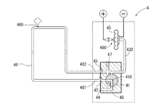
差動式分布型熱感知器4は、コックスタンド40を有し、コックスタンド40には、切替コック41が回転操作自在に収められている。コックスタンド40は、建築物の天井等に張り巡らされる空気管46の空気管往路部461を接続する往路流路孔42と、空気管復路部462を接続する復路流路孔43及び試験孔44が形成されている。空気管46は銅製の細管であり、その外表面は合成樹脂製の被膜で被覆されている。
The differential distributed heat sensor 4 includes a
切替コック41には、所定形状の制御流路410が形成されている。往路流路孔42は、切替コック41の制御流路410につながっている。復路流路孔43は、一方で連通管430を介してダイヤフラム45につながり、また一方で切替コック41の制御流路410につながるようになっている。復路流路孔43につながっているリーク孔47は、空気管46内の空気の日常の気温変化などによる膨張収縮を打ち消すためのものである。
また、試験孔44は、差動式分布型熱感知器4の作動試験を行う際に切替コック41の制御流路410につながり、空気管46に試験空気を注入する注入管(図示省略)を接続するものである。
A
The
差動式分布型熱感知器4は、図2に示した状態が、火災の発生を監視している監視状態であり、空気管46からダイヤフラム45に至る流路内は、前記リーク孔47を除き密封状態である。この状態で、火災が発生して空気管46内の空気が急激に膨張すると、リーク孔47からの調整排気が間に合わず、ダイヤフラム45が内部の空気の圧力によって変形し、電気的接点450が接触して通電され、これにより報知動作が行われる。
In the differential distributed heat sensor 4, the state shown in FIG. 2 is a monitoring state in which the occurrence of a fire is monitored. In the flow path from the
また、図3に示した状態は、差動式分布型熱感知器4の作動試験を行うときのものである。すなわち、切替コック41がハンドル等(図示省略)によって矢印方向に回転操作されており、往路流路孔42と試験孔44が切替コック41の制御流路410を介し連通している。また、復路流路孔43は、切替コック41の制御流路410にはつながっておらず、ダイヤフラム45のみにつながっている。
Further, the state shown in FIG. 3 is the one when an operation test of the differential distributed heat sensor 4 is performed. That is, the switching
この状態で試験孔44に注入管を接続し、空気管46内部に規定量の試験空気を注入する。空気管46を含む流路に漏気がなければ、ダイヤフラム45が内部の空気の圧力によって変形し、電気的接点450が接触して通電され、これにより報知動作が行われる。しかし、空気管46を含む流路に漏気がある場合は、ダイヤフラム45の内部の空気圧が十分に上がらない。このため、ダイヤフラム45が変形せず、電気的接点450が接触しないので、報知動作は行われない。
In this state, an injection tube is connected to the
このように、空気管46内部に試験空気を注入しても正常に作動しなかった場合は、まず、空気管46の経年劣化等に起因する穴開きによる漏気が疑われる。この漏気箇所を検出する作業を、検査セットAを使用して行う。検査セットAの使用方法及び作用は次のとおりである。
As described above, when the test air is not normally operated even when the test air is injected into the
図1及び図4、図5を参照する。
(1)空気管46の空気管往路部461と空気管復路部462を往路流路孔42と復路流路孔43から取り外し、空気管往路部461をガス送給器1の管接続具14の端子受141に接続し、空気管復路部462を端子受142に接続する(図4参照)。
Please refer to FIG. 1, FIG. 4, and FIG.
(1) The air pipe
(2)ガスボンベ17のバルブ(符号省略)を開け、ガス注入管10のバルブ11、120、130及び排気バルブ18を開けて、反応ガス(HFC-134a)を往路管12へ送る。反応ガスは、往路管12を通り空気管往路部461から空気管46に入り、空気管46内部の空気を押し出して空気と入れ替わる。空気管46内部の空気が反応ガスに入れ替わったら、排気バルブ18を閉じる。そして、復路管13終端側のガス圧(実質的に空気管46内部のガス圧)は、圧力計15で計測される。本実施の形態では、ガス圧を0.3MPaに加圧し、空気管46の漏気箇所460から反応ガスを漏気させるようにする。
(2) The valve (reference number omitted) of the
(3)ガス検知器2を、建物の天井部等に布設されている空気管46に沿って移動させ、ガス検知器2に反応ガスの反応があるかどうかを検査する。この検査は、空気管46の全長にわたり行うようにする。そして、反応ガスの反応があった箇所を目視で観察し、漏気箇所460を特定し、金属管等のスリーブ463で修復する。
(3) The
(4)空気管46の漏気箇所460の修復後、再度空気管46に前記と同様に反応ガスを供給して0.3MPaに加圧し、減圧がないかどうかを圧力計15の表示で確認する。減圧がなければ、漏気していないと判断し、ガス注入管10の排気バルブ18を開いて排気し、空気管46内の残圧を開放して検査を終了する。
(4) After repairing the leaking
(5)空気管往路部461と空気管復路部462を管接続具14の端子受141、142から取り外し、空気管往路部461は往路流路孔42に接続し、空気管復路部462はそのまま外気に開放した状態にする。そして、試験孔44にチューブを介し空気注入ポンプ3を接続し、空気管46内部へ空気を送り、反応ガスを空気管復路部462から外気へ排出して、空気管46内部のガスを空気と入れ替える。なお、この入れ替え作業は、空気注入ポンプ3ではなく、他の手段で空気を送って行うこともできる。
(5) The air pipe
(6)最後に、空気管復路部462を復路流路孔43に接続し、切替コック41を回転操作して元に戻し、試験孔44から空気注入ポンプ3を取り外して、図2に示す監視状態とする。
(6) Finally, the air
このように、本実施の形態に係る検査セットAによれば、差動式分布型熱感知器4の空気管46に漏気がある場合、その漏気箇所460を簡単に検出することができるので、漏気箇所460の修復をすることによって、差動式分布型熱感知器4を正常に作動させることができるようになる。したがって、必ずしも従来のような空気管46全体の張り替えをする必要がなく、メンテナンスを行う際の作業時間や手間あるいは費用を削減する上できわめて有用である。
As described above, according to the inspection set A according to the present embodiment, when there is a leak in the
なお、本明細書で使用している用語と表現は、あくまでも説明上のものであって、なんら限定的なものではなく、本明細書に記述された特徴およびその一部と等価の用語や表現を除外する意図はない。また、本発明の技術思想の範囲内で、種々の変形態様が可能であるということは言うまでもない。 Note that the terms and expressions used in this specification are merely explanatory and are not limiting at all, and terms and expressions equivalent to the features described in this specification and parts thereof. There is no intention to exclude. It goes without saying that various modifications are possible within the scope of the technical idea of the present invention.
A 検査セット
1 ガス送給器
10 ガス注入管
100 接続口
101 閉塞部
11 バルブ
12 往路管
120 バルブ
13 復路管
130 バルブ
14 管接続具
141 端子受
142 端子受
15 圧力計
16 ガス管
17 ガスボンベ
18 排気バルブ
2 ガス検知器
20 ガスセンサ
21 柄
3 空気注入ポンプ
4 差動式分布型熱感知器
40 コックスタンド
41 切替コック
410 制御流路
42 往路流路孔
43 復路流路孔
430 連通管
44 試験孔
45 ダイヤフラム
450 電気的接点
46 空気管
460 漏気箇所
461 空気管往路部
462 空気管復路部
463 スリーブ
47 リーク孔
A Inspection set 1
Claims (4)
ガス検知器(2)を使用して、ガス検知器(2)に反応ガスの反応があるかどうかを、布設されている空気管(46)に沿って検査し、
ガス検知器(2)に反応ガスの反応があった箇所を漏気箇所として特定する、
差動式分布型熱感知器の空気管の漏気箇所を検出する方法。 Inject reaction gas into the air pipe (46) of the differential distributed heat sensor,
Using the gas detector (2), check whether the gas detector (2) has a reaction of the reactive gas along the installed air pipe (46),
Identify the location where the reaction of the reaction gas has occurred in the gas detector (2) as the leak location,
A method of detecting a leak location of an air pipe of a differential distributed heat sensor.
反応ガスを検出するガス検知器(2)と、
で構成されており、
前記ガス送給器(1)は、
反応ガス供給手段(17)と、
反応ガス供給手段(17)から供給される反応ガスを差動式分布型熱感知器の空気管(46)へ送るガス送給管(12)と、
前記空気管(46)のガス圧を計測する圧力計(15)と、
を備えている、
差動式分布型熱感知器の空気管の漏気箇所を検出する検査セット。 A gas feeder (1) for feeding the reaction gas to the air pipe (46) of the heat detector;
A gas detector (2) for detecting the reaction gas;
Consists of
The gas feeder (1)
Reactive gas supply means (17);
A gas supply pipe (12) for sending the reaction gas supplied from the reaction gas supply means (17) to the air pipe (46) of the differential distributed heat detector;
A pressure gauge (15) for measuring the gas pressure of the air pipe (46);
With
An inspection set that detects the leak location of the air pipe of a differential distributed heat sensor.
反応ガスを検出するガス検知器(2)と、
で構成されており、
前記ガス送給器(1)は、
反応ガス供給手段(17)と、
反応ガス供給手段(17)から反応ガスが注入されるガス注入管(10)と、
ガス注入管(10)に接続されており、それぞれバルブ(120,130)を有する往路管(12)及び復路管(13)と、
熱感知器から接続を外した空気管往路部(461)を前記往路管(12)に接続し、熱感知器から接続を外した空気管復路部(462)を前記復路管(13)に接続する管接続手段(14)と、
前記復路管(13)のガス圧を計測する圧力計(15)と、
を備えている、
差動式分布型熱感知器の空気管の漏気箇所を検出する検査セット。 A gas feeder (1) for feeding the reaction gas to the air pipe (46) of the heat detector;
A gas detector (2) for detecting the reaction gas;
Consists of
The gas feeder (1)
Reactive gas supply means (17);
A gas injection pipe (10) into which reaction gas is injected from the reaction gas supply means (17);
An outward pipe (12) and a return pipe (13) each having a valve (120, 130) connected to the gas injection pipe (10);
The air pipe forward path part (461) disconnected from the heat sensor is connected to the forward path pipe (12), and the air pipe return path part (462) disconnected from the heat sensor is connected to the return pipe (13). A pipe connecting means (14) for
A pressure gauge (15) for measuring the gas pressure in the return pipe (13);
With
An inspection set that detects the leak location of the air pipe of a differential distributed heat sensor.
請求項2又は3の何れか一項に記載の差動式分布型熱感知器の空気管の漏気箇所を検出する検査セット。 An air injection pump (3) for injecting air into the air pipe (46) and replacing the reaction gas in the air pipe (46) with air;
The test | inspection set which detects the leak location of the air pipe of the differential type | mold distributed heat sensor as described in any one of Claim 2 or 3.
Priority Applications (1)
| Application Number | Priority Date | Filing Date | Title |
|---|---|---|---|
| JP2010004202A JP2011145107A (en) | 2010-01-12 | 2010-01-12 | Method and inspection set of detecting air leaking point of air tube of differential distribution type heat sensor |
Applications Claiming Priority (1)
| Application Number | Priority Date | Filing Date | Title |
|---|---|---|---|
| JP2010004202A JP2011145107A (en) | 2010-01-12 | 2010-01-12 | Method and inspection set of detecting air leaking point of air tube of differential distribution type heat sensor |
Publications (1)
| Publication Number | Publication Date |
|---|---|
| JP2011145107A true JP2011145107A (en) | 2011-07-28 |
Family
ID=44460104
Family Applications (1)
| Application Number | Title | Priority Date | Filing Date |
|---|---|---|---|
| JP2010004202A Pending JP2011145107A (en) | 2010-01-12 | 2010-01-12 | Method and inspection set of detecting air leaking point of air tube of differential distribution type heat sensor |
Country Status (1)
| Country | Link |
|---|---|
| JP (1) | JP2011145107A (en) |
Cited By (2)
| Publication number | Priority date | Publication date | Assignee | Title |
|---|---|---|---|---|
| CN102384825A (en) * | 2011-11-09 | 2012-03-21 | 福建海洋铜业有限公司 | Air tightness detection device for gate valve |
| JP2018004292A (en) * | 2016-06-28 | 2018-01-11 | 有限会社石澤モータース | Method for detecting leakage of refrigerant of automobile air conditioner |
-
2010
- 2010-01-12 JP JP2010004202A patent/JP2011145107A/en active Pending
Cited By (2)
| Publication number | Priority date | Publication date | Assignee | Title |
|---|---|---|---|---|
| CN102384825A (en) * | 2011-11-09 | 2012-03-21 | 福建海洋铜业有限公司 | Air tightness detection device for gate valve |
| JP2018004292A (en) * | 2016-06-28 | 2018-01-11 | 有限会社石澤モータース | Method for detecting leakage of refrigerant of automobile air conditioner |
Similar Documents
| Publication | Publication Date | Title |
|---|---|---|
| EP2831557B1 (en) | Leak location detection system | |
| WO2017104643A1 (en) | Leakage inspection device and method | |
| CN105067190B (en) | A kind of coal dust transmission pipeline leakage early warning detection method | |
| JP2012052531A (en) | Detection and measuring method, and device | |
| JP6541584B2 (en) | How to inspect a gas supply system | |
| JP2012047651A (en) | Leak detector | |
| Bergoglio et al. | Leak rate metrology for the society and industry | |
| JP2011145107A (en) | Method and inspection set of detecting air leaking point of air tube of differential distribution type heat sensor | |
| KR100832345B1 (en) | Leak rate and life cycles test system of pneumatic angle valve for vacuum | |
| JP2006177810A (en) | Inspection device and inspection method | |
| JP2009276309A (en) | Leak detector | |
| JP2007327849A (en) | Leak inspection method and leak inspection system | |
| US8587319B1 (en) | Battery operated flame ionization detector | |
| US20240009497A1 (en) | Monitoring and extinguishing device | |
| KR101422506B1 (en) | Apparatus for testing flange leakages, and a method for testing flange leakages using the same | |
| KR200489626Y1 (en) | Piping connector and inspection device | |
| US11326978B2 (en) | Leak indicating clamp | |
| KR20080073518A (en) | Semiconductor manufacturing equipment and method for detecting leak | |
| JP5354919B2 (en) | Air piping leak location judgment method | |
| US11359748B2 (en) | Connection system between a distribution member and a receiving member and leak detection method | |
| CN208187667U (en) | The device of the pressure application leak detection and Data correction of elemental analyser gas piping | |
| KR20120063238A (en) | Particle measuring apparatus | |
| JP4448536B2 (en) | Glass dough leak detection method and apparatus for glass melting kiln | |
| KR20100022907A (en) | Leakage detector for pipe | |
| CN112903206A (en) | Air tightness detection system and air tightness detection method |