JP2011140902A - Control device of internal combustion engine - Google Patents
Control device of internal combustion engine Download PDFInfo
- Publication number
- JP2011140902A JP2011140902A JP2010001926A JP2010001926A JP2011140902A JP 2011140902 A JP2011140902 A JP 2011140902A JP 2010001926 A JP2010001926 A JP 2010001926A JP 2010001926 A JP2010001926 A JP 2010001926A JP 2011140902 A JP2011140902 A JP 2011140902A
- Authority
- JP
- Japan
- Prior art keywords
- egr
- internal combustion
- combustion engine
- fuel
- passage
- Prior art date
- Legal status (The legal status is an assumption and is not a legal conclusion. Google has not performed a legal analysis and makes no representation as to the accuracy of the status listed.)
- Withdrawn
Links
Images


Classifications
-
- F—MECHANICAL ENGINEERING; LIGHTING; HEATING; WEAPONS; BLASTING
- F02—COMBUSTION ENGINES; HOT-GAS OR COMBUSTION-PRODUCT ENGINE PLANTS
- F02D—CONTROLLING COMBUSTION ENGINES
- F02D41/00—Electrical control of supply of combustible mixture or its constituents
- F02D41/30—Controlling fuel injection
- F02D41/3094—Controlling fuel injection the fuel injection being effected by at least two different injectors, e.g. one in the intake manifold and one in the cylinder
-
- F—MECHANICAL ENGINEERING; LIGHTING; HEATING; WEAPONS; BLASTING
- F02—COMBUSTION ENGINES; HOT-GAS OR COMBUSTION-PRODUCT ENGINE PLANTS
- F02D—CONTROLLING COMBUSTION ENGINES
- F02D41/00—Electrical control of supply of combustible mixture or its constituents
- F02D41/0025—Controlling engines characterised by use of non-liquid fuels, pluralities of fuels, or non-fuel substances added to the combustible mixtures
- F02D41/0047—Controlling exhaust gas recirculation [EGR]
- F02D41/005—Controlling exhaust gas recirculation [EGR] according to engine operating conditions
-
- F—MECHANICAL ENGINEERING; LIGHTING; HEATING; WEAPONS; BLASTING
- F02—COMBUSTION ENGINES; HOT-GAS OR COMBUSTION-PRODUCT ENGINE PLANTS
- F02D—CONTROLLING COMBUSTION ENGINES
- F02D41/00—Electrical control of supply of combustible mixture or its constituents
- F02D41/0025—Controlling engines characterised by use of non-liquid fuels, pluralities of fuels, or non-fuel substances added to the combustible mixtures
- F02D41/0047—Controlling exhaust gas recirculation [EGR]
- F02D41/0065—Specific aspects of external EGR control
-
- F—MECHANICAL ENGINEERING; LIGHTING; HEATING; WEAPONS; BLASTING
- F02—COMBUSTION ENGINES; HOT-GAS OR COMBUSTION-PRODUCT ENGINE PLANTS
- F02D—CONTROLLING COMBUSTION ENGINES
- F02D41/00—Electrical control of supply of combustible mixture or its constituents
- F02D41/02—Circuit arrangements for generating control signals
- F02D41/04—Introducing corrections for particular operating conditions
- F02D41/06—Introducing corrections for particular operating conditions for engine starting or warming up
-
- Y—GENERAL TAGGING OF NEW TECHNOLOGICAL DEVELOPMENTS; GENERAL TAGGING OF CROSS-SECTIONAL TECHNOLOGIES SPANNING OVER SEVERAL SECTIONS OF THE IPC; TECHNICAL SUBJECTS COVERED BY FORMER USPC CROSS-REFERENCE ART COLLECTIONS [XRACs] AND DIGESTS
- Y02—TECHNOLOGIES OR APPLICATIONS FOR MITIGATION OR ADAPTATION AGAINST CLIMATE CHANGE
- Y02T—CLIMATE CHANGE MITIGATION TECHNOLOGIES RELATED TO TRANSPORTATION
- Y02T10/00—Road transport of goods or passengers
- Y02T10/10—Internal combustion engine [ICE] based vehicles
- Y02T10/40—Engine management systems
Abstract
Description
本発明は、内燃機関の制御装置に関する。 The present invention relates to a control device for an internal combustion engine.
吸気ポート内に燃料を噴射するポート噴射用インジェクタと、燃焼室内に燃料を直接噴射する筒内噴射用インジェクタと、を備え、ポート噴射用インジェクタから吸気ポート内に燃料を噴射させて均質燃焼運転を実行する際に、筒内噴射用インジェクタから所定量の燃料を噴射させる技術が知られている(例えば、特許文献1参照。)。この技術によれば、均質燃焼運転の実行中に何らかの理由によって排気還流手段による排気還流量が目標量から外れたとしても、筒内噴射用インジェクタから噴射された燃料が燃焼室内で点火されて燃焼するので、燃焼室内の燃焼状態を安定化させて失火を抑制することができる。 A port injection injector that injects fuel into the intake port and an in-cylinder injector that directly injects fuel into the combustion chamber. The fuel is injected from the port injector into the intake port for homogeneous combustion operation. A technique for injecting a predetermined amount of fuel from an in-cylinder injector during execution is known (see, for example, Patent Document 1). According to this technique, even if the exhaust gas recirculation amount by the exhaust gas recirculation means deviates from the target amount for some reason during execution of the homogeneous combustion operation, the fuel injected from the in-cylinder injector is ignited in the combustion chamber and burned. Therefore, it is possible to stabilize the combustion state in the combustion chamber and suppress misfire.
ところで、高負荷側に内燃機関の動作線を設定して熱効率の高い領域で運転を行なうシステムにおいては、主に冷却損失とノッキングの発生による排気損失とにより熱効率が低下し得る。この熱効率の低下を抑制するために、比較的多くの冷却されたEGRガスを供給して気筒内の熱容量を上げることが行われている。このEGRガスにより、気筒内の温度が低くなるので、冷却損失及びノッキングの発生を抑制できるため、燃費を向上させることができる。 By the way, in a system in which an operation line of the internal combustion engine is set on the high load side and the operation is performed in a region with high thermal efficiency, the thermal efficiency can be lowered mainly due to cooling loss and exhaust loss due to occurrence of knocking. In order to suppress this decrease in thermal efficiency, a relatively large amount of cooled EGR gas is supplied to increase the heat capacity in the cylinder. Since the EGR gas lowers the temperature in the cylinder, the occurrence of cooling loss and knocking can be suppressed, and the fuel efficiency can be improved.
しかし、EGRガスを多く供給すると、EGRガス自体は不活性ガスであるため、燃焼状態が悪化する虞があるので、例えばタンブル比を高くして気筒内の乱れを大きくしたり、圧縮比を高くしたりして燃焼状態の悪化を抑制している。このようなシステムでは、EGRガスを多く供給するときには燃焼状態の悪化を抑制できるが、何らかの原因によりEGRガスを多く供給することができなくなったときには、EGRガスによるノッキング抑制の効果を得ることができないため、ノッキングが発生し易くなる。そうすると、車両サージを起こす虞がある。特に、加速運転時には、EGRガスが遅れて供給されるため、すぐには目標量を確保することができないので、ノッキングが発生し易くなる。 However, if a large amount of EGR gas is supplied, since the EGR gas itself is an inert gas, the combustion state may be deteriorated. For example, the turbulence in the cylinder is increased by increasing the tumble ratio, or the compression ratio is increased. To suppress the deterioration of the combustion state. In such a system, when a large amount of EGR gas is supplied, deterioration of the combustion state can be suppressed, but when a large amount of EGR gas cannot be supplied for some reason, the effect of suppressing knocking by the EGR gas cannot be obtained. Therefore, knocking is likely to occur. Then, there is a risk of causing a vehicle surge. In particular, during the acceleration operation, since the EGR gas is supplied with a delay, the target amount cannot be secured immediately, so that knocking is likely to occur.
本発明は、上記したような問題点に鑑みてなされたものであり、その目的は、内燃機関の吸気通路内と気筒内との燃料噴射量の比率を最適化することによりノッキングの発生を抑制することにある。 The present invention has been made in view of the above-described problems, and its object is to suppress the occurrence of knocking by optimizing the ratio of the fuel injection amount in the intake passage and the cylinder of the internal combustion engine. There is to do.
上記課題を達成するために本発明による内燃機関の制御装置は、以下の手段を採用した。すなわち、本発明による内燃機関の制御装置は、
内燃機関の吸気通路に燃料を噴射する通路内噴射弁と、
前記内燃機関の気筒内に燃料を噴射する筒内噴射弁と、
前記内燃機関の排気通路と吸気通路とを接続し排気の一部をEGRガスとして吸気通路へ供給するEGR装置と、
EGRガス量が目標量に対して不足する過渡運転時においては、定常運転時よりも全燃
料噴射量に対する前記筒内噴射弁からの燃料噴射量の比率を高め、且つ、高めた後の全燃料噴射量に対する前記筒内噴射弁からの燃料噴射量の比率及び気筒内の全ガス量に対するEGRガス量の比率に基づいて点火時期を設定する過渡時制御手段と、
を備えることを特徴とする。
In order to achieve the above object, an internal combustion engine control apparatus according to the present invention employs the following means. That is, the control device for an internal combustion engine according to the present invention provides:
An in-passage injection valve for injecting fuel into the intake passage of the internal combustion engine;
An in-cylinder injection valve for injecting fuel into the cylinder of the internal combustion engine;
An EGR device that connects an exhaust passage and an intake passage of the internal combustion engine and supplies a part of the exhaust gas as EGR gas to the intake passage;
At the time of transient operation where the EGR gas amount is insufficient with respect to the target amount, the ratio of the fuel injection amount from the in-cylinder injection valve to the total fuel injection amount is increased compared to that during steady operation, and the total fuel after the increase Transient control means for setting the ignition timing based on the ratio of the fuel injection amount from the in-cylinder injection valve to the injection amount and the ratio of the EGR gas amount to the total gas amount in the cylinder;
It is characterized by providing.
全燃料噴射量とは、通路内噴射弁からの燃料噴射量と筒内噴射弁からの燃料噴射量とを合わせた燃料噴射量である。そして定常運転時の全燃料噴射量、通路内噴射弁からの燃料噴射量、筒内噴射弁からの燃料噴射量は、例えば内燃機関の運転状態により決定される。この関係は、予め記憶しておくことができる。一方、EGRガス量が目標量に対して不足する過渡運転時においては、定常運転時よりも、全燃料噴射量に対する筒内噴射弁からの燃料噴射量の比率を高くする。この場合、全燃料噴射量は定常運転時と同じにすることができる。つまり、定常運転時よりも、全燃料噴射量に対する筒内噴射弁からの燃料噴射量の比率を高くし、通路内噴射弁からの燃料噴射量の比率を低くする。なお、全燃料噴射量は変更しても良い。例えばタンブル比及び圧縮比が共に高い内燃機関において、加速運転時等でEGRガスが遅れて供給される場合であっても、筒内噴射弁からの燃料噴射量の割合を高くするために、気筒内の温度上昇を燃料の気化潜熱により抑制することができる。これにより、ノッキングの発生を抑制することができる。 The total fuel injection amount is a fuel injection amount obtained by combining the fuel injection amount from the in-passage injection valve and the fuel injection amount from the in-cylinder injection valve. The total fuel injection amount during steady operation, the fuel injection amount from the in-passage injection valve, and the fuel injection amount from the in-cylinder injection valve are determined by, for example, the operating state of the internal combustion engine. This relationship can be stored in advance. On the other hand, in the transient operation where the EGR gas amount is insufficient with respect to the target amount, the ratio of the fuel injection amount from the in-cylinder injection valve to the total fuel injection amount is made higher than in the steady operation. In this case, the total fuel injection amount can be made the same as during steady operation. That is, the ratio of the fuel injection amount from the in-cylinder injection valve to the total fuel injection amount is made higher and the ratio of the fuel injection amount from the in-passage injection valve is made lower than during steady operation. Note that the total fuel injection amount may be changed. For example, in an internal combustion engine having both a high tumble ratio and a high compression ratio, in order to increase the ratio of the fuel injection amount from the in-cylinder injection valve even when EGR gas is supplied with a delay during acceleration operation or the like, The internal temperature rise can be suppressed by the latent heat of vaporization of the fuel. Thereby, occurrence of knocking can be suppressed.
また、EGRガス量が目標量に対して不足する過渡運転時における点火時期を、高めた後の全燃料噴射量に対する筒内噴射弁からの燃料噴射量の比率及び気筒内の全ガス量に対するEGRガス量の比率に基づいて設定することにより、車両サージの限界を超えないように点火時期を設定することができる。ここで、EGR率は、気筒内の全ガス量に対するEGRガス量の比率である。過渡運転時において、全燃料噴射量に対する筒内噴射弁からの燃料噴射量の比率を高くすることで、ノッキングが発生し難くなるため、その分は点火時期を進角させることができる。しかし、EGRガス量が目標量に対して不足しているため、ノッキングが発生し易くなるので、その分は点火時期を遅角させなくてはならない。すなわち、全燃料噴射量に対する筒内噴射弁からの燃料噴射量及びEGR率はノッキングの発生に対して影響を与えるため、これらの値に基づいて点火時期を設定すれば、ノッキングの発生を抑制する点火時期を設定することができる。 Further, the ratio of the fuel injection amount from the in-cylinder injection valve to the total fuel injection amount after increasing the ignition timing in the transient operation where the EGR gas amount is insufficient with respect to the target amount, and the EGR with respect to the total gas amount in the cylinder By setting based on the ratio of the gas amount, the ignition timing can be set so as not to exceed the limit of the vehicle surge. Here, the EGR rate is a ratio of the EGR gas amount to the total gas amount in the cylinder. During transient operation, by increasing the ratio of the fuel injection amount from the in-cylinder injection valve to the total fuel injection amount, knocking is less likely to occur, so that the ignition timing can be advanced by that amount. However, since the EGR gas amount is insufficient with respect to the target amount, knocking is likely to occur. Therefore, the ignition timing must be retarded accordingly. That is, the fuel injection amount from the in-cylinder injection valve and the EGR rate with respect to the total fuel injection amount affect the occurrence of knocking. Therefore, if the ignition timing is set based on these values, the occurrence of knocking is suppressed. Ignition timing can be set.
また、上記課題を達成するために本発明による内燃機関の制御装置は、以下の手段を採用した。すなわち、本発明による内燃機関の制御装置は、
内燃機関の吸気通路に燃料を噴射する通路内噴射弁と、
前記内燃機関の気筒内に燃料を噴射する筒内噴射弁と、
前記内燃機関の排気通路と吸気通路とを接続し排気の一部をEGRガスとして吸気通路へ供給するEGR装置と、
前記内燃機関の温度を検知する検知手段と、
前記検知手段により検知される内燃機関の温度が所定値以下のときに、前記EGR装置によるEGRガスの供給を停止させる停止手段と、
前記停止手段によりEGRガスの供給が停止されている間は、前記通路内噴射弁からの燃料の噴射を停止させて前記筒内噴射弁のみから燃料を噴射させるEGR停止時制御手段と、
を備えることを特徴とする。
In order to achieve the above object, the control device for an internal combustion engine according to the present invention employs the following means. That is, the control device for an internal combustion engine according to the present invention provides:
An in-passage injection valve for injecting fuel into the intake passage of the internal combustion engine;
An in-cylinder injection valve for injecting fuel into the cylinder of the internal combustion engine;
An EGR device that connects an exhaust passage and an intake passage of the internal combustion engine and supplies a part of the exhaust gas as EGR gas to the intake passage;
Detecting means for detecting the temperature of the internal combustion engine;
Stop means for stopping supply of EGR gas by the EGR device when the temperature of the internal combustion engine detected by the detection means is equal to or lower than a predetermined value;
EGR stop time control means for stopping fuel injection from the in-passage injection valve and injecting fuel only from the in-cylinder injection valve while the supply of EGR gas is stopped by the stop means;
It is characterized by providing.
内燃機関の温度とは、例えば冷却水温度、潤滑油温度としても良い。この内燃機関の温度は、気筒内の燃焼状態に影響を与える箇所、部材、または熱媒体の温度とすることができる。そして、内燃機関の温度の所定値とは、EGRガスを供給したときに燃焼状態が悪化する虞のある温度(例えば、燃焼変動が許容範囲を超える温度)であり、例えば内燃機関の暖機が完了する前の温度である。つまり、内燃機関の温度が所定値以下のときにEGRガスを供給すると、燃焼状態が悪化し得る。すなわち、内燃機関の温度が所定値以下の
ときにEGRガスの供給を停止させることにより、燃焼状態の悪化を抑制できる。
The temperature of the internal combustion engine may be, for example, a cooling water temperature or a lubricating oil temperature. The temperature of the internal combustion engine can be the temperature of a location, member, or heat medium that affects the combustion state in the cylinder. The predetermined value of the temperature of the internal combustion engine is a temperature at which the combustion state may be deteriorated when the EGR gas is supplied (for example, a temperature at which the combustion fluctuation exceeds an allowable range). The temperature before completion. That is, if EGR gas is supplied when the temperature of the internal combustion engine is equal to or lower than a predetermined value, the combustion state can be deteriorated. That is, the deterioration of the combustion state can be suppressed by stopping the supply of EGR gas when the temperature of the internal combustion engine is equal to or lower than a predetermined value.
そして、内燃機関の温度が所定値以下のときに筒内噴射弁のみから燃料を噴射させると、気筒内の温度を燃料の気化潜熱により低減することができる。つまり、EGRガスの供給を停止させることによりノッキングが発生し易くなるが、筒内噴射弁のみから燃料を供給することで気筒内の温度を低下させてノッキングの発生を抑制することができる。 When the fuel is injected only from the in-cylinder injection valve when the temperature of the internal combustion engine is equal to or lower than the predetermined value, the temperature in the cylinder can be reduced by the latent heat of vaporization of the fuel. That is, knocking is likely to occur by stopping the supply of EGR gas, but by supplying fuel only from the in-cylinder injection valve, the temperature in the cylinder can be lowered to suppress the occurrence of knocking.
なお、本発明においては、前記過渡時制御手段は、前記過渡運転時における目標EGR率と実際のEGR率とを比較した値に基づいて、全燃料噴射量に対する前記筒内噴射弁からの燃料噴射量の比率を設定することができる。 In the present invention, the transient control means is configured to inject fuel from the in-cylinder injection valve with respect to the total fuel injection amount based on a value obtained by comparing the target EGR rate and the actual EGR rate during the transient operation. The ratio of the quantity can be set.
ここで、比較値は、比であっても良く、差であっても良い。この比較値は、目標EGR率に対して実際のEGR率がどの程度不足しているのかを示す値である。目標EGR率に対して実際のEGR率が小さい場合には、EGRガスが不足しているために、ノッキングが発生し易くなる。これに対し、過渡運転時における目標EGR率と実際のEGR率とを比較した値に基づいて筒内噴射弁からの燃料噴射量の比率を設定すれば、ノッキングの発生のし易さに応じた設定が可能となる。なお、目標EGR率は、例えば内燃機関の運転状態に応じて予め記憶されている値とし、実際のEGR率は、例えば内燃機関の運転状態から推定しても、また実際に測定しても良い。また、EGR率に代えて、EGRガス量、またはEGRガス量を調節するEGR弁の開度の比較値によっても、全燃料噴射量に対する筒内噴射弁からの燃料噴射量の比率を設定することができる。 Here, the comparison value may be a ratio or a difference. This comparison value is a value indicating how much the actual EGR rate is insufficient with respect to the target EGR rate. When the actual EGR rate is smaller than the target EGR rate, knocking is likely to occur because the EGR gas is insufficient. On the other hand, if the ratio of the fuel injection amount from the in-cylinder injection valve is set based on a value obtained by comparing the target EGR rate and the actual EGR rate during the transient operation, it corresponds to the ease of occurrence of knocking. Setting is possible. The target EGR rate may be a value stored in advance according to, for example, the operating state of the internal combustion engine, and the actual EGR rate may be estimated from, for example, the operating state of the internal combustion engine, or may be actually measured. . Further, instead of the EGR rate, the ratio of the fuel injection amount from the in-cylinder injection valve to the total fuel injection amount is also set by the EGR gas amount or the comparison value of the opening degree of the EGR valve that adjusts the EGR gas amount. Can do.
また、本発明においては、前記EGR装置は、前記内燃機関の排気通路と吸気通路とを接続するEGR通路と、該EGR通路の通路面積を調節することによりEGRガスの流量を調節するEGR弁と、を備え、
前記内燃機関の温度が前記所定値以下から上昇して該所定値よりも高くなったときに、前記EGR弁の開度と、全燃料噴射量に対する前記通路内噴射弁からの燃料噴射量の比率と、を前記検知手段により検知される温度に応じて設定するEGR供給開始時制御手段を備えることができる。
In the present invention, the EGR device includes an EGR passage that connects an exhaust passage and an intake passage of the internal combustion engine, and an EGR valve that adjusts a flow area of the EGR gas by adjusting a passage area of the EGR passage. With
When the temperature of the internal combustion engine rises below the predetermined value and becomes higher than the predetermined value, the ratio of the opening of the EGR valve and the fuel injection amount from the in-passage injection valve to the total fuel injection amount And an EGR supply start control means for setting according to the temperature detected by the detection means.
ここで、温度が低い場合には燃焼状態が悪化し易くなる(例えば、燃焼変動が大きくなる)ため、供給するEGRガス量が制限される。すなわち、内燃機関の温度に応じて供給可能なEGRガス量が異なるため、この温度に応じてEGRガスを供給すれば燃料状態を悪化させずに可及的多くのEGRガスを導入することができる。そして、内燃機関の温度が所定値以下のときには、EGRガスの供給が停止される。しかし、EGRガスの供給が停止されることで、ノッキングが発生し易くなる。このため、筒内噴射弁のみから燃料を噴射している。つまり、筒内噴射弁のみから燃料を噴射することで、気化潜熱により気筒内の温度をより低くすることができるため、ノッキングの発生を抑制できる。 Here, when the temperature is low, the combustion state is likely to deteriorate (for example, the combustion fluctuation becomes large), so that the amount of EGR gas to be supplied is limited. That is, since the amount of EGR gas that can be supplied differs according to the temperature of the internal combustion engine, if the EGR gas is supplied according to this temperature, as much EGR gas as possible can be introduced without deteriorating the fuel state. . When the temperature of the internal combustion engine is equal to or lower than a predetermined value, the supply of EGR gas is stopped. However, knocking easily occurs when the supply of EGR gas is stopped. For this reason, fuel is injected only from the cylinder injection valve. That is, by injecting fuel only from the in-cylinder injection valve, the temperature in the cylinder can be further lowered by the latent heat of vaporization, so that the occurrence of knocking can be suppressed.
そして、内燃機関の温度が所定値以下から上昇して該所定値よりも高くなったときには、燃焼状態の悪化を抑制するために、内燃機関の温度に応じてEGRガス量を徐々に増加する。しかし、EGRガス量を徐々に増加している間は、EGRガス量はノッキングを抑制するために必要な量よりも少ないので、ノッキングが発生する虞がある。すなわち、EGR弁が開かれてEGRガスが供給されるものの、EGRガス量が不足しているためにノッキングが発生し易くなる。このときに、全燃料噴射量に対する通路内噴射弁からの燃料噴射量の比率を急激に高めると、ノッキングが発生する虞がある。これに対し、EGR弁の開度に応じて、通路内噴射弁からの燃料噴射量の比率を設定すれば、そのときのノッキングのし易さに応じて筒内噴射弁から燃料を噴射させることができるため、ノッキングの発生を抑制できる。そして、EGR弁の開度は内燃機関の温度に応じて決定されるため、通路内噴射弁からの燃料噴射量の比率も内燃機関の温度に応じて決定されることになる。 When the temperature of the internal combustion engine rises from a predetermined value or less and becomes higher than the predetermined value, the EGR gas amount is gradually increased according to the temperature of the internal combustion engine in order to suppress the deterioration of the combustion state. However, while the EGR gas amount is gradually increased, knocking may occur because the EGR gas amount is smaller than the amount necessary for suppressing knocking. That is, although the EGR valve is opened and EGR gas is supplied, knocking is likely to occur because the amount of EGR gas is insufficient. At this time, if the ratio of the fuel injection amount from the in-passage injection valve to the total fuel injection amount is rapidly increased, knocking may occur. On the other hand, if the ratio of the fuel injection amount from the in-passage injection valve is set according to the opening of the EGR valve, the fuel is injected from the in-cylinder injection valve according to the ease of knocking at that time. Therefore, the occurrence of knocking can be suppressed. Since the opening of the EGR valve is determined according to the temperature of the internal combustion engine, the ratio of the fuel injection amount from the in-passage injection valve is also determined according to the temperature of the internal combustion engine.
また、本発明においては、前記EGR停止時制御手段は、前記内燃機関の温度が前記所定値よりも更に低い第2所定値以下の場合には、前記筒内噴射弁からの燃料の噴射を停止させて、前記通路内噴射弁のみから燃料を噴射させることができる。 In the present invention, the EGR stop control means stops the fuel injection from the in-cylinder injection valve when the temperature of the internal combustion engine is equal to or lower than a second predetermined value lower than the predetermined value. Thus, fuel can be injected only from the in-passage injection valve.
ここで、内燃機関の温度が低いときに筒内噴射弁から燃料を噴射させると、気筒壁面に付着した燃料によるオイルの希釈が顕著となる。また、PM等の排出量が多くなる虞もある。これに対し、オイルの希釈が顕著となる低温度には、筒内噴射弁による燃料噴射を禁止することでオイルが希釈されるのを抑制できる。すなわち、第2所定値とは、例えばオイルの希釈が顕著となる温度とすることができ、例えば常温とすることができる。 Here, when fuel is injected from the in-cylinder injection valve when the temperature of the internal combustion engine is low, the dilution of oil by the fuel adhering to the cylinder wall surface becomes significant. In addition, there is a risk that the amount of emission of PM or the like increases. On the other hand, the oil can be prevented from being diluted by prohibiting the fuel injection by the in-cylinder injection valve at a low temperature where the dilution of the oil becomes significant. That is, the second predetermined value can be, for example, a temperature at which oil dilution becomes significant, for example, normal temperature.
本発明によれば、内燃機関の吸気通路内と気筒内との燃料噴射量の比率を最適化することによりノッキングの発生を抑制することができる。 According to the present invention, the occurrence of knocking can be suppressed by optimizing the ratio of the fuel injection amount between the intake passage and the cylinder of the internal combustion engine.
以下、本発明に係る内燃機関の制御装置の具体的な実施態様について図面に基づいて説明する。なお、下記の実施例は、可能な限り組み合わせることができる。 Hereinafter, specific embodiments of a control device for an internal combustion engine according to the present invention will be described with reference to the drawings. The following embodiments can be combined as much as possible.
図1は、本実施例に係る内燃機関1の概略構成を表す図である。なお、本実施例においては、内燃機関1を簡潔に表示するため、一部の構成要素の表示を省略している。内燃機関1は、4サイクルガソリン機関である。 FIG. 1 is a diagram illustrating a schematic configuration of an internal combustion engine 1 according to the present embodiment. In the present embodiment, in order to display the internal combustion engine 1 simply, some components are not shown. The internal combustion engine 1 is a four-cycle gasoline engine.
気筒2内の燃焼室には、シリンダヘッド10に設けられた吸気ポート3を介して吸気管4が接続されている。気筒2への吸気の流入は吸気弁5によって制御される。吸気弁5の開閉は、吸気側カム6の回転駆動によって制御される。また、シリンダヘッド10に設けられた排気ポート7を介して、排気管8が接続されている。気筒2外への排気の排出は排気弁9によって制御される。排気弁9の開閉は排気側カム11の回転駆動によって制御される。なお、本実施例では吸気ポート3または吸気管4が、本発明における吸気通路に相当する。また、本実施例では排気管8が、本発明における排気通路に相当する。
An intake pipe 4 is connected to the combustion chamber in the
そして、内燃機関1のクランクシャフト13にコンロッド14を介して連結されたピス
トン15が、気筒2内で往復運動を行う。
The
また、吸気管4の途中には、該吸気管4を流れる吸気の量を調整する吸気絞り弁16が備えられている。吸気絞り弁16よりも上流の吸気管4には、該吸気管内を流れる空気の量に応じた信号を出力するエアフローメータ93が取り付けられている。このエアフローメータ93により内燃機関1の吸入空気量が検出される。
An
また、内燃機関1には、排気管8内を流通する排気の一部(以下、EGRガスという。)を吸気管4へ再循環させるEGR装置30が備えられている。このEGR装置30は、EGR通路31、EGR弁32、EGRクーラ33を備えて構成されている。EGR通路31は、排気管8と、吸気絞り弁16よりも下流の吸気管4と、を接続している。このEGR通路31を通って、EGRガスが再循環される。また、EGR弁32は、EGR通路31の通路断面積を調整することにより、該EGR通路31を流れるEGRガスの量を調整する。EGRクーラ33は、EGR弁32よりも排気管8側に備えられ、該EGRクーラ33を通過するEGRガスと、内燃機関1の冷却水とで熱交換をして、該EGRガスの温度を低下させる。そして、EGR弁32には、該EGR弁32の開度を測定する開度センサ34が取り付けられている。
Further, the internal combustion engine 1 is provided with an
また、内燃機関1の近傍の吸気管4には、燃料を吸気ポート3へ向けて噴射する通路内噴射弁81が取り付けられている。また、内燃機関1には、気筒2内へ燃料を噴射する筒内噴射弁82が取り付けられている。さらに、内燃機関1には、気筒2内に電気火花を発生させる点火プラグ83が取り付けられている。また、内燃機関1には、該内燃機関1の冷却水の温度を測定する温度センサ94が取り付けられている。なお、本実施例においては温度センサ94が、本発明における検知手段に相当する。
An in-
そして、内燃機関1には、該内燃機関1を制御するための電子制御装置であるECU90が併設されている。このECU90は、CPUの他、各種のプログラム及びマップを記憶するROM、RAM等を備えており、内燃機関1の運転条件や運転者の要求に応じて内燃機関1の運転状態等を制御する装置である。
The internal combustion engine 1 is also provided with an
ここで、上記各種センサの他、アクセル開度センサ91およびクランクポジションセンサ92がECU90と電気的に接続されている。ECU90はアクセル開度センサ91からアクセル開度に応じた信号を受け取り、この信号に応じて内燃機関1に要求される機関負荷等を算出する。また、ECU90はクランクポジションセンサ92から内燃機関1の出力軸の回転角に応じた信号を受け取り、内燃機関1の機関回転数を算出する。
Here, in addition to the various sensors described above, an
一方、ECU90には、EGR弁32、通路内噴射弁81、筒内噴射弁82、点火プラグ83が電気配線を介して接続されており、該ECU90によりこれらの機器が制御される。
On the other hand, the
そして、本実施例に係る内燃機関1は、大量のEGRガスを供給できるように、タンブル比及び圧縮比が比較的高く設定されているか、又は燃料にレギュラーガソリンが使用可能である。この内燃機関1によれば、大量のEGRガスを供給することにより、気筒2内の熱容量を大きくすることができるため、気筒2内の温度を低くすることができる。そうすると、冷却損失及びノッキングの発生を抑制できる。また、内燃機関1の動作線を高負荷側に設定することができるため、熱効率を高くすることができる。
In the internal combustion engine 1 according to the present embodiment, the tumble ratio and the compression ratio are set to be relatively high so that a large amount of EGR gas can be supplied, or regular gasoline can be used as the fuel. According to the internal combustion engine 1, since the heat capacity in the
ここで、大量のEGRガスを供給すると燃焼状態が悪化し得る(燃焼変動が大きくなり得る)が、例えばタンブル比及び圧縮比を比較的高く設定することで燃焼状態の悪化を抑制できる。しかし、EGRガスは常に供給しているわけではないため、EGRガスを供給
していないときには、タンブル比及び圧縮比が比較的高いことによりノッキングが発生し易くなる。例えば圧縮比が高いと、圧縮端の温度及び圧力が上昇するため、燃焼時の温度及び圧力も上昇してしまうので、ノッキングが発生し易くなる。また、タンブル比が高いと、吸気が絞られることにより吸気温度が高くなるために燃焼時の温度も高くなるのでノッキングが発生し易くなる。そして、ノッキングにより点火時期を進角することができなくなると、車両サージを引き起こす虞がある。
Here, when a large amount of EGR gas is supplied, the combustion state can be deteriorated (combustion fluctuation can be increased). However, for example, the deterioration of the combustion state can be suppressed by setting the tumble ratio and the compression ratio relatively high. However, since the EGR gas is not always supplied, knocking is likely to occur when the EGR gas is not supplied due to the relatively high tumble ratio and compression ratio. For example, if the compression ratio is high, the temperature and pressure at the compression end increase, and the temperature and pressure during combustion also increase, so that knocking is likely to occur. Further, when the tumble ratio is high, the intake air temperature is increased due to the throttle of the intake air, so that the temperature at the time of combustion also increases, so that knocking is likely to occur. If the ignition timing cannot be advanced by knocking, a vehicle surge may occur.
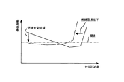
図2は、EGR装置30により供給されるEGRガスのEGR率(外部EGR率)と燃焼変動との関係を示した図である。燃焼変動が大きくなるほど、燃焼状態が悪化しているといえる。また、燃焼変動が大きくなるほど、車両サージが起こり易くなる。燃焼変動が閾値よりも小さいときには、燃焼変動が許容範囲内となり、閾値以上のときには、燃焼変動が許容範囲外となる。
FIG. 2 is a diagram showing the relationship between the EGR rate (external EGR rate) of EGR gas supplied by the
図2において、実線は、低RON燃料で且つタンブル比及び圧縮比が高い場合、破線は、高RON燃料で且つタンブル比及び圧縮比が高い場合、一点鎖線は、低RON燃料で且つタンブル比及び圧縮比が低い場合、二点鎖線は、高RON燃料で且つタンブル比及び圧縮比が低い場合を示している。なお、図2は、通路内噴射弁81及び筒内噴射弁82の両方から燃料を噴射した場合、又は通路内噴射弁81のみから燃料を噴射した場合を示している。
In FIG. 2, the solid line is a low RON fuel and the tumble ratio and the compression ratio are high, the broken line is a high RON fuel and the tumble ratio and the compression ratio are high, and the alternate long and short dash line is a low RON fuel and the tumble ratio and When the compression ratio is low, the two-dot chain line indicates a case where the fuel is high RON fuel and the tumble ratio and compression ratio are low. FIG. 2 shows a case where fuel is injected from both the in-
図2を見れば分かるように、タンブル比及び圧縮比が高い場合であって低RON燃料を用いた場合(実線)には、EGR率が低いときに燃焼変動が大きくなる。すなわち、ノッキングが発生するため、点火時期を進角させることができなくなり、車両サージが起こる。しかし、タンブル比及び圧縮比が低い場合よりも、タンブル比及び圧縮比が高い場合は、外部EGR率がより高くても燃焼変動を抑制することができる(燃焼限界が拡大する)。 As can be seen from FIG. 2, when the tumble ratio and the compression ratio are high and the low RON fuel is used (solid line), the combustion fluctuation increases when the EGR rate is low. That is, since knocking occurs, the ignition timing cannot be advanced and a vehicle surge occurs. However, when the tumble ratio and compression ratio are higher than when the tumble ratio and compression ratio are low, combustion fluctuations can be suppressed even when the external EGR rate is higher (the combustion limit is expanded).
また、図3は、タンブル比及び圧縮比が高い場合の外部EGR率と燃焼変動との関係を示した図である。実線は通路内噴射弁81及び筒内噴射弁82の両方から燃料を供給した場合を示し、一点鎖線は筒内噴射弁82のみから燃料を供給した場合を示している。実線は、通路内噴射弁81のみから燃料を供給した場合も含む。
FIG. 3 is a diagram showing the relationship between the external EGR rate and the combustion fluctuation when the tumble ratio and the compression ratio are high. The solid line indicates the case where fuel is supplied from both the in-
図3を見れば分かるように、外部EGR率が低い場合には、筒内噴射弁82のみから燃料を供給したほうが燃焼変動を抑制できる。そして、筒内噴射弁82のみから燃料を供給すれば、外部EGR率が0の場合であっても点火時期を進角させることができるので、EGRガスを供給しなくても燃焼変動を閾値よりも小さくすることができる。しかし、筒内噴射弁82のみから燃料を供給すると、より低い外部EGR率で、燃焼変動が閾値以上となる。すなわち、外部EGR率が高い場合に筒内噴射弁82のみから燃料を供給すると、燃料の霧化及び空気との混合が促進されないため、燃焼限界が低下してしまい、燃焼状態が悪化し易い。
As can be seen from FIG. 3, when the external EGR rate is low, combustion fluctuation can be suppressed by supplying fuel only from the in-
このように、EGR率によって、燃料変動を抑制し得る燃料の供給態様が異なる。 As described above, the fuel supply mode that can suppress the fuel fluctuation differs depending on the EGR rate.
そこで本実施例では、EGR装置30からEGRガスを供給していないとき、すなわちEGR弁32が全閉となっているときに、筒内噴射弁82のみから燃料を供給している。EGRガスを供給していない場合には、図3に示すように、筒内噴射弁82のみから燃料を供給したほうが、通路内噴射弁81を併用するよりも、燃焼変動を小さくすることができる。
Therefore, in this embodiment, when the EGR gas is not supplied from the
すなわち、EGRガスの供給が停止されていることにより、EGRガスによるノッキン
グ抑制効果が得られなくなるが、このときに筒内噴射弁82のみから燃料を供給することで、燃料の気化潜熱により気筒2内の温度を低下させることができるので、ノッキングの発生を抑制できる。また、ノッキングの発生を抑制できるため、点火時期を進角させることができる。これらにより、車両サージを抑制できる。なお、EGRガスの供給は、内燃機関1の温度が所定値以下のときに停止される。この所定値は、EGRガスを供給すると内燃機関1の燃焼状態が悪化し得る温度として実験等により求めておく。なお、本実施例においては内燃機関1の温度が所定値以下のときにEGRガスの供給を停止させるECU90が、本発明における停止手段に相当する。
That is, since the supply of EGR gas is stopped, the knocking suppression effect by the EGR gas cannot be obtained. At this time, by supplying the fuel only from the in-
また、EGRガスが供給されている場合には、通路内噴射弁81及び筒内噴射弁82の両方から燃料を供給する。これにより、燃料の霧化を促進させて燃焼限界を拡大することができる。
Further, when EGR gas is supplied, fuel is supplied from both the in-
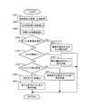
図4は、本実施例に係る燃料供給のフローを示したフローチャートである。本ルーチンは所定の時間毎にECU90により実行される。
FIG. 4 is a flowchart showing a flow of fuel supply according to the present embodiment. This routine is executed by the
ステップS101では、機関回転数及び機関負荷が取得される。すなわち、内燃機関1の運転状態が取得される。具体的には、アクセル開度センサ91およびクランクポジションセンサ92の出力値が読み込まれる。
In step S101, the engine speed and the engine load are acquired. That is, the operating state of the internal combustion engine 1 is acquired. Specifically, the output values of the
ステップS102では、内燃機関1の運転領域が、ノッキングが発生する運転領域であるか否か判定される。例えば予め規定されている中負荷以上であるか否か判定する。ステップS102で肯定判定がなされた場合にはステップS103へ進み、否定判定がなされた場合には本ルーチンを終了させる。なお、本ステップは無くても良く、その場合にはステップS101の後にステップS103を実行する。 In step S102, it is determined whether or not the operating region of the internal combustion engine 1 is an operating region where knocking occurs. For example, it is determined whether or not the load is equal to or greater than a predetermined medium load. If an affirmative determination is made in step S102, the process proceeds to step S103, and if a negative determination is made, this routine is terminated. Note that this step may be omitted, and in this case, step S103 is executed after step S101.
ステップS103では、EGR弁32の開度が0であるか否か判定される。すなわち、EGR装置30からのEGRガスの供給が停止されているか否か判定される。なお、ECU90にて算出されるEGR率が0であるか否か判定しても良い。また、EGR弁32が全閉となっても吸気管4内に残留しているEGRガスが気筒2内に供給されたり、また、EGR弁32が開かれてもEGRガスが気筒2内に導入されるまで時間がかかったりする。すなわち、EGR弁32の開度の変化に対して気筒2内に導入されるEGRガスの変化には遅れがある。この遅れを考慮して、気筒2内にEGRガスが存在していないのか否か判定しても良い。この遅れは、吸気の流速等によって変わるため、例えば内燃機関1の運転状態と関連付けて予め求めてECU90に記憶させておいても良い。そして、ステップS103で肯定判定がなされた場合にはステップS104へ進み、否定判定がなされた場合にはステップS105へ進む。
In step S103, it is determined whether or not the opening degree of the
ステップS104では、筒内噴射弁82のみから燃料を供給する。ステップS105では、通路内噴射弁81及び筒内噴射弁82の両方から燃料を供給するか、または通路内噴射弁81のみから燃料を供給する。すなわちステップS105では、少なくとも通路内噴射弁81から燃料を供給する。なお、本実施例においてはステップS104を処理するECU90が、本発明におけるEGR停止時制御手段に相当する。
In step S104, fuel is supplied only from the in-
このようにEGRガスの供給が停止されているか否かに応じて、噴射弁を使い分けることにより、燃焼変動を抑制しつつ燃費を向上させることができる。 Thus, depending on whether or not the supply of EGR gas is stopped, the fuel consumption can be improved while suppressing combustion fluctuation by properly using the injection valve.
ところで、機関回転数または機関負荷が変化している最中の過渡運転時においては、これらの変化に合わせてEGR弁32の開度も変化する。すなわち、内燃機関1の運転状態(例えば機関回転数及び機関負荷)に応じてEGR弁32の目標開度が設定される場合に
は、目標開度が絶えず変化するため、EGR弁32の目標開度(以下、目標EGR弁開度ともいう。)と実際の開度(以下、実EGR弁開度ともいう。)とに差が生じる。また、EGR弁32の開度は瞬時に変化するわけではないので、実EGR弁開度が目標EGR弁開度に合うまでに時間がかかる。EGR弁32の目標EGR弁開度と実EGR弁開度とに差が有る場合には、EGR率も目標値に到達していないため、所望の燃焼状態を得ることが困難となる。
By the way, during the transient operation while the engine speed or the engine load is changing, the opening degree of the
そこで、本実施例では、過渡運転時において、目標EGR弁開度と実EGR弁開度とに応じて全燃料噴射量に対する通路内噴射弁81からの燃料噴射量の比率(以下、吹き分け比率という。)を設定する。なお、吹き分け比率は0から1までの値であり、吹き分け比率が0のときには、筒内噴射弁82のみから燃料が供給され、吹き分け比率が1のときには、通路内噴射弁81のみから燃料が供給されるものとする。
Therefore, in the present embodiment, during the transient operation, the ratio of the fuel injection amount from the in-
吹き分け比率は、内燃機関1の運転状態に応じて設定される基準値がECU90に予め記憶されている。なお、基準値は、EGR弁32の開度に応じて決定しても良い。そして、過渡運転時においては、吹き分け比率の基準値をそのまま用いるのではなく、目標EGR弁開度に対する実EGR弁開度の比率に応じて変更した吹き分け比率を用いる。目標EGR弁開度に対する実EGR弁開度の比率は、目標EGR弁開度に対する実EGR弁開度の不足の度合いを表す値である。なお、ECU90により実際のEGR率を推定し、目標EGR率に対する実際のEGR率の比率に応じて吹き分け比率の基準値を変更しても良い。
As the blowing ratio, a reference value set in accordance with the operating state of the internal combustion engine 1 is stored in the
図5は、本実施例に係る過渡時の燃料供給のフローを示したフローチャートである。本ルーチンは所定の時間毎にECU90により実行される。なお、図4に示したフローと同じ処理がなされるステップについては、同じ符号を付して説明を省略する。
FIG. 5 is a flowchart showing a flow of fuel supply during transition according to the present embodiment. This routine is executed by the
ステップS201では、EGR弁32の目標開度(目標EGR弁開度)が取得される。目標EGR弁開度は、内燃機関1の運転状態(例えば機関回転数及び機関負荷)に応じて予め設定されており、ECU90に記憶されている。
In step S201, the target opening (target EGR valve opening) of the
ステップS202では、EGR弁32の実開度(実EGR弁開度)が取得される。すなわち、開度センサ34による測定値が読み込まれる。 In step S202, the actual opening of the EGR valve 32 (actual EGR valve opening) is acquired. That is, the measured value by the opening sensor 34 is read.
次にステップS102へ進み、肯定判定がなされた場合(ノッキングが発生する運転領域であると判定された場合)にはステップS203へ進み、否定判定がなされた場合(ノッキングが発生する領域でないと判定された場合)には吹き分け比率を変更する必要はないため、ステップS207へ進んで初期設定のままの吹き分け比率にて燃料の供給が行なわれる。初期設定の吹き分け比率は、吹き分け比率の基準値であり、内燃機関1の運転状態(例えば機関回転数及び機関負荷)に応じて設定される値である。 Next, the process proceeds to step S102, and when an affirmative determination is made (when it is determined that the operation region is knocking), the process proceeds to step S203, and when a negative determination is made (the region is not a region where knocking occurs). In this case, since it is not necessary to change the blowing ratio, the process proceeds to step S207, and the fuel is supplied at the initially set blowing ratio. The initial blowing ratio is a reference value for the blowing ratio, and is a value set according to the operating state of the internal combustion engine 1 (for example, the engine speed and the engine load).
ステップS203では、ステップS202で取得される実EGR弁開度が、ステップS201で取得される目標EGR弁開度よりも小さいか否か判定される。すなわち、EGRガスが不足しているか否か判定される。ステップS203で肯定判定がなされた場合にはステップS204へ進み、否定判定がなされた場合には吹き分け比率を変更する必要はないため、ステップS207へ進んで初期設定のままの吹き分け比率にて燃料の供給が行なわれる。 In step S203, it is determined whether or not the actual EGR valve opening acquired in step S202 is smaller than the target EGR valve opening acquired in step S201. That is, it is determined whether or not EGR gas is insufficient. If an affirmative determination is made in step S203, the process proceeds to step S204. If a negative determination is made, there is no need to change the blowing ratio, so the process proceeds to step S207 and the initial blowing ratio is maintained. Fuel is supplied.
ステップS204では、吹き分け比率を変更するために用いる吹き分け比率係数を算出する。吹き分け比率係数とは、吹き分け比率の基準値に乗じる係数であり、実EGR弁開度を目標EGR弁開度で除した値である。すなわち、目標EGR弁開度に対する実EGR
弁開度の比率を吹き分け比率係数として算出する。なお、目標となるEGR率を実際のEGR率で除した値を吹き分け比率係数としても良い。また、目標となるEGRガス量を実際のEGRガス量で除した値を吹き分け比率係数としても良い。
In step S204, a blowing ratio coefficient used for changing the blowing ratio is calculated. The blowing ratio coefficient is a coefficient that is multiplied by the reference value of the blowing ratio, and is a value obtained by dividing the actual EGR valve opening by the target EGR valve opening. That is, the actual EGR with respect to the target EGR valve opening
The ratio of the valve opening is calculated as a blowing ratio coefficient. A value obtained by dividing the target EGR rate by the actual EGR rate may be used as the blowing ratio coefficient. Further, a value obtained by dividing the target EGR gas amount by the actual EGR gas amount may be used as the blowing ratio coefficient.
ステップS205では、吹き分け比率を再設定して燃料を供給する。新たな吹き分け比率は、吹き分け比率の基準値にステップS204で算出された吹き分け比率係数を乗じて算出される。 In step S205, the blowing ratio is reset and fuel is supplied. The new blowing ratio is calculated by multiplying the reference value of the blowing ratio by the blowing ratio coefficient calculated in step S204.
ステップS206では、点火時期を再設定する。本ステップでは、ステップS204で算出される吹き分け比率係数またはステップS205で再設定される吹き分け比率に応じて点火時期を再設定する。ここで、吹き分け比率が0に近づくほど、すなわち、筒内噴射弁82により気筒2内に噴射される燃料の比率が高くなるほど、気化潜熱による温度低下が大きくなるため、点火時期を進角させることができる。一方、EGRガス量が不足することによりノッキングが発生し易くなるので、この点では点火時期を遅角させなくてはならない。これらを考慮して、点火時期を再設定する。
In step S206, the ignition timing is reset. In this step, the ignition timing is reset according to the blowing ratio coefficient calculated in step S204 or the blowing ratio reset in step S205. Here, since the temperature drop due to the latent heat of vaporization increases as the blowing ratio approaches 0, that is, as the ratio of fuel injected into the
例えば、ノッキングのし易さは実際のEGR率(実EGR弁開度としても良い。)及び吹き分け比率に応じて変化するため、実際のEGR率(または実EGR弁開度)、吹き分け比率、及び点火時期の関係を予め求めてマップ化しておいても良い。図6は、吹き分け比率と、点火進角補正値と、EGR率との関係を示した図である。横軸は吹き分け比率であり、横軸の左端は吹き分け比率が1のとき(すなわち、通路内噴射弁81のみから燃料を供給したとき)を示し、右端は吹き分け比率が0のとき(すなわち、筒内噴射弁82のみから燃料を供給したとき)を示している。また、縦軸は、点火時期進角補正値(点火時期の進角量の補正値)であり、数値が大きいほど(図6の上側ほど)進角量が大きくなる。点火時期進角補正値は、内燃機関1の運転状態に応じて決定される点火時期に対しての進角量である。図6に示すように、吹き分け比率が0に近づくほど、すなわち、筒内噴射弁82により気筒2内に噴射される燃料の比率が高くなるほど、点火時期の進角量を大きくしている(点火進角補正値を大きくしている)。また、EGR率が高くなるほど、点火時期の進角量を大きくしている(点火進角補正値を大きくしている)。このマップに新たな吹き分け比率及び実際のEGR率(または実EGR弁開度)を代入することにより、新たな点火時期を得ることができる。
For example, since the ease of knocking varies depending on the actual EGR rate (may be the actual EGR valve opening) and the blowing ratio, the actual EGR rate (or actual EGR valve opening), the blowing ratio , And the relationship between the ignition timings may be obtained and mapped in advance. FIG. 6 is a diagram showing the relationship among the blowing ratio, the ignition advance correction value, and the EGR rate. The horizontal axis is the blowing ratio, the left end of the horizontal axis indicates when the blowing ratio is 1 (that is, when fuel is supplied only from the
また、吹き分け比率が基準値のときの点火時期と、筒内噴射弁82のみから燃料を供給したときの点火時期と、の差に吹き分け比率係数を乗じた値を、筒内噴射弁82のみから燃料を供給したときの点火時期に加えることによっても、新たな吹き分け比率に応じた点火時期を算出することができる。
Further, a value obtained by multiplying the difference between the ignition timing when the blowing ratio is the reference value and the ignition timing when the fuel is supplied only from the in-
このように、目標EGR弁開度に対する実EGR弁開度の比率に応じて吹き分け比率を設定することにより、燃焼状態に応じた設定が可能となる。なお、本実施例においてはステップS203から206を処理するECU90が、本発明における過渡時制御手段に相当する。
Thus, setting according to the combustion state is possible by setting the blowing ratio according to the ratio of the actual EGR valve opening to the target EGR valve opening. In this embodiment, the
以上説明したように本実施例によれば、EGR弁32の開度またはEGR率に応じてノッキングの発生のし易さを把握し、これに対し気筒2内への燃料供給量と吸気ポート3内への燃料供給量との比率を変化させることで、ノッキングの発生を抑制できる。また、このようにノッキングの発生を抑制すると点火時期を進角させることができるため、車両サージを抑制できる。
As described above, according to the present embodiment, the ease of occurrence of knocking is grasped according to the opening degree of the
本実施例では、実施例1とは異なり、機関回転数または機関負荷が変化している最中の
過渡運転時において、目標EGR弁開度が全開または全開近傍の場合には、EGR弁開度が例えば70%のときの吹き分け比率を基準として、吹き分け比率を再設定する。
In the present embodiment, unlike in the first embodiment, when the target EGR valve opening is fully open or in the vicinity of the fully open during transient operation while the engine speed or the engine load is changing, the EGR valve opening is For example, the blowing ratio is reset with reference to the blowing ratio when 70%.
ここで、図7は、EGR弁32の開度とEGR通路31におけるEGRガスの流量との関係を示した図である。また、図8は、EGR弁32の開度と目標吹き分け比率との関係を示した図である。図7及び図8において、Aは目標開度(全開であり開度100%)、Bは例えば全開に対して70%となる開度である。
Here, FIG. 7 is a diagram showing the relationship between the opening degree of the
図7を見れば分かるように、EGR弁32の開度が大きくなるほど、EGRガスの流量は増加するが、EGRガスの流量の増加度合いは次第に小さくなる。例えば、EGR弁32が全開近くで開度が30%異なる場合と、全閉近くで開度が30%異なる場合とでは、全開近くのほうがEGRガスの流量の変化が少ない。
As can be seen from FIG. 7, as the opening degree of the
すなわち、目標EGR弁開度が全開近傍の場合には、実EGR弁開度が目標EGR弁開度となっていなくても、EGRガスの流量は目標EGR弁開度のときと殆ど変わらないこともある。そこで、EGR弁32の開度の変化に対してEGRガスの流量の変化が小さい領域では、実施例1とは異なり、ある程度の開度(例えば70%)を基準として吹き分け比率を再設定する。そして、この基準となる開度よりも大きな開度のときには、基準となる開度のときに設定された吹き分け比率を用いる。
That is, when the target EGR valve opening is in the vicinity of full open, the flow rate of EGR gas should be almost the same as that at the target EGR valve opening even if the actual EGR valve opening is not the target EGR valve opening. There is also. Therefore, in the region where the change in the flow rate of the EGR gas is small relative to the change in the opening degree of the
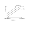
ここで、図8において、実線は本実施例により設定される吹き分け比率を示し、一点鎖線は実施例1により設定される吹き分け比率を示している。このように、本実施例により設定される吹き分け比率は、実施例1で設定される吹き分け比率よりも全体的に高くなる。本実施例では、EGRガスの実際の流量に即した吹き分け比率を設定している。 Here, in FIG. 8, the solid line indicates the blowing ratio set by the present embodiment, and the alternate long and short dash line indicates the blowing ratio set by the first embodiment. Thus, the blowing ratio set by the present embodiment is generally higher than the blowing ratio set by the first embodiment. In this embodiment, the blowing ratio is set in accordance with the actual flow rate of the EGR gas.
図9は、本実施例に係る燃料供給のフローを示したフローチャートである。本ルーチンは所定の時間毎にECU90により実行される。なお、前記フローと同じ処理がなされるステップについては、同じ符号を付して説明を省略する。
FIG. 9 is a flowchart showing a flow of fuel supply according to the present embodiment. This routine is executed by the
ステップS102で肯定判定がなされた場合、すなわち、内燃機関1の運転領域が、ノッキングが発生する運転領域であると判定された場合には、ステップS301へ進む。 If an affirmative determination is made in step S102, that is, if it is determined that the operating region of the internal combustion engine 1 is an operating region where knocking occurs, the process proceeds to step S301.
ステップS301では、目標EGR弁開度が全開領域であるか否か判定される。全開領域は、全開のみとしても良く、全開と同じに扱っても良い領域を含んでいても良い。本ステップでは、EGR弁32の開度が変化してもEGRガスの流量が殆ど変化しない領域に目標EGR弁開度が設定されているか否か判定している。ステップS301で肯定判定がなされた場合にはステップS302へ進む。一方、否定判定がなされた場合にはステップS203へ進み、それ以降は実施例1と同じ処理がなされる。
In step S301, it is determined whether or not the target EGR valve opening is in a fully open region. The fully open area may be only fully open or may include an area that may be handled in the same manner as the fully open area. In this step, it is determined whether or not the target EGR valve opening is set in a region where the flow rate of the EGR gas hardly changes even when the opening of the
ステップS302では、仮目標EGR弁開度が取得される。仮目標EGR弁開度は、吹き分け比率を算出するために設定されるEGR弁32の開度であり図7,8のBの開度に相当する。この仮目標EGR弁開度は、最終的な目標EGR弁開度のときと比較してEGRガス流量の差が小さい開度であり、例えば全開の70%の開度である。なお、EGRガスの流量は、最終的な目標EGR弁開度、機関負荷(吸気管4内の負圧)によって変化するため、仮目標EGR弁開度、最終的な目標EGR弁開度、及び機関負荷の関係をマップ化しておき、該マップから仮目標EGR弁開度を得ても良い。また、現時点での負圧、及びEGR弁32の開度とEGRガスの流量との関係から仮目標EGR弁開度を得ても良い。
In step S302, the temporary target EGR valve opening is acquired. The temporary target EGR valve opening is an opening of the
ステップS303では、ステップS202で取得される実EGR弁開度が、ステップS
302で取得される仮目標EGR弁開度よりも小さいか否か判定される。すなわち、EGRガスが不足しているか否か判定される。ステップS303で肯定判定がなされた場合にはステップS304へ進み、否定判定がなされた場合には吹き分け比率を変更する必要はないため、ステップS207へ進んで初期設定のままの吹き分け比率にて燃料の供給が行なわれる。
In step S303, the actual EGR valve opening acquired in step S202 is determined as step S202.
It is determined whether or not the temporary target EGR valve opening obtained in 302 is smaller. That is, it is determined whether or not EGR gas is insufficient. If an affirmative determination is made in step S303, the process proceeds to step S304. If a negative determination is made, there is no need to change the blowing ratio, so the process proceeds to step S207 and the initial blowing ratio is maintained. Fuel is supplied.
ステップS304では、吹き分け比率係数を算出する。吹き分け比率係数は、実EGR弁開度を仮目標EGR弁開度で除した値である。すなわち、仮目標EGR弁開度に対する実EGR弁開度の比率を吹き分け比率係数として算出する。その後、ステップS205へ進む。 In step S304, a blowing ratio coefficient is calculated. The blowing ratio coefficient is a value obtained by dividing the actual EGR valve opening by the temporary target EGR valve opening. That is, the ratio of the actual EGR valve opening to the temporary target EGR valve opening is calculated as the blowing ratio coefficient. Thereafter, the process proceeds to step S205.
このように、EGR弁32の開度が最終的な目標EGR弁開度である全開ではなく、EGRガスの流量の差が小さいある程度の開度を基準とすることにより、EGR流量が殆ど変化することのないEGR弁32の開度のときに吹き分け比率を変化させる必要がなくなるため、制御を簡略化することができる。
As described above, the EGR flow rate is almost changed by setting the opening degree of the
本実施例では、実施例1とは異なり、EGRガスの導入が開始される温度域において、EGR弁32の開度を内燃機関1の温度に応じて除変させつつ、EGR弁32の開度に基づいて吹き分け比率を決定する。
In the present embodiment, unlike the first embodiment, the opening degree of the
ここで、導入できるEGRガス量には内燃機関1の温度による制約があり、機関温度が低いときには燃焼状態の悪化を抑制するためにEGRガスの供給が停止される。EGRガスの供給が開始される温度域では、ノッキングの発生を抑制するために必要なEGRガス量に対して、それよりも少ない量しかEGRガスを供給することができない。そして、内燃機関1の温度上昇と共にEGRガスの供給量を増加するため、EGRガス量の増加は緩慢である。そうすると、EGRガス量が十分となるまでは、ノッキングが発生する虞がある。これに対し本実施例では、このような温度域において、吹き分け比率をEGR弁32の開度に基づいて設定している。
Here, the amount of EGR gas that can be introduced is limited by the temperature of the internal combustion engine 1, and when the engine temperature is low, the supply of EGR gas is stopped to suppress the deterioration of the combustion state. In the temperature range where the supply of EGR gas is started, the EGR gas can be supplied only in an amount smaller than the amount of EGR gas necessary for suppressing the occurrence of knocking. And since the supply amount of EGR gas increases with the temperature rise of the internal combustion engine 1, the increase in the EGR gas amount is slow. As a result, knocking may occur until the amount of EGR gas becomes sufficient. On the other hand, in this embodiment, the blowing ratio is set based on the opening degree of the
図10は、本実施例に係る燃料供給のフローを示したフローチャートである。本ルーチンは所定の時間毎にECU90により実行される。なお、前記フローと同じ処理がなされるステップについては、同じ符号を付して説明を省略する。
FIG. 10 is a flowchart showing a flow of fuel supply according to the present embodiment. This routine is executed by the
ステップS401では、機関回転数及び機関負荷、さらには内燃機関1の冷却水温度が取得される。内燃機関1の冷却水温度は温度センサ94により得る。
In step S401, the engine speed, the engine load, and the coolant temperature of the internal combustion engine 1 are acquired. The coolant temperature of the internal combustion engine 1 is obtained by the
ステップS402では、EGR弁開度補正係数が算出される。EGR弁開度補正係数とは、目標EGR弁開度に対して乗じることで新たな目標EGR弁開度を得るための係数であり、EGR弁32の開度を冷却水温度に応じて補正するための係数である。冷却水温度が閾値よりも低い場合には、EGR弁32の開度は0となるが、冷却水温度が閾値となるとEGR弁32が開き始める。そして、冷却水温度が高くなるほど、実EGR弁開度を目標EGR弁開度に近づけるようにEGR弁開度補正係数が設定される。冷却水温度の閾値や、EGR弁開度補正係数は、内燃機関1の種類等により変わるため、予め最適値を実験等により求めてマップ化しておく。
In step S402, an EGR valve opening correction coefficient is calculated. The EGR valve opening correction coefficient is a coefficient for obtaining a new target EGR valve opening by multiplying the target EGR valve opening, and corrects the opening of the
ステップS403では、目標EGR弁開度が算出される。目標EGR弁開度は、例えば機関回転数及び機関負荷により設定される目標EGR弁開度にEGR弁開度補正係数を乗じて新たな目標EGR弁開度として算出される。内燃機関1の冷却水温度が閾値よりも低い場合には、目標EGR弁開度は0となる。なお、本実施例では、目標EGR弁開度と実
EGR弁開度は等しいものとする。
In step S403, the target EGR valve opening is calculated. The target EGR valve opening is calculated as a new target EGR valve opening by, for example, multiplying the target EGR valve opening set by the engine speed and the engine load by the EGR valve opening correction coefficient. When the coolant temperature of the internal combustion engine 1 is lower than the threshold value, the target EGR valve opening is zero. In the present embodiment, the target EGR valve opening and the actual EGR valve opening are assumed to be equal.
ステップS103では、EGR弁32の開度が0であるか否か判定され、肯定判定がなされた場合にはステップS104へ進んで筒内噴射弁82のみから燃料が供給される。ステップS103で否定判定がなされた場合、すなわち、EGR弁32が開かれている場合にはステップS102へ進む。
In step S103, it is determined whether or not the opening degree of the
ステップS102では、内燃機関1の運転領域が、ノッキングが発生する運転領域であるか否か判定される。ステップS102で肯定判定がなされた場合にはステップS404へ進み、否定判定がなされた場合にはステップS207へ進んで、初期設定のままの吹き分け比率にて燃料の供給が行なわれる。 In step S102, it is determined whether or not the operating region of the internal combustion engine 1 is an operating region where knocking occurs. If an affirmative determination is made in step S102, the process proceeds to step S404, and if a negative determination is made, the process proceeds to step S207, and fuel is supplied at the initial blowing ratio.
ステップS404では、吹き分け比率が算出される。吹き分け比率は、吹き分け比率の基準値にEGR弁開度補正係数を乗じることにより得る。すなわち、目標EGR弁開度が小さくされている分、ノッキングが発生し易いため、筒内噴射弁82からの燃料供給量の比率を高くする。このように、EGR弁32の開度に応じて吹き分け比率を設定している。なお、EGR弁32の開度は、冷却水温度に応じて決定されているため、冷却水温度に応じて吹き分け比率を設定しても良い。その後ステップS405へ進んで、ステップS404で算出される吹き分け比率にて燃料が供給される。
In step S404, the blowing ratio is calculated. The blowing ratio is obtained by multiplying the reference value of the blowing ratio by the EGR valve opening correction coefficient. That is, since the target EGR valve opening is reduced, knocking is likely to occur, so the ratio of the fuel supply amount from the in-
なお、本実施例においては、ステップS402,403,404,405を処理するECU90が、本発明におけるEGR供給開始時制御手段に相当する。
In this embodiment, the
このように、冷却水温度に応じて設定されるEGR弁32の開度に応じて吹き分け比率を設定することにより、そのときのEGRガス量に応じた吹き分け比率を設定することが可能となるため、ノッキングの発生を抑制できる。
Thus, by setting the blowing ratio according to the opening degree of the
本実施例では、冷間時に筒内噴射弁82からの燃料噴射量が多いためにオイルの希釈が顕著となる温度域(例えば、常温以下)において、筒内噴射弁82からの燃料の供給を停止させ、通路内噴射弁81のみから燃料を供給する。内燃機関1の温度がこの温度域よりも高い場合には、EGRガスが供給されていない場合にのみ、筒内噴射弁82のみから燃料を供給する。
In the present embodiment, the fuel is supplied from the in-
図11は、内燃機関1の冷却水温度と吹き分け比率との関係を示した図である。常温以下の場合には、吹き分け比率を1とし、通路内噴射弁81のみから燃料を供給する。常温よりも高い場合であって、EGRガスが供給されていないとき(EGR弁32の開度が0のとき)には、吹き分け比率を0とし、筒内噴射弁82のみから燃料を供給する。常温よりも高い場合であって、EGRガスが供給されているとき(EGR弁32が開かれているとき)には、上記実施例に従って吹き分け比率を設定する。
FIG. 11 is a diagram showing the relationship between the cooling water temperature and the blowing ratio of the internal combustion engine 1. When the temperature is below normal temperature, the blowing ratio is set to 1, and the fuel is supplied only from the
図12は、本実施例に係る燃料供給のフローを示したフローチャートである。本ルーチンは所定の時間毎にECU90により実行される。なお、前記フローと同じ処理がなされるステップについては、同じ符号を付して説明を省略する。
FIG. 12 is a flowchart showing a flow of fuel supply according to the present embodiment. This routine is executed by the
ステップS501では、内燃機関1の温度が、オイル希釈が発生する温度であるか否か判定される。ここでは、内燃機関1の温度が、オイル希釈が許容範囲を超える温度であるか否か判定しても良い。また、PM・PNが発生する温度であるか否か判定しても良い。これらの温度は、例えば常温(例えば15℃から20℃)としても良く、予め実験等により求めておいても良い。 In step S501, it is determined whether or not the temperature of the internal combustion engine 1 is a temperature at which oil dilution occurs. Here, it may be determined whether or not the temperature of the internal combustion engine 1 is a temperature at which oil dilution exceeds an allowable range. Further, it may be determined whether or not the temperature is such that PM · PN is generated. These temperatures may be, for example, normal temperature (for example, 15 ° C. to 20 ° C.), or may be obtained in advance through experiments or the like.
ステップS501で肯定判定がなされた場合には、ステップS502へ進んで、通路内噴射弁81のみから燃料を供給する。ステップS502で否定判定がなされた場合にはステップS103へ進み、以降は実施例3と同じ処理がなされる。
If an affirmative determination is made in step S501, the process proceeds to step S502, where fuel is supplied only from the in-
このようにして、内燃機関1の温度が常温よりも低い場合には、通路内噴射弁81のみから燃料を供給することにより、オイルが燃料で希釈されることを抑制したり、PM・PNの発生を抑制したりすることができる。
In this way, when the temperature of the internal combustion engine 1 is lower than the normal temperature, by supplying the fuel only from the in-
1 内燃機関
2 気筒
3 吸気ポート
4 吸気管
5 吸気弁
6 吸気側カム
7 排気ポート
8 排気管
9 排気弁
10 シリンダヘッド
11 排気側カム
13 クランクシャフト
14 コンロッド
15 ピストン
16 吸気絞り弁
30 EGR装置
31 EGR通路
32 EGR弁
33 EGRクーラ
34 開度センサ
81 通路内噴射弁
82 筒内噴射弁
83 点火プラグ
90 ECU
91 アクセル開度センサ
92 クランクポジションセンサ
93 エアフローメータ
94 温度センサ
DESCRIPTION OF SYMBOLS 1
91
Claims (5)
前記内燃機関の気筒内に燃料を噴射する筒内噴射弁と、
前記内燃機関の排気通路と吸気通路とを接続し排気の一部をEGRガスとして吸気通路へ供給するEGR装置と、
EGRガス量が目標量に対して不足する過渡運転時においては、定常運転時よりも全燃料噴射量に対する前記筒内噴射弁からの燃料噴射量の比率を高め、且つ、高めた後の全燃料噴射量に対する前記筒内噴射弁からの燃料噴射量の比率及びEGR率に基づいて点火時期を設定する過渡時制御手段と、
を備えることを特徴とする内燃機関の制御装置。 An in-passage injection valve for injecting fuel into the intake passage of the internal combustion engine;
An in-cylinder injection valve for injecting fuel into the cylinder of the internal combustion engine;
An EGR device that connects an exhaust passage and an intake passage of the internal combustion engine and supplies a part of the exhaust gas as EGR gas to the intake passage;
At the time of transient operation where the EGR gas amount is insufficient with respect to the target amount, the ratio of the fuel injection amount from the in-cylinder injection valve to the total fuel injection amount is increased compared to that during steady operation, and the total fuel after the increase Transient control means for setting the ignition timing based on the ratio of the fuel injection amount from the in-cylinder injection valve to the injection amount and the EGR rate;
A control device for an internal combustion engine, comprising:
前記内燃機関の気筒内に燃料を噴射する筒内噴射弁と、
前記内燃機関の排気通路と吸気通路とを接続し排気の一部をEGRガスとして吸気通路へ供給するEGR装置と、
前記内燃機関の温度を検知する検知手段と、
前記検知手段により検知される内燃機関の温度が所定値以下のときに、前記EGR装置によるEGRガスの供給を停止させる停止手段と、
前記停止手段によりEGRガスの供給が停止されている間は、前記通路内噴射弁からの燃料の噴射を停止させて前記筒内噴射弁のみから燃料を噴射させるEGR停止時制御手段と、
を備えることを特徴とする内燃機関の制御装置。 An in-passage injection valve for injecting fuel into the intake passage of the internal combustion engine;
An in-cylinder injection valve for injecting fuel into the cylinder of the internal combustion engine;
An EGR device that connects an exhaust passage and an intake passage of the internal combustion engine and supplies a part of the exhaust gas as EGR gas to the intake passage;
Detecting means for detecting the temperature of the internal combustion engine;
Stop means for stopping supply of EGR gas by the EGR device when the temperature of the internal combustion engine detected by the detection means is equal to or lower than a predetermined value;
EGR stop time control means for stopping fuel injection from the in-passage injection valve and injecting fuel only from the in-cylinder injection valve while the supply of EGR gas is stopped by the stop means;
A control device for an internal combustion engine, comprising:
前記内燃機関の温度が前記所定値以下から上昇して該所定値よりも高くなったときに、前記EGR弁の開度と、全燃料噴射量に対する前記通路内噴射弁からの燃料噴射量の比率と、を前記検知手段により検知される温度に応じて設定するEGR供給開始時制御手段を備えることを特徴とする請求項2に記載の内燃機関の制御装置。 The EGR device includes an EGR passage that connects an exhaust passage and an intake passage of the internal combustion engine, and an EGR valve that adjusts a flow area of the EGR gas by adjusting a passage area of the EGR passage,
When the temperature of the internal combustion engine rises below the predetermined value and becomes higher than the predetermined value, the ratio of the opening of the EGR valve and the fuel injection amount from the in-passage injection valve to the total fuel injection amount The control device for an internal combustion engine according to claim 2, further comprising: an EGR supply start time control unit that sets the value according to the temperature detected by the detection unit.
Priority Applications (1)
| Application Number | Priority Date | Filing Date | Title |
|---|---|---|---|
| JP2010001926A JP2011140902A (en) | 2010-01-07 | 2010-01-07 | Control device of internal combustion engine |
Applications Claiming Priority (1)
| Application Number | Priority Date | Filing Date | Title |
|---|---|---|---|
| JP2010001926A JP2011140902A (en) | 2010-01-07 | 2010-01-07 | Control device of internal combustion engine |
Publications (1)
| Publication Number | Publication Date |
|---|---|
| JP2011140902A true JP2011140902A (en) | 2011-07-21 |
Family
ID=44456925
Family Applications (1)
| Application Number | Title | Priority Date | Filing Date |
|---|---|---|---|
| JP2010001926A Withdrawn JP2011140902A (en) | 2010-01-07 | 2010-01-07 | Control device of internal combustion engine |
Country Status (1)
| Country | Link |
|---|---|
| JP (1) | JP2011140902A (en) |
Cited By (5)
| Publication number | Priority date | Publication date | Assignee | Title |
|---|---|---|---|---|
| JP2014080916A (en) * | 2012-10-16 | 2014-05-08 | Toyota Motor Corp | Control device of internal combustion engine |
| JP2014240627A (en) * | 2013-06-12 | 2014-12-25 | 日産自動車株式会社 | Control device of internal combustion engine and control method |
| CN105275633A (en) * | 2014-05-28 | 2016-01-27 | 福特环球技术公司 | Method and system for pre-ignition control |
| CN106593665A (en) * | 2016-12-13 | 2017-04-26 | 上海汽车集团股份有限公司 | Low-emission and high-power-performance starting control method of diesel engine vehicle |
| CN106662031A (en) * | 2014-08-01 | 2017-05-10 | 丰田自动车株式会社 | Control system for an internal combustion engine |
-
2010
- 2010-01-07 JP JP2010001926A patent/JP2011140902A/en not_active Withdrawn
Cited By (8)
| Publication number | Priority date | Publication date | Assignee | Title |
|---|---|---|---|---|
| JP2014080916A (en) * | 2012-10-16 | 2014-05-08 | Toyota Motor Corp | Control device of internal combustion engine |
| CN104520562A (en) * | 2012-10-16 | 2015-04-15 | 丰田自动车株式会社 | Control device and control method for internal combustion engine |
| US9670866B2 (en) | 2012-10-16 | 2017-06-06 | Toyota Jidosha Kabushiki Kaisha | Control device and control method for internal combustion engine |
| JP2014240627A (en) * | 2013-06-12 | 2014-12-25 | 日産自動車株式会社 | Control device of internal combustion engine and control method |
| CN105275633A (en) * | 2014-05-28 | 2016-01-27 | 福特环球技术公司 | Method and system for pre-ignition control |
| CN105275633B (en) * | 2014-05-28 | 2020-04-14 | 福特环球技术公司 | Method and system for pre-ignition control |
| CN106662031A (en) * | 2014-08-01 | 2017-05-10 | 丰田自动车株式会社 | Control system for an internal combustion engine |
| CN106593665A (en) * | 2016-12-13 | 2017-04-26 | 上海汽车集团股份有限公司 | Low-emission and high-power-performance starting control method of diesel engine vehicle |
Similar Documents
| Publication | Publication Date | Title |
|---|---|---|
| JP5962534B2 (en) | Intercooler temperature controller | |
| US8078387B2 (en) | Control apparatus for spark-ignition engine | |
| JP5939263B2 (en) | Control device for internal combustion engine | |
| US8141533B2 (en) | Control apparatus and method for internal combustion engine | |
| US20090299610A1 (en) | Control apparatus of spark ignition internal combustion engine | |
| JP2011140902A (en) | Control device of internal combustion engine | |
| CN106030084B (en) | Control device and control method for internal combustion engine | |
| JP5482010B2 (en) | Control device for internal combustion engine | |
| JP4529835B2 (en) | Control device for internal combustion engine | |
| JP5045658B2 (en) | Control device for internal combustion engine | |
| JP6225969B2 (en) | Control device and control method for internal combustion engine with supercharger | |
| JP2019027417A (en) | Control device of internal combustion engine | |
| WO2010095258A1 (en) | Internal combustion engine | |
| JP2012087641A (en) | Fuel injection device | |
| JP2010168931A (en) | Ignition timing control device for spark ignition type internal combustion engine | |
| JP2009216035A (en) | Control device of internal combustion engine | |
| JP5035285B2 (en) | Control device for an internal combustion engine with a supercharger | |
| JP2009114931A (en) | Control device for internal combustion engine | |
| JP2009191752A (en) | Exhaust gas recirculation device for internal combustion engine | |
| JP6527393B2 (en) | Control device for internal combustion engine | |
| JP4124134B2 (en) | Fuel injection control method for internal combustion engine | |
| JP2012193710A (en) | Fuel injection control device of internal combustion engine | |
| JP2010127087A (en) | Combustion control device of internal combustion engine | |
| JP2007032298A (en) | Spark ignition type internal combustion engine | |
| JP2008106612A (en) | Glow plug control device for diesel engine |
Legal Events
| Date | Code | Title | Description |
|---|---|---|---|
| A300 | Application deemed to be withdrawn because no request for examination was validly filed |
Free format text: JAPANESE INTERMEDIATE CODE: A300 Effective date: 20130402 |